
Fire Resistance of Unprotected Ultra Shallow Floor Beams ...
19
Fire Resistance of Unprotected Ultra Shallow Floor Beams (USFB): A Numerical Investigation C. Maraveas*, School of Mechanical, Aerospace and Civil Engineering, University of Manchester, Manchester, UK K. D. Tsavdaridis, School of Civil Engineering, University of Leeds, Leeds, UK A. Nadjai, School of Build Environment, Ulster University, Londonderry, UK Received: 14 December 2014/Accepted: 7 November 2015 Abstract. This paper presents the fire resistance behaviour of partially encased in concrete ultra shallow floor beams (USFB) using numerical analysis method based on material specifications of the EN1994-1-2. Investigating the behaviour of USFBs under elevated temperatures is crucial in determining their fire resistance and evaluat- ing their overall performance in contemporary construction. Even though the manu- facturing company provides fire resistances for USFBs based on EC4-1-2 procedures, their response to elevated temperature effects remains up to date neither well docu- mented nor clearly understood. The analyses involved two different beams of span 5 m and 8 m respectively, as specified by the manufacturer. Analysis results showed that such beams, when unprotected, experience severe temperature gradients if exposed to fire, as the lower flange still remains unprotected in contrast to the con- crete encased part of the cross-section. As it was anticipated, the moment capacity governs the fire resistance of the beams and the load factor highly effects the elevated temperature behaviour. In addition, the loss of the lower flange, which develops high temperatures, is not compensated by the web and consequently the moment capacity ultimately depends on the temperature of the lower flange. Results also suggest that simulated beams sustained the applied load for approximately 40 min of exposure to the standard fire. Keywords: Ultra shallow floor beams, Fire resistance, Composite, Flooring systems, Moment capacity, Shear capacity 1. Introduction Various shallow floor systems have been developed recently. The most commonly encountered in the industry are the ‘‘slim floor’’ and the ‘‘slim deck’’ systems. Sev- eral companies have developed their own systems, such as the ultra shallow floor beam (USFB) composite deck system [1]. The behaviour of such flooring systems when exposed to fire is generally satisfactory, because the encasing (plug) concrete acts as thermal insulation, even though the lower flange is unprotected. The * Correspondence should be addressed to: C. Maraveas, E-mail: [email protected] Fire Technology, 53, 609–627, 2017 Ó 2016 The Author(s). This article is published with open access at Springerlink.com. Manufactured in The United States DOI: 10.1007/s10694-016-0583-5 1
Transcript of Fire Resistance of Unprotected Ultra Shallow Floor Beams ...

Fire Resistance of Unprotected UltraShallow Floor Beams (USFB): A NumericalInvestigation
C. Maraveas*, School of Mechanical, Aerospace and Civil Engineering,University of Manchester, Manchester, UK
K. D. Tsavdaridis, School of Civil Engineering, University of Leeds, Leeds, UK
A. Nadjai, School of Build Environment, Ulster University, Londonderry, UK
Received: 14 December 2014/Accepted: 7 November 2015
Abstract. This paper presents the fire resistance behaviour of partially encased inconcrete ultra shallow floor beams (USFB) using numerical analysis method based on
material specifications of the EN1994-1-2. Investigating the behaviour of USFBsunder elevated temperatures is crucial in determining their fire resistance and evaluat-ing their overall performance in contemporary construction. Even though the manu-facturing company provides fire resistances for USFBs based on EC4-1-2 procedures,
their response to elevated temperature effects remains up to date neither well docu-mented nor clearly understood. The analyses involved two different beams of span5 m and 8 m respectively, as specified by the manufacturer. Analysis results showed
that such beams, when unprotected, experience severe temperature gradients ifexposed to fire, as the lower flange still remains unprotected in contrast to the con-crete encased part of the cross-section. As it was anticipated, the moment capacity
governs the fire resistance of the beams and the load factor highly effects the elevatedtemperature behaviour. In addition, the loss of the lower flange, which develops hightemperatures, is not compensated by the web and consequently the moment capacityultimately depends on the temperature of the lower flange. Results also suggest that
simulated beams sustained the applied load for approximately 40 min of exposure tothe standard fire.
Keywords: Ultra shallow floor beams, Fire resistance, Composite, Flooring systems, Moment capacity,
Shear capacity
1. Introduction
Various shallow floor systems have been developed recently. The most commonlyencountered in the industry are the ‘‘slim floor’’ and the ‘‘slim deck’’ systems. Sev-eral companies have developed their own systems, such as the ultra shallow floorbeam (USFB) composite deck system [1]. The behaviour of such flooring systemswhen exposed to fire is generally satisfactory, because the encasing (plug) concreteacts as thermal insulation, even though the lower flange is unprotected. The
* Correspondence should be addressed to: C. Maraveas, E-mail: [email protected]
Fire Technology, 53, 609–627, 2017
� 2016 The Author(s). This article is published with open access at Springerlink.com.
Manufactured in The United States
DOI: 10.1007/s10694-016-0583-5
1

results of relevant parametric analyses [2–4] have shown that the fire resistance ofsuch shallow systems is governed by deflection, as they experience bowing result-ing from considerable thermal gradients.
In spite of the fact that the fire behaviour of slim floor and slim deck systemshas been investigated by various researchers [2, 5–10], systems proposed by othermanufacturing companies, such as the USFBs [1], have not been sufficiently stud-ied at elevated temperatures. The USFBs seem to exhibit significantly differentbehaviour than the aforementioned systems (which generally have a satisfactoryfire resistance) as they use shallow sections which are protected less by the con-crete [2] while the web, which has to develop stresses after the capacity loss of thelower flange, in order to develop a moment capacity, is perforated. The manufac-turing company though certifies (based on EC4-1-2 [12] procedures) for each beamthe appropriate fire insulation. Due to the absence of vital information for evalu-ating the Eurocodes procedures for the specific system and the fact that experi-mental results are not available, the authors conducted a numerical simulation ofsuch USFB systems exposed to fire. For this purpose, finite element (FE) analyseswith the commercial program ABAQUS were carried out. The methodology usedin the current USFB analysis is similar to the model used in the analysis of asym-metric slim floor beams in fire presented by Maraveas et al. [2].
Two commonly used simply supported isolated USFBs have been analysed. Theconsidered span lengths are 5 m and 8 m, with shape and arrangement as descri-bed in Section 2. Additional checks were made to determine the performance ofthe section in fire and ensure that the serviceability limit state stresses were notexcessive as evaluated by the manufacturer’s software [1]. Table 1 synopsises thenormal temperature maximum design unity factors and the critical load combina-tion for the two considered beams. The calculations performed with the use of thesoftware Cellbeam v9.0 (certified by the Steel Construction Institute). The boldvalues in Table 1 refer to the critical code checks/verifications according to amodified EC4 design procedure proposed by the SCI and used internally by ASDWestok (RT1371).
Table 1Normal Temperature Maximum Design Unity Factors for the CriticalLoad Combination
Failure mode Beam A Beam B
Vertical shear 0.51 0.41
Horizontal shear 0.98 0.76
Moment shear interaction 1.00 0.91
Vierendeel bending 1.00 0.91
Longitudinal shear in slab 0.16 0.14
Vibration (Hz) 5.49 3.27
Imposed deflection (mm) 8.18 19.03
610 Fire Technology 2017
2. USFB System
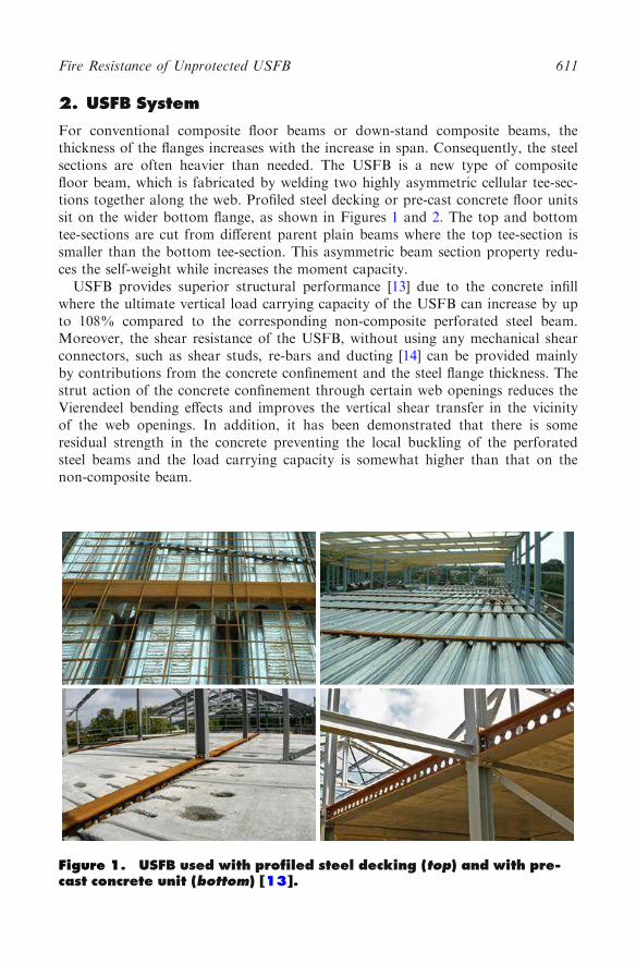
For conventional composite floor beams or down-stand composite beams, thethickness of the flanges increases with the increase in span. Consequently, the steelsections are often heavier than needed. The USFB is a new type of compositefloor beam, which is fabricated by welding two highly asymmetric cellular tee-sec-tions together along the web. Profiled steel decking or pre-cast concrete floor unitssit on the wider bottom flange, as shown in Figures 1 and 2. The top and bottomtee-sections are cut from different parent plain beams where the top tee-section issmaller than the bottom tee-section. This asymmetric beam section property redu-ces the self-weight while increases the moment capacity.
USFB provides superior structural performance [13] due to the concrete infillwhere the ultimate vertical load carrying capacity of the USFB can increase by upto 108% compared to the corresponding non-composite perforated steel beam.Moreover, the shear resistance of the USFB, without using any mechanical shearconnectors, such as shear studs, re-bars and ducting [14] can be provided mainlyby contributions from the concrete confinement and the steel flange thickness. Thestrut action of the concrete confinement through certain web openings reduces theVierendeel bending effects and improves the vertical shear transfer in the vicinityof the web openings. In addition, it has been demonstrated that there is someresidual strength in the concrete preventing the local buckling of the perforatedsteel beams and the load carrying capacity is somewhat higher than that on thenon-composite beam.
Figure 1. USFB used with profiled steel decking (top) and with pre-cast concrete unit (bottom) [13].
Fire Resistance of Unprotected USFB 611
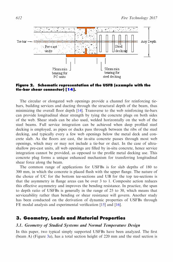
The circular or elongated web openings provide a channel for reinforcing tie-bars, building services and ducting through the structural depth of the beam, thusminimizing the overall floor depth [14]. Transverse to the web reinforcing tie-barscan provide longitudinal shear strength by tying the concrete plugs on both sidesof the web. Shear studs can be also used, welded horizontally on the web of thesteel beams. Full service integration can be achieved when deep profiled steeldecking is employed, as pipes or ducks pass through between the ribs of the steeldecking, and typically every a few web openings below the metal deck and con-crete slab. As the floors are cast, the in-situ concrete passes through most webopenings, which may or may not include a tie-bar or duct. In the case of ultra-shallow pre-cast units, all web openings are filled by in-situ concrete, hence serviceintegration cannot be provided, as opposed to the profile metal decking use. Thisconcrete plug forms a unique enhanced mechanism for transferring longitudinalshear force along the beam.
The common range of applications for USFBs is for slab depths of 180 to300 mm, in which the concrete is placed flush with the upper flange. The nature ofthe choice of UC for the bottom tee-sections and UB for the top tee-sections isthat the asymmetry in flange areas can be over 3 to 1. Composite action reducesthis effective asymmetry and improves the bending resistance. In practice, the spanto depth ratio of USFBs is generally in the range of 25 to 30, which means thatserviceability rather than bending or shear resistance will govern. Another studyhas been conducted on the derivation of dynamic properties of USFBs throughFE modal analysis and experimental verification [15] and [16].
3. Geometry, Loads and Material Properties
3.1. Geometry of Studied Systems and Normal Temperature Design
In this paper, two typical simply supported USFBs have been analyzed. The first(beam A) (Figure 3a), has a total section height of 220 mm and the steel section is
Figure 2. Schematic representation of the USFB (example with thetie-bar shear connector) [14].
612 Fire Technology 2017

comprised of an upper UB254 9 146 9 37 tee-section and a lowerUC305 9 305 9 97 tee-section. The second (beam B) (Figure 3b), has a total sec-tion height of 275.2 mm and the steel section is comprised of an upperUC254 9 254 9 167 tee-section and a lower UC356 9 406 9 235 tee-sec-tion. Both have 100 mm diameter holes in their web, at an axial distance of300 mm between them. The slabs are made of C30/37 concrete and are manufac-tured with pre-cast units. The span of beam A is 5 m and of beam B 8 m. Theeffective width (beff) has been taken equal to L/8, where L is the span. The designdata at normal temperatures is presented in Table 1. As it is evident, the design isat the limit and there is no over strength that would have affected the results.
3.2. Applied Loads
The main load combination for ambient temperature design according to EN1991[17] is generally:
1:35� Permanentþ 1:50� Imposed ð1Þ
which gives a total applied force of 332.55 kN for beam A and 452.15 kN forbeam B. For fire design, the main load combination according to EN1991 is:
1:0� Permanentþ w2 � imposed ð2Þ
Figure 3. Analyzed beams (a) beam A, and (b) beam B.
Fire Resistance of Unprotected USFB 613

where w2 obtains various values depending on the type of the structure andalways w2< 1. As it is not possible to determine the result of the combinationwith this unknown, it has been assumed that w2 = 1. The fire design combinationresults for these safety factors are approximately 70% of those of the ambienttemperature design combination, which is the maximum load that can be requiredfor fire design. The load is uniformly distributed along the length of each beam.
3.3. Thermal Properties and Thermal Expansion
The thermal properties, such as the specific heat and thermal conductivity, of thestructural steel and concrete used are given by EC4-1-2 [12]. Especially for theconcrete, the upper bound of the curve of thermal conductivity was used. Respec-tively, the thermal expansion of the two materials was obtained by the same Spec-ification. A density of 7850 kg/m3 was taken for structural steel, and of 2300 kg/m3 for concrete.
3.4. Mechanical Properties
The mechanical properties of the materials were obtained by the EN1994-1-2 [12].In particular, the stress–strain temperature diagrams are presented at Figure 4afor structural steel and at Figure 4b and c for concrete. For reasons of simplicityand given that no effect was noted on the results, the stress–strain temperaturerelationship of structural steel was used for the reinforcement bars.
Figure 4. Stress-strain temperature curves of (a) steel and concretefor (b) compression and (c) tension.
614 Fire Technology 2017

4. Finite Element (FE) Modelling
FE modelling of the USFBs is performed with eight-node hexahedral solid ele-ments (Figure 5) taking into consideration the interface between the steel sectionand the surrounding concrete through appropriate thermal and mechanical con-tact properties, with the reinforcing bars (shear connection system) modelled aswell for estimating the structural response. Due to symmetry, only one quarter ofthe composite beam is modelled using appropriate boundary and load conditions.The thermal response of the model is calculated via transient uncoupled heattransfer analysis and the structural response via non linear static analysis per-formed in two steps. In the first step, the composite beam is subjected to staticloads at ambient temperature. In the second step, the composite beam is heatedusing the temperatures predicted by the heat transfer analysis with the previousstatic loads remaining (transient-state test method).
4.1. Thermal Analysis
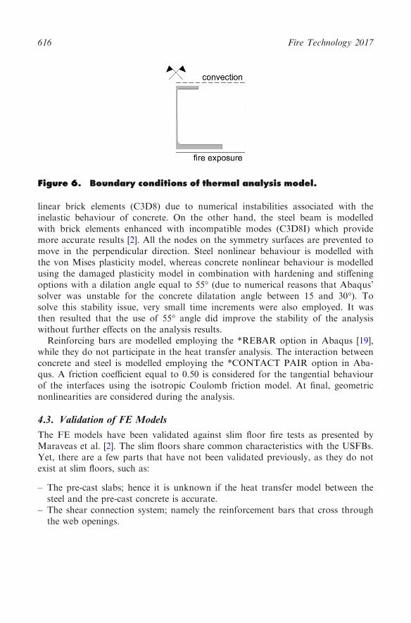
Three-dimensional (3D) heat transfer elements (DC3D8, 8-node linear bricks) areused for evaluating the thermal response of the USFBs. The temperature distribu-tion in the composite beam is predicted based on the standard fire curve (ISO834) [18]. A convection coefficient of 25 W/m2K is assumed for the exposed sur-face and 9 W/m2K for the unexposed one. The radiation emissivity for the lowersteel flange is taken to be 0.5 and for the concrete floor 0.25. The heat flow due toradiation is neglected for the upper side. The interface conductivity between con-crete and steel is considered as infinite (perfect thermal contact). No heat is trans-ferred normally to the symmetry axis. Heat is applied to the bottom surface of thecomposite beam and the radiation within the holes of the pre-casted slabs hasbeen considered. Figure 6 presents the thermal analysis boundary conditions.
4.2. Structural Analysis
Three-dimensional (3D) solid elements are used for evaluating the structuralresponse of USFB structural systems. The concrete slab is modelled with 8-node
Figure 5. Finite element models of the simulated USFBs (a) beam A,and (b) beam B.
Fire Resistance of Unprotected USFB 615
linear brick elements (C3D8) due to numerical instabilities associated with theinelastic behaviour of concrete. On the other hand, the steel beam is modelledwith brick elements enhanced with incompatible modes (C3D8I) which providemore accurate results [2]. All the nodes on the symmetry surfaces are prevented tomove in the perpendicular direction. Steel nonlinear behaviour is modelled withthe von Mises plasticity model, whereas concrete nonlinear behaviour is modelledusing the damaged plasticity model in combination with hardening and stiffeningoptions with a dilation angle equal to 55� (due to numerical reasons that Abaqus’solver was unstable for the concrete dilatation angle between 15 and 30�). Tosolve this stability issue, very small time increments were also employed. It wasthen resulted that the use of 55� angle did improve the stability of the analysiswithout further effects on the analysis results.
Reinforcing bars are modelled employing the *REBAR option in Abaqus [19],while they do not participate in the heat transfer analysis. The interaction betweenconcrete and steel is modelled employing the *CONTACT PAIR option in Aba-qus. A friction coefficient equal to 0.50 is considered for the tangential behaviourof the interfaces using the isotropic Coulomb friction model. At final, geometricnonlinearities are considered during the analysis.
4.3. Validation of FE Models
The FE models have been validated against slim floor fire tests as presented byMaraveas et al. [2]. The slim floors share common characteristics with the USFBs.Yet, there are a few parts that have not been validated previously, as they do notexist at slim floors, such as:
– The pre-cast slabs; hence it is unknown if the heat transfer model between thesteel and the pre-cast concrete is accurate.
– The shear connection system; namely the reinforcement bars that cross throughthe web openings.
Figure 6. Boundary conditions of thermal analysis model.
616 Fire Technology 2017
It is estimated that the above parts of the system do not significantly affect theanalyses presented in this paper, and this is because of the organic form of con-struction (Figures 1, 2) indicating how the effective area of concrete is acting withthe USFB. Therefore, no substantial slip between steel beam and concrete isexpected.
5. Numerical Results
5.1. Thermal Analysis
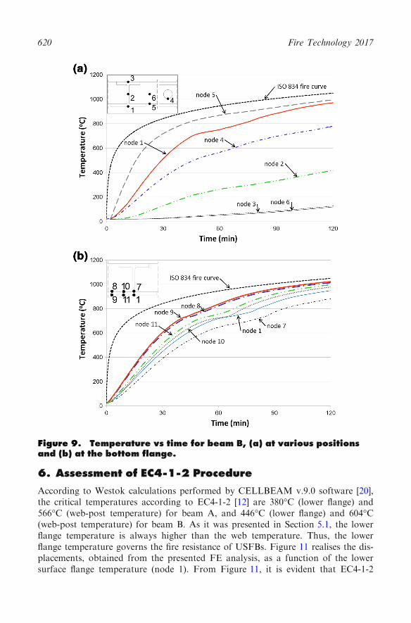
The results of thermal the analysis have been presented in Figures 7, 8 and 9. Theexposed bottom flange of the steel cross-section develops high temperatures. Forbeam A, due to low thickness, the temperature is almost uniform except of thearea near the web (nodes 1 and 2, Figure 8b), where the temperatures are lower asthe web is getting heated. For beam B, the thick bottom flange is heated slowlyand the temperature is not uniform (nodes 1 to 6, Figure 9b). The transport ofheat on the concrete surface (node 5) is affected by the heat coming from the steelflange at one side and the ISO fire curve at the bottom part. Also, due to the lowthermal conductivity of concrete, the temperature at node 5 is higher than thetemperature at node 1 (at bottom flange). As the thermal conductivity of steel ishigh, the web is getting hot too. The temperature at the mid-point of the webexceeds the 400�C after 110 min of exposure (node 2). The upper flange is notpractically affected (node 3) and it is not exceeding the 120�C even after 120 minof exposure. The temperature of the reinforcement (node 6) is always very low asit is well insulated from the concrete. The insulated by concrete web openings areaffecting the temperature distribution. The bottom edge of the opening (node 4) isdeveloping temperatures near the 600�C at 60 min of exposure although the upperedge of the openings is generally experienced low temperatures (Figure 7c). Theweb openings inside the pre-cast slab demonstrate similar effects (Figure 7b).
5.2. Structural Analysis
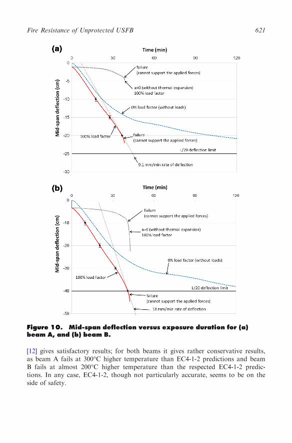
The results from the structural analysis are presented in Figure 10. It transpiresthat the limit of L/20 for the mid-span deflection and deflection rate limit of L2/(9000d) is exceeded in about 40 min at both beams. It should be noted that theexcess of the deflection rate limit is equivalent to the lost of the load bearingcapacity. Both beams also fail in bending at about 40 min of standard fire expo-sure. The effect of the load factor is important as the beams may have improvedfire resistance for reduced load factors (R60+).
From these results it is apparent that fire resistance is governed by the thermalexpansion of the lower flange, which develops very high temperatures contrary tothe rest of the section. The developing thermal gradients lead to beam bowing andlarge deflections, which limit the fire resistance.
Fire Resistance of Unprotected USFB 617
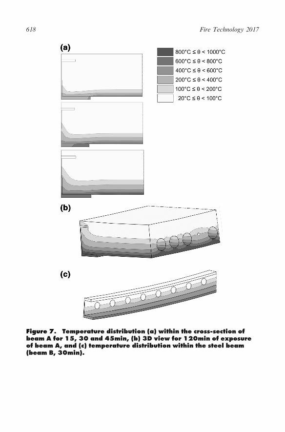
Figure 7. Temperature distribution (a) within the cross-section ofbeam A for 15, 30 and 45min, (b) 3D view for 120min of exposureof beam A, and (c) temperature distribution within the steel beam(beam B, 30min).
618 Fire Technology 2017

5.3. Sensitivity Analysis
In order to access the uncertainties of the used numerical model, a sensitivityanalysis has been performed for the parameters presented in Table 2. In everyanalysis only one parameter according Table 2 was modified, so eight analyses foreach beam were performed. The effect of these parameters has been presented inFigure 10 as error bars. The differences observed are minor and they do not affectthe overall behaviour.
Figure 8. Temperature vs time for beam A, (a) at various positionsand (b) at the bottom flange.
Fire Resistance of Unprotected USFB 619
6. Assessment of EC4-1-2 Procedure
According to Westok calculations performed by CELLBEAM v.9.0 software [20],the critical temperatures according to EC4-1-2 [12] are 380�C (lower flange) and566�C (web-post temperature) for beam A, and 446�C (lower flange) and 604�C(web-post temperature) for beam B. As it was presented in Section 5.1, the lowerflange temperature is always higher than the web temperature. Thus, the lowerflange temperature governs the fire resistance of USFBs. Figure 11 realises the dis-placements, obtained from the presented FE analysis, as a function of the lowersurface flange temperature (node 1). From Figure 11, it is evident that EC4-1-2
Figure 9. Temperature vs time for beam B, (a) at various positionsand (b) at the bottom flange.
620 Fire Technology 2017
[12] gives satisfactory results; for both beams it gives rather conservative results,as beam A fails at 300�C higher temperature than EC4-1-2 predictions and beamB fails at almost 200�C higher temperature than the respected EC4-1-2 predic-tions. In any case, EC4-1-2, though not particularly accurate, seems to be on theside of safety.
Figure 10. Mid-span deflection versus exposure duration for (a)beam A, and (b) beam B.
Fire Resistance of Unprotected USFB 621

7. Moment and Shear Capacity
7.1. Effect of Fire on the Moment Capacity of USFBs
When a steel–concrete composite beam is in equilibrium, the part of the steel sec-tion that is in tension produces a force equal to the resultant force of the concretecompressive stresses (to which are included the compressive stresses of the upperflange of the steel section and the reinforcement bars that nevertheless do not gov-ern the behaviour as strains are limited by the concrete), as it appears in Fig-ure 12a. When the steel section has a hole in the web, the tensile force is producedfrom the bottom tee-section, and it is equal to its cross section area multiplied bythe yield strength, is reduced by a corresponding safety factor (Figure 12b). Whena non-uniform temperature profile, with temperatures generally larger than 400�C,
Table 2Parameters Considered in the Sensitivity Analysis
Parameter Value
Thermal expansion model per EC4-1-2 [12]
Constant value [12]
per ASCE [22]
Element type C3D8
C3D8i
Dilation angle for concrete 15�30�55�
Figure 11. Displacement versus (node 1) bottom flange tempera-ture.
622 Fire Technology 2017
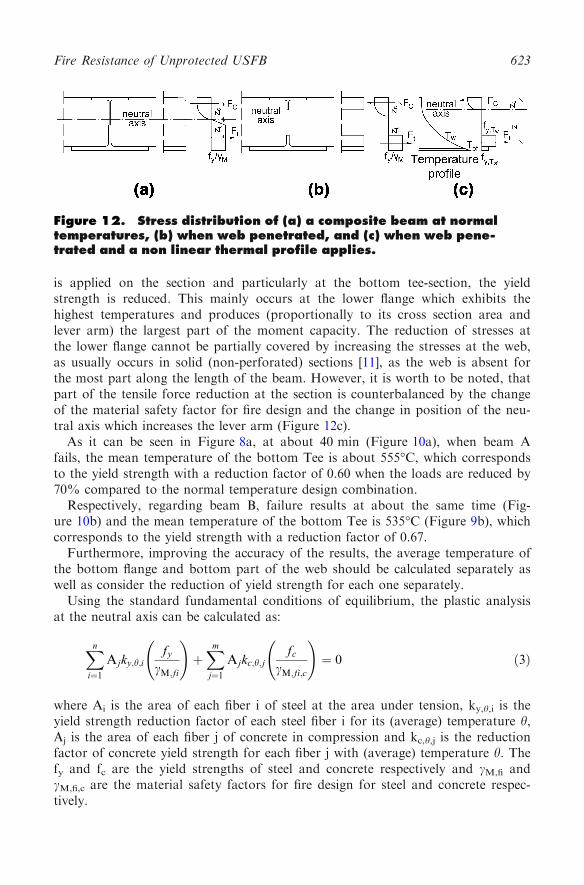
is applied on the section and particularly at the bottom tee-section, the yieldstrength is reduced. This mainly occurs at the lower flange which exhibits thehighest temperatures and produces (proportionally to its cross section area andlever arm) the largest part of the moment capacity. The reduction of stresses atthe lower flange cannot be partially covered by increasing the stresses at the web,as usually occurs in solid (non-perforated) sections [11], as the web is absent forthe most part along the length of the beam. However, it is worth to be noted, thatpart of the tensile force reduction at the section is counterbalanced by the changeof the material safety factor for fire design and the change in position of the neu-tral axis which increases the lever arm (Figure 12c).
As it can be seen in Figure 8a, at about 40 min (Figure 10a), when beam Afails, the mean temperature of the bottom Tee is about 555�C, which correspondsto the yield strength with a reduction factor of 0.60 when the loads are reduced by70% compared to the normal temperature design combination.
Respectively, regarding beam B, failure results at about the same time (Fig-ure 10b) and the mean temperature of the bottom Tee is 535�C (Figure 9b), whichcorresponds to the yield strength with a reduction factor of 0.67.
Furthermore, improving the accuracy of the results, the average temperature ofthe bottom flange and bottom part of the web should be calculated separately aswell as consider the reduction of yield strength for each one separately.
Using the standard fundamental conditions of equilibrium, the plastic analysisat the neutral axis can be calculated as:
Xn
i¼1
Ajky;h;ify
cM;fi
!þXm
j¼1
Ajkc;h;jfc
cM;fi;c
!¼ 0 ð3Þ
where Ai is the area of each fiber i of steel at the area under tension, ky,h,i is theyield strength reduction factor of each steel fiber i for its (average) temperature h,Aj is the area of each fiber j of concrete in compression and kc,h,j is the reductionfactor of concrete yield strength for each fiber j with (average) temperature h. Thefy and fc are the yield strengths of steel and concrete respectively and cM,fi andcL,fi,c are the material safety factors for fire design for steel and concrete respec-tively.
Figure 12. Stress distribution of (a) a composite beam at normaltemperatures, (b) when web penetrated, and (c) when web pene-trated and a non linear thermal profile applies.
Fire Resistance of Unprotected USFB 623
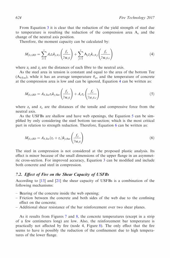
From Equation 3 it is clear that the reduction of the yield strength of steel dueto temperature is resulting the reduction of the compression area Ac and thechange of the neutral axis position.
Therefore, the moment capacity can be calculated by:
Mfi;t;RD ¼Xm
i¼1
Aiziky;h;ify
cM;fi
!þXm
j¼1
Ajzjkc;h;jfc
cM;fi;c
!ð4Þ
where zi and zj are the distances of each fibre to the neutral axis.As the steel area in tension is constant and equal to the area of the bottom Tee
(AbTee), while it has an average temperature hav and the temperature of concreteat the compression area is low and can be ignored, Equation 4 can be written as:
Mfi;t;RD ¼ Ab;Teeztky;havfy
cM;fi
!þ Aczc
fccM ;fi;c
!ð5Þ
where zt and zc are the distances of the tensile and compressive force from theneutral axis.
As the USFBs are shallow and have web openings, the Equation 5 can be sim-plified by only considering the steel bottom tee-section; which is the most criticalpart in relation to strength reduction. Therefore, Equation 6 can be written as:
Mfi;t;RD ¼ Ab;Teeðzt þ zcÞky;havfy
cM;fi
!ð6Þ
The steel in compression is not considered at the proposed plastic analysis. Itseffect is minor because of the small dimensions of the upper flange in an asymmet-ric cross-section. For improved accuracy, Equation 3 can be modified and includeboth concrete and steel in compression.
7.2. Effect of Fire on the Shear Capacity of USFBs
According to [13] and [21] the shear capacity of USFBs is a combination of thefollowing mechanisms:
– Bearing of the concrete inside the web opening;– Friction between the concrete and both sides of the web due to the confining
effect on the concrete;– Additional shear resistance of the bar reinforcement over two shear planes.
As it results from Figures 7 and 8, the concrete temperatures (except in a stripof a few centimeters long) are low. Also, the reinforcement bar temperature ispractically not affected by fire (node 4, Figure 8). The only effect that the fireseems to have is possibly the reduction of the confinement due to high tempera-tures of the lower flange.
624 Fire Technology 2017

From the above numerical models, it is not possible to assess the effect of fireon the shear capacity, as no shear failure occurred. In addition, the effect of hori-zontal shear was not assessed as the slip between the concrete and steel was notallowed in the numerical models. Given the complexity of this mechanism, furtherinvestigation is deemed necessary.
8. Conclusion
The paper presents a numerical investigation of the USFB behaviour in fire whenthe lower flange is unprotected. A hypothetical fire test simulation of two typicalUSFBs are demonstrated. The basic difference between the USFBs and otherflooring systems is that the web is penetrated and so it is unable to produce signif-icant moment capacity when the hot lower flange cannot provide sufficient tensileforce. The difference between penetrated and non-penetrated web beams dependson the web thickness. The beams without web penetration have shown increasedfire resistance, between 5 min and 15 min, compared with the penetrated webUSFBs. If the fire resistance of USFBs is compared with those of unprotectedbeams of same or similar cross-section thickness, the USFBs have considerablyimproved fire resistance as the unprotected beams may not exceed the 15 min.
In general, EC4-1-2 provides safe results for the fire resistance of such speci-mens; however USFB models with different slenderness and opening sizes need tobe examined. USFBs with unprotected lower flange have a fire resistance of R40and, as it was demonstrated, that is affected by the load factor and the deflection(thermal bowing). In order to improve the fire resistance of USFBs, the lowerflange must be protected so that bowing is avoided and temperatures are reduced.Alternatively, a lower load factor might be used (or a combination of the above).
Recommendations drawn by this study emphasise that a special attentionshould be given to conduct fire tests for extreme designs of USFBs with in-situ aswell as pre-cast slabs, in order to assess the extent of use of the current regulatedspecifications. Such fire tests can also be used to validate further detailed compu-tational models simulating slim floor steel–concrete flooring systems. Moreover, itis suggested that the shear connection systems should be assessed regarding theeffect of fire, and elevated temperature push-out tests should be conducted.
A series of experimental fire tests are prepared to be conducted at the Univer-sity of Ulster with those types of beams including all the structural details afterthe award of funding from the VCRS (Vice Chancellor Research Scholarshipaward for a PhD student). One of the integrated beams will have a solid web inorder to be used in the investigation and documentation of temperature profilesthrough the unprotected composite integrated beams. The experimental data willprovide the information to understand the strength loss before the failure andmechanisms of the failure modes, referential data for the calibration of the finiteelement models, and extended range of results; a solid basis for the definition ofdesign rules and constructional details.
Fire Resistance of Unprotected USFB 625

Acknowledgments
The authors of this work would like to thank ASD Westok ltd. and ASD MetalServices for the technical support in the development of the final design for theexamined USFB sections as well as for the supply of steel perforated specimensfor the subsequent experimental works. It is expected that the results from thisresearch study will be incorporated in Westok’s design software for USFBs(USFB-AutoMate) developed and certified by the Steel Construction Institute(SCI), updating the inherited fire design resistance of steel–concrete compositeUSFB sections. Further, the authors would like to accredit the University ofManchester for their support (covering Article Processing Charge).
Open Access
This article is distributed under the terms of the Creative Commons Attribution4.0 International License (http://creativecommons.org/licenses/by/4.0/), which per-mits unrestricted use, distribution, and reproduction in any medium, provided yougive appropriate credit to the original author(s) and the source, provide a link tothe Creative Commons license, and indicate if changes were made.
References
1. ASD Metal Services, Westok, Ultra Shallow Floor Beams,
http://www.kloecknermetalsuk.com/kloecknerwestok/usfb/. Accessed 21 Mar 20162. Maraveas C, Swailes T, Wang YC (2012) A detailed methodology for the finite element
analysis of asymmetric slim floor beams in fire. Steel Constr 5(3):191–1983. Maraveas C, Wang YC, Swailes T (2014) Fire resistance of 19th century fireproof floor-
ing systems: a sensitivity analysis. Constr Build Mater 55:69–814. Maraveas C (2014) Numerical analysis of DELTA composite beams in fire. In: 7th
European conference on steel and composite structures—EUROSTEEL
5. Bailey CG (1999) The behaviour of asymmetric slim floor steel beams in fire. J ConstrSteel Res 50:235–257
6. Newman GM (1995) Fire resistance of slim floor beams. J Constr Steel Res 33:87–100
7. Ma Z, Makelainen P (2000) Behaviour of composite slim floor structures in fire. JStruct Eng ASCE 126(7):830–837
8. Makelainen P, Ma Z (2000) Fire resistance of composite slim floor beams. J ConstrSteel Res 54:345–363
9. Ellobody E (2011) Nonlinear behaviour of unprotected composite slim floor steel beamsexposed to different fire conditions. Thin-Walled Struct 49:762–771
10. Both C, Fellinger JHH, Twilt L (1997) Shallow floor construction with deep composite
deck: from fire tests to simple calculation rules. Heron 42(3):145–15811. Maraveas C, Wang YC, Swailes T (2016) Moment capacity of cast iron beams exposed
to fire. In: Proceedings of ICE: structures and buildings. doi:10.1680/jstbu.15.00120
12. EN 1994-1-2 (2005) Eurocode4—design of composite steel and concrete struc-tures—part 1-1: design for fire, CEN, Brussels
626 Fire Technology 2017
13. Tsavdaridis KD, D’Mello C, Huo BY (2013) Experimental and computational study ofvertical shear behaviour of partially encased perforated steel beams. J Eng Struct56:805–822
14. Yu Huo B, D’Mello C, Tsavdaridis KD (2010) Experimental and analytical study ofpush-out shear tests in ultra shallow floor beams. In: 34th international association forbridge and structural engineering (IABSE) symposium, Venice, Italy, pp 31–38
15. Tsavdaridis KD, Giaralis A (2011) Derivation of dynamic properties of steel perforated
ultra shallow floor beams (USFB) via finite element modal analysis and experimentalverification. The 7th national conference on steel structures, Volos, Greece, vol 2, pp321–329
16. Tsavdaridis KD, D’Mello C, Hawes M (2009) Experimental study of ultra shallow floorbeams (USFB) with perforated steel sections. Nordic Steel Construction Conference2009, NSCC2009. 2–4 September 2009, Malmo, Sweden, Reference no. 128, pp 312–319
17. EN 1991 (2002) Eurocode 1—actions on structures—part 1–2: general actions—actionson structures exposed to fire. CEN Brussels
18. ISO 834–1 (1999) Fire-resistance tests—elements of building construction—part 1: gen-eral requirements. ISO, Switzerland
19. Abaqus v6.11 (2012) User manual, Simulia20. Cellbeam v.9.0.0 (2013) User manual, westok/SCI21. Enchanced design of ultra shallow floor beams, New Steel Construction, June 2011, pp
30–3122. Kodur V, Dwaikat M, Fike R (2010) High-temperature properties of steel for fire resis-
tance modeling of structures. J Mater Civ Eng ASCE 22(5):423–434
Fire Resistance of Unprotected USFB 627


