Fire Performance of Glass Curtain Wall · PDF filei Fire Performance of Glass Curtain Wall A...
105
i Fire Performance of Glass Curtain Wall A Major Qualifying Project Submitted to the Faculty of Worcester Polytechnic Institute in partial fulfillment of the requirements for the Bachelor of Science Approved by: Submitted by: Joycelyn De La Rosa and Yijie Lu
-
Upload
nguyentram -
Category
Documents
-
view
215 -
download
0
Transcript of Fire Performance of Glass Curtain Wall · PDF filei Fire Performance of Glass Curtain Wall A...
i
Fire Performance of Glass Curtain Wall
A Major Qualifying Project
Submitted to the Faculty of Worcester Polytechnic Institute
in partial fulfillment of the requirements for the Bachelor of Science
Approved by:
Submitted by:
Joycelyn De La Rosa and Yijie Lu

ii
Abstract For this Major Qualifying Project (MQP) a virtual simulation of the fire-resistance test
ASTM E 2307 for an glass curtain wall system was created using computer software ANSYS. Using
the software, knowledge was gained on the thermal and structural performance of these
structures during a fire. Information from building codes such as the Uniform Building Code,
Standards Building Code, BOCA National Building Code, the International Building Code and
Underwriters Laboratories also allowed for the understanding of the fire-resistance of a curtain
wall. Together, the codes and the virtual simulation support in determining whether there is a
need for certain per-requisites such as, a 3-foot spandrel inside a curtain wall or having an
automatic sprinkler system installed that are reference in the building codes.
iii
Acknowledgements We want to give a thank you to all those how helped us in completing this Major
Qualifying Project. To Brian Kuhn and Joshua Kivela from Simpson, Gumpertz, and Heger for
providing us with the idea for this project. As well as, allotting us with resources to aid in the
research portion of this project. A special thank you to both of our advisors Professor Steven Van
Dessel and Professor Ali Fallahi, both of whom have been trivial in the completion of project.
They provided us with the knowledge and encouragement to do the work necessary. Once again,
thank you!
iv
Table of Contents Abstract ............................................................................................................................................ii
Acknowledgements ......................................................................................................................... iii
Table of Figures ............................................................................................................................... vi
Table of Tables .............................................................................................................................. viii
Executive Summary ......................................................................................................................... 1
1. Introduction ............................................................................................................................. 3
2. Background .............................................................................................................................. 6
2.1 History of Building Code ......................................................................................................................... 6
2.1.1 Uniform Building Code (UBC) ....................................................................................................... 7
2.1.2 Standard Building Code (SBC) ...................................................................................................... 7
2.1.3 BOCA National Building Code (BOCA/NBC) ................................................................................. 7
2.1.4 International Building Cod (IBC) ................................................................................................... 8
2.2 Modern Code Usage ............................................................................................................................. 10
2.2.1 Underwriters Laboratories (UL) Listing ...................................................................................... 11
3. Review of Relevant Codes and Standards ............................................................................. 13
3.1 IBC ......................................................................................................................................................... 13
3.2 Standards .............................................................................................................................................. 13
3.3 ASTM E2307 .......................................................................................................................................... 14
3.3.1 Test Set Up ................................................................................................................................. 16
3.3.2 Results: ....................................................................................................................................... 19
3.4 ASTM E 119 ........................................................................................................................................... 19
4. Methodology ......................................................................................................................... 21
4.1 ANSYS .................................................................................................................................................... 21
4.1.1 Structural Performance .............................................................................................................. 21
4.1.2 Thermal Performance ................................................................................................................ 22
4.1.3 Combination of Structural and Thermal Performance .............................................................. 23
4.2 Curtain Wall Model ......................................................................................................................... 25
4.2.1 2D Auto CAD............................................................................................................................... 27
4.2.2 2D ANSYS: Set-Up ....................................................................................................................... 29
4.2.3 2D ANSYS: Combined Thermal and Structural Set-Up ............................................................... 31
4.2.4 3D Auto CAD............................................................................................................................... 33
v
4.2.5 3D ANSYS: Set-Up ....................................................................................................................... 37
4.2.6 3D ANSYS: Thermal Set-Up ........................................................................................................ 41
4.2.7 3D ANSYS: Structural Set-Up ...................................................................................................... 42
5. Results ....................................................................................................................................... 43
5.1 Thermal Results ..................................................................................................................................... 43
5.2 Structural............................................................................................................................................... 45
5.3 Thermal & Structural ............................................................................................................................. 48
6. Parametric Test ......................................................................................................................... 50
6.1 Wind Loads ............................................................................................................................................ 51
6.2 Movement of Fire ................................................................................................................................. 53
6.3 Results ................................................................................................................................................... 54
7. Conclusion ................................................................................................................................. 56
7.1 Future Consideration ............................................................................................................................ 56
Appendix A: Data .......................................................................................................................... 59
Parametric Data: Wind loads ...................................................................................................................... 61
Parametric Data: Fire Movement ............................................................................................................... 71
Appendix B: User’s Guide ............................................................................................................. 77
Work Cited .................................................................................................................................... 97

vi
Table of Figures Chapter 1 Figure 1.1: Curtain Wall Representation of Fire Resistive Joint and Perimeter Barrier ................. 3
Chapter 2 Figure 2.1: Building Code ................................................................................................................ 6
Figure 2.2: Typical Glass Curtain Wall with elements defined ..................................................... 11
Chapter 3 Figure 3.1: Actual Performance of ASTM E 2307 .......................................................................... 15
Figure 3.2: Plan View of Test Room Burner Positioned in Test Room ......................................... 17
Figure 3.3: Plan View of Window Burner and Side Elevation View of Window Burner Location 18
Figure 3.4: Examples of Exterior Wall Assembly with Window Openings .................................... 19
Figure 3.5: ASTM E 119 Time-Temperature Curve with Material Examples ................................ 20
Chapter 4 Figure 4.1: Structural Problem of Fixed Beam .............................................................................. 22
Figure 4.2: Structural Performance of Fixed Beam....................................................................... 22
Figure 4.3: Thermal Performance of Shell .................................................................................... 23
Figure 4.4: Thermal Performance of Specimen ............................................................................ 23
Figure 4.5: Simple Fixed Beam between two Walls...................................................................... 24
Figure 4.6: Thermal Result ............................................................................................................ 24
Figure 4.7: Structural Result ......................................................................................................... 24
Figure 4.8: HILTI Curtain Wall ....................................................................................................... 25
Figure 4.9: 2D ANSYS of Glass Curtain in ISMA ............................................................................ 26
Figure 4.10: 3D ANSYS of Glass Curtain in ISMA .......................................................................... 27
Figure 4.11: 2D Auto CAD of HILTI Model .................................................................................... 28
Figure 4.12: Custom System – Thermal-Structural ...................................................................... 29
Figure 4.13: 3D Auto CAD of HILTI Model .................................................................................... 34
Figure 4.14: 2D HILTI Model with Dimensions ............................................................................. 35
Figure 4.15: Zoomed in Connection between Concrete and Mullion .......................................... 35
vii
Figure 4.16: L-bracket connection between mullions .................................................................. 36
Figure 4.17: Meshing of Curtain Wall ........................................................................................... 40
Figure 4.18: Zoomed in Meshing of Joint Connect of Curtain Wall .............................................. 40
Figure 4.19: 3D ANSYS Curtain Wall ............................................................................................. 41
Chapter 5 Figure 5.1: Transient Thermal Results: Temperature .................................................................. 44
Figure 5.2: Graphical - Transient Thermal Results: Temperature ............................................... 44
Figure 5.3: Transient Thermal Results: Heat Flux ........................................................................ 44
Figure 5.4: Graphical - Transient Thermal Results: Heat Flux ...................................................... 45
Figure 5.5: Static Structural Results: Total Deformation ............................................................. 46
Figure 5.6: Static Structural Results: Equivalent Elastic Strain .................................................... 47
Figure 5.7: Static Structural Results: Equivalent Stress ............................................................... 47
Figure 5.8: Combined Thermal and Structural Results: Total Deformation ................................. 49
Figure 5.9: Graphical – Max and Min Deformation: Combined ................................................... 49
Figure 5.10: Graphical –Min Deformation: Combined ................................................................ 49
Chapter 6 Figure 6.1: Total Deformation: 1st Floor, Only Wind Pressure ..................................................... 51
Figure 6.2: Graphical – Max Deformation: Wind Pressure .......................................................... 52
Figure 6.3: Total Deformation: 2ft Away, Only Fire ..................................................................... 53
Figure 6.4: Graphical – Max Deformation: Fire Movement ......................................................... 54
Figure 6.5: Graphical - Total Deformation: Wind Pressure and Fire Movement ......................... 55
viii
Table of Tables Chapter 3 Table 3.1: IBC 2015 Table 1604.3 Deflection Limits .................................................................... 13
Chapter 4 Table 4.1: 2D Geometry Materials and their Thermal Properties ................................................ 30
Table 4.2: 2D Geometry Connections between Elements ............................................................ 31
Table 4.3: 2D Geometry Number of Faces and Node Sizing ......................................................... 31
Table 4.4: Radiation – Tabular Data .............................................................................................. 32
Table 4.5: Fire Temperature – Tabular Data ................................................................................. 32
Table 4.6: Wind Pressure – Tabular Data ..................................................................................... 33
Table 4.7: 3D Geometry Materials and their Thermal Properties ................................................ 38
Table 4.6: Aluminum Alloy – Tabular Data ................................................................................... 38
Table 4.9: 3D Geometry Connections between Elements ............................................................ 39
Table 4.10: Surface to Surface Radiation ...................................................................................... 41
Table 4.11: 3D Geometry Structural Boundary Conditions and Properties ................................. 42
Chapter 5 Table 5.1: Time vs Deflection: Max and Min ............................................................................... 50
Chapter 6 Table 6.1: Total Deformation: 1st Floor, Only Wind Pressure ...................................................... 52
Table 6.2: Max Deformation: Wind Pressure .............................................................................. 52
Table 6.3: Total Deformation: 2ft Away, Only Fire ...................................................................... 54
Table 6.4: Max Deformation: Fire Movement ............................................................................. 54
Table 6.5: Total Deformation: Wind Pressure and Fire Movement ........................................................... 55
1
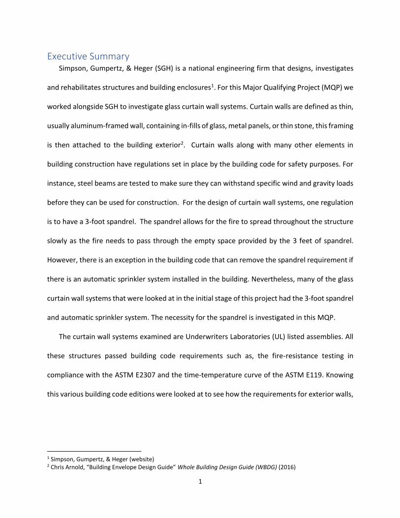
Executive Summary Simpson, Gumpertz, & Heger (SGH) is a national engineering firm that designs, investigates
and rehabilitates structures and building enclosures1. For this Major Qualifying Project (MQP) we
worked alongside SGH to investigate glass curtain wall systems. Curtain walls are defined as thin,
usually aluminum-framed wall, containing in-fills of glass, metal panels, or thin stone, this framing
is then attached to the building exterior2. Curtain walls along with many other elements in
building construction have regulations set in place by the building code for safety purposes. For
instance, steel beams are tested to make sure they can withstand specific wind and gravity loads
before they can be used for construction. For the design of curtain wall systems, one regulation
is to have a 3-foot spandrel. The spandrel allows for the fire to spread throughout the structure
slowly as the fire needs to pass through the empty space provided by the 3 feet of spandrel.
However, there is an exception in the building code that can remove the spandrel requirement if
there is an automatic sprinkler system installed in the building. Nevertheless, many of the glass
curtain wall systems that were looked at in the initial stage of this project had the 3-foot spandrel
and automatic sprinkler system. The necessity for the spandrel is investigated in this MQP.
The curtain wall systems examined are Underwriters Laboratories (UL) listed assemblies. All
these structures passed building code requirements such as, the fire-resistance testing in
compliance with the ASTM E2307 and the time-temperature curve of the ASTM E119. Knowing
this various building code editions were looked at to see how the requirements for exterior walls,
1 Simpson, Gumpertz, & Heger (website) 2 Chris Arnold, “Building Envelope Design Guide” Whole Building Design Guide (WBDG) (2016)

2
specifically curtain walls, change over time. Research was put into understanding the function
and data provided by ASTM E2307 and ASTM E119.
The goal of this MQP is to study the need for the 3-foot spandrel. To do this a HILTI curtain
wall model without a spandrel is used in a virtual simulation of the Intermediate-Scale Multi-
Story Apparatus (ISMA) that is utilized in the ASTM E2307: fire resistance test. The creation of
this virtual apparatus with computer software such as ANSYS gives understanding to what a
curtain wall system goes through first hand when put under the conditions of fire and loading.
The thermal and structural performance of the curtain wall is tested to see the failure of materials
and the times at which these failures occur. Further testing is put into the apparatus to view the
effects fire and wind loads have on the system. For instance, moving the fire closer or further
away from the vision glass may influence the failure/deformation of the material. If the apparatus
is on the 10th floor and not the 1st floor, the wind loads may be effected and in turn might affect
the fire and failure/deformation of the curtain wall materials. The parameters that are
questioned are put to the test. The results garnered from the simulation are compared to the
actual results from the ASTM E 2307 and ultimately show if the HILTI model used passes the test
or requires the 3-foot spandrel.
3
1. Introduction The possibility of a fire is a major concern when constructing a building. To protect those who
inhabit these structures specific attention is paid to the fire-resistance of the building materials.
High-rise buildings that use a glass exterior façade, curtain wall systems have a low fire-resistance
rating and as a result, elements such as a 3-foot spandrels and/or automatic sprinkler systems
are used to increase the fire-resistance rating. These elements allow the fire to spread slowly
throughout the building, giving time for those inside to evacuate before the building materials
start to fail and collapse.
If a fire were to break out in a high-rise building the spread of fire would be vertical, going
from one floor to the next, following with the flow of air currents. This is because the void
between the floor and curtain wall are not properly sealed. The fire will affect both sides of the
curtain wall system causing premature failure of the wall and potentially the vision glass
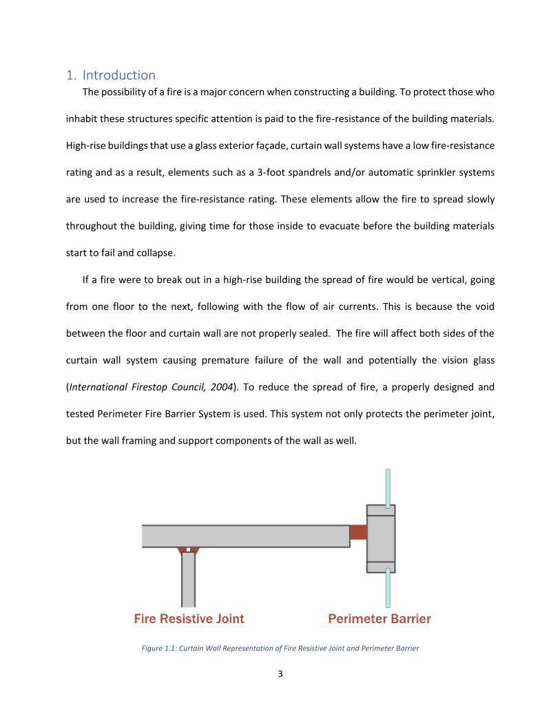
(International Firestop Council, 2004). To reduce the spread of fire, a properly designed and
tested Perimeter Fire Barrier System is used. This system not only protects the perimeter joint,
but the wall framing and support components of the wall as well.
Figure 1.1: Curtain Wall Representation of Fire Resistive Joint and Perimeter Barrier

4
Protecting the perimeter also requires the extension of the rated floor to the exterior wall
surface. The Perimeter Fire Barrier System, the sealing of the perimeter joint, and extension of
the rated floor provides structural protection and maximizes the integrity of the wall system. This
can keep the wall and window system intact for a longer period of time. Other benefits of these
precautions include:
Forcing the fire to exit the building
Preventing the movement of flames, hot gases and smoke to the floors above
Protecting the structural elements and helps prevent failure of spandrel system
Maximizing fire protection of non-fire rated walls
Giving time for occupants to evacuate and first responders to secure the building
Providing additional protection if sprinklers or fire alarms fail
To test the integrity of a glass curtain wall and it’s perimeter fire barrier an Intermediate-
Scale Multi-Story Apparatus (ISMA) is used. This scheme is referenced in the more recent editions
of the IBC and is performed in accordance to ASTM E2307: Fire-Resistance Test. This test
determines two ratings: “F”-rating3, the resistance to fire spread and “T”-rating4, the
temperature on non-fire side. Further understanding of this test permits the knowledge to use
and design curtain wall systems that are structurally sound when withstanding loads such as,
wind and gravity, and being able to sustain itself during extreme conditions such as fire.
3 The "F Rating" is a measure of the perimeter-fire-containment system to limit flame penetration through
the system or around its boundaries and the passage of flames and hot gases sufficient to ignite cotton waste as defined in ANSI/ASTM E2307 (UL Online Certification Directory) 4 The "T Rating" is a measure of the ability of the perimeter-fire-containment system to limit the temperature
rise on the unexposed surface of the perimeter-fire-containment system and the adjacent supporting construction as defined in ANSI/ASTM E2307 (UL Online Certification Directory)

5
For this Major Qualifying Project, the problem that is to be solved is the inevitability of
the 3-foot spandrel to increase the fire-resistance of a curtain wall system. To do this, an initial
study of the effects fire has on the thermal and structural performance of a non-spandrel curtain
wall model has to be done. Research is put into the different building code requirements, taking
into consideration constraints for exterior walls, curtain walls, spandrels, and fire protection.

6
2. Background To recognize why certain requirements are put in place during the construction process of a
curtain wall system, one should consider the different building codes used. This is to know how
these construction constraints might have changed over time and the differences that were made
to the erection and/or instillation of that system. The codes that were looked at in this project
include the Uniform Building Code, Standard Building Code, BOCA National Building Code, and
the International Building Code. With each edition of the different codes the requirements for
exterior walls, curtain walls and fire protection change slightly, staying current with any
construction/ engineering advancements.
2.1 History of Building Code
Figure 2.1: Building Code in the United States
The building code for engineers, contractors, and architects goes back about 90 years and
went from three individual codes separated by region i.e. Northeast, South, and Midwest to one
cohesive code. The first of the building codes were the Uniform Building Codes (UBC), then the
Standard Build Codes (SBC), and finally BOCA National Building Codes (BOCA/NBC). The three
organizations that created these codes came together to create the International Building Code

7
(IBC) which meets many the requirements set forth by the codes before them, with the addition
of other prerequisites as times have changed and advancements are made.
2.1.1 Uniform Building Code (UBC)
The UBC were codes for the Mid-West part of the United States. The International
Conference of Building Official’s (ICBO) developed these codes. For these codes, there was
mention of exterior walls needing to maintain a fire resistive rating if they were passing through
an attic. The UBC provided its own table for these fire resistance rating of exterior walls. Later
versions of the UBC also mention construction joints needing to be used in fire resistant walls to
protect an opening in the wall. However, the editions of the code looked at by the team had no
mention of curtain walls or spandrel requirements.
2.1.2 Standard Building Code (SBC)
The SBC was a set of regulations enacted by the Southern Building Code Congress
International (SBCCI) in 1945. These code requirements dealt with southern states such as,
Alabama, Georgia, and Florida. The primary focus of these codes was to protect the life, health,
and welfare of the building environment. Though these codes played an important role in
southern states, a find full versions of the code could not be found to understand how southern
states dealt with exterior walls/curtain walls and its thermal and structural performance.
2.1.3 BOCA National Building Code (BOCA/NBC)
BOCA National Building Codes were established in the 1950s for construction in the
Northeast and Mid-West by the nonprofit organization Building Official’s and Code Administrator
International (BOCA), which was established in 1915. The parameters set forth by this
organization in accordance to Fire Protection and Curtain wall system requirements include
section 902.1.1 Fire resistance Rating.

8
902.1.1 Fire Resistance-Rating: The fire resistance properties of materials and
assemblies must be measured and specified according to a common test standard. For
this reason, the fire resistance rating of building assemblies and structural elements shall
be determined in accordance to ASTM E 119 5(BOCA, 1990)
The ASTM E119 is pivotal in building assemblies and is stilled used to determine the fire-
resistance rating of materials and structures. The ASTM E119 test provides a time-temperature
curve that is used to see when a material in a curtain wall system or any other type of building
assembly were to fail. If the material were to collapse before the time and temperature
previously established by the curve, then the assembly or material should not be used.
Besides the mention of the ASTM E119, there is no reference to curtain wall systems or
spandrel opening in the code editions that were found. There was also no reference to the ASTM
E2307 test.
2.1.4 International Building Cod (IBC)
The International Building Code was developed in 2003 and takes into consideration the
requirements that were set in place by the previous building codes. The first edition of the code
had similar requirements to UBC for exterior wall systems however; later versions of the IBC do
mention curtain wall systems and the need for a 3-foot spandrel.
705.8.5 Vertical separation of opening: Openings in exterior walls in adjacent stories shall
be separated vertically to protect against fire spread on the exterior of the buildings
where the openings are within 5 feet (1524 mm) of each other horizontally and the
opening in the lower story is not a protected opening with a fire protection rating of not
less than 3/4 hour. Such openings shall be separated vertically not less than 3 feet (914
mm) by spandrel girders, exterior walls or other similar assemblies that have a fire-
resistance rating of not less than 1 hour
Exceptions:
5 Test method that evaluates the ability of an assembly to contain a fire or to retain its structural integrity, or both, in terms of endurance time during the testing conditions (BOCA, 1990)

9
1. This section shall not apply to buildings that are three stories or less
above grade plane.
2. This section shall not apply to buildings equipped throughout with
an automatic sprinkler system in accordance with Section
903.3.1.1 or 903.3.1.2.
3. Open parking garages.
- IBC, 2015
In this section of the IBC, the 3-foot spandrel is used to allow for a fire-resistance rating 6of at
least an hour. The minimum fire-resistance rating of 1 hour allows for appropriate protection of
the system7 because it gives people enough time to exit a building before the materials start to
fail and the structure collapses. The exception to the rule, having a sprinkler system installed, is
mentioned in this section of the IBC. The sprinkler system is used as precaution; if a fire were to
start in a structure the sprinklers will go off to try to minimize the fire, giving those who inhabit
the structure time to exit.
The IBC also references ASTM E2307 in section 715.4: Exterior Curtain Wall/Floor
Intersection. The section goes into detail about the different rating provided by the ASTM E2307
as well as, exception to this rule.
715.4 Exterior curtain wall/floor intersection: Where fire resistance-rated floor or
floor/ceiling assemblies are required, voids created at the intersection of the exterior
curtain wall assemblies and such floor assemblies shall be sealed with an approved system
to prevent the interior spread of fire. Such systems shall be securely installed and tested
in accordance with ASTM E2307 to provide an F rating for a time period not less than
the fire-resistance rating of the floor assembly. Height and fire-resistance requirements
for curtain wall spandrels shall comply with Section 705.8.5.
Exception: Voids created at the intersection of the exterior curtain wall assemblies
and such floor assemblies where the vision glass extends to the finished floor level
shall be permitted to be sealed with an approved material to prevent the interior
6 Fire-resistance rating: the duration for which a passive fire protection system can withstand a standard fire resistance test, is quantified as a measurement of time 7 Arthur J. Parker and Jesse J. Beitel, Required Fire Resistance Ratings for Structural Building Elements, SFPE
10
spread of fire. Such material shall be securely installed and capable of preventing
the passage of flame and hot gases sufficient to ignite cotton waste where
subjected to ASTM E119 time-temperature fire conditions under a minimum
positive pressure differential of 0.01 inch (0.254 mm) of water column (2.5 Pa) for
the time period not less than the fire-resistance rating of the floor assembly
- IBC, 2015
In this portion of the code, floor or floor/ceiling assemblies such as curtain walls are required to
have an approved system that is installed and tested in accordance to ASTM E2307. This test
provides an F rating8 for various time periods; the rating should be at least equal to the fire-
resistance rating of the floor assembly (IBC, 2012). If the material fails to do so, it cannot be used
for the assembly of a curtain wall.
The requirements set in place by these two sections of the code allowed for greater
understanding of curtain wall system design. It also provides a stepping-stone for this Major
Qualifying Project.
2.2 Modern Code Usage In addition to researching building codes, other documentation that deemed a curtain
wall safe for use were considered. The Underwriters laboratories documentation for certification
of safety helped in determining the type of curtain wall modeled for the schematic. Underwriter
Laboratories is a company that conducts safety analysis for new technologies such as electrical
appliances and curtain wall system. UL provides safety certification through precautions such as
testing and inspection. If the system passes the necessary testing and other requirements it
receives the UL seal of approval for use. The testing required for curtain wall systems will be
discussed in the next few paragraphs.
8 F-rating: Flame rating - expressed in hours and the number indicates the specific length of time that a barrier can withstand fire before being consumed or before permitting the passage of flame through the opening (ASTM E814)
11
2.2.1 Underwriters Laboratories (UL) Listing
To gain the certification of the Underwriters Laboratory (UL) the curtain walls go through
specific test. One of the test contains a perimeter-fire-containment system, Intermediate-Scale
Multi-Story Apparatus (ISMA), it is particular to constructions consisting of a floor with an hourly
fire-resistance rating, an exterior curtain wall with no hourly fire-resistance rating, and material
installed to fill gaps between the floor and the curtain wall to prevent the vertical spread of fire
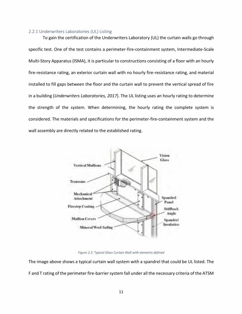
in a building (Underwriters Laboratories, 2017). The UL listing uses an hourly rating to determine
the strength of the system. When determining, the hourly rating the complete system is
considered. The materials and specifications for the perimeter-fire-containment system and the
wall assembly are directly related to the established rating.
Figure 2.2: Typical Glass Curtain Wall with elements defined
The image above shows a typical curtain wall system with a spandrel that could be UL listed. The
F and T rating of the perimeter fire-barrier system fall under all the necessary criteria of the ATSM

12
E2307 to be certified. It also is in compliance with the UL 2079, an additional criterion for
certification that provides the integrity rating and the insulation rating using the same apparatus,
ISMA.
These ratings go hand in hand to attest to a structurally sound curtain wall system. The
standards for the Integrity Rating complies with the requirements for the “F-rating”. It also limits
the passage of flams through openings in the curtain wall above the perimeter fire barrier (UL
Online Certification Directory). For the Insulation Rating it complies with the “T-Rating” and it also
limits the temperature rise to 325 F above the starting temperature in the interior surface of the
curtain wall (UL Online Certification Rating).
The Underwriters laboratories also takes into consideration the Leakage Rating (L-Rating)
that measures the amount of air leakage through the perimeter-fire-containment system. Using
NFPA 101 “Life and Safety Code” as a parameter to determine the stability of the system to
restrict the movement of smoke throughout a building (UL Online Certification Rating). However,
the virtual simulation created for this MQP is a simplified version of the perimeter-fire-
containment system, taking only into consideration the only the “F-Ratings” and “T-Ratings”. To
take into consideration air leakage would require the knowledge of the fluids parameter in ANSYS
which could not be adequately learned in the amount of time required to complete this project.
Nevertheless, the two ratings, F and T, that is given with the HILTI curtain wall model
schematic provided a simulation that was able to function and give readings for the thermal and
structural performance.
13
3. Review of Relevant Codes and Standards Other parameter like the F-Rating and T-Rating were found through the review of relevant
codes and standards. The deflection limit for mullion system as well as, maximum wind pressure
and other loadings that are applied to a high-rise building when put under conditions of the Fire
Resistance Test. These parameters gave further understanding of what to expect when creating
and analyzing the virtual simulation of the Fire Resistance Test modeled in ANSYS.
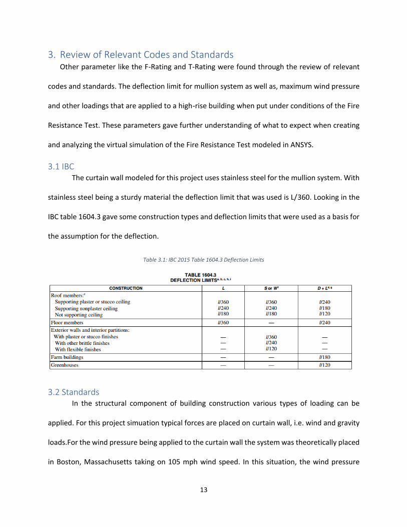
3.1 IBC The curtain wall modeled for this project uses stainless steel for the mullion system. With
stainless steel being a sturdy material the deflection limit that was used is L/360. Looking in the
IBC table 1604.3 gave some construction types and deflection limits that were used as a basis for
the assumption for the deflection.
Table 3.1: IBC 2015 Table 1604.3 Deflection Limits
3.2 Standards In the structural component of building construction various types of loading can be
applied. For this project simuation typical forces are placed on curtain wall, i.e. wind and gravity
loads.For the wind pressure being applied to the curtain wall the system was theoretically placed
in Boston, Massachusetts taking on 105 mph wind speed. In this situation, the wind pressure
14
being utilized on the structure is 8.35 psf. The number was calculated by using the Cornell
University Wind Pressure Calculator by Jonathan Ochshorn. This calculator took into account the
city, giving a constant wind speed of 105 mph, and the roof height. Other parameters in the
calculator remained unchanged resulting in a wind pressure of 8.35 psf. This calculator though
not intended for actual design purposes did give understanding of design principals. As for the
gravity load the standard value for gravity, 386 in/s2 is used. The parameters found through
research allows for the simulation to mimic that of the real world.
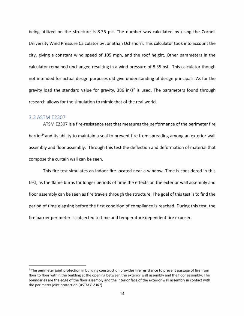
3.3 ASTM E2307 ATSM E2307 is a fire-resistance test that measures the performance of the perimeter fire
barrier9 and its ability to maintain a seal to prevent fire from spreading among an exterior wall
assembly and floor assembly. Through this test the deflection and deformation of material that
compose the curtain wall can be seen.
This fire test simulates an indoor fire located near a window. Time is considered in this
test, as the flame burns for longer periods of time the effects on the exterior wall assembly and
floor assembly can be seen as fire travels through the structure. The goal of this test is to find the
period of time elapsing before the first condition of compliance is reached. During this test, the
fire barrier perimeter is subjected to time and temperature dependent fire exposer.
9 The perimeter joint protection in building construction provides fire resistance to prevent passage of fire from floor to floor within the building at the opening between the exterior wall assembly and the floor assembly. The boundaries are the edge of the floor assembly and the interior face of the exterior wall assembly in contact with the perimeter joint protection (ASTM E 2307)

15
Conditions of compliance include:
Movement Cycling Test10 Perimeter joint11 protection completes at least the minimum movement cycle for the movement type selected
Fire-Resistance Test T-Rating of perimeter fire barrier should be determined when conditions such as, the temperature unexpectant rises more than 375F from its original temperature, first occurs
Integrity Test The perimeter fire barrier should not allow for fames or hot gases to pass and ignite insulation
Load Application The perimeter joint of protection should be able to withstand the load being applied during the rating period
The fire exposer conditions used for this test are specified in the first 30 minutes of fire exposer.
Then the time-temperature curve from ASTM E119, which will be discussed later, is used for the
remained of the test.
Figure 3.1: Actual Performance of ASTM E 2307 Test
10 Movement cycle – the change between the minimum and the maximum joint width 11 The linear void located between a juxtaposed exterior wall and assembly and floor assembly to accommodate various movements of the floor and wall during construction (ASTM E 2307)
16
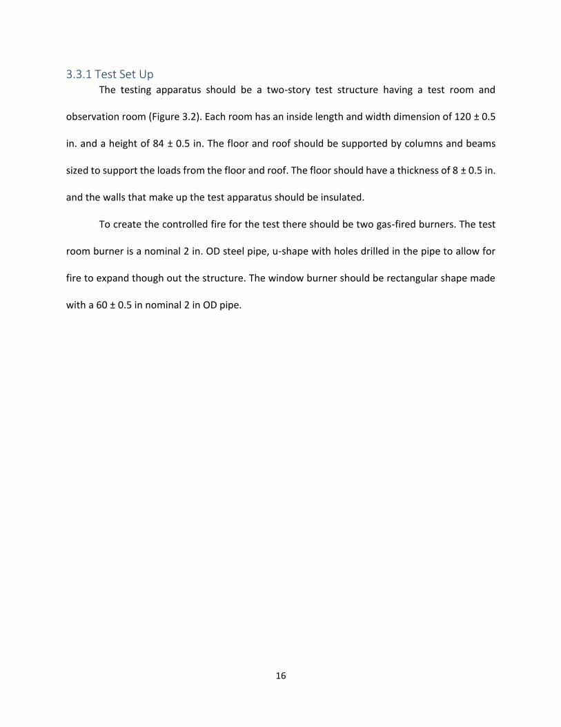
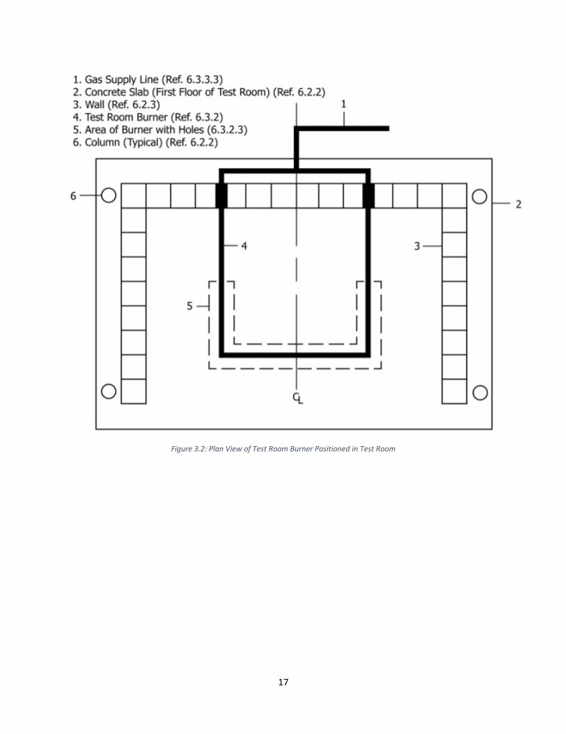
3.3.1 Test Set Up The testing apparatus should be a two-story test structure having a test room and
observation room (Figure 3.2). Each room has an inside length and width dimension of 120 ± 0.5
in. and a height of 84 ± 0.5 in. The floor and roof should be supported by columns and beams
sized to support the loads from the floor and roof. The floor should have a thickness of 8 ± 0.5 in.
and the walls that make up the test apparatus should be insulated.
To create the controlled fire for the test there should be two gas-fired burners. The test
room burner is a nominal 2 in. OD steel pipe, u-shape with holes drilled in the pipe to allow for
fire to expand though out the structure. The window burner should be rectangular shape made
with a 60 ± 0.5 in nominal 2 in OD pipe.
17
Figure 3.2: Plan View of Test Room Burner Positioned in Test Room

18
Figure 3.3: Plan View of Window Burner and Side Elevation View of Window Burner Location
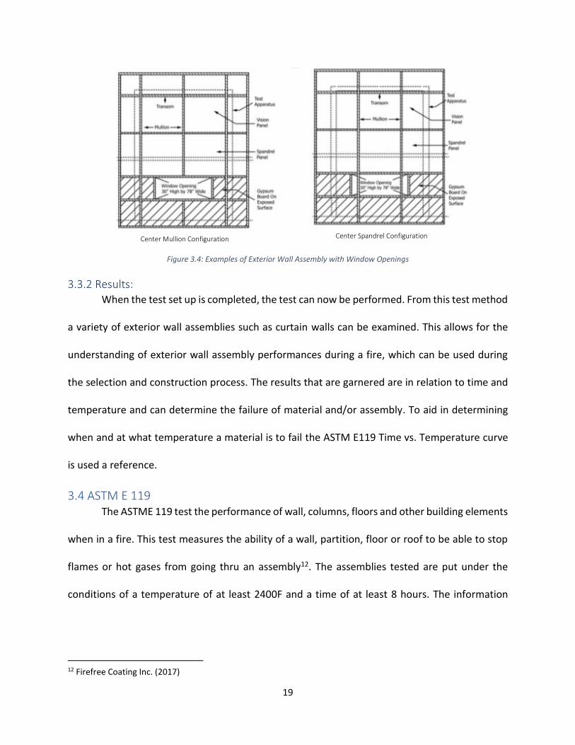
The exterior wall assembly used during these test is determined by the test sponsor and
laboratory and should be secured to the testing apparatus. The minimum height and width of the
exterior wall assembly should be 17.5 by 13.33 ft. For the floor assembly of this structure it should
have a width of at least 12 in and have a length of 13ft. The window placed in the exterior wall
assembly should have a height and width of 30 by 78 in. Figure 3.4 below shows examples of
exterior wall assemblies and their attachment to the test apparatus.
1. Window Burner 10. Window Burner Location During Test 2. Slot in Burner 11. Exterior Wall Assembly 3. Gas Supply Line 12. Test Apparatus 4. Perimeter Joint Protection 13. Floor Assembly5 5. Window 14. Floor of Observation Room 6. Test Room in Test Apparatus 15. Roof Slab 7. Observation Room in Test Apparatus 16. Floor of Test Room 8. Horizontal Centerline of Burner 17. Window Sill Height 9. Vertical Centerline of Burner
Plan View of Window Burner
Side Elevation View of Window Burner Location
19
Figure 3.4: Examples of Exterior Wall Assembly with Window Openings
3.3.2 Results: When the test set up is completed, the test can now be performed. From this test method
a variety of exterior wall assemblies such as curtain walls can be examined. This allows for the
understanding of exterior wall assembly performances during a fire, which can be used during
the selection and construction process. The results that are garnered are in relation to time and
temperature and can determine the failure of material and/or assembly. To aid in determining
when and at what temperature a material is to fail the ASTM E119 Time vs. Temperature curve
is used a reference.
3.4 ASTM E 119 The ASTME 119 test the performance of wall, columns, floors and other building elements
when in a fire. This test measures the ability of a wall, partition, floor or roof to be able to stop
flames or hot gases from going thru an assembly12. The assemblies tested are put under the
conditions of a temperature of at least 2400F and a time of at least 8 hours. The information
12 Firefree Coating Inc. (2017)
Center Mullion Configuration Center Spandrel Configuration
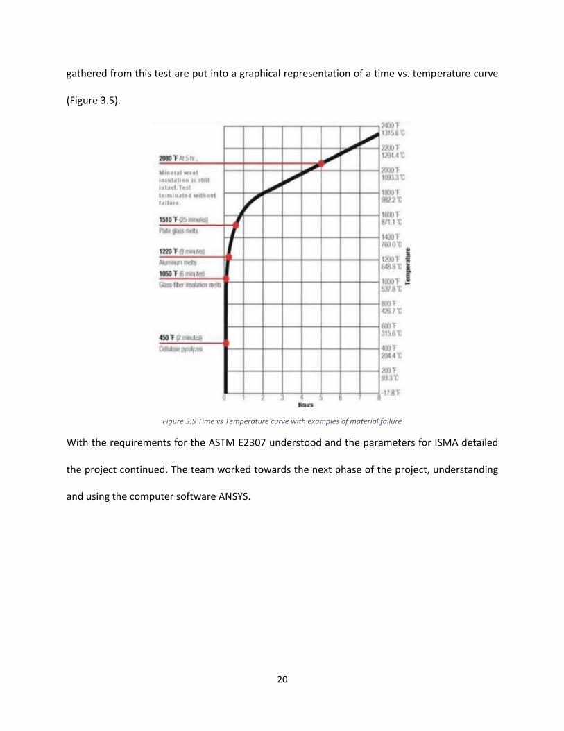
20
gathered from this test are put into a graphical representation of a time vs. temperature curve
(Figure 3.5).
Figure 3.5 Time vs Temperature curve with examples of material failure
With the requirements for the ASTM E2307 understood and the parameters for ISMA detailed
the project continued. The team worked towards the next phase of the project, understanding
and using the computer software ANSYS.
21
4. Methodology The goal of this project was to develop computerized simulation of the ASTME 2307: Fire
Resistance Test. Using the computer software ANSYS, the Intermediate Scale Multistory
Apparatus, used to test the Fire Resistance of a curtain wall was modeled. It gave a visual
representation of how the curtain wall selected for this project is effected when simulating the
fire of ASTME 2307 test. For instance, specific material will have varying strength, which will in
turn effect the thermal and structural performance of that material. For this project, the
deflection of materials, specifically the mullion was analyzed.
4.1 ANSYS To understand the structural and thermal performance of a curtain wall the computer
software ANSYS was used. ANSYS is a general-purpose software, used to simulate interaction of
all disciplines of physics, structural, vibration, fluid dynamics, heat transfer and electromagnetic
for engineers13. In this project, ANSYS was used to simulate the thermal and structural
performance of a curtain wall system when under the condition of the ASTME 2307 test. Simple
problems were used to first understand how the software dealt with different structural and
thermal conditions.
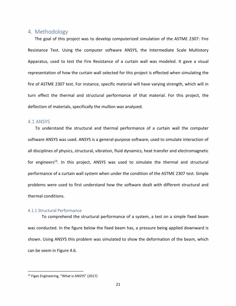
4.1.1 Structural Performance
To comprehend the structural performance of a system, a test on a simple fixed beam
was conducted. In the figure below the fixed beam has, a pressure being applied downward is
shown. Using ANSYS this problem was simulated to show the deformation of the beam, which
can be seem in Figure 4.6.
13 Figes Engineering, “What is ANSYS” (2017)
22
Figure 4.1: Fixed Beam
Figure 4.2: Deformation of the Fixed Beam
This theory of deformation when loading is applied can be used in a curtain wall system. The
loads being applied to the system are wind loads (applied longitudinally) and gravity loads
(applied latitudinal downward). These loads will cause a slight deformation to the curtain wall.
This structural performance was examined further in the test of the HLTI curtain wall system.
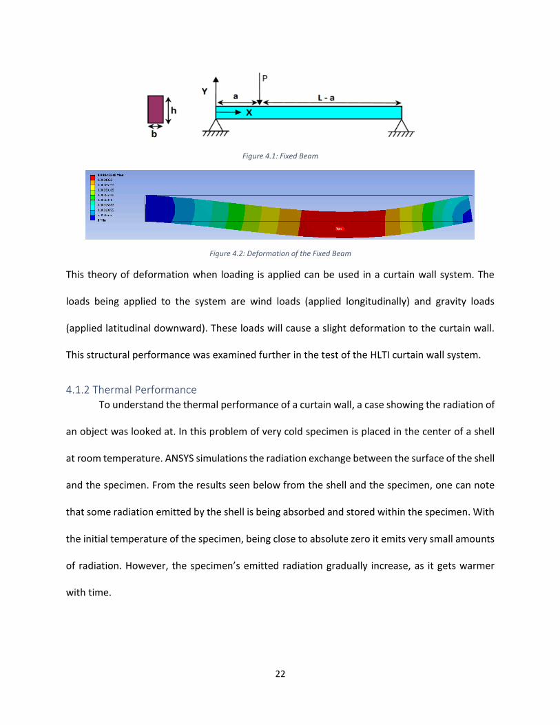
4.1.2 Thermal Performance To understand the thermal performance of a curtain wall, a case showing the radiation of
an object was looked at. In this problem of very cold specimen is placed in the center of a shell
at room temperature. ANSYS simulations the radiation exchange between the surface of the shell
and the specimen. From the results seen below from the shell and the specimen, one can note
that some radiation emitted by the shell is being absorbed and stored within the specimen. With
the initial temperature of the specimen, being close to absolute zero it emits very small amounts
of radiation. However, the specimen’s emitted radiation gradually increase, as it gets warmer
with time.

23
This type of thermal reaction can be used when looking at a fire within a curtain wall
system. For instance, the glass will absorb the heat being emitted from the fire. As the fire grows
hotter over time, the glass will absorb more of the heat which can then cause a reaction within
the glass, the glass can fail and combust. This theory is looked into further in the model of the
HILTI curtain wall system.
Figure 4.4: Thermal Reading of Specimen
4.1.3 Combination of Structural and Thermal Performance Examining the structural and thermal performance together of a building can allow for
understanding of how these properties work together. In the example below there is a simply
fixed beam place between two walls and the temperature on the bar with an initial temperature
of 22C and is increased to 100C. With the increase in temperature on the beam will cause a
deformation of the beam, either expanding or contracting.
Figure 4.3: Thermal Reading of Shell

24
Figure 4.5: Simply fixed beam between two walls
Figure 4.6: Thermal Result - temperature remains at 122C
Figure 4.7: Structural Result - total deformation of beam is 0.002m
The results of the jointed thermal and structural analysis of beam can be seen above in figures
4.6 and 4.7. The thermal results show that with the beam in steady state that the beam has a
constant temperature of 122C, going from initial temperature of 22C increasing 100C to have a
final temperature of 122C. With the temperature increasing, the material of the beam is affected.
In this example, the beam experiences a stretch, causing an elastic change in the beam, increasing
0.002m.
25
Comparing this model to the curtain wall system looked at, the temperature increase
from the fire will cause the material such as, the glass and mullion system to deform. Also, the
loads being applied to the to the system simultaneously with temperature change will result in
addition deformation of the system because wind loads, gravity loads, and self-weight of the
system are being applied.
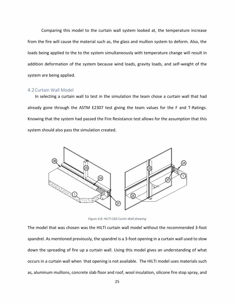
4.2 Curtain Wall Model In selecting a curtain wall to test in the simulation the team chose a curtain wall that had
already gone through the ASTM E2307 test giving the team values for the F and T-Ratings.
Knowing that the system had passed the Fire Resistance test allows for the assumption that this
system should also pass the simulation created.
Figure 4.8: HILTI CAD Curtin Wall drawing
The model that was chosen was the HILTI curtain wall model without the recommended 3-foot
spandrel. As mentioned previously, the spandrel is a 3-foot opening in a curtain wall used to slow
down the spreading of fire up a curtain wall. Using this model gives an understanding of what
occurs in a curtain wall when that opening is not available. The HILTI model uses materials such
as, aluminum mullions, concrete slab floor and roof, wool insulation, silicone fire stop spray, and

26
glass paneling. To fully understand this system, it is modeled in Auto CAD and then in ANSYS,
defining each element of the system including connections and parts of the curtain wall not seen
in the 3D CAD image provided by HILIT (figure 4.8). This model can then be examined through
the conditions required for thermal and structural analysis, which will be discussed further in the
methodology section of this report.
To perform the Fire Resistance Test, the curtain wall system had to follow the
requirements for the ISMA detailed in the ASTM E2307. The height of the curtain wall system had
to be at least 17-feet with a width of 13.33-feet. The floor slap had to have a thickness of at most
8 inches. Also, the simulated fire had to be a certain size and be raised a certain amount off the
ground. The fire had to be at least 30 inches in height and 78 inches in width because of the
window size. The exact height of the fire was not specified in the test and as a result, some
assumptions were made to garner the best outcome. Nevertheless, following these criteria
allowed for a more precise result in ANSYS.
Figure 4.9: 2D ANSYS of Glass Curtain in ISMA
Figure 4.10: 3D ANSYS pf Glass Curtain Wall in ISMA

27
4.2.1 2D Auto CAD The Auto CAD drawing of the non-spandrel curtain wall was the first step in being able to
design this virtual simulation of the Fire Resistance Test. This drawing details elements of the
curtain wall system not readily seen in figure 4.8. Using the CAD drawings provided by HILTI gave
a general idea of the elements that make up the curtain wall. The model was expanded upon to
meet the stipulations given by the ASTM E2307. A 2D elevation of the curtain wall was created in
Auto CAD and this elevation aided in conductimg the joint thermal and structural analysis of a
curtain wall.
Figure 4:11 2D Auto CAD of Glass Curtain Wall
The 2D Auto CAD model seen in figure 4.11 has the fire placed at the proper distance
away from the glass/mullion, 2 feet and the specified height above the floor, 2.5 feet, as the
window that holds the burners for the fire was 2.5 feet above the ground. For the simulation, the
28
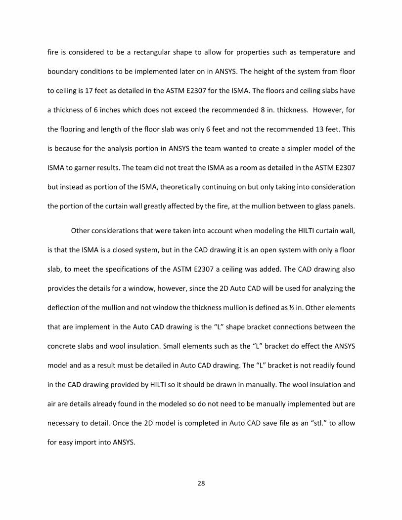
fire is considered to be a rectangular shape to allow for properties such as temperature and
boundary conditions to be implemented later on in ANSYS. The height of the system from floor
to ceiling is 17 feet as detailed in the ASTM E2307 for the ISMA. The floors and ceiling slabs have
a thickness of 6 inches which does not exceed the recommended 8 in. thickness. However, for
the flooring and length of the floor slab was only 6 feet and not the recommended 13 feet. This
is because for the analysis portion in ANSYS the team wanted to create a simpler model of the
ISMA to garner results. The team did not treat the ISMA as a room as detailed in the ASTM E2307
but instead as portion of the ISMA, theoretically continuing on but only taking into consideration
the portion of the curtain wall greatly affected by the fire, at the mullion between to glass panels.
Other considerations that were taken into account when modeling the HILTI curtain wall,
is that the ISMA is a closed system, but in the CAD drawing it is an open system with only a floor
slab, to meet the specifications of the ASTM E2307 a ceiling was added. The CAD drawing also
provides the details for a window, however, since the 2D Auto CAD will be used for analyzing the
deflection of the mullion and not window the thickness mullion is defined as ½ in. Other elements
that are implement in the Auto CAD drawing is the “L” shape bracket connections between the
concrete slabs and wool insulation. Small elements such as the “L” bracket do effect the ANSYS
model and as a result must be detailed in Auto CAD drawing. The “L” bracket is not readily found
in the CAD drawing provided by HILTI so it should be drawn in manually. The wool insulation and
air are details already found in the modeled so do not need to be manually implemented but are
necessary to detail. Once the 2D model is completed in Auto CAD save file as an “stl.” to allow
for easy import into ANSYS.
29
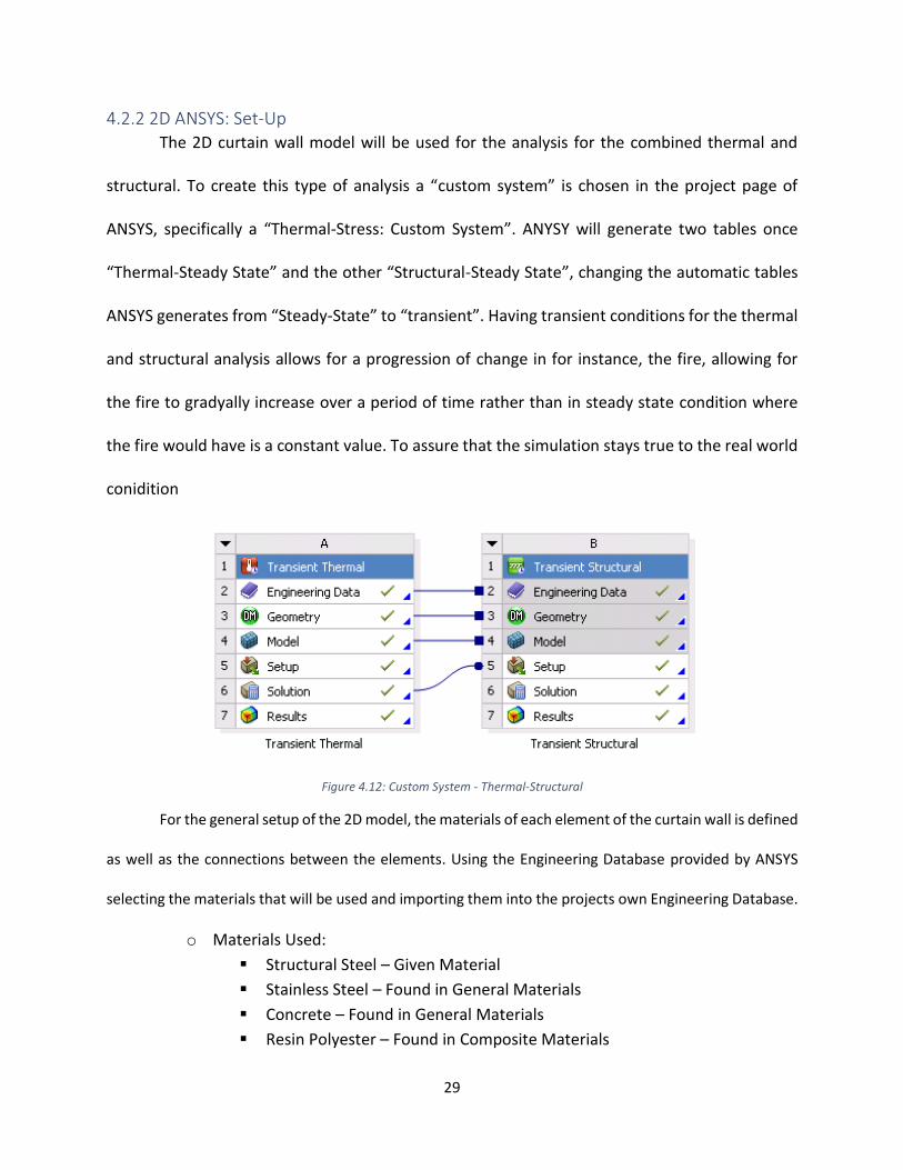
4.2.2 2D ANSYS: Set-Up The 2D curtain wall model will be used for the analysis for the combined thermal and
structural. To create this type of analysis a “custom system” is chosen in the project page of
ANSYS, specifically a “Thermal-Stress: Custom System”. ANYSY will generate two tables once
“Thermal-Steady State” and the other “Structural-Steady State”, changing the automatic tables
ANSYS generates from “Steady-State” to “transient”. Having transient conditions for the thermal
and structural analysis allows for a progression of change in for instance, the fire, allowing for
the fire to gradyally increase over a period of time rather than in steady state condition where
the fire would have is a constant value. To assure that the simulation stays true to the real world
conidition
Figure 4.12: Custom System - Thermal-Structural
For the general setup of the 2D model, the materials of each element of the curtain wall is defined
as well as the connections between the elements. Using the Engineering Database provided by ANSYS
selecting the materials that will be used and importing them into the projects own Engineering Database.
o Materials Used:
Structural Steel – Given Material
Stainless Steel – Found in General Materials
Concrete – Found in General Materials
Resin Polyester – Found in Composite Materials

30
Silicone Anisotropic – Found in General Materials
With the materials defined the 2D AutoCAD can be imported into the ANSYS geometry. In the
geometry portion of ANSYS the materials for each element was applied, the table below has the
elements of the curtain wall, the material, and the properties of the material which includes
density, isotropic conductivity, and specific heat.
Table 4.1: 2D Geometry Materials and their Thermal Properties
Elements of Curtain Wall Material Density
(kg.m-3)
Isotropic Conductivity
(W.m-1.C-1)
Specific Heat
(J.kg-1.C-1)
Mullion Stainless Steel 7750 15.1 480
Floor Slab Concrete 2300 0.72 780
Ceiling Slab
Firestop Spray Silicon 2330 148 712
Sheet Metal Pans Structural Steel 7850 60.5 434
In-Concrete Steel Angles
Curtain Wall Insulation Resin Polyester 1044 0.033 1500
When the geometry and materials are defined the ANSYS modeling of the curtain wall is
to follow. In the modeling portion of ANSYS connections between elements of the curtain wall
are specified. For the 2D model only bonded connections are considered. Bonded elements act
between contacting faces of structurally supporting bodies, as a result, there is no movement
between the elements. The table below shows the contacts that are made in ANYS. A more
detailed explanation of the general 2D ANSYS setup can be found in the Appendix: User’s guide.
31
Table 4.2: 2D Geometry Connection between Elements
Bonded
Sheet Metal Pan
In-Concrete Steel Angle
Mullion
Wool Insulation
Silicone Firestop Spray
Concrete
Wool Insulation
In-Concrete Steel Angle
Silicone Firestop Spray
Wool Insulation Silicone Firestop Spray
In-Concrete Steel Angle
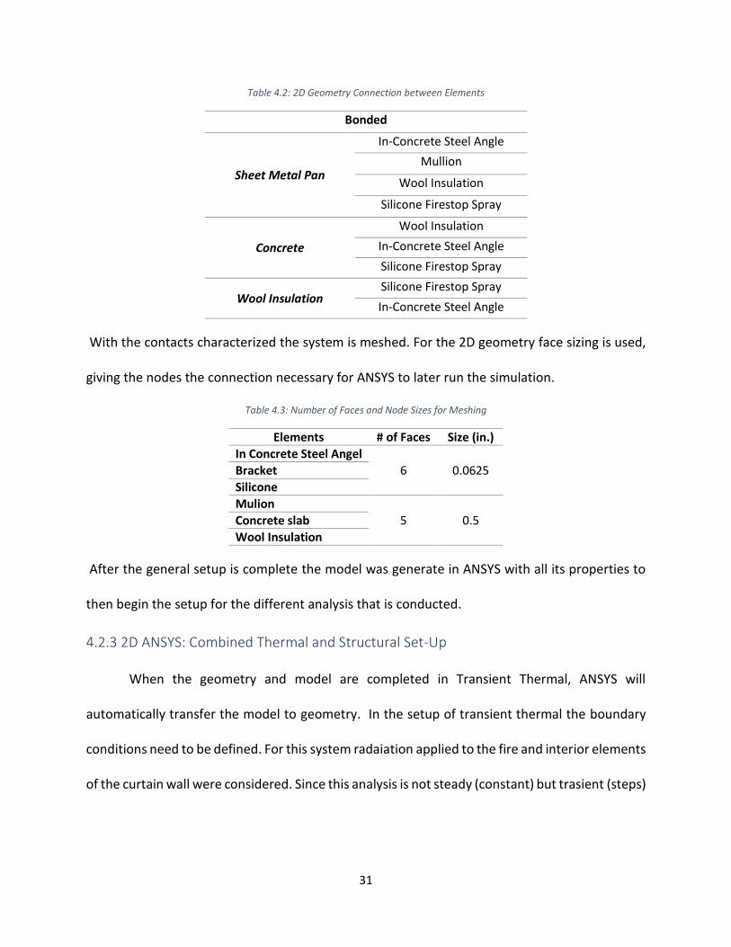
With the contacts characterized the system is meshed. For the 2D geometry face sizing is used,
giving the nodes the connection necessary for ANSYS to later run the simulation.
Table 4.3: Number of Faces and Node Sizes for Meshing
Elements # of Faces Size (in.)
In Concrete Steel Angel
6 0.0625 Bracket
Silicone
Mulion
5 0.5 Concrete slab
Wool Insulation
After the general setup is complete the model was generate in ANSYS with all its properties to
then begin the setup for the different analysis that is conducted.
4.2.3 2D ANSYS: Combined Thermal and Structural Set-Up
When the geometry and model are completed in Transient Thermal, ANSYS will
automatically transfer the model to geometry. In the setup of transient thermal the boundary
conditions need to be defined. For this system radaiation applied to the fire and interior elements
of the curtain wall were considered. Since this analysis is not steady (constant) but trasient (steps)

32
the data for radiation is in tablular data form, broken into 6 steps going from an initial time of 0s
to a final time of 7200s. The properties of the boundary conditions are as followed:
Table 4.4: 2D Radiation – Tabular Data
Element Boundary Emissivity Ambient Temperature (F)
Fire (Rectangle) Radiation 0.8 71.6 F
Interior elements of Curtain Wall Radiation 0.8 71.6 F
Another condition applied to this system is the temperature of fire, similar to radiation it will
gradually increase over time. The temperature starts at 71.6 F, for an average room temperature
and ends 1800 F, the start of melting of the mullion system as defined in the ASTM E119 Time vs.
Temperature curve. The breakdown of the temperature for the fire can be found in the table
below.
Table 4. 5: Fire Temperature – Tabular Data
Steps Time (s)
Temperature (F)
1 1 71.6
2 120 450
3 360 1050
4 540 1220
5 1500 1510
6 7200 1800
Once the boundary conditions the solution type was chosen to run the simulation. In the thermal
setup, the solution necessary is the temperature. Run the simulation and the results for
temperature can be found in section 5.
For structural analysis setup, boundary conditions such as, gravity and wind pressure are
taken into consideration. Gravity load is defined in ANSYS as 386.09 in/s2 in the y-axis and it is

33
applied to the whole system. Pressure is also defined in this analysis however, not as a constant
but tabular data detailed in Table 4.6 below.
Table 4.6: Wind Pressure – Tabular Data
Also, to assure that the structural analysis is performed correctly the elements in the curtain wall is
defined as a fixed support, resulting in no movement of curtain wall. When the setup is completed the
solution for structural in determined, for this simulation total deflection is taken into consideration. After
the individual set up are completed and the solutions are finalized the simulation can be run giving results
of the total deflection of the mullion based on the pressure, wind load and fire temperature.
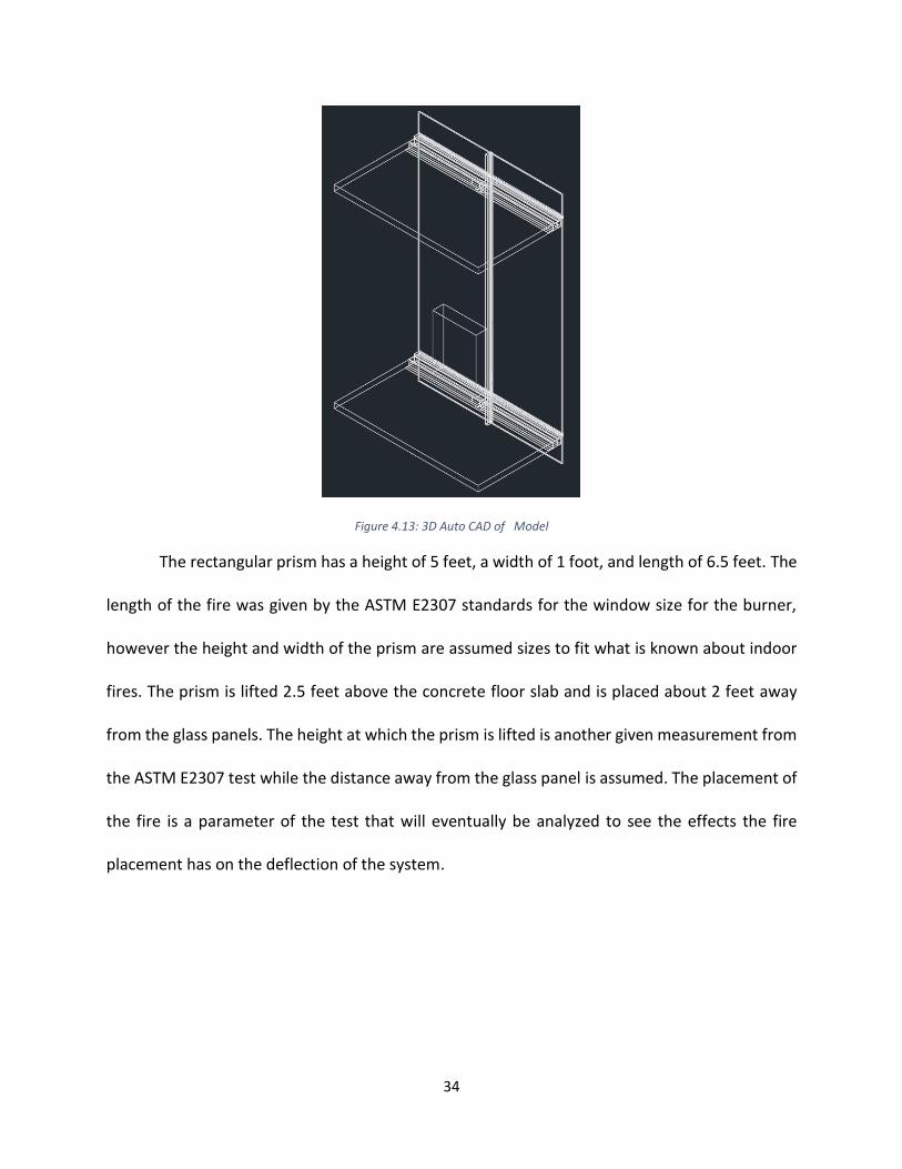
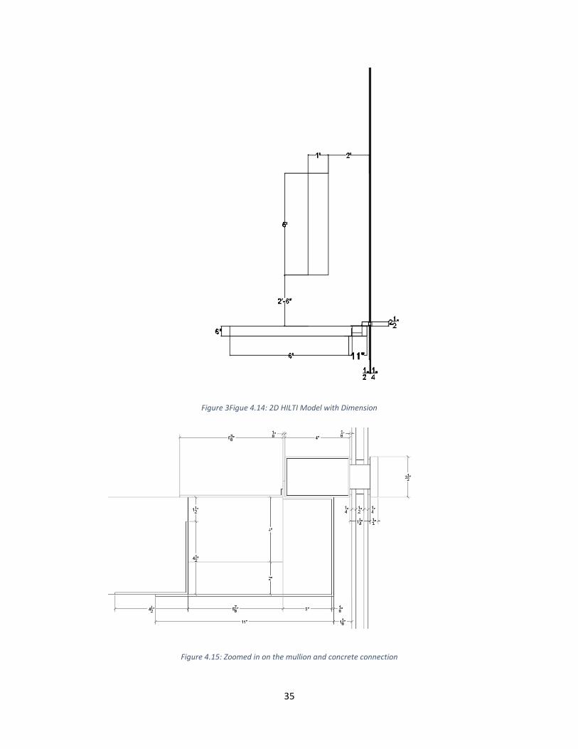
4.2.4 3D Auto CAD The 3D Auto CAD of the curtain wall is used for the individual analysis of the individual
thermal and structural performance of the system. The image below (figure 4.17) shows two-
pane glass panels that were elongated to the proper height for the ASTM E2307 test, 17 feet. It
was made to be a closed system like in the 2D Auto CAD, thus, there is concrete flooring and
concrete roof held in place by a two steel/aluminum mullions that create an “I” shape. Another
element that was placed in the CAD drawing is a rectangular prism again, it will act as heat
source/fire when performing the thermal and structural test in ANSYS.
Steps Time (s)
Pressure (Psi)
1 1 8.35
2 120 8.35
3 360 8.35
4 540 8.35
5 1500 8.35
34
Figure 4.13: 3D Auto CAD of Model
The rectangular prism has a height of 5 feet, a width of 1 foot, and length of 6.5 feet. The
length of the fire was given by the ASTM E2307 standards for the window size for the burner,
however the height and width of the prism are assumed sizes to fit what is known about indoor
fires. The prism is lifted 2.5 feet above the concrete floor slab and is placed about 2 feet away
from the glass panels. The height at which the prism is lifted is another given measurement from
the ASTM E2307 test while the distance away from the glass panel is assumed. The placement of
the fire is a parameter of the test that will eventually be analyzed to see the effects the fire
placement has on the deflection of the system.
35
Figure 3Figue 4.14: 2D HILTI Model with Dimension
Figure 4.15: Zoomed in on the mullion and concrete connection
36
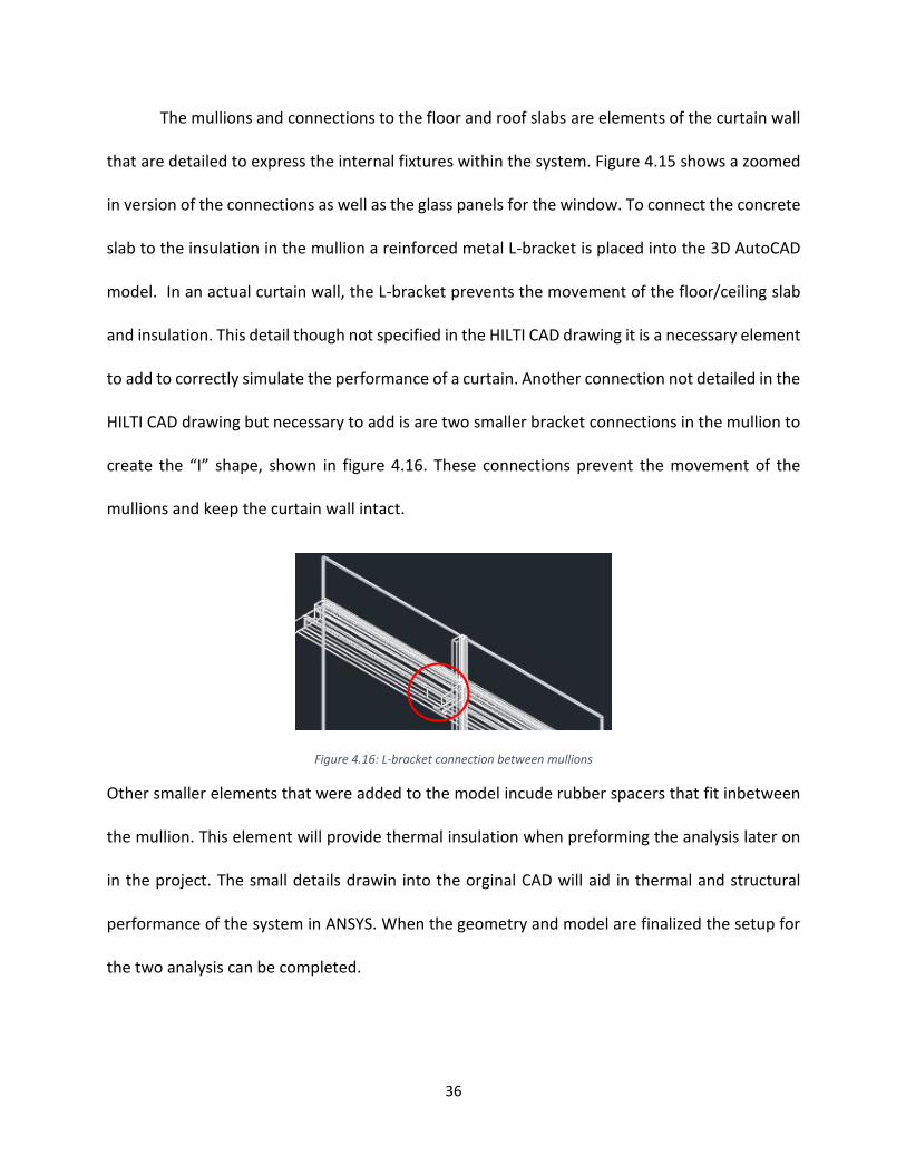
The mullions and connections to the floor and roof slabs are elements of the curtain wall
that are detailed to express the internal fixtures within the system. Figure 4.15 shows a zoomed
in version of the connections as well as the glass panels for the window. To connect the concrete
slab to the insulation in the mullion a reinforced metal L-bracket is placed into the 3D AutoCAD
model. In an actual curtain wall, the L-bracket prevents the movement of the floor/ceiling slab
and insulation. This detail though not specified in the HILTI CAD drawing it is a necessary element
to add to correctly simulate the performance of a curtain. Another connection not detailed in the
HILTI CAD drawing but necessary to add is are two smaller bracket connections in the mullion to
create the “I” shape, shown in figure 4.16. These connections prevent the movement of the
mullions and keep the curtain wall intact.
Figure 4.16: L-bracket connection between mullions
Other smaller elements that were added to the model incude rubber spacers that fit inbetween
the mullion. This element will provide thermal insulation when preforming the analysis later on
in the project. The small details drawin into the orginal CAD will aid in thermal and structural
performance of the system in ANSYS. When the geometry and model are finalized the setup for
the two analysis can be completed.
37
4.2.5 3D ANSYS: Set-Up To complete the thermal and structural analysis of the 3D model in ANSYS, consider the
general setup of the model, meaning having the correct curtain wall system imported into the
software and understanding what details need to be specified in the model for instance, the
material used and/or the connections between elements in the system. Once the geometry
solidified and the materials and connections are identified, the specialized set up for each type
of analysis can start.
38
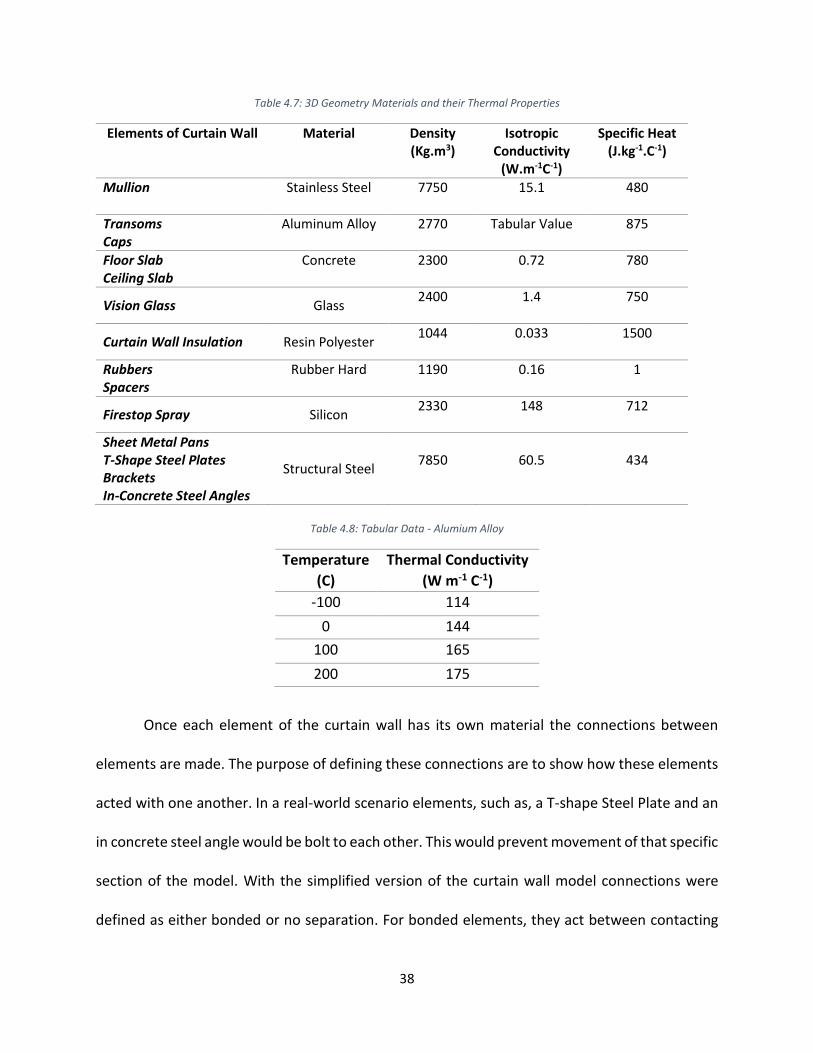
Table 4.7: 3D Geometry Materials and their Thermal Properties
Elements of Curtain Wall Material Density (Kg.m3)
Isotropic Conductivity
(W.m-1C-1)
Specific Heat (J.kg-1.C-1)
Mullion
Stainless Steel 7750 15.1 480
Transoms Caps
Aluminum Alloy 2770 Tabular Value
875
Floor Slab Ceiling Slab
Concrete 2300 0.72 780
Vision Glass Glass 2400 1.4 750
Curtain Wall Insulation Resin Polyester 1044 0.033 1500
Rubbers Spacers
Rubber Hard 1190 0.16 1
Firestop Spray Silicon 2330 148 712
Sheet Metal Pans T-Shape Steel Plates Brackets In-Concrete Steel Angles
Structural Steel 7850 60.5 434
Table 4.8: Tabular Data - Alumium Alloy
Temperature
(C)
Thermal Conductivity
(W m-1 C-1)
-100 114
0 144
100 165
200 175
Once each element of the curtain wall has its own material the connections between
elements are made. The purpose of defining these connections are to show how these elements
acted with one another. In a real-world scenario elements, such as, a T-shape Steel Plate and an
in concrete steel angle would be bolt to each other. This would prevent movement of that specific
section of the model. With the simplified version of the curtain wall model connections were
defined as either bonded or no separation. For bonded elements, they act between contacting
39
faces of structurally supporting bodies, as a result, there is no movement between the elements.
For no separate elements, they act between contracting face of thermal insulation bodies and
those of other bodies, these elements are connected but can move laterally (up and down).
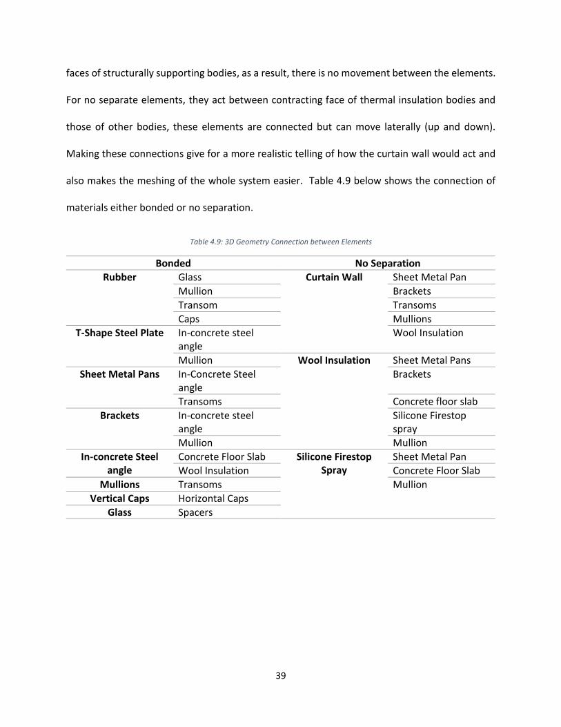
Making these connections give for a more realistic telling of how the curtain wall would act and
also makes the meshing of the whole system easier. Table 4.9 below shows the connection of
materials either bonded or no separation.
Table 4.9: 3D Geometry Connection between Elements
Bonded No Separation
Rubber Glass Curtain Wall Sheet Metal Pan
Mullion Brackets
Transom Transoms
Caps Mullions
T-Shape Steel Plate In-concrete steel angle
Wool Insulation
Mullion Wool Insulation Sheet Metal Pans
Sheet Metal Pans In-Concrete Steel angle
Brackets
Transoms Concrete floor slab
Brackets In-concrete steel angle
Silicone Firestop spray
Mullion Mullion
In-concrete Steel angle
Concrete Floor Slab Silicone Firestop Spray
Sheet Metal Pan
Wool Insulation Concrete Floor Slab
Mullions Transoms Mullion
Vertical Caps Horizontal Caps
Glass Spacers
40
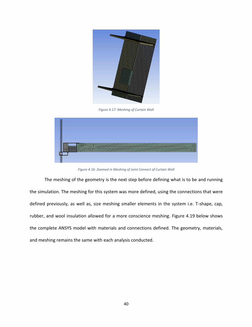
Figure 4.17: Meshing of Curtain Wall
Figure 4.16: Zoomed in Meshing of Joint Connect of Curtain Wall
The meshing of the geometry is the next step before defining what is to be and running
the simulation. The meshing for this system was more defined, using the connections that were
defined previously, as well as, size meshing smaller elements in the system i.e. T-shape, cap,
rubber, and wool insulation allowed for a more conscience meshing. Figure 4.19 below shows
the complete ANSYS model with materials and connections defined. The geometry, materials,
and meshing remains the same with each analysis conducted.

41
Figure 4.19: 3D Model of Curtain Wall
4.2.6 3D ANSYS: Thermal Set-Up Thought the general set up for ANSYS differ slightly from 2D to 3D the thermal set up
remains constant. To complete the thermal analysis, characterized the conditions for transient
heat transfer. For instance, stating the boundary conditions that will be using. For this system,
take into account radiation that would occur as a result of the fire, specifically use surface to
surface radiation that emits an emissivity of 0.8.
Table 4.10: Defined Boundaries in Surface to Surface Radiation
Surface to Surface Radiation
Fire Interior Surface
Inside glass Outside glass
Another condition that was defined was fire. Using the ASTM E 119 Time vs. Temperature curve
precise values to how the temperature changed over a time. Showing the steps of temperature
increase in a period of two hours, giving us an estimated temperature of the fire at every step.
The two-hour range is in direct correlation with the actual ASTM E 2307 and the UL listed table
provide with the curtain wall system. Over the two-hours aluminum is assumed to start melting

42
(9 minutes, temperature 1220 F). This condition is one that can be tested in the simulation to see
if the model is accurate.
4.2.7 3D ANSYS: Structural Set-Up For structural 3D analysis, the project type is defined as static structural ANSYS. Having a
static protect type results in specifications being constant and not changing over time. The set-
up for structural analysis take into consideration the boundary conditions, loading being applied
to the system both laterally and longitudinally, as well as wind pressure.
Table 4.11: 3D Geometry Structural Boundary Conditions and Properties
Geometry Boundary Value Applied by
11 faces Pressure 0.11 psi Surface Effect
All Bodies Gravity -386.09 in/s2 (z-direction)
Similar to the structural setup for 2D the type of supports need for the curtain wall was defined,
in this simulation, the floor and ceiling, as well as the glasses are fixed supports. Once the setup
is complete the solutions for the analysis are define. For this simulation the Total Deformation,
Equivalent Elastic Strain, and Equivalent Stress are take into consideration.
43
5. Results The results garnered from the simulation are split into three analysis, thermal, structural
and combination of thermal-structural. For the individual thermal analysis the effects of
temperature of fire was examined, as well as the heat flux in the curtain wall caused by the fire.
In the individual analysis of the structural aspect of the curtain wall the total deformation caused
by the loads being applied to the curtain wall. Additional information garnered from the
structural analysis is the equivalent stress and strain applied to the curtain wall. For the combined
Thermal-Structural analysis total deformation caused by loading and fire temperature over a
period of two hours. The results of each analysis is detailed further in the following few
paragraphs.
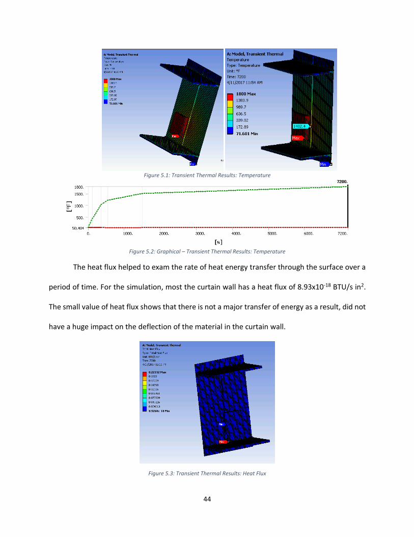
5.1 Thermal Results In the analysis of the thermal performance of the curtain the max heat sources is the fire
which increased from 0 seconds to 7200 seconds (hours) from an ambient temperature of 71.6 F
to a max temperature of 1800F. The heat is radiating out to elements such as, inside and outside
glass, and interior surfaces of the curtain wall. Checking the mullion of the curtain wall the applied
by the fire is about 1402 F. This shows that the element that gets most of the heat from the fire
is the mullion system. With the placement of the fire and its proximity to mullion that result
garnered from the test is true.
44
Figure 5.1: Transient Thermal Results: Temperature
Figure 5.2: Graphical – Transient Thermal Results: Temperature
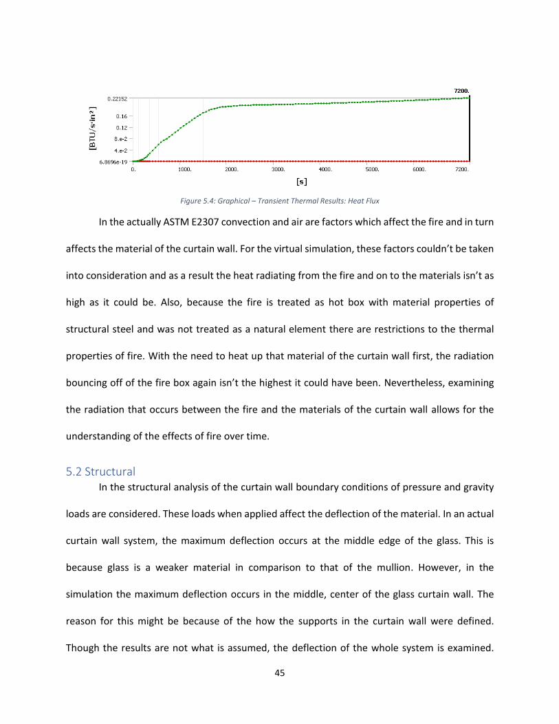
The heat flux helped to exam the rate of heat energy transfer through the surface over a
period of time. For the simulation, most the curtain wall has a heat flux of 8.93x10⁻¹⁸ BTU/s in2.
The small value of heat flux shows that there is not a major transfer of energy as a result, did not
have a huge impact on the deflection of the material in the curtain wall.
Figure 5.3: Transient Thermal Results: Heat Flux
45
Figure 5.4: Graphical – Transient Thermal Results: Heat Flux
In the actually ASTM E2307 convection and air are factors which affect the fire and in turn
affects the material of the curtain wall. For the virtual simulation, these factors couldn’t be taken
into consideration and as a result the heat radiating from the fire and on to the materials isn’t as
high as it could be. Also, because the fire is treated as hot box with material properties of
structural steel and was not treated as a natural element there are restrictions to the thermal
properties of fire. With the need to heat up that material of the curtain wall first, the radiation
bouncing off of the fire box again isn’t the highest it could have been. Nevertheless, examining
the radiation that occurs between the fire and the materials of the curtain wall allows for the
understanding of the effects of fire over time.
5.2 Structural In the structural analysis of the curtain wall boundary conditions of pressure and gravity
loads are considered. These loads when applied affect the deflection of the material. In an actual
curtain wall system, the maximum deflection occurs at the middle edge of the glass. This is
because glass is a weaker material in comparison to that of the mullion. However, in the
simulation the maximum deflection occurs in the middle, center of the glass curtain wall. The
reason for this might be because of the how the supports in the curtain wall were defined.
Though the results are not what is assumed, the deflection of the whole system is examined.

46
Using the parameter for the deflection of stainless steel “L/360” the assumption for the
deflection of the steel mullion is about 0.5 in. in the simulation, the deflection garnered for the
mullion was about 0.37908 in. which is less than the max deflection calculated. Showing that
though the maximum deflection is not where expected the simulation does exceed the max
deflection
Figure 5.5: Static Structural Results: Total Deformation
Another aspect of static structural that is looked at is the Equivalent Elastic Strain and
Equivalent Stress caused by the loading. Having these two results helped in understanding the
strength in material. The Equivalent Elastic Strain shows the strain in which the element under
loading and deformation returns to its original shape and size when the loading is removed. For
most of the curtain wall has the same value of Equivalent Stress Strain as shown in figure 5.6.
47
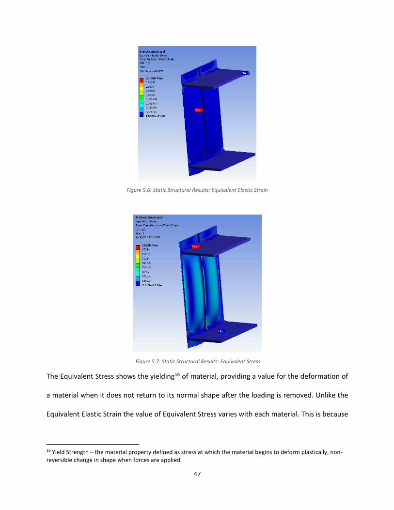
Figure 5.6: Static Structural Results: Equivalent Elastic Strain
Figure 5.7: Static Structural Results: Equivalent Stress
The Equivalent Stress shows the yielding16 of material, providing a value for the deformation of
a material when it does not return to its normal shape after the loading is removed. Unlike the
Equivalent Elastic Strain the value of Equivalent Stress varies with each material. This is because
16 Yield Strength – the material property defined as stress at which the material begins to deform plastically, non-reversible change in shape when forces are applied.

48
the strength in material is different for each. These additional tests though do not affect the total
deformation of the materials do provide background to how the materials are influenced by the
loading be applied.
5.3 Thermal & Structural The Thermal and Structural analysis took into consideration the temperature of fire and
the loading being applied to the curtain wall showing the deformation. For this analysis only the
deflection of the mullion was studied. The results of the simulation show that maximum
deflection of 0.28831 in. at the end of 1500s with a total max deflection of 0.351 in. at the end
of 540s. The deflection resulting from this analysis differs slightly from the deflection found in
the individual structural analysis. This might be because this simulation is taking into
consideration fire and wind pressure, with wind pressure in one direction and the fire in the other
the corresponding deflections cancel each other out giving a smaller value. The deflection shown
in figure 5.8 is not one that is expected. When a load is being applied to a mullion the deflection
usually bows out but the in the simulation the maximum deflection bows in toward the fire. This
result might have again been because of the whole system being a fixed support, in an actual
curtain wall there is slight movement between materials giving a different shape for deflection.
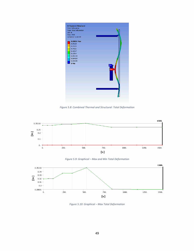
49
Figure 5.8: Combined Thermal and Structural: Total Deformation
Figure 5.9: Graphical – Max and Min Total Deformation
Figure 5.10: Graphical – Max Total Deformation
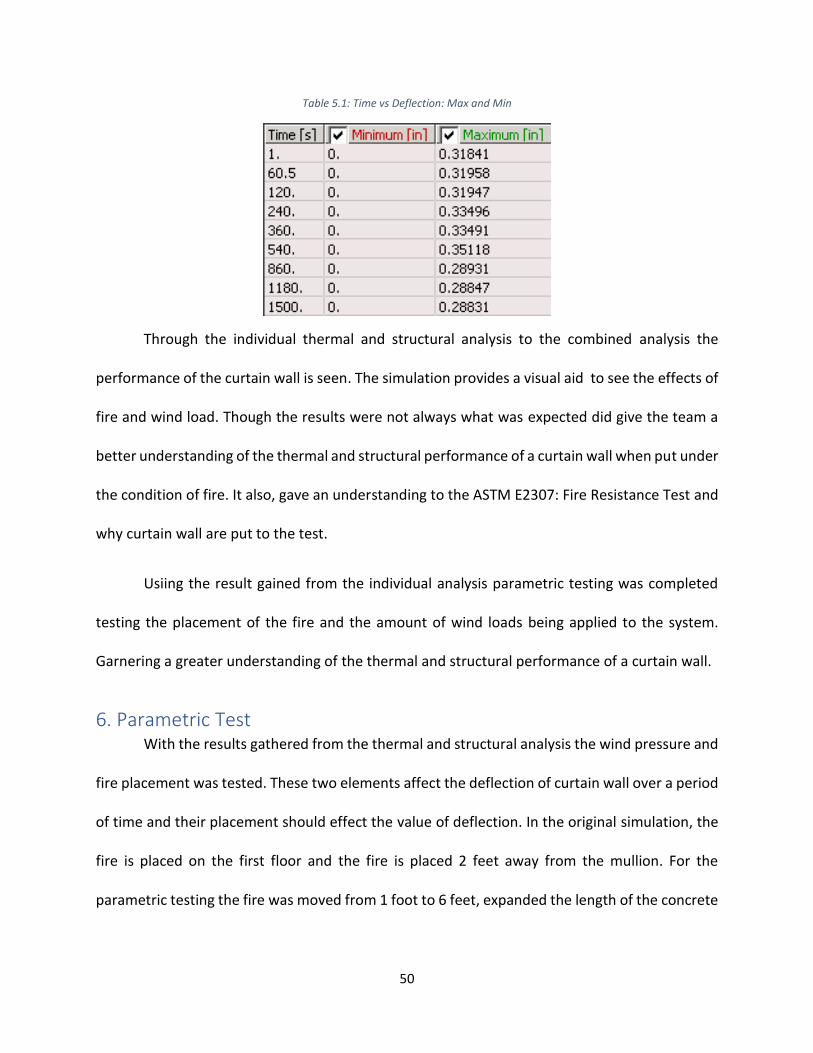
50
Table 5.1: Time vs Deflection: Max and Min
Through the individual thermal and structural analysis to the combined analysis the
performance of the curtain wall is seen. The simulation provides a visual aid to see the effects of
fire and wind load. Though the results were not always what was expected did give the team a
better understanding of the thermal and structural performance of a curtain wall when put under
the condition of fire. It also, gave an understanding to the ASTM E2307: Fire Resistance Test and
why curtain wall are put to the test.
Usiing the result gained from the individual analysis parametric testing was completed
testing the placement of the fire and the amount of wind loads being applied to the system.
Garnering a greater understanding of the thermal and structural performance of a curtain wall.
6. Parametric Test With the results gathered from the thermal and structural analysis the wind pressure and
fire placement was tested. These two elements affect the deflection of curtain wall over a period
of time and their placement should effect the value of deflection. In the original simulation, the
fire is placed on the first floor and the fire is placed 2 feet away from the mullion. For the
parametric testing the fire was moved from 1 foot to 6 feet, expanded the length of the concrete
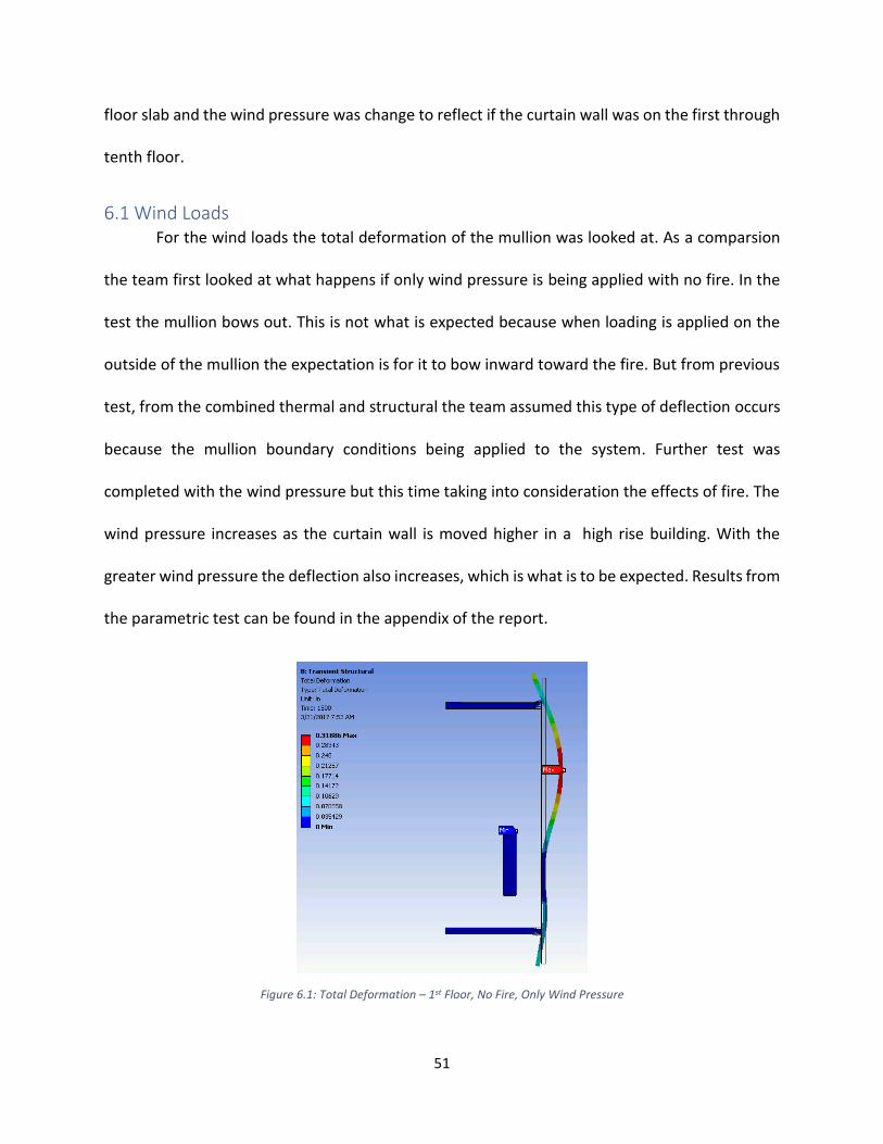
51
floor slab and the wind pressure was change to reflect if the curtain wall was on the first through
tenth floor.
6.1 Wind Loads For the wind loads the total deformation of the mullion was looked at. As a comparsion
the team first looked at what happens if only wind pressure is being applied with no fire. In the
test the mullion bows out. This is not what is expected because when loading is applied on the
outside of the mullion the expectation is for it to bow inward toward the fire. But from previous
test, from the combined thermal and structural the team assumed this type of deflection occurs
because the mullion boundary conditions being applied to the system. Further test was
completed with the wind pressure but this time taking into consideration the effects of fire. The
wind pressure increases as the curtain wall is moved higher in a high rise building. With the
greater wind pressure the deflection also increases, which is what is to be expected. Results from
the parametric test can be found in the appendix of the report.
Figure 6.1: Total Deformation – 1st Floor, No Fire, Only Wind Pressure
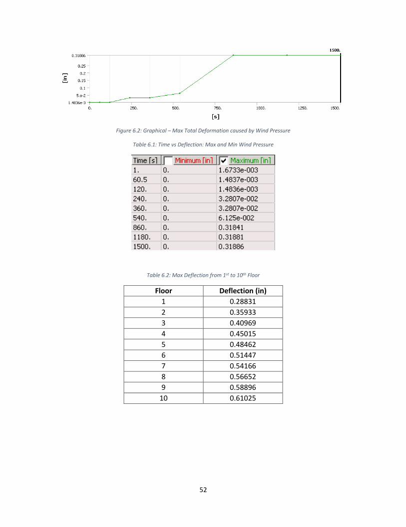
52
Figure 6.2: Graphical – Max Total Deformation caused by Wind Pressure
Table 6.1: Time vs Deflection: Max and Min Wind Pressure
Table 6.2: Max Deflection from 1st to 10th Floor
Floor Deflection (in)
1 0.28831
2 0.35933
3 0.40969
4 0.45015
5 0.48462
6 0.51447
7 0.54166
8 0.56652
9 0.58896
10 0.61025

53
6.2 Movement of Fire For the fire a similar approach was taken, the team took into account a curtain wall system
with noly fire and no wind as the bases of the parametic testing. In this situation the mullion
deflects inward toward the fire. The expectation for this mullion is the closer the fire gets to the
mullion the greater the deflection causing the mullion to expand due to the higher temperatires.
As a result, the mullion should bow out and not in. Similar to the structural analysis the deflection
garnered is not the expectation. The reasoning behind this again, might be the boundary
conditions that were applied to the system.
Further testing is completed taking into consideration both the fire and wind pressure.
The results from this parametric testing show that the further the fire gets from the curtain wall
the lower the deflection. This result is what is to be expected because the mullion will expand
less if the heat is further away from it. The complete results from the parametric testing of fire
can be found in appendix of this paper.
Figure 6.3: Total Deformation caused by Fire Temperature
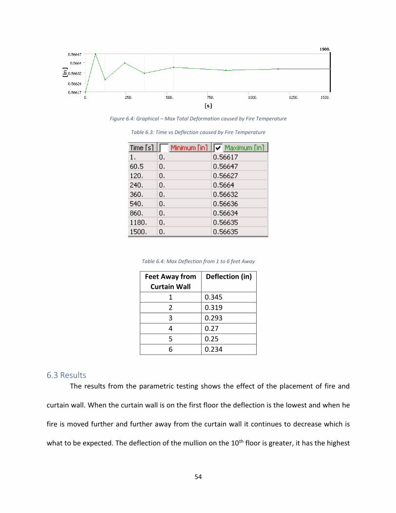
54
Figure 6.4: Graphical – Max Total Deformation caused by Fire Temperature
Table 6.3: Time vs Deflection caused by Fire Temperature
Table 6.4: Max Deflection from 1 to 6 feet Away
Feet Away from
Curtain Wall
Deflection (in)
1 0.345
2 0.319
3 0.293
4 0.27
5 0.25
6 0.234
6.3 Results The results from the parametric testing shows the effect of the placement of fire and
curtain wall. When the curtain wall is on the first floor the deflection is the lowest and when he
fire is moved further and further away from the curtain wall it continues to decrease which is
what to be expected. The deflection of the mullion on the 10th floor is greater, it has the highest

55
wind pressure but similar to the first floor the further the fire got from the curtain wall the
deflection decreases. Through the parametric testing the effect of the fire and wind pressure
could readily be seen.
Floor Wind Pressure (psi)
Deflection (in.)
1 ft. away 2 ft.
away
3 ft.
away
4 ft.
away
5 ft.
away
6 ft.
away
1st 8.35 0.371 0.351 0.339 0.330 0.324 0.322
2nd 10.18 0.441 0.423 0.411 0.403 0.397 0.395
3rd 11.43 0.490 0.473 0.461 0.454 0.448 0.445
4th 12.41 0.529 0.513 0.501 0.494 0.488 0.483
5th 13.23 0.562 0.546 0.535 0.527 0.522 0.517
6th 13.93 0.591 0.575 0.564 0.556 0.550 0.546
7th 14.56 0.616 0.601 0.590 0.582 0.577 0.572
8th 15.13 0.640 0.624 0.614 0.606 0.600 0.595
9th 15.64 0.661 0.646 0.635 0.627 0.621 0.617
10th 16.12 0.681 0.666 0.655 0.647 0.642 0.637
56
7. Conclusion All in all, the virtual simulation of the ASTM E2307: Fire Resistance Test detailed the
performance of the curtain wall. Through the thermal and structural analysis, the deflection
caused by the loading and fire temperature are visible. Though the results for the deflection are
not what was expected the general idea behind the fire resistance test, which is to see if the
curtain wall is structural and thermally sound for contstruction purposes can be garnered from
the results with gathered. From our individual thermal and structural and even the combined
analysis the deflection max for the mullion is not reached.
Through the parametric testing we saw that the curtain wall is able to handle the fire,
wind and gravity loads being applied to it from level 1 to 10. Beyond that point the deflection of
the mullion exceeds is yield strength. Nevertheless, being able to simulate the fire resistance test
gave a better understanding to the effects of fire and the importantace of the thermal and
structural strength of material. With fire being a major concern when constructing a building
attention has to be paid to every detailed and element being used.
7.1 Future Consideration If this project were to continue future teams should consider the following, continuing
with the parametric testing and analyszing a different type of curtain wall. In continuing with the
parametric testing the materials of the curtain wall could be changed. The materials used for this
simulation were readily available in the ANSYS database and might not meet requirements
thermal and structural requirements set forth by the building code. For instance, for the
simulation created float glass was used however, most curtain walls uses insulated glass. The
insulated glass could improve the thermal properties of the curtain wall changing the results

57
gained from the analysis. Making changes to the material properties to meet the proper thermal
requirements for a curtain wall could better simulate the actual results from the Fire Resistance
Test.
To get a better understanding of the effects of fire has on a curtain wall a comparison of
different curtain walls would be useful. Simulating a curtain wall with a 3-foot spandrel can show
the effects fire has on the opening provided by the spandrel. Being able to analyze the thermal
and structural performance of the system. All in all, continuing to gain knowledge about the
ASTM 2307 and being able to test the ffects of the ASTM E2307 can give more knowledge to the
fire performance of a curtain wall.

58

59
Appendix A: Data
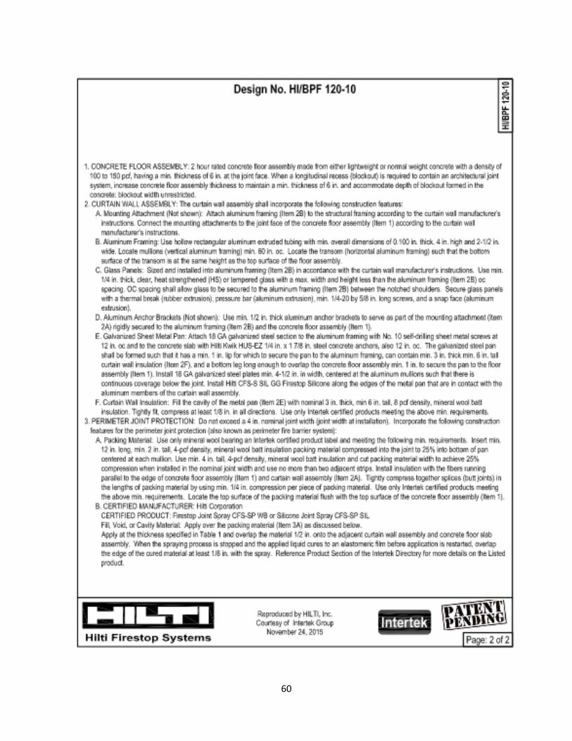
60
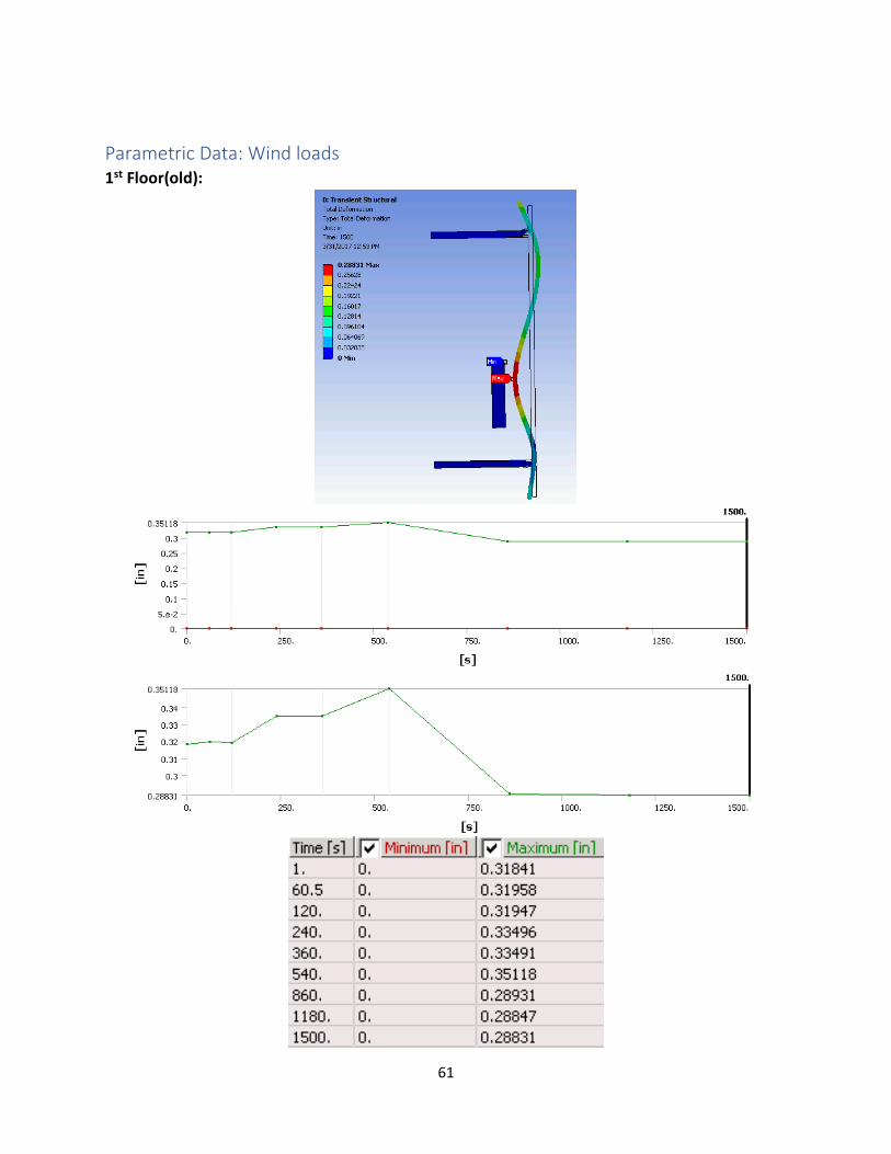
61
Parametric Data: Wind loads 1st Floor(old):
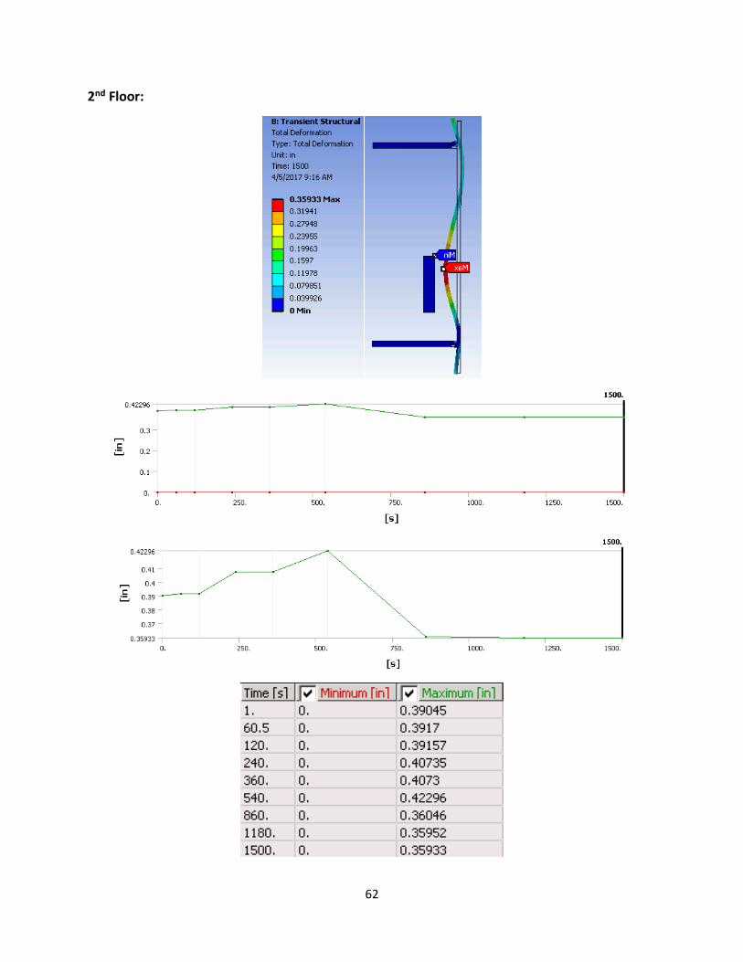
62
2nd Floor:
63
3rd Floor:

64
4th Floor:

65
5th Floor:

66
6th Floor:

67
7th Floor:
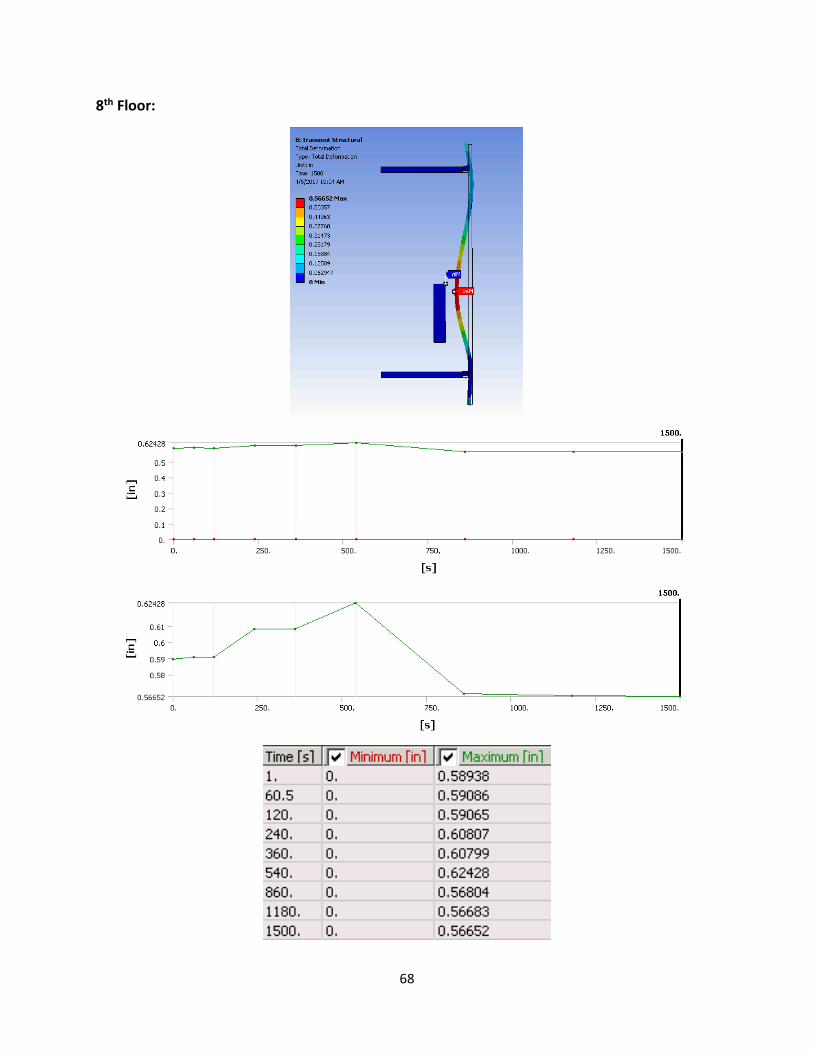
68
8th Floor:
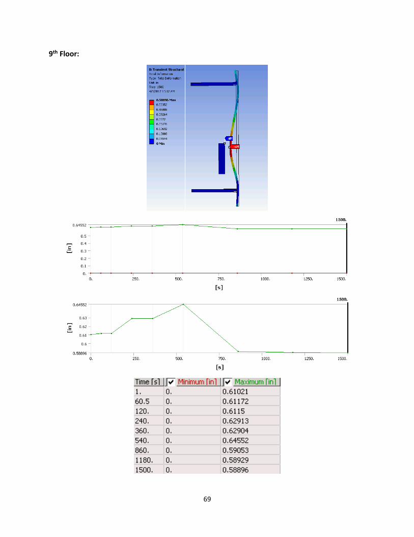
69
9th Floor:
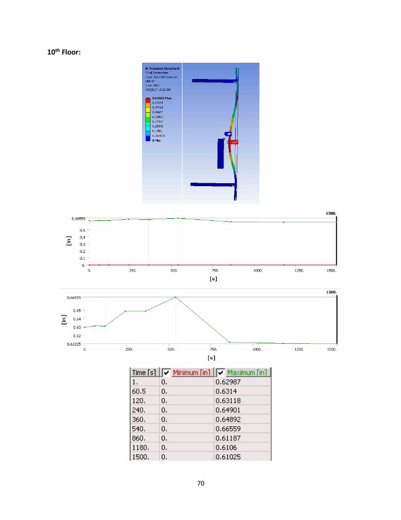
70
10th Floor:

71
Parametric Data: Fire Movement 0 Feet Away from Curtain Wall

72
1 Foot Away from Curtain Wall:

73
3 Feet Away from Curtain Wall
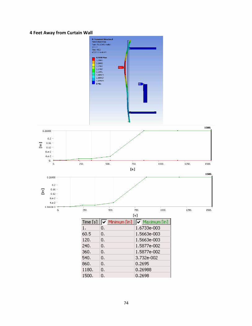
74
4 Feet Away from Curtain Wall

75
5 Feet Away from Curtain Wall
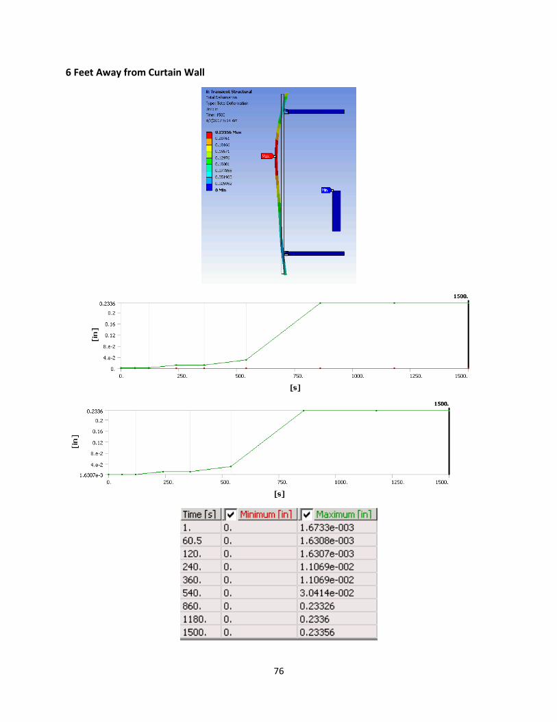
76
6 Feet Away from Curtain Wall

77
Appendix B: User’s Guide To create this simulation ANSYS 17.0 Workbench was used, other versions of ANSYS can be used
however, the button/command tabs might be different. Nevertheless, the same results should
be given if the following steps are followed.
First, open the ANSYS software tab on your computer. The image below is what you should see
when ANSYS finishes loading and opens.
Once open on the left-hand side “Toolbox” tab click the tab “Custom Systems” selecting
“Thermal-Stress”, the following two tables should appear on your project page. You then want
to change the tables property from “Steady-State” to “Transient”. To do this you right-click the
tab “Steady-State Thermal” or the “Steady State Structural” highlighted in blue, in the image
below. A list of options will be given to you and you want to select the option “Replace with” and
select the “transient”. You do the same procedure with the table that was not chosen.

78
When those changes are made, you will then go down the list of properties in the table making
the necessary alterations to each. Double click the “Engineering Data” tab, in this section you will
be choosing the materials that will be used for your model.
All materials used for curtain wall system can be found in the Engineering database of ANYS. To
gather those materials, click the tab “Engineering Data Sources” and choose the necessary
materials. For instance, when the “Engineering Data Source” is open click on “General Material”
tab which will then open a table of all materials filed under that category, scroll through and click
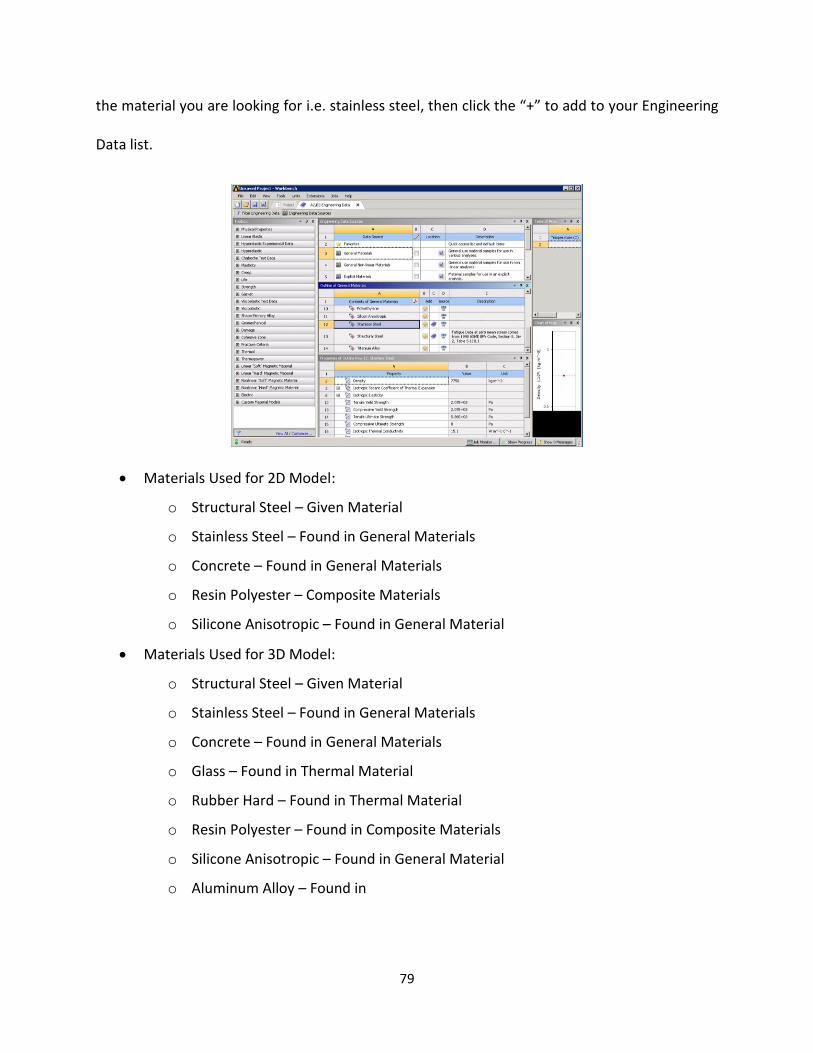
79
the material you are looking for i.e. stainless steel, then click the “+” to add to your Engineering
Data list.
Materials Used for 2D Model:
o Structural Steel – Given Material
o Stainless Steel – Found in General Materials
o Concrete – Found in General Materials
o Resin Polyester – Composite Materials
o Silicone Anisotropic – Found in General Material
Materials Used for 3D Model:
o Structural Steel – Given Material
o Stainless Steel – Found in General Materials
o Concrete – Found in General Materials
o Glass – Found in Thermal Material
o Rubber Hard – Found in Thermal Material
o Resin Polyester – Found in Composite Materials
o Silicone Anisotropic – Found in General Material
o Aluminum Alloy – Found in

80
For manually defined material you have to define the properties, for Aluminum
Alloy, Density, Isotropic Conductivity, and Specific Heat should be identified. To
do so you first have name the material in the “Contents of Engineering” table.
Once named the properties can be selected from the “Toolbox” tab on the left-
hand side. Density can be found in “physical properties”, while isotropic thermal
conductivity and enthalpy can be found in “thermal”.
o Defining Materials:
Density – 2770 kgm-3
Specific Heat – 875 Jkg-1K-1
Isotropic Thermal Conductivity – Tabular Data
Temperature
(C)
Thermal Conductivity
(W m-1 C-1)
-100 114
0 144
100 165
200 175
Materials Used for 2D Model:
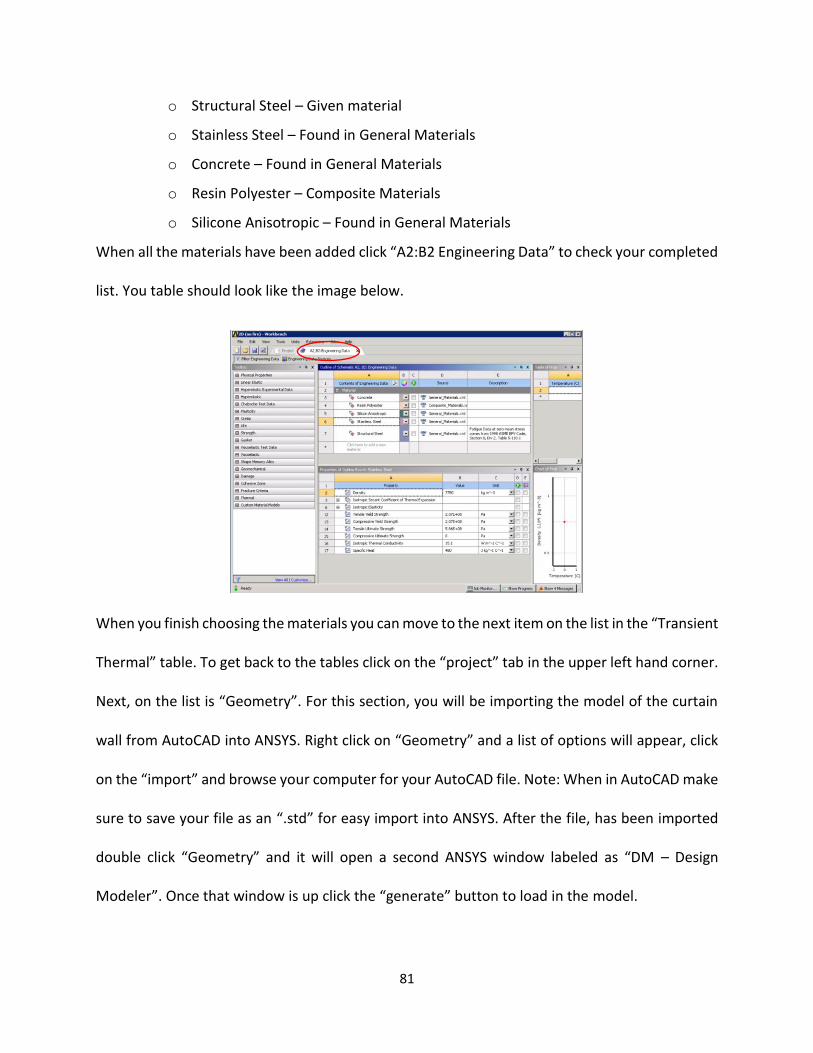
81
o Structural Steel – Given material
o Stainless Steel – Found in General Materials
o Concrete – Found in General Materials
o Resin Polyester – Composite Materials
o Silicone Anisotropic – Found in General Materials
When all the materials have been added click “A2:B2 Engineering Data” to check your completed
list. You table should look like the image below.
When you finish choosing the materials you can move to the next item on the list in the “Transient
Thermal” table. To get back to the tables click on the “project” tab in the upper left hand corner.
Next, on the list is “Geometry”. For this section, you will be importing the model of the curtain
wall from AutoCAD into ANSYS. Right click on “Geometry” and a list of options will appear, click
on the “import” and browse your computer for your AutoCAD file. Note: When in AutoCAD make
sure to save your file as an “.std” for easy import into ANSYS. After the file, has been imported
double click “Geometry” and it will open a second ANSYS window labeled as “DM – Design
Modeler”. Once that window is up click the “generate” button to load in the model.

82
Subsequently, when the geometry is loaded the edits to the model can then be made. Double
click “model” on the list under the transient thermal and it will load an additional window labeled
“M: Multiple System – Mechanical”. In this section, you will define the materials of each element
in the model, the connections between elements as well as, and meshing for better numeric
results when analyzing.
For geometry, you will first rename bodies and assign materials to corresponding bodies. In the
“outline” tab on the left-hand side you will click “Geometry” and it will open a list of parts in the
model. Right click on the individual parts and then click on the “Rename” tab. Once clicked the
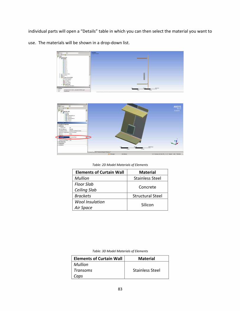
83
individual parts will open a “Details” table in which you can then select the material you want to
use. The materials will be shown in a drop-down list.
Table: 2D Model Materials of Elements
Elements of Curtain Wall Material
Mullion Stainless Steel
Floor Slab Ceiling Slab
Concrete
Brackets Structural Steel
Wool Insulation Air Space
Silicon
Table: 3D Model Materials of Elements
Elements of Curtain Wall Material
Mullion Transoms Caps
Stainless Steel
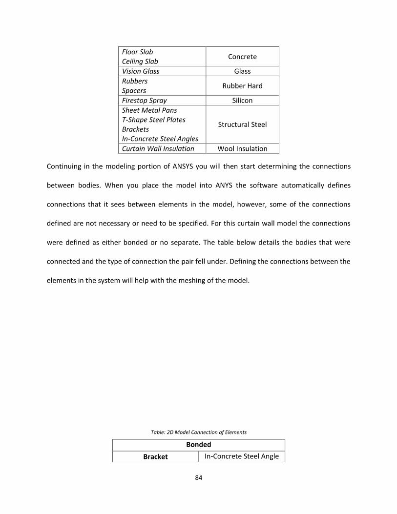
84
Floor Slab Ceiling Slab
Concrete
Vision Glass Glass
Rubbers Spacers
Rubber Hard
Firestop Spray Silicon
Sheet Metal Pans T-Shape Steel Plates Brackets In-Concrete Steel Angles
Structural Steel
Curtain Wall Insulation Wool Insulation
Continuing in the modeling portion of ANSYS you will then start determining the connections
between bodies. When you place the model into ANYS the software automatically defines
connections that it sees between elements in the model, however, some of the connections
defined are not necessary or need to be specified. For this curtain wall model the connections
were defined as either bonded or no separate. The table below details the bodies that were
connected and the type of connection the pair fell under. Defining the connections between the
elements in the system will help with the meshing of the model.
Table: 2D Model Connection of Elements
Bonded
Bracket In-Concrete Steel Angle

85
Mullion
In-Concrete Steel Angle
Wool Insulation
Concrete Floor Slab
Wool Insulation
Silicone Firestop Spray
Concrete Floor Slab
Mullion
Bracket
Silicone Firestop Spray Mullion
Concrete Floor Slab
Table: 3D Model Connection of Elements
Bonded No Separate
Rubber
Glass
Curtain Wall
Sheet Metal Pan
Mullion Brackets
Transom Transoms
Caps Mullions
T-Shape Steel Plate In-concrete steel angle
Wool Insulation
Mullion
Wool Insulation
Sheet Metal Pans
Sheet Metal Pans In-Concrete Steel angle
Brackets
Transoms Concrete floor slab
Brackets In-concrete steel angle
Silicone Firestop spray
Mullion Mullion
In-concrete Steel angle
Concrete Floor Slab
Silicone Firestop Spray
Sheet Metal Pan
Wool Insulation Concrete Floor Slab
Mullions Transoms Mullion
Vertical Caps Horizontal Caps
Glass Spacers
Keeping still in the Modeler window of ANYSY you will go down the list of commands in the
Outline table and click on “Meshing”. You will individually mesh some smaller components
defined in the 2D and 3D curtain wall.
The smaller elements that need to individually meshed for 2D are:
o In Concrete Steel Angle
o Bracket

86
o Silicone
The smaller elements that need to individually meshed for 3D are:
o Rubber
o T-Shape
o Wool Insulation
o Cap
To do this right click meshing and in the table provided select insert sizing. Choosing this
option will allow for ANSYS to create mesh that will fit the smaller elements. In indicating
sizing in ANSYS there is the option of either face or body. For example, for the 3D model for
Rubber and the T-shape select body, for wool insulation and cap select faces. In the body
option ANSYS selects the whole object needing to be meshed. In the face option, you
manually click each face of the object to receive proper meshing
For the 2D geometry select the option of face sizing for the meshing. In the table below are
the the elements and its defined sizing for the definition of element sizing in the meshing
table.

87
Table: 2D Mesh Type and Sizing
Elements # of Faces Size (in.)
In Concrete Steel Angel
6 0.0625 Bracket
Silicone
Mulion 5 0.5 Concrete slab
Wool Insulation
For the 3D geometery you will define elements as either being Face sizing or Body sizing. The
table below is what should be defined in the property table thar pops up for each element of the
curtain wall that is chosen to individually meshed.
Table: 3D Mesh Type and Sizing
Faces Bodies
Elements # of Faces Size (in.) Elements # of Bodies Size (in.)
Rubber 12 0.0625 Cap 6 0.0625
T-Shape 2 0.0625 Wool 4 0.5
Using the parameters listed above fill out the details table. Using the connections defined in the
tables of connections for either the 2D or 3D model generate a meshing for the curtain wall by
clicking “generate mesh” at the top of the page.
Zoomed in 2D meshing of geometry
3D meshing of geometry

88
The set-up for the analysis of the curtain wall depend on the type of test you want to conduct.
For the individual thermal and structural analysis use the 3D model. For the combination of
thermal and structural, as well as parametric testing the 2D model is used.
Structural Analysis:
For structural analysis assure that you use static structural when defining the project type in
ANSYS. Follow what is stated at the beginning of the user’s guide to assure that you select the
proper The Geometry and Model steps should follow those that are mentioned in the above
steps for the 3D model.
The set-up for structural analysis there are conditions that need to be defined in the model. You
want to take into consideration the boundary conditions for instance, the loading being applied
to the system both laterally and longitudinally, as well as fixed supports.
Geometry Boundary Value Applied by
11 faces Pressure 0.11 psi Surface Effect
All Bodies Gravity -386.09 in/s2 (z-direction)
`To apply these specific boundary conditions right click “Static Structural” in the outline
table. A drop-down list will appear and you will click “insert” and select the conditions
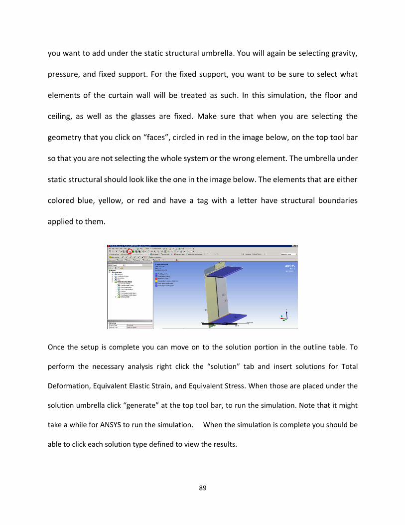
89
you want to add under the static structural umbrella. You will again be selecting gravity,
pressure, and fixed support. For the fixed support, you want to be sure to select what
elements of the curtain wall will be treated as such. In this simulation, the floor and
ceiling, as well as the glasses are fixed. Make sure that when you are selecting the
geometry that you click on “faces”, circled in red in the image below, on the top tool bar
so that you are not selecting the whole system or the wrong element. The umbrella under
static structural should look like the one in the image below. The elements that are either
colored blue, yellow, or red and have a tag with a letter have structural boundaries
applied to them.
Once the setup is complete you can move on to the solution portion in the outline table. To
perform the necessary analysis right click the “solution” tab and insert solutions for Total
Deformation, Equivalent Elastic Strain, and Equivalent Stress. When those are placed under the
solution umbrella click “generate” at the top tool bar, to run the simulation. Note that it might
take a while for ANSYS to run the simulation. When the simulation is complete you should be
able to click each solution type defined to view the results.

90
Result for Total Deformation in Static Structural
Results for Equivalent Elastic Strain
Results for Equivalent Stress
Thermal Analysis:
For Thermal Analysis assure that you choose “Transient Thermal” in your initial set of
ANSYS and you insert your 3D Auto CAD drawing for your geometry. Similar to structural analysis
the steps you will take for geometry and model will be the same and are mentioned in the initial
portion of the user’s guide.

91
The setup for Thermal Analysis there are conditions that need to be defined. The boundary
conditions for thermal analysis include: radiation of the fire, interior, outside and inside glass.
You also want to apply temperature to the fire. To insert these conditions you right click on
“Transient Thermal” and insert the four radiations and the temperature, renaming the conditions
to make it easier to distinguish. You will select each component of the curtain wall that you want
to apply the condition of radiation to separately make sure that the number of faces selected for
each component meets that of the table below.
Radiation # of Faces
Fire 6
Interior Glass 6
Exterior Glass 6
Interior 36
For radiation you want to manually define properties like ambient temperature and emissivity
once the geometry for fire, inside glass, outside glass, and interior are distinguished. For ambient
temperature and emissivity for inside glass, outside glass, and fire will be tabular data. To select
that option in ANSYS you will go to the details table of the chosen element and click on emissivity
an arrow will appear, click the arrow, and a drop down table will appear and select “tabular data”.
You will do the same for ambient temperature.

92
Once tabular data is click a table will appear and you will manual input the values. For inside
glass, outside glass, interior and fire the data below is what should be used.
Steps Time (s) Emissivity Ambient Temp (F)
1 1 0.8 71.6
2 120 0.8 71.6
3 360 0.8 71.6
4 540 0.8 71.6
5 1500 0.8 71.6
6 7200 0.8 71.6
For the temperature of fire you will select the “body” and not the faces of the rectangular prism.
Then you will define the details for temperature which again, will be tabular data increasing in
steps over a period of time.
Steps Time (s) Temperature (F)
1 1 71.6
2 120 450
3 360 1050
4 540 1220
5 1500 1510
6 7200 1800
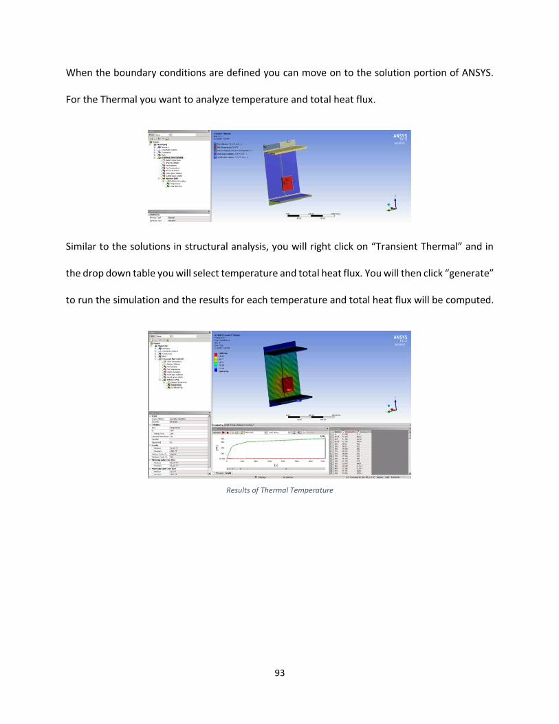
93
When the boundary conditions are defined you can move on to the solution portion of ANSYS.
For the Thermal you want to analyze temperature and total heat flux.
Similar to the solutions in structural analysis, you will right click on “Transient Thermal” and in
the drop down table you will select temperature and total heat flux. You will then click “generate”
to run the simulation and the results for each temperature and total heat flux will be computed.
Results of Thermal Temperature
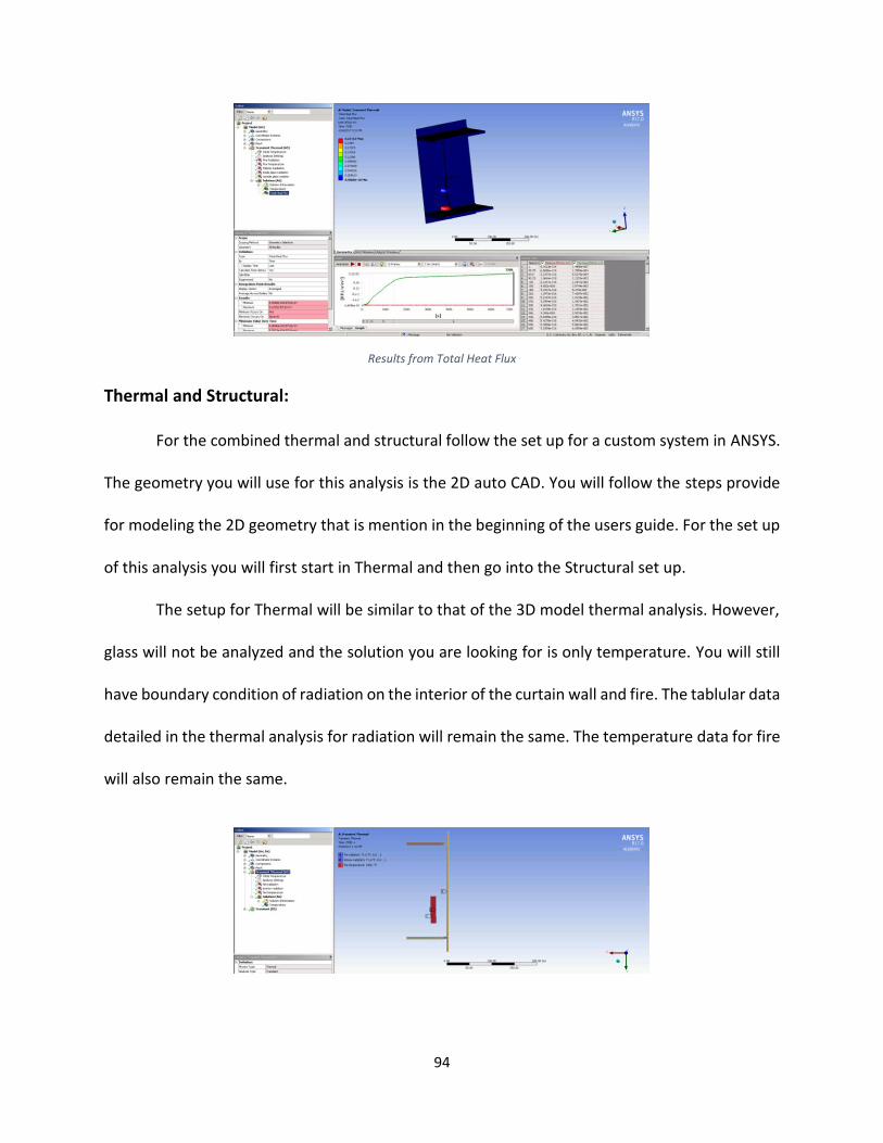
94
Results from Total Heat Flux
Thermal and Structural:
For the combined thermal and structural follow the set up for a custom system in ANSYS.
The geometry you will use for this analysis is the 2D auto CAD. You will follow the steps provide
for modeling the 2D geometry that is mention in the beginning of the users guide. For the set up
of this analysis you will first start in Thermal and then go into the Structural set up.
The setup for Thermal will be similar to that of the 3D model thermal analysis. However,
glass will not be analyzed and the solution you are looking for is only temperature. You will still
have boundary condition of radiation on the interior of the curtain wall and fire. The tablular data
detailed in the thermal analysis for radiation will remain the same. The temperature data for fire
will also remain the same.

95
For the solution again, you will follow the same steps only selecting “temperature” as a
solution. Click “generate” and run the simulation to get the results for thermal analysis.
For structural set up you will follow the same procedure defined in the 3D structural analysis. The
boundary conditions will be pressure, gravity loads, and the curtain wall will all be defined as
fixed support.
For the solution for structural analysis only total deformation will be taken into consideration.
Also because the thermal and structural are a combined analysis the temperature defined in the
thermal analysis will be automatically imported into the transient umbrella in the outline table.
You will click “generate” and ANSYS should run the simulation for both thermal and structural
giving you the deflection of the mullion as a result of the loading, wind pressure and the
temperature of the fire.
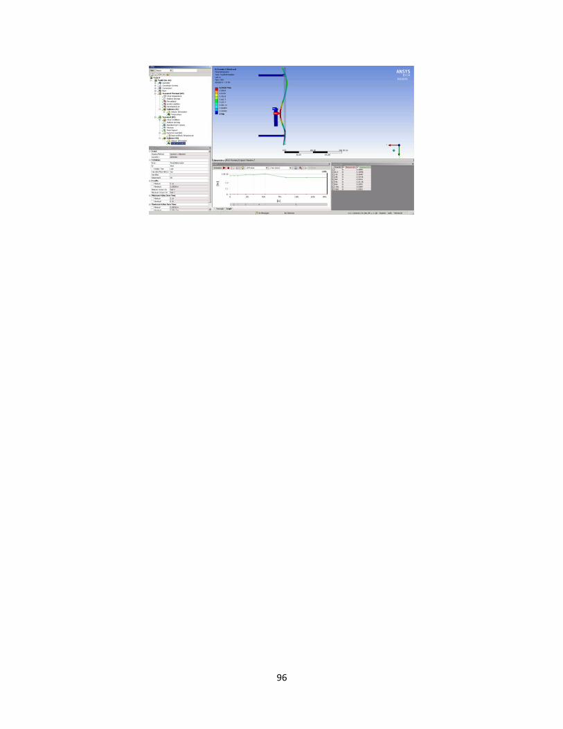
96
97
Work Cited
Arnold,Chris “Building Envelope Design Guide” Whole Building Design Guide (2016)
"ASTM E119 - 16a." ASTM International - Standards Worldwide. N.p., n.d. Web.
"ASTM E2307 - 15be1." ASTM International - Standards Worldwide. N.p., n.d. Web.
Fitch, William E., P.E. "Trends in Exterior Curtain Walls." SFPE Engineering a Fire Safe World.
Emerging Trends eNewletter,Web


![Quality Control of Glass Facades. component manufactu ... · Stick Curtain Wall System; (ii) Unitized Curtain Wall System [11]. In Portugal, the most applied method is the first one,](https://static.fdocuments.net/doc/165x107/5e6766f5230b93669659ffe1/quality-control-of-glass-facades-component-manufactu-stick-curtain-wall-system.jpg)