Fire Door Operator - Rolling Steel Doors
24
OWNER’S MANUAL MODEL FDC ADVANCED LOGIC INDUSTRIAL DUTY FIRE DOOR OPERATOR US PATENT NO. 6,014,307 LMPLC CONTROL CONTROL WIRED LMPLC NOT FOR RESIDENTIAL USE LISTED DOOR OPERATOR 41B6 Serial # (located on electrical box cover) Installation Date Wiring Type 2 YEAR WARRANTY
Transcript of Fire Door Operator - Rolling Steel Doors

OWNER’S MANUALMODEL FDC
ADVANCED LOGICINDUSTRIAL DUTY FIRE DOOR OPERATOR
US PATENT NO. 6,014,307
LMPLC CONTROL
C O N T R O L W I R E D
LMPLC
NOT FOR RESIDENTIAL USE
LISTED DOOR OPERATOR
41B6Serial #
(located on electrical box cover)
Installation Date
Wiring Type
2 YEAR WARRANTY
c 2002, The Chamberlain Group, Inc.
All rights ReservedLISTED DOOR OPERATOR
41B6
01-16219H
HOW TO ORDER REPAIR PARTS
INSTALLATION AND SERVICE INFORMATION AVAILABLEFROM THE TECHNICAL PARTS AND SERVICE CENTER
ARE AVAILABLE 6 DAYS A WEEKCALL OUR TOLL FREE NUMBER - 1-800-528-2806
HOURS 7:00 TO 3:30 p.m. (Mountain Std. Time)MONDAY Through SATURDAY
WHEN ORDERING REPAIR PARTSPLEASE SUPPLY THE FOLLOWING INFORMATION:PART NUMBER DESCRIPTION MODEL NUMBER
ADDRESS ORDER TO:THE CHAMBERLAIN GROUP, INC.
Electronic Parts & Service Dept.2301 N. Forbes Blvd., Suite 104
Tucson, AZ 85745
2
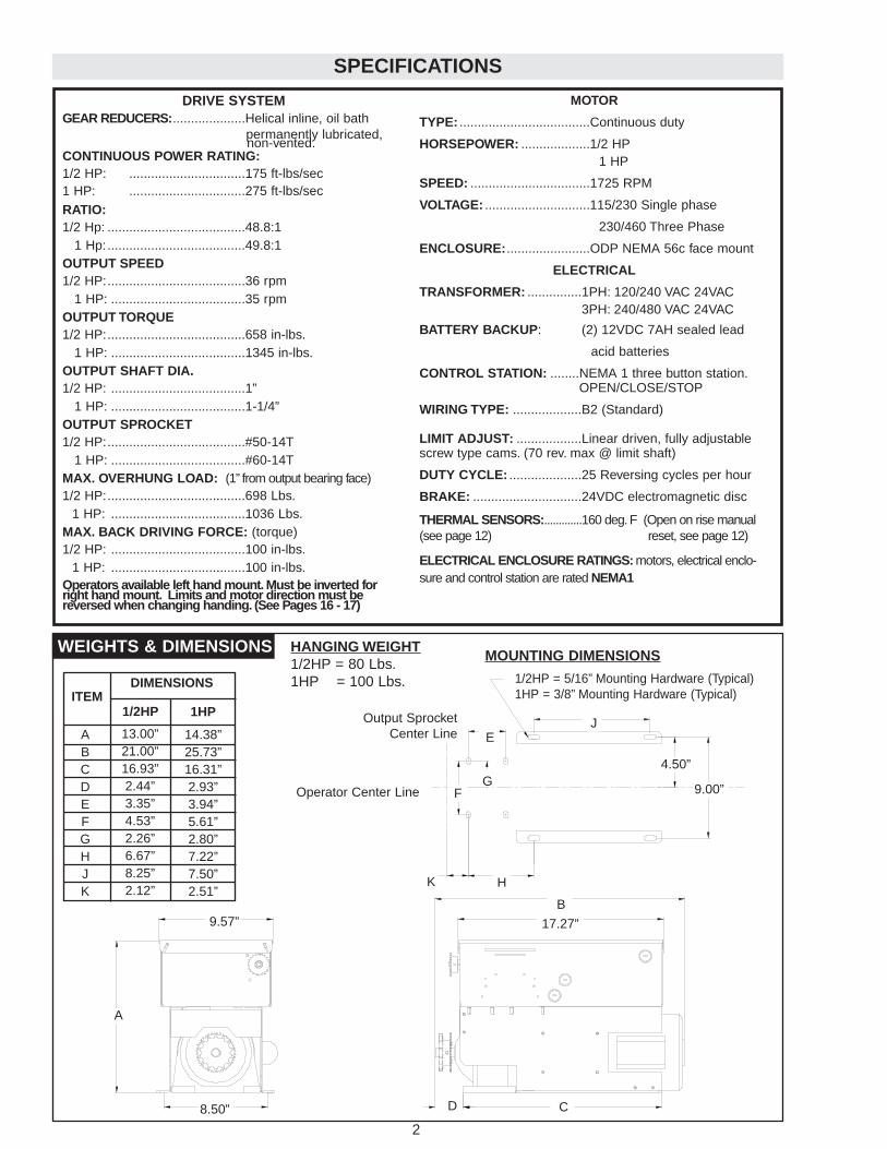
SPECIFICATIONS
17.27”
9.00”
A
9.57”
8.50”
MOUNTING DIMENSIONS
1/2HP = 5/16” Mounting Hardware (Typical)1HP = 3/8” Mounting Hardware (Typical)
DRIVE SYSTEMGEAR REDUCERS:....................Helical inline, oil bath
permanently lubricated,non-vented.
CONTINUOUS POWER RATING:1/2 HP: ................................175 ft-lbs/sec1 HP: ................................275 ft-lbs/secRATIO:1/2 Hp: ......................................48.8:1
1 Hp: ......................................49.8:1OUTPUT SPEED 1/2 HP:......................................36 rpm
1 HP: .....................................35 rpmOUTPUT TORQUE 1/2 HP:......................................658 in-lbs.
1 HP: .....................................1345 in-lbs.OUTPUT SHAFT DIA.1/2 HP: .....................................1”
1 HP: .....................................1-1/4”OUTPUT SPROCKET1/2 HP:......................................#50-14T
1 HP: .....................................#60-14TMAX. OVERHUNG LOAD: (1” from output bearing face)1/2 HP:......................................698 Lbs.
1 HP: .....................................1036 Lbs.MAX. BACK DRIVING FORCE: (torque)1/2 HP: .....................................100 in-lbs.
1 HP: .....................................100 in-lbs.Operators available left hand mount. Must be inverted forright hand mount. Limits and motor direction must bereversed when changing handing. (See Pages 16 - 17)
MOTOR
TYPE: ....................................Continuous duty
HORSEPOWER: ...................1/2 HP1 HP
SPEED: .................................1725 RPM
VOLTAGE: .............................115/230 Single phase
230/460 Three Phase
ENCLOSURE:.......................ODP NEMA 56c face mount
ELECTRICAL
TRANSFORMER: ...............1PH: 120/240 VAC 24VAC3PH: 240/480 VAC 24VAC
BATTERY BACKUP: (2) 12VDC 7AH sealed lead
acid batteries
CONTROL STATION: ........NEMA 1 three button station.OPEN/CLOSE/STOP
WIRING TYPE: ...................B2 (Standard)
LIMIT ADJUST: ..................Linear driven, fully adjustablescrew type cams. (70 rev. max @ limit shaft)
DUTY CYCLE: ....................25 Reversing cycles per hour
BRAKE: ..............................24VDC electromagnetic disc
THERMAL SENSORS:.............160 deg.F (Open on rise manual(see page 12) reset, see page 12)
ELECTRICAL ENCLOSURE RATINGS: motors, electrical enclo-sure and control station are rated NEMA1
1/2HP 1HP
ABCDEFGHJK
13.00”21.00”16.93”2.44”3.35”4.53”2.26”6.67”8.25”2.12”
14.38”25.73”16.31”2.93”3.94”5.61”2.80”7.22”7.50”2.51”
ITEMDIMENSIONS
B
D C
4.50”
J
K H
FG
E
WEIGHTS & DIMENSIONS HANGING WEIGHT1/2HP = 80 Lbs.1HP = 100 Lbs.
Operator Center Line
Output SprocketCenter Line
23
ILLUSTRATED PARTS – MODEL FDC
2
12
1
3
4
9
10
H2
H1H3
G4
11
8
5
G3
G2
6 B1
B2
G1
7
13
14
15
G5
3
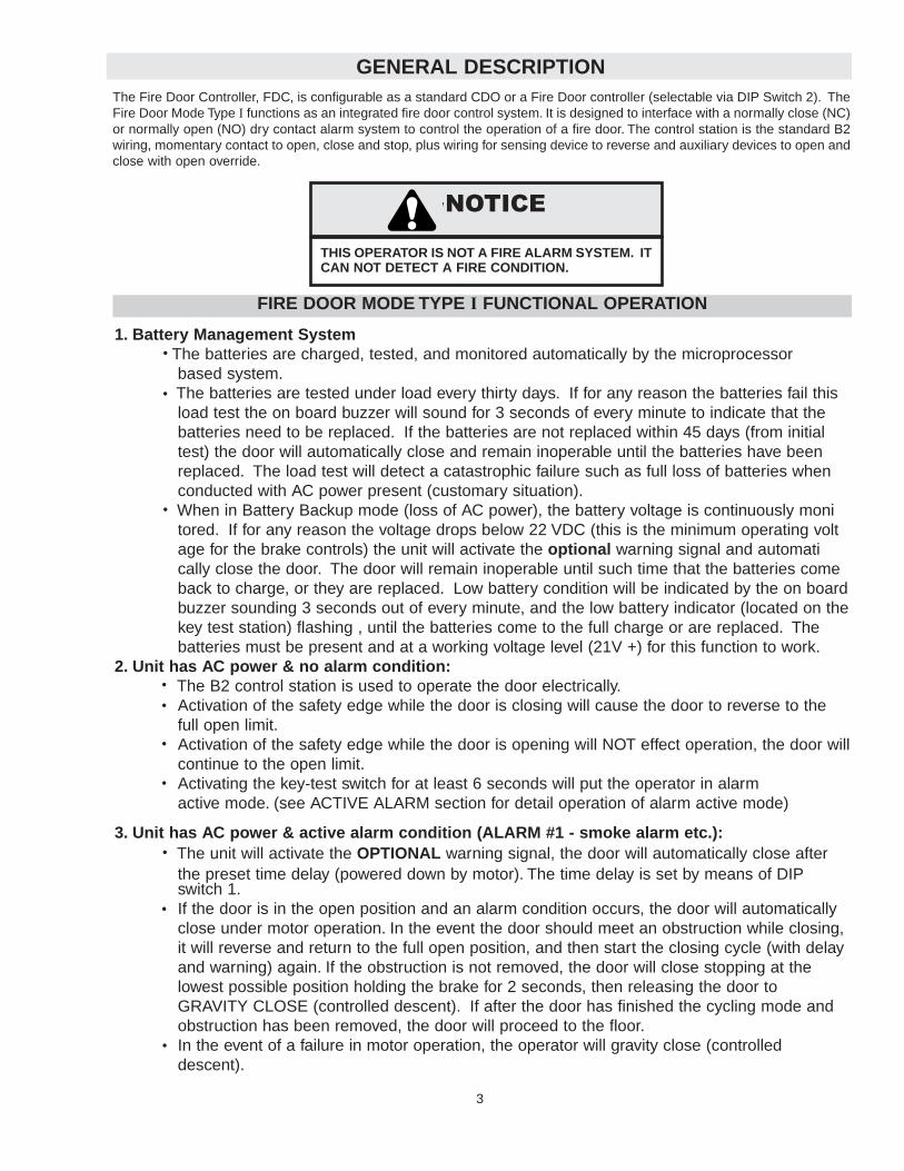
GENERAL DESCRIPTION
THIS OPERATOR IS NOT A FIRE ALARM SYSTEM. ITCAN NOT DETECT A FIRE CONDITION.
WARNING
CAUTION
WARNING
WARNING
The Fire Door Controller, FDC, is configurable as a standard CDO or a Fire Door controller (selectable via DIP Switch 2). TheFire Door Mode Type I functions as an integrated fire door control system. It is designed to interface with a normally close (NC)or normally open (NO) dry contact alarm system to control the operation of a fire door. The control station is the standard B2wiring, momentary contact to open, close and stop, plus wiring for sensing device to reverse and auxiliary devices to open andclose with open override.
FIRE DOOR MODE TYPE I FUNCTIONAL OPERATION
1. Battery Management SystemThe batteries are charged, tested, and monitored automatically by the microprocessor based system.The batteries are tested under load every thirty days. If for any reason the batteries fail this load test the on board buzzer will sound for 3 seconds of every minute to indicate that the batteries need to be replaced. If the batteries are not replaced within 45 days (from initial test) the door will automatically close and remain inoperable until the batteries have been replaced. The load test will detect a catastrophic failure such as full loss of batteries when conducted with AC power present (customary situation).When in Battery Backup mode (loss of AC power), the battery voltage is continuously monitored. If for any reason the voltage drops below 22 VDC (this is the minimum operating voltage for the brake controls) the unit will activate the optional warning signal and automatically close the door. The door will remain inoperable until such time that the batteries come back to charge, or they are replaced. Low battery condition will be indicated by the on boardbuzzer sounding 3 seconds out of every minute, and the low battery indicator (located on thekey test station) flashing , until the batteries come to the full charge or are replaced. The batteries must be present and at a working voltage level (21V +) for this function to work.
2. Unit has AC power & no alarm condition:The B2 control station is used to operate the door electrically.Activation of the safety edge while the door is closing will cause the door to reverse to the full open limit.Activation of the safety edge while the door is opening will NOT effect operation, the door willcontinue to the open limit.Activating the key-test switch for at least 6 seconds will put the operator in alarm active mode. (see ACTIVE ALARM section for detail operation of alarm active mode)
3. Unit has AC power & active alarm condition (ALARM #1 - smoke alarm etc.):The unit will activate the OPTIONAL warning signal, the door will automatically close after the preset time delay (powered down by motor). The time delay is set by means of DIPswitch 1.If the door is in the open position and an alarm condition occurs, the door will automatically close under motor operation. In the event the door should meet an obstruction while closing, it will reverse and return to the full open position, and then start the closing cycle (with delay and warning) again. If the obstruction is not removed, the door will close stopping at the lowest possible position holding the brake for 2 seconds, then releasing the door to GRAVITY CLOSE (controlled descent). If after the door has finished the cycling mode andobstruction has been removed, the door will proceed to the floor.In the event of a failure in motor operation, the operator will gravity close (controlled descent).
NOTICE
22
REPAIR PARTS KITS – MODEL FDC
Refer to the parts lists below for replacement kits available for your operator. If optional modifications and/or acces-sories are included with your operator, certain components may be added or removed from these lists. Individualcomponents of each kit may not be available. Please consult a parts and service representative regarding avail-ability of individual components. Refer to page 24 for all repair part ordering information.
K32-16214 GEAR REDUCER 1/2HP ASSEMBLY KIT
ITEM PART # DESCRIPTION QTY
G1G2G3G4
Gear ReducerHex Bolt, 3/8”Lockwasher, 3/8”Flatwasher, 3/8”
1444
32-1621482-HN38-20G585-LS-3885-FW-38
INDIVIDUAL COMPONENTS
ITEM PART # DESCRIPTION QTY
1
2
3456
789
10
11
12
131415
Frame, Right (1/2HP Operators)Frame, Right (1HP Operators)Frame, Left (1/2HP Operators)Frame, Left (1HP Operators)Bracket, FrameBracket, Front & RearBracket, LiftingOutput Sprocket (1/2HP Operators)Output Sprocket (1HP Operators)Extension ShaftMotor Kit (See Motor Kits)Connector, 90 DegreeAnti-Short BushingConnector, StraightAnti-Short BushingBrake Conduit (1/2HP Operators)Brake Conduit (1HP Operators)Motor Conduit (1/2HP Operators)Motor Conduit (1HP Operators)Step KeySet Screw, #10Screw, #10-32 x 5/8”
111142211111111
6.5”8”
13”14”12
16
10-16158R10-16159R10-16158L10-16159L10-1614010-1616010-1648315-1633315-1624411-16112K20-XXXX28-1021928-1022028-1202928-1022028-10218
28-10218
80-1611382-NH10-0482-WX10-10T
K32-16234 GEAR REDUCER 1HP ASSEMBLY KIT
ITEM PART # DESCRIPTION QTY
G1G2G3G4G5
Gear ReducerHex Bolt, 3/8”Lockwasher, 3/8”Flatwasher, 3/8”Flange nut, 3/8”
14444
32-1623482-HN38-20G585-LS-3885-FW-3884-FN38
K08-16114 INTERFACE HOUSING ASSEMBLY KIT
ITEM PART # DESCRIPTION QTY
H1H2H3
Interface HousingHex Bolt, 3/8”Lockwasher, 3/8”
144
08-1611482-HN38-1685-LS-38
K75-16512 BRAKE ASSEMBLY KIT
ITEM PART # DESCRIPTION QTY
B1B2
Electromagnetic BrakeSocket Head Screw, #10
14
36-1622182-SH10-06S
MOTOR KITS
K20-1050C2 Models FDC5011, FDC 5021K20-3050C4 Models FDC5023, FDC5043 K20-1100C2 Models FDC1011, FDC1021K20-3100C4 Models FDC1023, FDC1043
ACCESSORIES
02-109FDC Key Test Station 102-103 3 Button Station 171-17148 Fuse Link Retrofit Kit (See page 13) 174-16685 Thermal Sensor Assembly 2
Complete Electrical Box Replacement Kits To order a complete electrical box replacement kit, add a K-prefix to the model number of your operator. For example:
FDC5011 = K-FDC5011
* Electrical Box Kits include parts K72-16327 and K75-16515
E2
E7
E11
E13
E8
E12
E15
E10
E4
E5
E14
L7
E18
E19
E3
L6
E1
E9
E17E7
L3
L5
L8
L1
L6
L4
L2
S9
S7
S3
S6
E6
S5S2
S8
S4
S1
E17
E20
4
FUNCTIONAL OPERATION CONTINUED
4. Unit has AC power & active alarm condition (ALARM #2 - Fire Sensor, thermal sensor, fuse link.):The unit will activate the optional warning signal (siren/strobe), the door will automatically close after the pre set time delay. (powered down by motor) The time delay is set by means of DIP switch 1.If the door is in the open position and the alarm condition occurs, the door will automatically close under motor operation. In the event the door should meet an obstruction while closing, the door will stop for 2 seconds, then release the door to Gravity Close (controlled descent). After the obstruction has been removed,the door will proceed to the floor.In the event of a failure in motor operation, the operator will gravity close (controlled descent) All control station functions will be rendered inactive in this condition.The safety edge will remain active.
5. Unit has No AC power & No active alarm condition:The Close and Stop buttons of the B2 control station are functional.The door's descending speed is controlled by the integrated braking system.The door will stop if an obstruction is encountered while closing.The Open button is not functional
6. Unit has No AC power & active alarm condition (Alarm #1 or Alarm #2):The unit will activate the OPTIONAL warning signal (siren/strobe), the door will automatically close after thepreset time delay. (controlled by integrated braking system) The time delay is set by means of DIP switch 1.If the door encounters an obstruction while closing , the door will stop on the obstruction, and release the brake after (2) seconds. If the obstruction is then removed the unit will perform a controlled drop of the door. (not powered down by the motor)
7. Activation of the internal Thermal Sensor:Will activate an alarm #2 switch.With AC power present the unit will react as stated in paragraph 4.With No AC power present the unit will react as stated in paragraph 6.
8. Activation of the Key Test Station:Key must be activated for 6 secondsThe unit will activate the OPTIONAL warning signal (siren/strobe), the door will automatically close after the preset time delay. (controlled by integrated braking system) The time delay is set by means of DIP switch 1. (to test the signal devices and the delay time)
The door will close using gravity close mode (Controlled Descent) in order to test the door balance, descent speed, and the moment of the door.All sensing devices and control devices will be active. (In order to test these devices)
(See page 5 for procedures)
21
ILLUSTRATED PARTS – ELECTRICAL BOX
20
Before beginning any testing, secure the door area, keep unauthorized personnel from entering the area during testing.Be sure ac power is present at the operator, (the green "AC" led will be lighted on the operators control board) and thatthe batteries are connected and fully charged. (the red "DC" led will NOT be lighted on the operators control board)
1. Begin the test with your door at the full "OPEN" position.
2. Make certain dip switch #2 is in the "ON" position "FIREDOOR TYPE I" mode.
3. If your door is equipped with safety photo eyes, make certain dip switch #4 is in the "ON" position.
Note: If 2 minutes total time elapses from the beginning of step #11and the conclusion of step #15, the unit will automat-ically exit the "TEST" mode. To re-enter the "TEST" mode repeat step #4, and continue testing.
4. Turn the wall mounted key test switch to the "TEST" position and hold for a minimum of 6 seconds. This action simu-lates an “ALARM” signal.
5. If dip switch #1 is in the "ON" position, the door should begin to close immediately. If dip switch #1 is in the "OFF"position, the door should begin to close after 10 seconds time has elapsed. (the door will not motor down, it will gravitydescend)
6. Using a "stop-watch" verify that your door is closing between 6" and 24" per second. (i.e.. A 10ft high door shouldclose in a time between 5 and 20 seconds.) Your door should now be fully closed.
7. Open the door by depressing the "OPEN" button on the three button control station.
8. Repeat step #4.
9. When the door is approximately 3 to4 feet from the floor, activate the doors safety edge,(if so equipped) using a crate, skid or alike. Do not introduce any part of your body to the door system during testing. The door shouldreverse to the full open position. Remove the obstruction.
10. The door will begin to close within 1 sec., If dip switch #1 is in the "ON" position. If dip switch # 1 is in the "OFF"position, the door will wait 10 sec. Before beginning to close. The door should fully close to the floor. (the door will notmotor down, it will gravity descend)
11. Repeat steps #7 and #8.
12. When the door is approximately ½ way to the floor, interrupt the safety photo eye beam,(if so equipped) byblocking with a piece of cardboard or alike. Do not introduce any part of your body to the door system during testing. The door should reverse to the full open position.Remove the obstruction.
13. Step #10 repeats.
14. When the door is approximately ½ way to the floor, depress and hold the "STOP" button on the three button controlstation. The door should stop.
15. Release the "STOP" button on the control station. Step #10 repeats.
16. Depress the "OPEN" button on the three button control station. The door should open to the full open position. Theunit is now ready to be returned to service.
DOOR SYSTEM TESTING PROCEDURES
5
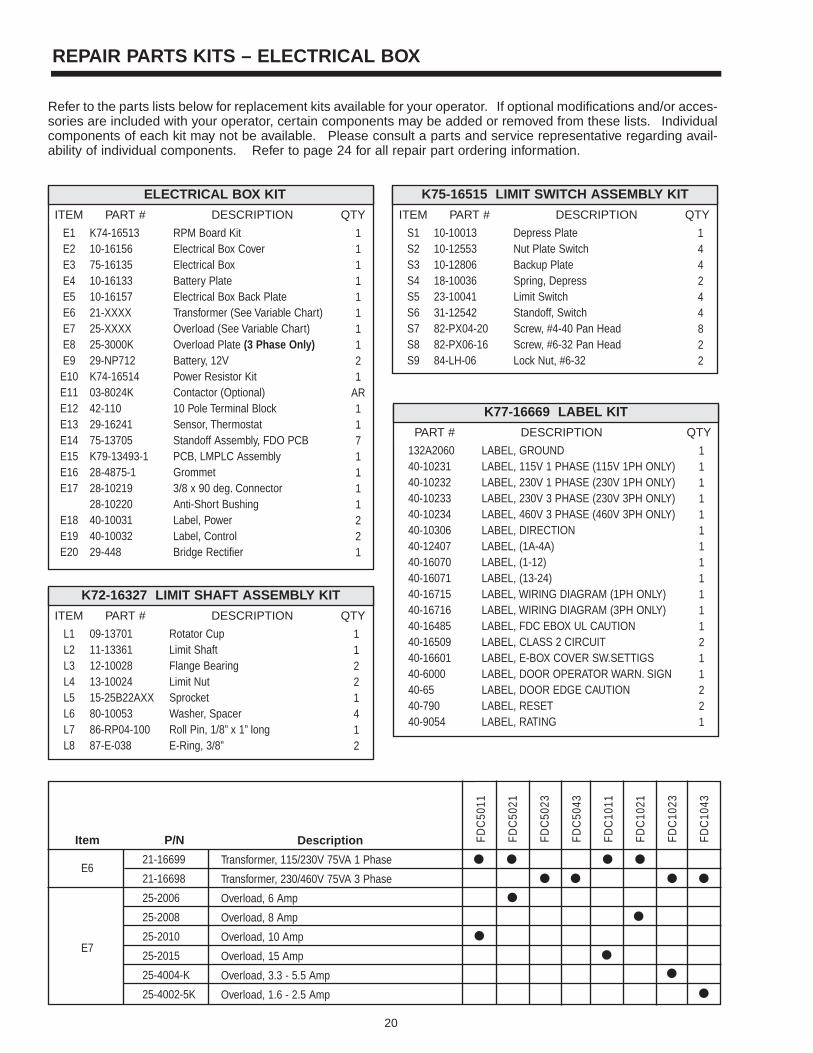
REPAIR PARTS KITS – ELECTRICAL BOX
Refer to the parts lists below for replacement kits available for your operator. If optional modifications and/or acces-sories are included with your operator, certain components may be added or removed from these lists. Individualcomponents of each kit may not be available. Please consult a parts and service representative regarding avail-ability of individual components. Refer to page 24 for all repair part ordering information.
K72-16327 LIMIT SHAFT ASSEMBLY KIT
ITEM PART # DESCRIPTION QTY
L1L2L3L4L5L6L7L8
Rotator CupLimit ShaftFlange BearingLimit NutSprocket Washer, SpacerRoll Pin, 1/8” x 1” longE-Ring, 3/8”
11221412
09-1370111-1336112-1002813-1002415-25B22AXX80-1005386-RP04-10087-E-038
K75-16515 LIMIT SWITCH ASSEMBLY KIT
ITEM PART # DESCRIPTION QTY
S1S2S3S4S5S6S7S8S9
Depress PlateNut Plate SwitchBackup PlateSpring, DepressLimit SwitchStandoff, SwitchScrew, #4-40 Pan HeadScrew, #6-32 Pan HeadLock Nut, #6-32
144244822
10-1001310-1255310-1280618-1003623-1004131-1254282-PX04-2082-PX06-1684-LH-06
ELECTRICAL BOX KIT
ITEM PART # DESCRIPTION QTY
E1E2E3E4E5E6E7E8E9
E10E11E12E13E14E15E16E17
E18E19E20
RPM Board KitElectrical Box CoverElectrical BoxBattery PlateElectrical Box Back PlateTransformer (See Variable Chart)Overload (See Variable Chart)Overload Plate (3 Phase Only)Battery, 12VPower Resistor KitContactor (Optional)10 Pole Terminal BlockSensor, ThermostatStandoff Assembly, FDO PCBPCB, LMPLC AssemblyGrommet3/8 x 90 deg. ConnectorAnti-Short BushingLabel, PowerLabel, ControlBridge Rectifier
1111111121
AR1171111221
K74-1651310-1615675-1613510-1613310-1615721-XXXX25-XXXX25-3000K29-NP712K74-1651403-8024K42-11029-1624175-13705K79-13493-128-4875-128-1021928-1022040-1003140-1003229-448
P/N
21-16699
21-16698
25-2006
25-2008
25-2010
25-2015
25-4004-K
25-4002-5K
Item
E6
E7
Description
Transformer, 115/230V 75VA 1 Phase
Transformer, 230/460V 75VA 3 Phase
Overload, 6 Amp
Overload, 8 Amp
Overload, 10 Amp
Overload, 15 Amp
Overload, 3.3 - 5.5 Amp
Overload, 1.6 - 2.5 Amp
FDC
5011
FDC
5021
FDC
5023
FDC
5043
FDC
1011
FDC
1021
FDC
1023
FDC
1043
K77-16669 LABEL KIT
PART # DESCRIPTION QTY
LABEL, GROUNDLABEL, 115V 1 PHASE (115V 1PH ONLY)LABEL, 230V 1 PHASE (230V 1PH ONLY)LABEL, 230V 3 PHASE (230V 3PH ONLY)LABEL, 460V 3 PHASE (460V 3PH ONLY)LABEL, DIRECTIONLABEL, (1A-4A)LABEL, (1-12)LABEL, (13-24)LABEL, WIRING DIAGRAM (1PH ONLY) LABEL, WIRING DIAGRAM (3PH ONLY)LABEL, FDC EBOX UL CAUTIONLABEL, CLASS 2 CIRCUITLABEL, E-BOX COVER SW.SETTIGSLABEL, DOOR OPERATOR WARN. SIGNLABEL, DOOR EDGE CAUTIONLABEL, RESETLABEL, RATING
111111111111211221
132A206040-1023140-1023240-1023340-1023440-1030640-1240740-1607040-1607140-1671540-1671640-1648540-1650940-1660140-600040-6540-79040-9054
196
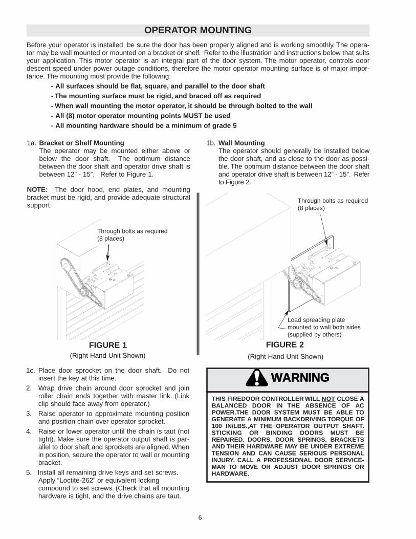
1b. Wall MountingThe operator should generally be installed belowthe door shaft, and as close to the door as possi-ble. The optimum distance between the door shaftand operator drive shaft is between 12” - 15”. Referto Figure 2.
OPERATOR MOUNTING
1a. Bracket or Shelf Mounting The operator may be mounted either above orbelow the door shaft. The optimum distancebetween the door shaft and operator drive shaft isbetween 12” - 15”. Refer to Figure 1.
NOTE: The door hood, end plates, and mountingbracket must be rigid, and provide adequate structuralsupport.
1c. Place door sprocket on the door shaft. Do notinsert the key at this time.
2. Wrap drive chain around door sprocket and joinroller chain ends together with master link. (Linkclip should face away from operator.)
3. Raise operator to approximate mounting positionand position chain over operator sprocket.
4. Raise or lower operator until the chain is taut (nottight). Make sure the operator output shaft is par-allel to door shaft and sprockets are aligned. Whenin position, secure the operator to wall or mountingbracket.
5. Install all remaining drive keys and set screws.Apply “Loctite-262” or equivalent locking compound to set screws. (Check that all mountinghardware is tight, and the drive chains are taut.
FIGURE 1 FIGURE 2
Before your operator is installed, be sure the door has been properly aligned and is working smoothly. The opera-tor may be wall mounted or mounted on a bracket or shelf. Refer to the illustration and instructions below that suitsyour application. This motor operator is an integral part of the door system. The motor operator, controls doordescent speed under power outage conditions, therefore the motor operator mounting surface is of major impor-tance. The mounting must provide the following:
- All surfaces should be flat, square, and parallel to the door shaft- The mounting surface must be rigid, and braced off as required- When wall mounting the motor operator, it should be through bolted to the wall- All (8) motor operator mounting points MUST be used- All mounting hardware should be a minimum of grade 5
THIS FIREDOOR CONTROLLER WILL NONOTT CLOSE ABALANCED DOOR IN THE ABSENCE OF ACPOWER.THE DOOR SYSTEM MUST BE ABLE TOGENERATE A MINIMUM BACKDRIVING TORQUE OF100 IN/LBS.,AT THE OPERATOR OUTPUT SHAFT.STICKING OR BINDING DOORS MUST BEREPAIRED. DOORS, DOOR SPRINGS, BRACKETSAND THEIR HARDWARE MAY BE UNDER EXTREMETENSION AND CAN CAUSE SERIOUS PERSONALINJURY. CALL A PROFESSIONAL DOOR SERVICE-MAN TO MOVE OR ADJUST DOOR SPRINGS ORHARDWARE.
WARNING
CAUTION
WARNING
WARNING
Through bolts as required(8 places)
Load spreading plate mounted to wall both sides(supplied by others)
(Right Hand Unit Shown)(Right Hand Unit Shown)
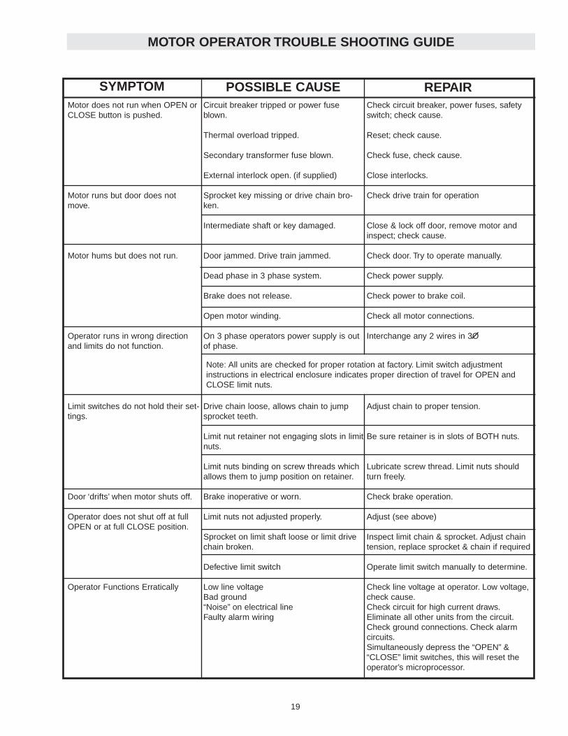
MOTOR OPERATOR TROUBLE SHOOTING GUIDE
Motor does not run when OPEN orCLOSE button is pushed.
Motor runs but door does notmove.
Motor hums but does not run.
Operator runs in wrong directionand limits do not function.
Limit switches do not hold their set-tings.
Door ‘drifts’ when motor shuts off.
Operator does not shut off at fullOPEN or at full CLOSE position.
Operator Functions Erratically
Check circuit breaker, power fuses, safetyswitch; check cause.
Reset; check cause.
Check fuse, check cause.
Close interlocks.
Check drive train for operation
Close & lock off door, remove motor andinspect; check cause.
Check door. Try to operate manually.
Check power supply.
Check power to brake coil.
Check all motor connections.
Interchange any 2 wires in 3O
Adjust chain to proper tension.
Be sure retainer is in slots of BOTH nuts.
Lubricate screw thread. Limit nuts shouldturn freely.
Check brake operation.
Adjust (see above)
Inspect limit chain & sprocket. Adjust chaintension, replace sprocket & chain if required
Operate limit switch manually to determine.
Check line voltage at operator. Low voltage,check cause.Check circuit for high current draws.Eliminate all other units from the circuit.Check ground connections. Check alarmcircuits.Simultaneously depress the “OPEN” &“CLOSE” limit switches, this will reset theoperator’s microprocessor.
Circuit breaker tripped or power fuseblown.
Thermal overload tripped.
Secondary transformer fuse blown.
External interlock open. (if supplied)
Sprocket key missing or drive chain bro-ken.
Intermediate shaft or key damaged.
Door jammed. Drive train jammed.
Dead phase in 3 phase system.
Brake does not release.
Open motor winding.
On 3 phase operators power supply is outof phase.
Drive chain loose, allows chain to jumpsprocket teeth.
Limit nut retainer not engaging slots in limitnuts.
Limit nuts binding on screw threads whichallows them to jump position on retainer.
Brake inoperative or worn.
Limit nuts not adjusted properly.
Sprocket on limit shaft loose or limit drivechain broken.
Defective limit switch
Low line voltage Bad ground“Noise” on electrical lineFaulty alarm wiring
Note: All units are checked for proper rotation at factory. Limit switch adjustmentinstructions in electrical enclosure indicates proper direction of travel for OPEN andCLOSE limit nuts.
SYMPTOM POSSIBLE CAUSE REPAIR
Through bolts as required(8 places)
7
PHOTO EYES
NOTE: LiftMaster recommends the use of safetyphoto eyes as a non-contact method of entrapmentprotection.
The operator has been manufactured to accept directconnection of LiftMaster Infrared Eyes. See page 11for proper dip switch settings, and pages 14 & 15 forwiring connections. Follow the wiring instructions sup-plied with your LiftMaster Infrared Eyes.
ENTRAPMENT PROTECTION ACCESSORIES
TO AVOID SERIOUS PERSONAL INJURY OR DEATHFROM ELECTROCUTION, DISCONNECT ELECTRICPOWER BEFORE MANUALLY MOVING LIMIT NUTS.
WARNING
CAUTION
WARNING
WARNING
LIMIT SWITCH ADJUSTMENT
MAKE SURE THE LIMIT NUTS ARE POSITIONED BETWEEN THE LIMIT SWITCH ACTUATORS BEFOREPROCEEDING WITH ADJUSTMENTS. BE CERTAIN THAT DIP SWITCH #2 IS IN THE “OFF” POSITION (CDOMODE) BEFORE MAKING ADJUSTMENTS.
If other problems persist, call our toll-free number forassistance - 1-800-528-2806
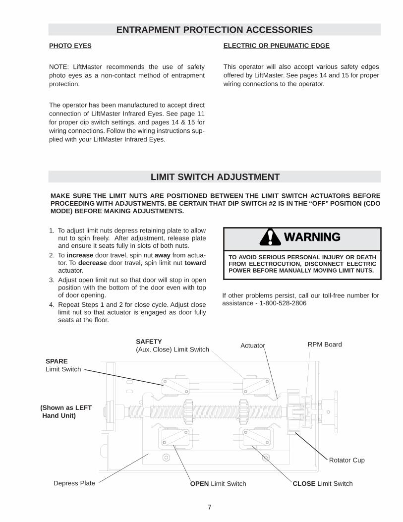
1. To adjust limit nuts depress retaining plate to allownut to spin freely. After adjustment, release plateand ensure it seats fully in slots of both nuts.
2. To increase door travel, spin nut away from actua-tor. To decrease door travel, spin limit nut towardactuator.
3. Adjust open limit nut so that door will stop in openposition with the bottom of the door even with topof door opening.
4. Repeat Steps 1 and 2 for close cycle. Adjust closelimit nut so that actuator is engaged as door fullyseats at the floor.
Depress Plate CLOSE Limit Switch
SAFETY(Aux. Close) Limit Switch
OPEN Limit Switch
Actuator RPM Board
Rotator Cup
(Shown as LEFTHand Unit)
SPARELimit Switch
18
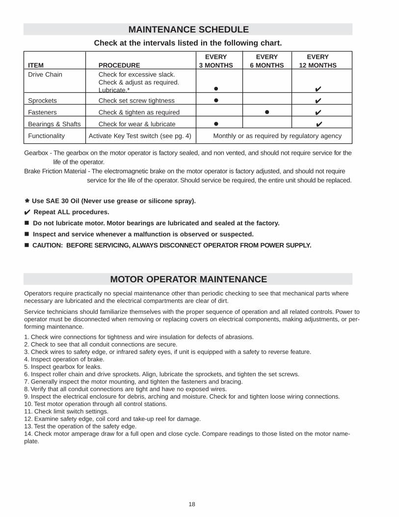
MAINTENANCE SCHEDULE
* Use SAE 30 Oil (Never use grease or silicone spray).
✔✔ Repeat ALL procedures.
Do not lubricate motor. Motor bearings are lubricated and sealed at the factory.
Inspect and service whenever a malfunction is observed or suspected.
CAUTION: BEFORE SERVICING, ALWAYS DISCONNECT OPERATOR FROM POWER SUPPLY.
Check at the intervals listed in the following chart.
EVERY EVERY EVERYITEM PROCEDURE 3 MONTHS 6 MONTHS 12 MONTHSDrive Chain Check for excessive slack.
Check & adjust as required.Lubricate.* ✔✔
Sprockets Check set screw tightness ✔✔
Fasteners Check & tighten as required ✔✔
Bearings & Shafts Check for wear & lubricate ✔✔
Functionality Activate Key Test switch (see pg. 4) Monthly or as required by regulatory agency
Gearbox - The gearbox on the motor operator is factory sealed, and non vented, and should not require service for thelife of the operator.
Brake Friction Material - The electromagnetic brake on the motor operator is factory adjusted, and should not require service for the life of the operator. Should service be required, the entire unit should be replaced.
Operators require practically no special maintenance other than periodic checking to see that mechanical parts wherenecessary are lubricated and the electrical compartments are clear of dirt.
Service technicians should familiarize themselves with the proper sequence of operation and all related controls. Power tooperator must be disconnected when removing or replacing covers on electrical components, making adjustments, or per-forming maintenance.
1. Check wire connections for tightness and wire insulation for defects of abrasions.2. Check to see that all conduit connections are secure.3. Check wires to safety edge, or infrared safety eyes, if unit is equipped with a safety to reverse feature.4. Inspect operation of brake.5. Inspect gearbox for leaks.6. Inspect roller chain and drive sprockets. Align, lubricate the sprockets, and tighten the set screws.7. Generally inspect the motor mounting, and tighten the fasteners and bracing.8. Verify that all conduit connections are tight and have no exposed wires.9. Inspect the electrical enclosure for debris, arching and moisture. Check for and tighten loose wiring connections.10. Test motor operation through all control stations.11. Check limit switch settings.12. Examine safety edge, coil cord and take-up reel for damage.13. Test the operation of the safety edge.14. Check motor amperage draw for a full open and close cycle. Compare readings to those listed on the motor name-plate.
MOTOR OPERATOR MAINTENANCE
ELECTRIC OR PNEUMATIC EDGE
This operator will also accept various safety edgesoffered by LiftMaster. See pages 14 and 15 for properwiring connections to the operator.

178
The motor operator is manufactured as a standard commercial operator with standard B2wiring functionality. Once installation is completed and all alarm devices are connected,and tested, the installer must then switch the dip switch setting (See page 11). Upon com-pletion of installation, the unit’s functionality should be checked by activating the key teststation (See page 5).If for any reason your unit does not respond as described in this man-ual, check that you have read and followed all installation and operating instructions. If dif-ficulties persist contact the Lift-Master technical hotline.
1-800-528-2806.
Alarm Inputs:Alarm Input #1: Used for electronic alarm devices such as smoke detection devices or similaralarm systems. Devices may be N/O or N/C. Switchable using DIP Switch #3. This alarm will acti-vate a motored closure of the door, and all sensing and control devices will remain active.It is imperative that the alarm signal contact is maintained for a time period greater than the alarmdelay to close setting. I.E. If dip switch #1 is in the “OFF” position (10 seconds) the alarm systemmust supply a “DRY” contact signal to terminals J2-11 & J2-12 for a minimum of 12 seconds.
Alarm Input #2: Used for the thermal sensors (electronic fusible links) or similar systems. (N.C.state only) This alarm condition will activate a motored closure of the door, and all sensingdevices and control stations will be rendered inactive. EXCEPT THE SAFETY EDGE. This alarmwill override any other alarm condition or input.
NOTICE:This equipment has been tested and found to comply with the limits for a Class A digital device, pursuantto Part 15 of the FCC Rules. These limits are designed to provide reasonable protection against harmfulinterference when the equipment is operated in a commercial environment. This equipment generates,uses, and can radiate radio frequency energy and, if not installed and used in accordance with the instruc-tion manual, may cause harmful interference to radio communications. Operation of this equipment in a res-idential area is likely to cause harmful interference, in which case the user will be required to correct theinterference at his own expense.
INSTALLATION MODE
IT IS THE END USERS SOLE RESPONSIBILITY TO CHECKTHAT ALL SYSTEMS ARE INSTALLED AND FUNCTIONAL.THE MOTOR OPERATOR MUST BE SWITCHED TO THE“FIREDOOR MODE TYPE I”TO ENABLE ALL ALARM, ANDWARNING SYSTEMS. DIP SWITCH #2 MUST BE SWITCHEDTO THE “ON” POSITION TO ENABLE THE “FIREDOOR”MODE. FAILURE TO DO SO, COULD RESULT IN LOSS OFLIFE AND PROPERTY.
WARNING
CAUTION
WARNING
WARNING
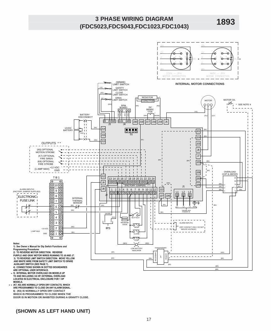
(FDC5023,FDC5043,FDC1023,FDC1043) 3 PHASE WIRING DIAGRAM 1893
J12
J9
J8 1 2 3 4 5 6 7 8 9 10 11 12
13 14 15 16 17 18 19 20 21 22 23 24
J27 J26
J22
J2L1 L2 L3
J1J29
J20
J28
J25
J7
J6
J23
J24
J21
J16 J19 J5
J13
J15
J14
J18 J17J30J3 J4
S1
RPM BOARD
BRAKECOIL
(WH) (WH/BK)
DC
SAFETY LIMIT SWITCH
CLOSELIMIT SWITCH
OPENLIMIT SWITCH
(YE)
(BL)
(RD)
(WH)
(BK)
(RD)
-
+
-
+
12VDCBATTERY
DISCONNECTBATTERY
RESISTOR
CAPACITOR
(BK) (RD)
(BL)L1 L2 L3 GND
230/460 3PHPOWER IN
(YE)
(PU) (GY)
(1HP & ABOVE)
L1
L2
L3
T1
T2
T3
96
95
(BK)
(BK)
(BK)
OVERLOAD
(BK)
(BK)
(BK)
(BK) (BK)
(FACTORY JUMPER)
(BK) (BK)
INTERNALTHERMALSENSOR
(BK)
MOTOR O/L
(BK)
(RD)
(BR)
(BR)
(BR)
TRANSFORMER
SE
CO
ND
AR
Y
PR
IMA
RY
1
(BR)
(BR)
(WH)
(WH)
(BK)
(BK)
(BK)
(BK)
IR'S
REVERSEEDGE
STOP
CLOSE
OPEN
KEY-TEST
C NO
LOW BATTERY INDICATOR
(RD)(WH)
(K6) OPTIONALMOTION STROBE
(K7) OPTIONALFIRE SIREN
(K8) OPTIONALFIRE STROBE
+12 VDC GND
ALARM INPUT#1
(DRY CONTACT ONLY, DO NOT INDUCE VOLTAGE!)
(1 AMP MAX)
OUTPUTS * *
(WH/BK)
(WH)
- +
- +
SEE NOTE 4*
(GW
)
(YE
)
(RD
)
(WH
)
(BR)
(BK)
(BK)
(BK)
MOTOR
Notes:1) See Owner�s Manual for Dip Switch Functions andProgramming Procedures2) TO REVERSE MOTOR DIRECTION: REVERSEPURPLE AND GRAY MOTOR WIRES RUNNING TO J6 AND J7.
4) CONNECTIONS SHOWN IN DOTTED BOUNDARIESARE OPTIONAL USER INTERFACE. 5) INTERNAL MOTOR OVERLOAD ON MODELS UPTO AND INCLUDING 3/4 HP. EXTERNAL OVERLOAD LOCATED IN ELECTRICAL ENCLOSURE FOR 1 HP MODELS.(K7, K8) ARE NORMALLY OPEN DRY CONTACTS, WHICHARE PROGRAMMED TO CLOSE ON ANY ALARM SIGNAL.6) (K6) IS NORMALLY OPEN DRY CONTACT WHICH IS PROGRAMMED TO CLOSE WHEN THE DOOR IS IN MOTION OR INHIBITED DURING A GRAVITY CLOSE.
*
* *
(RD)
(BL)
ELECTRONICFUSE LINK
ALARM INPUT#2(FACTORY JUMPER SUPPLIED)
3) TO REVERSE LIMIT SWITCH DIRECTION: MOVE YELLOWAND WHITE WIRE FROM SAFETY LIMIT SWITCH TO SPAREAUXILIARY SWITCH (SEE PAGE 7).
(SPARE)LIMIT SWITCH
T B 1
+24 VDC
1 AMP MAX
10
9
8
7
6
5
4
3
2
1GRD
INTERNAL MOTOR CONNECTIONS
* *
(SHOWN AS LEFT HAND UNIT)
9
INSTALL POWER WIRING & CONTROL STATION
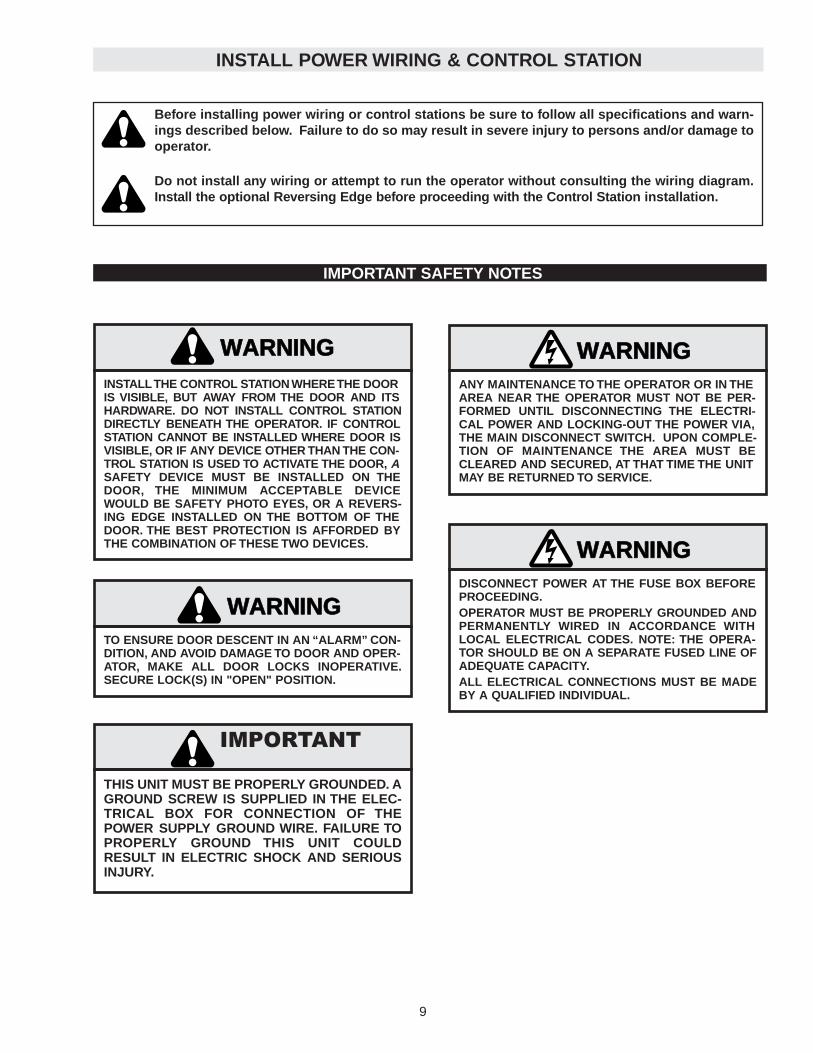
Before installing power wiring or control stations be sure to follow all specifications and warn-ings described below. Failure to do so may result in severe injury to persons and/or damage tooperator.
Do not install any wiring or attempt to run the operator without consulting the wiring diagram.Install the optional Reversing Edge before proceeding with the Control Station installation.
WARNING
CAUTION
WARNING
WARNING
DISCONNECT POWER AT THE FUSE BOX BEFOREPROCEEDING.OPERATOR MUST BE PROPERLY GROUNDED ANDPERMANENTLY WIRED IN ACCORDANCE WITHLOCAL ELECTRICAL CODES. NOTE: THE OPERA-TOR SHOULD BE ON A SEPARATE FUSED LINE OFADEQUATE CAPACITY.ALL ELECTRICAL CONNECTIONS MUST BE MADEBY A QUALIFIED INDIVIDUAL.
WARNING
CAUTION
WARNING
WARNING
TO ENSURE DOOR DESCENT IN AN “ALARM” CON-DITION, AND AVOID DAMAGE TO DOOR AND OPER-ATOR, MAKE ALL DOOR LOCKS INOPERATIVE.SECURE LOCK(S) IN "OPEN" POSITION.
IMPORTANT SAFETY NOTES
WARNING
CAUTION
WARNING
WARNING
ANY MAINTENANCE TO THE OPERATOR OR IN THEAREA NEAR THE OPERATOR MUST NOT BE PER-FORMED UNTIL DISCONNECTING THE ELECTRI-CAL POWER AND LOCKING-OUT THE POWER VIA,THE MAIN DISCONNECT SWITCH. UPON COMPLE-TION OF MAINTENANCE THE AREA MUST BECLEARED AND SECURED, AT THAT TIME THE UNITMAY BE RETURNED TO SERVICE.
WARNING
CAUTION
WARNING
WARNING
INSTALL THE CONTROL STATION WHERE THE DOORIS VISIBLE, BUT AWAY FROM THE DOOR AND ITSHARDWARE. DO NOT INSTALL CONTROL STATIONDIRECTLY BENEATH THE OPERATOR. IF CONTROLSTATION CANNOT BE INSTALLED WHERE DOOR ISVISIBLE, OR IF ANY DEVICE OTHER THAN THE CON-TROL STATION IS USED TO ACTIVATE THE DOOR, ASAFETY DEVICE MUST BE INSTALLED ON THEDOOR, THE MINIMUM ACCEPTABLE DEVICEWOULD BE SAFETY PHOTO EYES, OR A REVERS-ING EDGE INSTALLED ON THE BOTTOM OF THEDOOR. THE BEST PROTECTION IS AFFORDED BYTHE COMBINATION OF THESE TWO DEVICES.
WARNING
CAUTION
WARNING
WARNING
THIS UNIT MUST BE PROPERLY GROUNDED. AGROUND SCREW IS SUPPLIED IN THE ELEC-TRICAL BOX FOR CONNECTION OF THEPOWER SUPPLY GROUND WIRE. FAILURE TOPROPERLY GROUND THIS UNIT COULDRESULT IN ELECTRIC SHOCK AND SERIOUSINJURY.
IMPORTANT
16
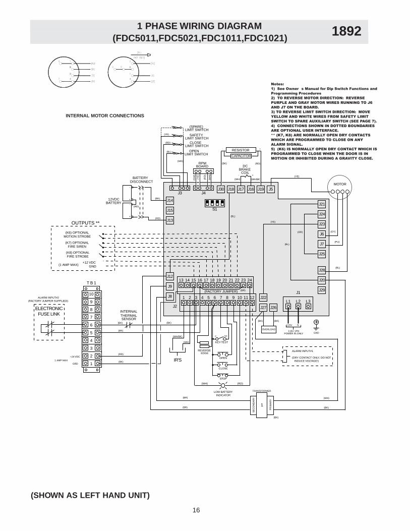
(FDC5011,FDC5021,FDC1011,FDC1021)1 PHASE WIRING DIAGRAM 1892
J12
J9
J8 1 2 3 4 5 6 7 8 9 10 11 12
13 14 15 16 17 18 19 20 21 22 23 24
J27 J26
J22
J2L1 L2 L3
J1J29
J20
J28
J25
J7
J6
J23
J24
J21
J16 J19 J5
J13
J15
J14
J18 J17J30J3 J4
S1
RPM BOARD
BRAKECOIL
(WH) (WH/BK)
DC
SAFETY LIMIT SWITCH
(SPARE)LIMIT SWITCH
CLOSELIMIT SWITCH
OPENLIMIT SWITCH
(YE)
(BL)
(RD)
(WH)
(BK)
(RD)
-
+
-
+
12VDCBATTERY
DISCONNECTBATTERY
RESISTOR
CAPACITOR
(BK) (RD)
115V N
GND115V 1PH
POWER IN ONLY
MOTOR
(YE)
(PU)
(GY)
(BL)
T B 1
(FACTORY JUMPER)
(BK) (BK)
INTERNALTHERMALSENSOR
(BK)
(BR)
(BR)
TRANSFORMER
SE
CO
ND
AR
Y
PR
IMA
RY
1
(WH)
(BK)
(BK)
IR'S
REVERSEEDGE
STOP
CLOSE
OPEN
KEY-TEST
C NO
LOW BATTERY INDICATOR
(RD)(WH)
ELECTRONICFUSE LINK
ALARM INPUT#2(FACTORY JUMPER SUPPLIED)
(K6) OPTIONALMOTION STROBE
(K7) OPTIONALFIRE SIREN
(K8) OPTIONALFIRE STROBE
+12 VDC GND
ALARM INPUT#1
(DRY CONTACT ONLY, DO NOT INDUCE VOLTAGE!)
(1 AMP MAX)
OUTPUTS **
+24 VDC
1 AMP MAX
(WH/BK)
(WH)
- +
- +
OVERLOAD
(BK)(BK)
(OR)
(YE)
(BL)
(BR)
(GW
)
(YE
)
(RD
)
(WH
)
Notes:1) See Owner�s Manual for Dip Switch Functions and Programming Procedures2) TO REVERSE MOTOR DIRECTION: REVERSE PURPLE AND GRAY MOTOR WIRES RUNNING TO J6 AND J7 ON THE BOARD.3) TO REVERSE LIMIT SWITCH DIRECTION: MOVE YELLOW AND WHITE WIRES FROM SAFETY LIMIT SWITCH TO SPARE AUXILIARY SWITCH (SEE PAGE 7).4) CONNECTIONS SHOWN IN DOTTED BOUNDARIESARE OPTIONAL USER INTERFACE.** (K7, K8) ARE NORMALLY OPEN DRY CONTACTS WHICH ARE PROGRAMMED TO CLOSE ON ANY ALARM SIGNAL.5) (K6) IS NORMALLY OPEN DRY CONTACT WHICH IS PROGRAMMED TO CLOSE WHEN THE DOOR IS IN MOTION OR INHIBITED DURING A GRAVITY CLOSE.
(RD)
(BL)
10
9
8
7
6
5
4
3
2
1GRD(BK)
(RD)
INTERNAL MOTOR CONNECTIONS
(SHOWN AS LEFT HAND UNIT)
1510
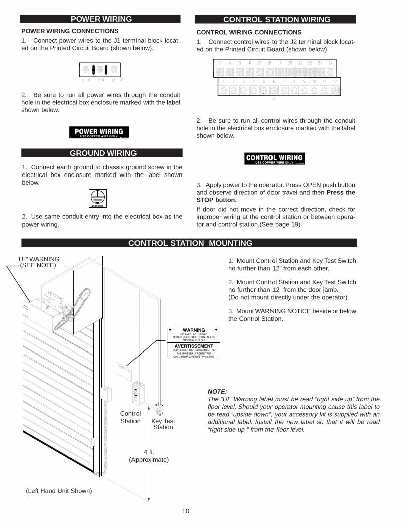
CONTROL STATION MOUNTING
POWER WIRING CONNECTIONS
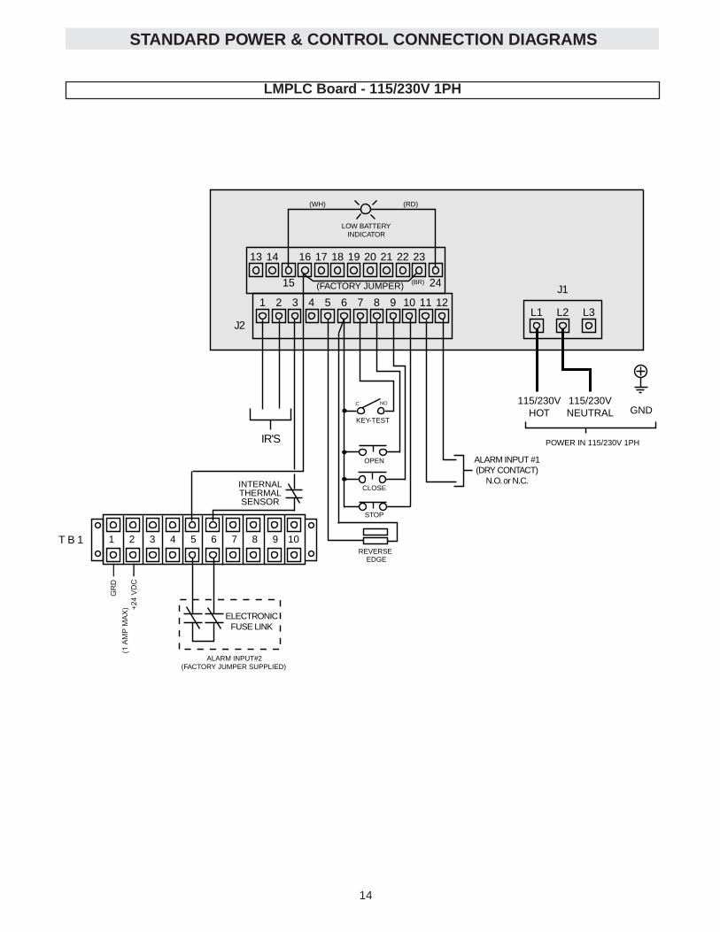
1. Connect power wires to the J1 terminal block locat-ed on the Printed Circuit Board (shown below).
2. Be sure to run all power wires through the conduithole in the electrical box enclosure marked with the labelshown below.
POWER WIRING CONTROL STATION WIRING
CONTROL WIRING CONNECTIONS
1. Connect control wires to the J2 terminal block locat-ed on the Printed Circuit Board (shown below).
2. Be sure to run all control wires through the conduithole in the electrical box enclosure marked with the labelshown below.
3. Apply power to the operator. Press OPEN push buttonand observe direction of door travel and then Press theSTOP button.
If door did not move in the correct direction, check forimproper wiring at the control station or between opera-tor and control station.(See page 19)
GROUND WIRING
1. Connect earth ground to chassis ground screw in theelectrical box enclosure marked with the label shownbelow.
2. Use same conduit entry into the electrical box as thepower wiring.
40-10033B
4 ft.(Approximate)
1. Mount Control Station and Key Test Switchno further than 12” from each other.
2. Mount Control Station and Key Test Switchno further than 12” from the door jamb.(Do not mount directly under the operator)
3. Mount WARNING NOTICE beside or belowthe Control Station.
ControlStation Key Test
Station
(Left Hand Unit Shown)
“UL” WARNING(SEE NOTE)
NOTE:The “UL” Warning label must be read “right side up” from thefloor level. Should your operator mounting cause this label tobe read “upside down”, your accessory kit is supplied with anadditional label. Install the new label so that it will be read“right side up “ from the floor level.
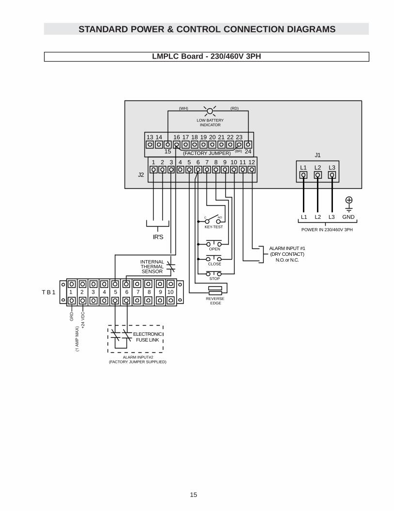
STANDARD POWER & CONTROL CONNECTION DIAGRAMS
LMPLC Board - 230/460V 3PH
1 2 3 4 5 6 7 8 9 10 11 12
13 14
15
16 17 18 19 20 21 22 23
24
J2L1 L2 L3
J1
L1 L2 L3 GND
POWER IN 230/460V 3PH
(FACTORY JUMPER)
IR'S
REVERSEEDGE
STOP
CLOSE
OPEN
KEY-TEST
C NO
LOW BATTERY INDICATOR
(RD)(WH)
(BR)
T B 1
ELECTRONICFUSE LINK
ALARM INPUT#2(FACTORY JUMPER SUPPLIED)
1 2 3 4 5 6 7 8 9 10
INTERNALTHERMALSENSOR
ALARM INPUT #1(DRY CONTACT)
N.O. or N.C.
+24
VD
C
GR
D(1
AM
P M
AX
)
14 11
1 2 3 4
ON (0 SECOND DELAY)
OFF (10 SECOND DELAY) 1 2 3 4
ON (IR'S ENABLED)
OFF (IR'S DISABLED)
1 2 3 4
ON (FIRE DOOR MODE TYPE I)
OFF (CDO MODE) 1 2 3 4
ON (N.C. ALARM)
OFF (N.O. ALARM)
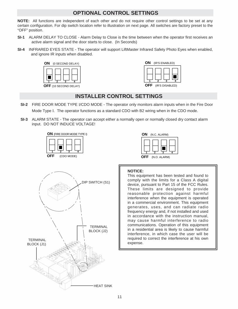
NOTICE:This equipment has been tested and found tocomply with the limits for a Class A digitaldevice, pursuant to Part 15 of the FCC Rules.These l imits are designed to providereasonable protection against harmfulinterference when the equipment is operatedin a commercial environment. This equipmentgenerates, uses, and can radiate radiofrequency energy and, if not installed and usedin accordance with the instruction manual,may cause harmful interference to radiocommunications. Operation of this equipmentin a residential area is likely to cause harmfulinterference, in which case the user will berequired to correct the interference at his ownexpense.
OPTIONAL CONTROL SETTINGSNOTE: All functions are independent of each other and do not require other control settings to be set at anycertain configuration. For dip switch location refer to illustration on next page. All switches are factory preset to the“OFF” position.
SI-1 ALARM DELAY TO CLOSE - Alarm Delay to Close is the time between when the operator first receives anactive alarm signal and the door starts to close. (In Seconds)
SI-4 INFRARED EYES STATE - The operator will support LiftMaster Infrared Safety Photo Eyes when enabled,and ignore IR inputs when disabled.
TERMINAL BLOCK (J2)
TERMINAL BLOCK (J1)
HEAT SINK
DIP SWITCH (S1)
INSTALLER CONTROL SETTINGSSI-2 FIRE DOOR MODE TYPE I/CDO MODE - The operator only monitors alarm inputs when in the Fire Door
Mode Type I. The operator functions as a standard CDO with B2 wiring when in the CDO mode.
SI-3 ALARM STATE - The operator can accept either a normally open or normally closed dry contact alarm input. DO NOT INDUCE VOLTAGE!
1 2 3 4 5 6 7 8 9 10 11 12
13 14
15
16 17 18 19 20 21 22 23
24
J2L1 L2 L3
J1
GND
POWER IN 115/230V 1PH
(FACTORY JUMPER)
IR'S
REVERSEEDGE
STOP
CLOSE
OPEN
KEY-TEST
C NO
LOW BATTERY INDICATOR
(RD)(WH)
(BR)
ALARM INPUT #1(DRY CONTACT)
N.O. or N.C.
115/230VHOT
115/230VNEUTRAL
T B 1
ELECTRONICFUSE LINK
ALARM INPUT#2(FACTORY JUMPER SUPPLIED)
1 2 3 4 5 6 7 8 9 10
INTERNALTHERMALSENSOR
+24
VD
C
GR
D(1
AM
P M
AX
)
STANDARD POWER & CONTROL CONNECTION DIAGRAMS
LMPLC Board - 115/230V 1PH
12 13
KEY-TEST
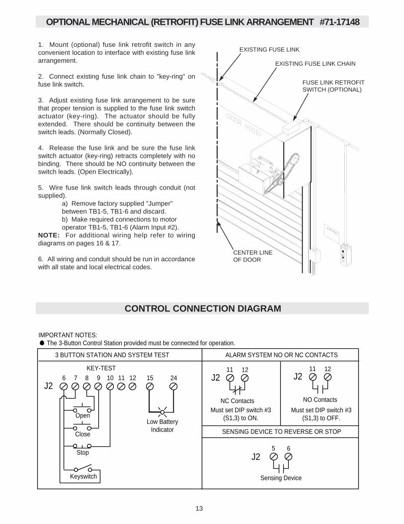
IMPORTANT NOTES: The 3-Button Control Station provided must be connected for operation.
Keyswitch
9 10 11 12
Stop
Close
Open
6 7 8
SENSING DEVICE TO REVERSE OR STOP
3 BUTTON STATION AND SYSTEM TEST ALARM SYSTEM NO OR NC CONTACTS
5 6
Sensing Device
11 12
NC Contacts
11 12
NO Contacts
J2
J2
J2 J2
Must set DIP switch #3(S1,3) to ON.
Must set DIP switch #3(S1,3) to OFF.
15 24
Low BatteryIndicator
CONTROL CONNECTION DIAGRAM
ELECTRONIC FUSE LINK ARRANGEMENT
SINGLE GANGJUNCTION BOX(*2 REQ’D NOTSUPPLIED)
RUN CONDUITTHROUGH WALL
JUNCTIONBOX
CENTER LINEOF DOOR
THERMALSENSOR(*2 SUPPLIED)
OPTIONAL MECHANICAL (RETROFIT) FUSE LINK ARRANGEMENT #71-17148
EXISTING FUSE LINK
EXISTING FUSE LINK CHAIN
FUSE LINK RETROFITSWITCH (OPTIONAL)
CENTER LINEOF DOOR
1. Mount (optional) fuse link retrofit switch in anyconvenient location to interface with existing fuse linkarrangement.
2. Connect existing fuse link chain to "key-ring" onfuse link switch.
3. Adjust existing fuse link arrangement to be surethat proper tension is supplied to the fuse link switchactuator (key-ring). The actuator should be fullyextended. There should be continuity between theswitch leads. (Normally Closed).
4. Release the fuse link and be sure the fuse linkswitch actuator (key-ring) retracts completely with nobinding. There should be NO continuity between theswitch leads. (Open Electrically).
5. Wire fuse link switch leads through conduit (notsupplied).
a) Remove factory supplied "Jumper" between TB1-5, TB1-6 and discard.b) Make required connections to motor operator TB1-5, TB1-6 (Alarm Input #2).
NOTE: For additional wiring help refer to wiringdiagrams on pages 16 & 17.
6. All wiring and conduit should be run in accordancewith all state and local electrical codes.
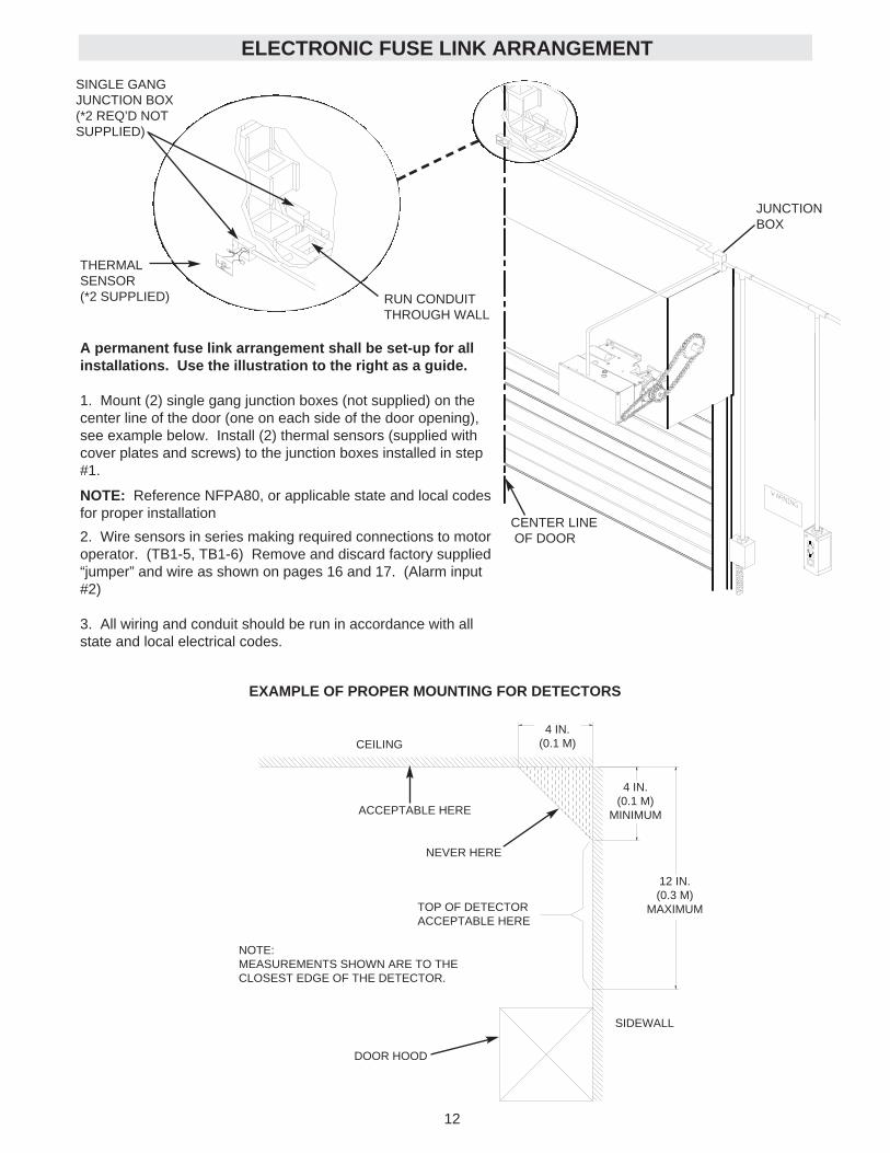
A permanent fuse link arrangement shall be set-up for allinstallations. Use the illustration to the right as a guide.
1. Mount (2) single gang junction boxes (not supplied) on thecenter line of the door (one on each side of the door opening),see example below. Install (2) thermal sensors (supplied withcover plates and screws) to the junction boxes installed in step#1.
NOTE: Reference NFPA80, or applicable state and local codesfor proper installation
2. Wire sensors in series making required connections to motoroperator. (TB1-5, TB1-6) Remove and discard factory supplied“jumper” and wire as shown on pages 16 and 17. (Alarm input#2)
3. All wiring and conduit should be run in accordance with allstate and local electrical codes.
4 IN.(0.1 M)
4 IN.(0.1 M)
MINIMUM
12 IN.(0.3 M)
MAXIMUM
SIDEWALL
CEILING
NOTE:MEASUREMENTS SHOWN ARE TO THECLOSEST EDGE OF THE DETECTOR.
ACCEPTABLE HERE
EXAMPLE OF PROPER MOUNTING FOR DETECTORS
NEVER HERE
TOP OF DETECTORACCEPTABLE HERE
DOOR HOOD
12 13
KEY-TEST
IMPORTANT NOTES: The 3-Button Control Station provided must be connected for operation.
Keyswitch
9 10 11 12
Stop
Close
Open
6 7 8
SENSING DEVICE TO REVERSE OR STOP
3 BUTTON STATION AND SYSTEM TEST ALARM SYSTEM NO OR NC CONTACTS
5 6
Sensing Device
11 12
NC Contacts
11 12
NO Contacts
J2
J2
J2 J2
Must set DIP switch #3(S1,3) to ON.
Must set DIP switch #3(S1,3) to OFF.
15 24
Low BatteryIndicator
CONTROL CONNECTION DIAGRAM
ELECTRONIC FUSE LINK ARRANGEMENT
SINGLE GANGJUNCTION BOX(*2 REQ’D NOTSUPPLIED)
RUN CONDUITTHROUGH WALL
JUNCTIONBOX
CENTER LINEOF DOOR
THERMALSENSOR(*2 SUPPLIED)
OPTIONAL MECHANICAL (RETROFIT) FUSE LINK ARRANGEMENT #71-17148
EXISTING FUSE LINK
EXISTING FUSE LINK CHAIN
FUSE LINK RETROFITSWITCH (OPTIONAL)
CENTER LINEOF DOOR
1. Mount (optional) fuse link retrofit switch in anyconvenient location to interface with existing fuse linkarrangement.
2. Connect existing fuse link chain to "key-ring" onfuse link switch.
3. Adjust existing fuse link arrangement to be surethat proper tension is supplied to the fuse link switchactuator (key-ring). The actuator should be fullyextended. There should be continuity between theswitch leads. (Normally Closed).
4. Release the fuse link and be sure the fuse linkswitch actuator (key-ring) retracts completely with nobinding. There should be NO continuity between theswitch leads. (Open Electrically).
5. Wire fuse link switch leads through conduit (notsupplied).
a) Remove factory supplied "Jumper" between TB1-5, TB1-6 and discard.b) Make required connections to motor operator TB1-5, TB1-6 (Alarm Input #2).
NOTE: For additional wiring help refer to wiringdiagrams on pages 16 & 17.
6. All wiring and conduit should be run in accordancewith all state and local electrical codes.
A permanent fuse link arrangement shall be set-up for allinstallations. Use the illustration to the right as a guide.
1. Mount (2) single gang junction boxes (not supplied) on thecenter line of the door (one on each side of the door opening),see example below. Install (2) thermal sensors (supplied withcover plates and screws) to the junction boxes installed in step#1.
NOTE: Reference NFPA80, or applicable state and local codesfor proper installation
2. Wire sensors in series making required connections to motoroperator. (TB1-5, TB1-6) Remove and discard factory supplied“jumper” and wire as shown on pages 16 and 17. (Alarm input#2)
3. All wiring and conduit should be run in accordance with allstate and local electrical codes.
4 IN.(0.1 M)
4 IN.(0.1 M)
MINIMUM
12 IN.(0.3 M)
MAXIMUM
SIDEWALL
CEILING
NOTE:MEASUREMENTS SHOWN ARE TO THECLOSEST EDGE OF THE DETECTOR.
ACCEPTABLE HERE
EXAMPLE OF PROPER MOUNTING FOR DETECTORS
NEVER HERE
TOP OF DETECTORACCEPTABLE HERE
DOOR HOOD
14 11
1 2 3 4
ON (0 SECOND DELAY)
OFF (10 SECOND DELAY) 1 2 3 4
ON (IR'S ENABLED)
OFF (IR'S DISABLED)
1 2 3 4
ON (FIRE DOOR MODE TYPE I)
OFF (CDO MODE) 1 2 3 4
ON (N.C. ALARM)
OFF (N.O. ALARM)
NOTICE:This equipment has been tested and found tocomply with the limits for a Class A digitaldevice, pursuant to Part 15 of the FCC Rules.These l imits are designed to providereasonable protection against harmfulinterference when the equipment is operatedin a commercial environment. This equipmentgenerates, uses, and can radiate radiofrequency energy and, if not installed and usedin accordance with the instruction manual,may cause harmful interference to radiocommunications. Operation of this equipmentin a residential area is likely to cause harmfulinterference, in which case the user will berequired to correct the interference at his ownexpense.
OPTIONAL CONTROL SETTINGSNOTE: All functions are independent of each other and do not require other control settings to be set at anycertain configuration. For dip switch location refer to illustration on next page. All switches are factory preset to the“OFF” position.
SI-1 ALARM DELAY TO CLOSE - Alarm Delay to Close is the time between when the operator first receives anactive alarm signal and the door starts to close. (In Seconds)
SI-4 INFRARED EYES STATE - The operator will support LiftMaster Infrared Safety Photo Eyes when enabled,and ignore IR inputs when disabled.
TERMINAL BLOCK (J2)
TERMINAL BLOCK (J1)
HEAT SINK
DIP SWITCH (S1)
INSTALLER CONTROL SETTINGSSI-2 FIRE DOOR MODE TYPE I/CDO MODE - The operator only monitors alarm inputs when in the Fire Door
Mode Type I. The operator functions as a standard CDO with B2 wiring when in the CDO mode.
SI-3 ALARM STATE - The operator can accept either a normally open or normally closed dry contact alarm input. DO NOT INDUCE VOLTAGE!
1 2 3 4 5 6 7 8 9 10 11 12
13 14
15
16 17 18 19 20 21 22 23
24
J2L1 L2 L3
J1
GND
POWER IN 115/230V 1PH
(FACTORY JUMPER)
IR'S
REVERSEEDGE
STOP
CLOSE
OPEN
KEY-TEST
C NO
LOW BATTERY INDICATOR
(RD)(WH)
(BR)
ALARM INPUT #1(DRY CONTACT)
N.O. or N.C.
115/230VHOT
115/230VNEUTRAL
T B 1
ELECTRONICFUSE LINK
ALARM INPUT#2(FACTORY JUMPER SUPPLIED)
1 2 3 4 5 6 7 8 9 10
INTERNALTHERMALSENSOR
+24
VD
C
GR
D(1
AM
P M
AX
)
STANDARD POWER & CONTROL CONNECTION DIAGRAMS
LMPLC Board - 115/230V 1PH
1510
CONTROL STATION MOUNTING
POWER WIRING CONNECTIONS
1. Connect power wires to the J1 terminal block locat-ed on the Printed Circuit Board (shown below).
2. Be sure to run all power wires through the conduithole in the electrical box enclosure marked with the labelshown below.
POWER WIRING CONTROL STATION WIRING
CONTROL WIRING CONNECTIONS
1. Connect control wires to the J2 terminal block locat-ed on the Printed Circuit Board (shown below).
2. Be sure to run all control wires through the conduithole in the electrical box enclosure marked with the labelshown below.
3. Apply power to the operator. Press OPEN push buttonand observe direction of door travel and then Press theSTOP button.
If door did not move in the correct direction, check forimproper wiring at the control station or between opera-tor and control station.(See page 19)
GROUND WIRING
1. Connect earth ground to chassis ground screw in theelectrical box enclosure marked with the label shownbelow.
2. Use same conduit entry into the electrical box as thepower wiring.
40-10033B
4 ft.(Approximate)
1. Mount Control Station and Key Test Switchno further than 12” from each other.
2. Mount Control Station and Key Test Switchno further than 12” from the door jamb.(Do not mount directly under the operator)
3. Mount WARNING NOTICE beside or belowthe Control Station.
ControlStation Key Test
Station
(Left Hand Unit Shown)
“UL” WARNING(SEE NOTE)
NOTE:The “UL” Warning label must be read “right side up” from thefloor level. Should your operator mounting cause this label tobe read “upside down”, your accessory kit is supplied with anadditional label. Install the new label so that it will be read“right side up “ from the floor level.
STANDARD POWER & CONTROL CONNECTION DIAGRAMS
LMPLC Board - 230/460V 3PH
1 2 3 4 5 6 7 8 9 10 11 12
13 14
15
16 17 18 19 20 21 22 23
24
J2L1 L2 L3
J1
L1 L2 L3 GND
POWER IN 230/460V 3PH
(FACTORY JUMPER)
IR'S
REVERSEEDGE
STOP
CLOSE
OPEN
KEY-TEST
C NO
LOW BATTERY INDICATOR
(RD)(WH)
(BR)
T B 1
ELECTRONICFUSE LINK
ALARM INPUT#2(FACTORY JUMPER SUPPLIED)
1 2 3 4 5 6 7 8 9 10
INTERNALTHERMALSENSOR
ALARM INPUT #1(DRY CONTACT)
N.O. or N.C.
+24
VD
C
GR
D(1
AM
P M
AX
)
9
INSTALL POWER WIRING & CONTROL STATION
Before installing power wiring or control stations be sure to follow all specifications and warn-ings described below. Failure to do so may result in severe injury to persons and/or damage tooperator.
Do not install any wiring or attempt to run the operator without consulting the wiring diagram.Install the optional Reversing Edge before proceeding with the Control Station installation.
WARNING
CAUTION
WARNING
WARNING
DISCONNECT POWER AT THE FUSE BOX BEFOREPROCEEDING.OPERATOR MUST BE PROPERLY GROUNDED ANDPERMANENTLY WIRED IN ACCORDANCE WITHLOCAL ELECTRICAL CODES. NOTE: THE OPERA-TOR SHOULD BE ON A SEPARATE FUSED LINE OFADEQUATE CAPACITY.ALL ELECTRICAL CONNECTIONS MUST BE MADEBY A QUALIFIED INDIVIDUAL.
WARNING
CAUTION
WARNING
WARNING
TO ENSURE DOOR DESCENT IN AN “ALARM” CON-DITION, AND AVOID DAMAGE TO DOOR AND OPER-ATOR, MAKE ALL DOOR LOCKS INOPERATIVE.SECURE LOCK(S) IN "OPEN" POSITION.
IMPORTANT SAFETY NOTES
WARNING
CAUTION
WARNING
WARNING
ANY MAINTENANCE TO THE OPERATOR OR IN THEAREA NEAR THE OPERATOR MUST NOT BE PER-FORMED UNTIL DISCONNECTING THE ELECTRI-CAL POWER AND LOCKING-OUT THE POWER VIA,THE MAIN DISCONNECT SWITCH. UPON COMPLE-TION OF MAINTENANCE THE AREA MUST BECLEARED AND SECURED, AT THAT TIME THE UNITMAY BE RETURNED TO SERVICE.
WARNING
CAUTION
WARNING
WARNING
INSTALL THE CONTROL STATION WHERE THE DOORIS VISIBLE, BUT AWAY FROM THE DOOR AND ITSHARDWARE. DO NOT INSTALL CONTROL STATIONDIRECTLY BENEATH THE OPERATOR. IF CONTROLSTATION CANNOT BE INSTALLED WHERE DOOR ISVISIBLE, OR IF ANY DEVICE OTHER THAN THE CON-TROL STATION IS USED TO ACTIVATE THE DOOR, ASAFETY DEVICE MUST BE INSTALLED ON THEDOOR, THE MINIMUM ACCEPTABLE DEVICEWOULD BE SAFETY PHOTO EYES, OR A REVERS-ING EDGE INSTALLED ON THE BOTTOM OF THEDOOR. THE BEST PROTECTION IS AFFORDED BYTHE COMBINATION OF THESE TWO DEVICES.
WARNING
CAUTION
WARNING
WARNING
THIS UNIT MUST BE PROPERLY GROUNDED. AGROUND SCREW IS SUPPLIED IN THE ELEC-TRICAL BOX FOR CONNECTION OF THEPOWER SUPPLY GROUND WIRE. FAILURE TOPROPERLY GROUND THIS UNIT COULDRESULT IN ELECTRIC SHOCK AND SERIOUSINJURY.
IMPORTANT
16
(FDC5011,FDC5021,FDC1011,FDC1021)1 PHASE WIRING DIAGRAM 1892
J12
J9
J8 1 2 3 4 5 6 7 8 9 10 11 12
13 14 15 16 17 18 19 20 21 22 23 24
J27 J26
J22
J2L1 L2 L3
J1J29
J20
J28
J25
J7
J6
J23
J24
J21
J16 J19 J5
J13
J15
J14
J18 J17J30J3 J4
S1
RPM BOARD
BRAKECOIL
(WH) (WH/BK)
DC
SAFETY LIMIT SWITCH
(SPARE)LIMIT SWITCH
CLOSELIMIT SWITCH
OPENLIMIT SWITCH
(YE)
(BL)
(RD)
(WH)
(BK)
(RD)
-
+
-
+
12VDCBATTERY
DISCONNECTBATTERY
RESISTOR
CAPACITOR
(BK) (RD)
115V N
GND115V 1PH
POWER IN ONLY
MOTOR
(YE)
(PU)
(GY)
(BL)
T B 1
(FACTORY JUMPER)
(BK) (BK)
INTERNALTHERMALSENSOR
(BK)
(BR)
(BR)
TRANSFORMER
SE
CO
ND
AR
Y
PR
IMA
RY
1
(WH)
(BK)
(BK)
IR'S
REVERSEEDGE
STOP
CLOSE
OPEN
KEY-TEST
C NO
LOW BATTERY INDICATOR
(RD)(WH)
ELECTRONICFUSE LINK
ALARM INPUT#2(FACTORY JUMPER SUPPLIED)
(K6) OPTIONALMOTION STROBE
(K7) OPTIONALFIRE SIREN
(K8) OPTIONALFIRE STROBE
+12 VDC GND
ALARM INPUT#1
(DRY CONTACT ONLY, DO NOT INDUCE VOLTAGE!)
(1 AMP MAX)
OUTPUTS **
+24 VDC
1 AMP MAX
(WH/BK)
(WH)
- +
- +
OVERLOAD
(BK)(BK)
(OR)
(YE)
(BL)
(BR)
(GW
)
(YE
)
(RD
)
(WH
)
Notes:1) See Owner�s Manual for Dip Switch Functions and Programming Procedures2) TO REVERSE MOTOR DIRECTION: REVERSE PURPLE AND GRAY MOTOR WIRES RUNNING TO J6 AND J7 ON THE BOARD.3) TO REVERSE LIMIT SWITCH DIRECTION: MOVE YELLOW AND WHITE WIRES FROM SAFETY LIMIT SWITCH TO SPARE AUXILIARY SWITCH (SEE PAGE 7).4) CONNECTIONS SHOWN IN DOTTED BOUNDARIESARE OPTIONAL USER INTERFACE.** (K7, K8) ARE NORMALLY OPEN DRY CONTACTS WHICH ARE PROGRAMMED TO CLOSE ON ANY ALARM SIGNAL.5) (K6) IS NORMALLY OPEN DRY CONTACT WHICH IS PROGRAMMED TO CLOSE WHEN THE DOOR IS IN MOTION OR INHIBITED DURING A GRAVITY CLOSE.
(RD)
(BL)
10
9
8
7
6
5
4
3
2
1GRD(BK)
(RD)
INTERNAL MOTOR CONNECTIONS
(SHOWN AS LEFT HAND UNIT)
178
The motor operator is manufactured as a standard commercial operator with standard B2wiring functionality. Once installation is completed and all alarm devices are connected,and tested, the installer must then switch the dip switch setting (See page 11). Upon com-pletion of installation, the unit’s functionality should be checked by activating the key teststation (See page 5).If for any reason your unit does not respond as described in this man-ual, check that you have read and followed all installation and operating instructions. If dif-ficulties persist contact the Lift-Master technical hotline.
1-800-528-2806.
Alarm Inputs:Alarm Input #1: Used for electronic alarm devices such as smoke detection devices or similaralarm systems. Devices may be N/O or N/C. Switchable using DIP Switch #3. This alarm will acti-vate a motored closure of the door, and all sensing and control devices will remain active.It is imperative that the alarm signal contact is maintained for a time period greater than the alarmdelay to close setting. I.E. If dip switch #1 is in the “OFF” position (10 seconds) the alarm systemmust supply a “DRY” contact signal to terminals J2-11 & J2-12 for a minimum of 12 seconds.
Alarm Input #2: Used for the thermal sensors (electronic fusible links) or similar systems. (N.C.state only) This alarm condition will activate a motored closure of the door, and all sensingdevices and control stations will be rendered inactive. EXCEPT THE SAFETY EDGE. This alarmwill override any other alarm condition or input.
NOTICE:This equipment has been tested and found to comply with the limits for a Class A digital device, pursuantto Part 15 of the FCC Rules. These limits are designed to provide reasonable protection against harmfulinterference when the equipment is operated in a commercial environment. This equipment generates,uses, and can radiate radio frequency energy and, if not installed and used in accordance with the instruc-tion manual, may cause harmful interference to radio communications. Operation of this equipment in a res-idential area is likely to cause harmful interference, in which case the user will be required to correct theinterference at his own expense.
INSTALLATION MODE
IT IS THE END USERS SOLE RESPONSIBILITY TO CHECKTHAT ALL SYSTEMS ARE INSTALLED AND FUNCTIONAL.THE MOTOR OPERATOR MUST BE SWITCHED TO THE“FIREDOOR MODE TYPE I”TO ENABLE ALL ALARM, ANDWARNING SYSTEMS. DIP SWITCH #2 MUST BE SWITCHEDTO THE “ON” POSITION TO ENABLE THE “FIREDOOR”MODE. FAILURE TO DO SO, COULD RESULT IN LOSS OFLIFE AND PROPERTY.
WARNING
CAUTION
WARNING
WARNING
(FDC5023,FDC5043,FDC1023,FDC1043) 3 PHASE WIRING DIAGRAM 1893
J12
J9
J8 1 2 3 4 5 6 7 8 9 10 11 12
13 14 15 16 17 18 19 20 21 22 23 24
J27 J26
J22
J2L1 L2 L3
J1J29
J20
J28
J25
J7
J6
J23
J24
J21
J16 J19 J5
J13
J15
J14
J18 J17J30J3 J4
S1
RPM BOARD
BRAKECOIL
(WH) (WH/BK)
DC
SAFETY LIMIT SWITCH
CLOSELIMIT SWITCH
OPENLIMIT SWITCH
(YE)
(BL)
(RD)
(WH)
(BK)
(RD)
-
+
-
+
12VDCBATTERY
DISCONNECTBATTERY
RESISTOR
CAPACITOR
(BK) (RD)
(BL)L1 L2 L3 GND
230/460 3PHPOWER IN
(YE)
(PU) (GY)
(1HP & ABOVE)
L1
L2
L3
T1
T2
T3
96
95
(BK)
(BK)
(BK)
OVERLOAD
(BK)
(BK)
(BK)
(BK) (BK)
(FACTORY JUMPER)
(BK) (BK)
INTERNALTHERMALSENSOR
(BK)
MOTOR O/L
(BK)
(RD)
(BR)
(BR)
(BR)
TRANSFORMER
SE
CO
ND
AR
Y
PR
IMA
RY
1
(BR)
(BR)
(WH)
(WH)
(BK)
(BK)
(BK)
(BK)
IR'S
REVERSEEDGE
STOP
CLOSE
OPEN
KEY-TEST
C NO
LOW BATTERY INDICATOR
(RD)(WH)
(K6) OPTIONALMOTION STROBE
(K7) OPTIONALFIRE SIREN
(K8) OPTIONALFIRE STROBE
+12 VDC GND
ALARM INPUT#1
(DRY CONTACT ONLY, DO NOT INDUCE VOLTAGE!)
(1 AMP MAX)
OUTPUTS * *
(WH/BK)
(WH)
- +
- +
SEE NOTE 4*
(GW
)
(YE
)
(RD
)
(WH
)
(BR)
(BK)
(BK)
(BK)
MOTOR
Notes:1) See Owner�s Manual for Dip Switch Functions andProgramming Procedures2) TO REVERSE MOTOR DIRECTION: REVERSEPURPLE AND GRAY MOTOR WIRES RUNNING TO J6 AND J7.
4) CONNECTIONS SHOWN IN DOTTED BOUNDARIESARE OPTIONAL USER INTERFACE. 5) INTERNAL MOTOR OVERLOAD ON MODELS UPTO AND INCLUDING 3/4 HP. EXTERNAL OVERLOAD LOCATED IN ELECTRICAL ENCLOSURE FOR 1 HP MODELS.(K7, K8) ARE NORMALLY OPEN DRY CONTACTS, WHICHARE PROGRAMMED TO CLOSE ON ANY ALARM SIGNAL.6) (K6) IS NORMALLY OPEN DRY CONTACT WHICH IS PROGRAMMED TO CLOSE WHEN THE DOOR IS IN MOTION OR INHIBITED DURING A GRAVITY CLOSE.
*
* *
(RD)
(BL)
ELECTRONICFUSE LINK
ALARM INPUT#2(FACTORY JUMPER SUPPLIED)
3) TO REVERSE LIMIT SWITCH DIRECTION: MOVE YELLOWAND WHITE WIRE FROM SAFETY LIMIT SWITCH TO SPAREAUXILIARY SWITCH (SEE PAGE 7).
(SPARE)LIMIT SWITCH
T B 1
+24 VDC
1 AMP MAX
10
9
8
7
6
5
4
3
2
1GRD
INTERNAL MOTOR CONNECTIONS
* *
(SHOWN AS LEFT HAND UNIT)
7
PHOTO EYES
NOTE: LiftMaster recommends the use of safetyphoto eyes as a non-contact method of entrapmentprotection.
The operator has been manufactured to accept directconnection of LiftMaster Infrared Eyes. See page 11for proper dip switch settings, and pages 14 & 15 forwiring connections. Follow the wiring instructions sup-plied with your LiftMaster Infrared Eyes.
ENTRAPMENT PROTECTION ACCESSORIES
TO AVOID SERIOUS PERSONAL INJURY OR DEATHFROM ELECTROCUTION, DISCONNECT ELECTRICPOWER BEFORE MANUALLY MOVING LIMIT NUTS.
WARNING
CAUTION
WARNING
WARNING
LIMIT SWITCH ADJUSTMENT
MAKE SURE THE LIMIT NUTS ARE POSITIONED BETWEEN THE LIMIT SWITCH ACTUATORS BEFOREPROCEEDING WITH ADJUSTMENTS. BE CERTAIN THAT DIP SWITCH #2 IS IN THE “OFF” POSITION (CDOMODE) BEFORE MAKING ADJUSTMENTS.
If other problems persist, call our toll-free number forassistance - 1-800-528-2806
1. To adjust limit nuts depress retaining plate to allownut to spin freely. After adjustment, release plateand ensure it seats fully in slots of both nuts.
2. To increase door travel, spin nut away from actua-tor. To decrease door travel, spin limit nut towardactuator.
3. Adjust open limit nut so that door will stop in openposition with the bottom of the door even with topof door opening.
4. Repeat Steps 1 and 2 for close cycle. Adjust closelimit nut so that actuator is engaged as door fullyseats at the floor.
Depress Plate CLOSE Limit Switch
SAFETY(Aux. Close) Limit Switch
OPEN Limit Switch
Actuator RPM Board
Rotator Cup
(Shown as LEFTHand Unit)
SPARELimit Switch
18
MAINTENANCE SCHEDULE
* Use SAE 30 Oil (Never use grease or silicone spray).
✔✔ Repeat ALL procedures.
Do not lubricate motor. Motor bearings are lubricated and sealed at the factory.
Inspect and service whenever a malfunction is observed or suspected.
CAUTION: BEFORE SERVICING, ALWAYS DISCONNECT OPERATOR FROM POWER SUPPLY.
Check at the intervals listed in the following chart.
EVERY EVERY EVERYITEM PROCEDURE 3 MONTHS 6 MONTHS 12 MONTHSDrive Chain Check for excessive slack.
Check & adjust as required.Lubricate.* ✔✔
Sprockets Check set screw tightness ✔✔
Fasteners Check & tighten as required ✔✔
Bearings & Shafts Check for wear & lubricate ✔✔
Functionality Activate Key Test switch (see pg. 4) Monthly or as required by regulatory agency
Gearbox - The gearbox on the motor operator is factory sealed, and non vented, and should not require service for thelife of the operator.
Brake Friction Material - The electromagnetic brake on the motor operator is factory adjusted, and should not require service for the life of the operator. Should service be required, the entire unit should be replaced.
Operators require practically no special maintenance other than periodic checking to see that mechanical parts wherenecessary are lubricated and the electrical compartments are clear of dirt.
Service technicians should familiarize themselves with the proper sequence of operation and all related controls. Power tooperator must be disconnected when removing or replacing covers on electrical components, making adjustments, or per-forming maintenance.
1. Check wire connections for tightness and wire insulation for defects of abrasions.2. Check to see that all conduit connections are secure.3. Check wires to safety edge, or infrared safety eyes, if unit is equipped with a safety to reverse feature.4. Inspect operation of brake.5. Inspect gearbox for leaks.6. Inspect roller chain and drive sprockets. Align, lubricate the sprockets, and tighten the set screws.7. Generally inspect the motor mounting, and tighten the fasteners and bracing.8. Verify that all conduit connections are tight and have no exposed wires.9. Inspect the electrical enclosure for debris, arching and moisture. Check for and tighten loose wiring connections.10. Test motor operation through all control stations.11. Check limit switch settings.12. Examine safety edge, coil cord and take-up reel for damage.13. Test the operation of the safety edge.14. Check motor amperage draw for a full open and close cycle. Compare readings to those listed on the motor name-plate.
MOTOR OPERATOR MAINTENANCE
ELECTRIC OR PNEUMATIC EDGE
This operator will also accept various safety edgesoffered by LiftMaster. See pages 14 and 15 for properwiring connections to the operator.
196
1b. Wall MountingThe operator should generally be installed belowthe door shaft, and as close to the door as possi-ble. The optimum distance between the door shaftand operator drive shaft is between 12” - 15”. Referto Figure 2.
OPERATOR MOUNTING
1a. Bracket or Shelf Mounting The operator may be mounted either above orbelow the door shaft. The optimum distancebetween the door shaft and operator drive shaft isbetween 12” - 15”. Refer to Figure 1.
NOTE: The door hood, end plates, and mountingbracket must be rigid, and provide adequate structuralsupport.
1c. Place door sprocket on the door shaft. Do notinsert the key at this time.
2. Wrap drive chain around door sprocket and joinroller chain ends together with master link. (Linkclip should face away from operator.)
3. Raise operator to approximate mounting positionand position chain over operator sprocket.
4. Raise or lower operator until the chain is taut (nottight). Make sure the operator output shaft is par-allel to door shaft and sprockets are aligned. Whenin position, secure the operator to wall or mountingbracket.
5. Install all remaining drive keys and set screws.Apply “Loctite-262” or equivalent locking compound to set screws. (Check that all mountinghardware is tight, and the drive chains are taut.
FIGURE 1 FIGURE 2
Before your operator is installed, be sure the door has been properly aligned and is working smoothly. The opera-tor may be wall mounted or mounted on a bracket or shelf. Refer to the illustration and instructions below that suitsyour application. This motor operator is an integral part of the door system. The motor operator, controls doordescent speed under power outage conditions, therefore the motor operator mounting surface is of major impor-tance. The mounting must provide the following:
- All surfaces should be flat, square, and parallel to the door shaft- The mounting surface must be rigid, and braced off as required- When wall mounting the motor operator, it should be through bolted to the wall- All (8) motor operator mounting points MUST be used- All mounting hardware should be a minimum of grade 5
THIS FIREDOOR CONTROLLER WILL NONOTT CLOSE ABALANCED DOOR IN THE ABSENCE OF ACPOWER.THE DOOR SYSTEM MUST BE ABLE TOGENERATE A MINIMUM BACKDRIVING TORQUE OF100 IN/LBS.,AT THE OPERATOR OUTPUT SHAFT.STICKING OR BINDING DOORS MUST BEREPAIRED. DOORS, DOOR SPRINGS, BRACKETSAND THEIR HARDWARE MAY BE UNDER EXTREMETENSION AND CAN CAUSE SERIOUS PERSONALINJURY. CALL A PROFESSIONAL DOOR SERVICE-MAN TO MOVE OR ADJUST DOOR SPRINGS ORHARDWARE.
WARNING
CAUTION
WARNING
WARNING
Through bolts as required(8 places)
Load spreading plate mounted to wall both sides(supplied by others)
(Right Hand Unit Shown)(Right Hand Unit Shown)
MOTOR OPERATOR TROUBLE SHOOTING GUIDE
Motor does not run when OPEN orCLOSE button is pushed.
Motor runs but door does notmove.
Motor hums but does not run.
Operator runs in wrong directionand limits do not function.
Limit switches do not hold their set-tings.
Door ‘drifts’ when motor shuts off.
Operator does not shut off at fullOPEN or at full CLOSE position.
Operator Functions Erratically
Check circuit breaker, power fuses, safetyswitch; check cause.
Reset; check cause.
Check fuse, check cause.
Close interlocks.
Check drive train for operation
Close & lock off door, remove motor andinspect; check cause.
Check door. Try to operate manually.
Check power supply.
Check power to brake coil.
Check all motor connections.
Interchange any 2 wires in 3O
Adjust chain to proper tension.
Be sure retainer is in slots of BOTH nuts.
Lubricate screw thread. Limit nuts shouldturn freely.
Check brake operation.
Adjust (see above)
Inspect limit chain & sprocket. Adjust chaintension, replace sprocket & chain if required
Operate limit switch manually to determine.
Check line voltage at operator. Low voltage,check cause.Check circuit for high current draws.Eliminate all other units from the circuit.Check ground connections. Check alarmcircuits.Simultaneously depress the “OPEN” &“CLOSE” limit switches, this will reset theoperator’s microprocessor.
Circuit breaker tripped or power fuseblown.
Thermal overload tripped.
Secondary transformer fuse blown.
External interlock open. (if supplied)
Sprocket key missing or drive chain bro-ken.
Intermediate shaft or key damaged.
Door jammed. Drive train jammed.
Dead phase in 3 phase system.
Brake does not release.
Open motor winding.
On 3 phase operators power supply is outof phase.
Drive chain loose, allows chain to jumpsprocket teeth.
Limit nut retainer not engaging slots in limitnuts.
Limit nuts binding on screw threads whichallows them to jump position on retainer.
Brake inoperative or worn.
Limit nuts not adjusted properly.
Sprocket on limit shaft loose or limit drivechain broken.
Defective limit switch
Low line voltage Bad ground“Noise” on electrical lineFaulty alarm wiring
Note: All units are checked for proper rotation at factory. Limit switch adjustmentinstructions in electrical enclosure indicates proper direction of travel for OPEN andCLOSE limit nuts.
SYMPTOM POSSIBLE CAUSE REPAIR
Through bolts as required(8 places)
20
Before beginning any testing, secure the door area, keep unauthorized personnel from entering the area during testing.Be sure ac power is present at the operator, (the green "AC" led will be lighted on the operators control board) and thatthe batteries are connected and fully charged. (the red "DC" led will NOT be lighted on the operators control board)
1. Begin the test with your door at the full "OPEN" position.
2. Make certain dip switch #2 is in the "ON" position "FIREDOOR TYPE I" mode.
3. If your door is equipped with safety photo eyes, make certain dip switch #4 is in the "ON" position.
Note: If 2 minutes total time elapses from the beginning of step #11and the conclusion of step #15, the unit will automat-ically exit the "TEST" mode. To re-enter the "TEST" mode repeat step #4, and continue testing.
4. Turn the wall mounted key test switch to the "TEST" position and hold for a minimum of 6 seconds. This action simu-lates an “ALARM” signal.
5. If dip switch #1 is in the "ON" position, the door should begin to close immediately. If dip switch #1 is in the "OFF"position, the door should begin to close after 10 seconds time has elapsed. (the door will not motor down, it will gravitydescend)
6. Using a "stop-watch" verify that your door is closing between 6" and 24" per second. (i.e.. A 10ft high door shouldclose in a time between 5 and 20 seconds.) Your door should now be fully closed.
7. Open the door by depressing the "OPEN" button on the three button control station.
8. Repeat step #4.
9. When the door is approximately 3 to4 feet from the floor, activate the doors safety edge,(if so equipped) using a crate, skid or alike. Do not introduce any part of your body to the door system during testing. The door shouldreverse to the full open position. Remove the obstruction.
10. The door will begin to close within 1 sec., If dip switch #1 is in the "ON" position. If dip switch # 1 is in the "OFF"position, the door will wait 10 sec. Before beginning to close. The door should fully close to the floor. (the door will notmotor down, it will gravity descend)
11. Repeat steps #7 and #8.
12. When the door is approximately ½ way to the floor, interrupt the safety photo eye beam,(if so equipped) byblocking with a piece of cardboard or alike. Do not introduce any part of your body to the door system during testing. The door should reverse to the full open position.Remove the obstruction.
13. Step #10 repeats.
14. When the door is approximately ½ way to the floor, depress and hold the "STOP" button on the three button controlstation. The door should stop.
15. Release the "STOP" button on the control station. Step #10 repeats.
16. Depress the "OPEN" button on the three button control station. The door should open to the full open position. Theunit is now ready to be returned to service.
DOOR SYSTEM TESTING PROCEDURES
5
REPAIR PARTS KITS – ELECTRICAL BOX
Refer to the parts lists below for replacement kits available for your operator. If optional modifications and/or acces-sories are included with your operator, certain components may be added or removed from these lists. Individualcomponents of each kit may not be available. Please consult a parts and service representative regarding avail-ability of individual components. Refer to page 24 for all repair part ordering information.
K72-16327 LIMIT SHAFT ASSEMBLY KIT
ITEM PART # DESCRIPTION QTY
L1L2L3L4L5L6L7L8
Rotator CupLimit ShaftFlange BearingLimit NutSprocket Washer, SpacerRoll Pin, 1/8” x 1” longE-Ring, 3/8”
11221412
09-1370111-1336112-1002813-1002415-25B22AXX80-1005386-RP04-10087-E-038
K75-16515 LIMIT SWITCH ASSEMBLY KIT
ITEM PART # DESCRIPTION QTY
S1S2S3S4S5S6S7S8S9
Depress PlateNut Plate SwitchBackup PlateSpring, DepressLimit SwitchStandoff, SwitchScrew, #4-40 Pan HeadScrew, #6-32 Pan HeadLock Nut, #6-32
144244822
10-1001310-1255310-1280618-1003623-1004131-1254282-PX04-2082-PX06-1684-LH-06
ELECTRICAL BOX KIT
ITEM PART # DESCRIPTION QTY
E1E2E3E4E5E6E7E8E9
E10E11E12E13E14E15E16E17
E18E19E20
RPM Board KitElectrical Box CoverElectrical BoxBattery PlateElectrical Box Back PlateTransformer (See Variable Chart)Overload (See Variable Chart)Overload Plate (3 Phase Only)Battery, 12VPower Resistor KitContactor (Optional)10 Pole Terminal BlockSensor, ThermostatStandoff Assembly, FDO PCBPCB, LMPLC AssemblyGrommet3/8 x 90 deg. ConnectorAnti-Short BushingLabel, PowerLabel, ControlBridge Rectifier
1111111121
AR1171111221
K74-1651310-1615675-1613510-1613310-1615721-XXXX25-XXXX25-3000K29-NP712K74-1651403-8024K42-11029-1624175-13705K79-13493-128-4875-128-1021928-1022040-1003140-1003229-448
P/N
21-16699
21-16698
25-2006
25-2008
25-2010
25-2015
25-4004-K
25-4002-5K
Item
E6
E7
Description
Transformer, 115/230V 75VA 1 Phase
Transformer, 230/460V 75VA 3 Phase
Overload, 6 Amp
Overload, 8 Amp
Overload, 10 Amp
Overload, 15 Amp
Overload, 3.3 - 5.5 Amp
Overload, 1.6 - 2.5 Amp
FDC
5011
FDC
5021
FDC
5023
FDC
5043
FDC
1011
FDC
1021
FDC
1023
FDC
1043
K77-16669 LABEL KIT
PART # DESCRIPTION QTY
LABEL, GROUNDLABEL, 115V 1 PHASE (115V 1PH ONLY)LABEL, 230V 1 PHASE (230V 1PH ONLY)LABEL, 230V 3 PHASE (230V 3PH ONLY)LABEL, 460V 3 PHASE (460V 3PH ONLY)LABEL, DIRECTIONLABEL, (1A-4A)LABEL, (1-12)LABEL, (13-24)LABEL, WIRING DIAGRAM (1PH ONLY) LABEL, WIRING DIAGRAM (3PH ONLY)LABEL, FDC EBOX UL CAUTIONLABEL, CLASS 2 CIRCUITLABEL, E-BOX COVER SW.SETTIGSLABEL, DOOR OPERATOR WARN. SIGNLABEL, DOOR EDGE CAUTIONLABEL, RESETLABEL, RATING
111111111111211221
132A206040-1023140-1023240-1023340-1023440-1030640-1240740-1607040-1607140-1671540-1671640-1648540-1650940-1660140-600040-6540-79040-9054
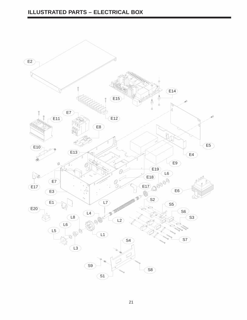
E2
E7
E11
E13
E8
E12
E15
E10
E4
E5
E14
L7
E18
E19
E3
L6
E1
E9
E17E7
L3
L5
L8
L1
L6
L4
L2
S9
S7
S3
S6
E6
S5S2
S8
S4
S1
E17
E20
4
FUNCTIONAL OPERATION CONTINUED
4. Unit has AC power & active alarm condition (ALARM #2 - Fire Sensor, thermal sensor, fuse link.):The unit will activate the optional warning signal (siren/strobe), the door will automatically close after the pre set time delay. (powered down by motor) The time delay is set by means of DIP switch 1.If the door is in the open position and the alarm condition occurs, the door will automatically close under motor operation. In the event the door should meet an obstruction while closing, the door will stop for 2 seconds, then release the door to Gravity Close (controlled descent). After the obstruction has been removed,the door will proceed to the floor.In the event of a failure in motor operation, the operator will gravity close (controlled descent) All control station functions will be rendered inactive in this condition.The safety edge will remain active.
5. Unit has No AC power & No active alarm condition:The Close and Stop buttons of the B2 control station are functional.The door's descending speed is controlled by the integrated braking system.The door will stop if an obstruction is encountered while closing.The Open button is not functional
6. Unit has No AC power & active alarm condition (Alarm #1 or Alarm #2):The unit will activate the OPTIONAL warning signal (siren/strobe), the door will automatically close after thepreset time delay. (controlled by integrated braking system) The time delay is set by means of DIP switch 1.If the door encounters an obstruction while closing , the door will stop on the obstruction, and release the brake after (2) seconds. If the obstruction is then removed the unit will perform a controlled drop of the door. (not powered down by the motor)
7. Activation of the internal Thermal Sensor:Will activate an alarm #2 switch.With AC power present the unit will react as stated in paragraph 4.With No AC power present the unit will react as stated in paragraph 6.
8. Activation of the Key Test Station:Key must be activated for 6 secondsThe unit will activate the OPTIONAL warning signal (siren/strobe), the door will automatically close after the preset time delay. (controlled by integrated braking system) The time delay is set by means of DIP switch 1. (to test the signal devices and the delay time)
The door will close using gravity close mode (Controlled Descent) in order to test the door balance, descent speed, and the moment of the door.All sensing devices and control devices will be active. (In order to test these devices)
(See page 5 for procedures)
21
ILLUSTRATED PARTS – ELECTRICAL BOX
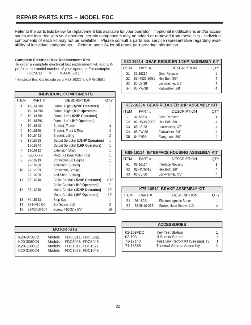
3
GENERAL DESCRIPTION
THIS OPERATOR IS NOT A FIRE ALARM SYSTEM. ITCAN NOT DETECT A FIRE CONDITION.
WARNING
CAUTION
WARNING
WARNING
The Fire Door Controller, FDC, is configurable as a standard CDO or a Fire Door controller (selectable via DIP Switch 2). TheFire Door Mode Type I functions as an integrated fire door control system. It is designed to interface with a normally close (NC)or normally open (NO) dry contact alarm system to control the operation of a fire door. The control station is the standard B2wiring, momentary contact to open, close and stop, plus wiring for sensing device to reverse and auxiliary devices to open andclose with open override.
FIRE DOOR MODE TYPE I FUNCTIONAL OPERATION
1. Battery Management SystemThe batteries are charged, tested, and monitored automatically by the microprocessor based system.The batteries are tested under load every thirty days. If for any reason the batteries fail this load test the on board buzzer will sound for 3 seconds of every minute to indicate that the batteries need to be replaced. If the batteries are not replaced within 45 days (from initial test) the door will automatically close and remain inoperable until the batteries have been replaced. The load test will detect a catastrophic failure such as full loss of batteries when conducted with AC power present (customary situation).When in Battery Backup mode (loss of AC power), the battery voltage is continuously monitored. If for any reason the voltage drops below 22 VDC (this is the minimum operating voltage for the brake controls) the unit will activate the optional warning signal and automatically close the door. The door will remain inoperable until such time that the batteries come back to charge, or they are replaced. Low battery condition will be indicated by the on boardbuzzer sounding 3 seconds out of every minute, and the low battery indicator (located on thekey test station) flashing , until the batteries come to the full charge or are replaced. The batteries must be present and at a working voltage level (21V +) for this function to work.
2. Unit has AC power & no alarm condition:The B2 control station is used to operate the door electrically.Activation of the safety edge while the door is closing will cause the door to reverse to the full open limit.Activation of the safety edge while the door is opening will NOT effect operation, the door willcontinue to the open limit.Activating the key-test switch for at least 6 seconds will put the operator in alarm active mode. (see ACTIVE ALARM section for detail operation of alarm active mode)
3. Unit has AC power & active alarm condition (ALARM #1 - smoke alarm etc.):The unit will activate the OPTIONAL warning signal, the door will automatically close after the preset time delay (powered down by motor). The time delay is set by means of DIPswitch 1.If the door is in the open position and an alarm condition occurs, the door will automatically close under motor operation. In the event the door should meet an obstruction while closing, it will reverse and return to the full open position, and then start the closing cycle (with delay and warning) again. If the obstruction is not removed, the door will close stopping at the lowest possible position holding the brake for 2 seconds, then releasing the door to GRAVITY CLOSE (controlled descent). If after the door has finished the cycling mode andobstruction has been removed, the door will proceed to the floor.In the event of a failure in motor operation, the operator will gravity close (controlled descent).
NOTICE
22
REPAIR PARTS KITS – MODEL FDC
Refer to the parts lists below for replacement kits available for your operator. If optional modifications and/or acces-sories are included with your operator, certain components may be added or removed from these lists. Individualcomponents of each kit may not be available. Please consult a parts and service representative regarding avail-ability of individual components. Refer to page 24 for all repair part ordering information.
K32-16214 GEAR REDUCER 1/2HP ASSEMBLY KIT
ITEM PART # DESCRIPTION QTY
G1G2G3G4
Gear ReducerHex Bolt, 3/8”Lockwasher, 3/8”Flatwasher, 3/8”
1444
32-1621482-HN38-20G585-LS-3885-FW-38
INDIVIDUAL COMPONENTS
ITEM PART # DESCRIPTION QTY
1
2
3456
789
10
11
12
131415
Frame, Right (1/2HP Operators)Frame, Right (1HP Operators)Frame, Left (1/2HP Operators)Frame, Left (1HP Operators)Bracket, FrameBracket, Front & RearBracket, LiftingOutput Sprocket (1/2HP Operators)Output Sprocket (1HP Operators)Extension ShaftMotor Kit (See Motor Kits)Connector, 90 DegreeAnti-Short BushingConnector, StraightAnti-Short BushingBrake Conduit (1/2HP Operators)Brake Conduit (1HP Operators)Motor Conduit (1/2HP Operators)Motor Conduit (1HP Operators)Step KeySet Screw, #10Screw, #10-32 x 5/8”
111142211111111
6.5”8”
13”14”12
16
10-16158R10-16159R10-16158L10-16159L10-1614010-1616010-1648315-1633315-1624411-16112K20-XXXX28-1021928-1022028-1202928-1022028-10218
28-10218
80-1611382-NH10-0482-WX10-10T
K32-16234 GEAR REDUCER 1HP ASSEMBLY KIT
ITEM PART # DESCRIPTION QTY
G1G2G3G4G5
Gear ReducerHex Bolt, 3/8”Lockwasher, 3/8”Flatwasher, 3/8”Flange nut, 3/8”
14444
32-1623482-HN38-20G585-LS-3885-FW-3884-FN38
K08-16114 INTERFACE HOUSING ASSEMBLY KIT
ITEM PART # DESCRIPTION QTY
H1H2H3
Interface HousingHex Bolt, 3/8”Lockwasher, 3/8”
144
08-1611482-HN38-1685-LS-38
K75-16512 BRAKE ASSEMBLY KIT
ITEM PART # DESCRIPTION QTY
B1B2
Electromagnetic BrakeSocket Head Screw, #10
14
36-1622182-SH10-06S
MOTOR KITS
K20-1050C2 Models FDC5011, FDC 5021K20-3050C4 Models FDC5023, FDC5043 K20-1100C2 Models FDC1011, FDC1021K20-3100C4 Models FDC1023, FDC1043
ACCESSORIES
02-109FDC Key Test Station 102-103 3 Button Station 171-17148 Fuse Link Retrofit Kit (See page 13) 174-16685 Thermal Sensor Assembly 2
Complete Electrical Box Replacement Kits To order a complete electrical box replacement kit, add a K-prefix to the model number of your operator. For example:
FDC5011 = K-FDC5011
* Electrical Box Kits include parts K72-16327 and K75-16515
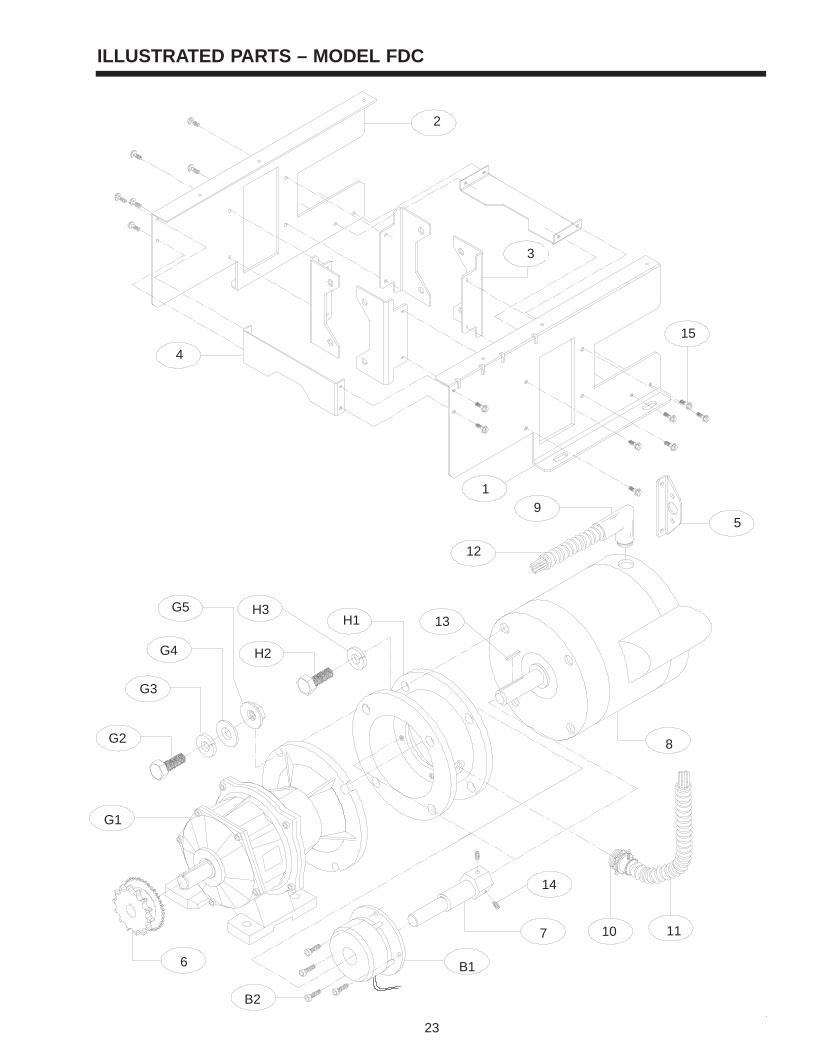
2
SPECIFICATIONS
17.27”
9.00”
A
9.57”
8.50”
MOUNTING DIMENSIONS
1/2HP = 5/16” Mounting Hardware (Typical)1HP = 3/8” Mounting Hardware (Typical)
DRIVE SYSTEMGEAR REDUCERS:....................Helical inline, oil bath
permanently lubricated,non-vented.
CONTINUOUS POWER RATING:1/2 HP: ................................175 ft-lbs/sec1 HP: ................................275 ft-lbs/secRATIO:1/2 Hp: ......................................48.8:1
1 Hp: ......................................49.8:1OUTPUT SPEED 1/2 HP:......................................36 rpm
1 HP: .....................................35 rpmOUTPUT TORQUE 1/2 HP:......................................658 in-lbs.
1 HP: .....................................1345 in-lbs.OUTPUT SHAFT DIA.1/2 HP: .....................................1”
1 HP: .....................................1-1/4”OUTPUT SPROCKET1/2 HP:......................................#50-14T
1 HP: .....................................#60-14TMAX. OVERHUNG LOAD: (1” from output bearing face)1/2 HP:......................................698 Lbs.
1 HP: .....................................1036 Lbs.MAX. BACK DRIVING FORCE: (torque)1/2 HP: .....................................100 in-lbs.
1 HP: .....................................100 in-lbs.Operators available left hand mount. Must be inverted forright hand mount. Limits and motor direction must bereversed when changing handing. (See Pages 16 - 17)
MOTOR
TYPE: ....................................Continuous duty
HORSEPOWER: ...................1/2 HP1 HP
SPEED: .................................1725 RPM
VOLTAGE: .............................115/230 Single phase
230/460 Three Phase
ENCLOSURE:.......................ODP NEMA 56c face mount
ELECTRICAL
TRANSFORMER: ...............1PH: 120/240 VAC 24VAC3PH: 240/480 VAC 24VAC
BATTERY BACKUP: (2) 12VDC 7AH sealed lead
acid batteries
CONTROL STATION: ........NEMA 1 three button station.OPEN/CLOSE/STOP
WIRING TYPE: ...................B2 (Standard)
LIMIT ADJUST: ..................Linear driven, fully adjustablescrew type cams. (70 rev. max @ limit shaft)
DUTY CYCLE: ....................25 Reversing cycles per hour
BRAKE: ..............................24VDC electromagnetic disc
THERMAL SENSORS:.............160 deg.F (Open on rise manual(see page 12) reset, see page 12)
ELECTRICAL ENCLOSURE RATINGS: motors, electrical enclo-sure and control station are rated NEMA1
1/2HP 1HP
ABCDEFGHJK
13.00”21.00”16.93”2.44”3.35”4.53”2.26”6.67”8.25”2.12”
14.38”25.73”16.31”2.93”3.94”5.61”2.80”7.22”7.50”2.51”
ITEMDIMENSIONS
B
D C
4.50”
J
K H
FG
E
WEIGHTS & DIMENSIONS HANGING WEIGHT1/2HP = 80 Lbs.1HP = 100 Lbs.
Operator Center Line
Output SprocketCenter Line
23
ILLUSTRATED PARTS – MODEL FDC
2
12
1
3
4
9
10
H2
H1H3
G4
11
8
5
G3
G2
6 B1
B2
G1
7
13
14
15
G5
OWNER’S MANUALMODEL FDC
ADVANCED LOGICINDUSTRIAL DUTY FIRE DOOR OPERATOR
US PATENT NO. 6,014,307
LMPLC CONTROL
C O N T R O L W I R E D
LMPLC
NOT FOR RESIDENTIAL USE
LISTED DOOR OPERATOR
41B6Serial #
(located on electrical box cover)
Installation Date
Wiring Type
2 YEAR WARRANTY
c 2002, The Chamberlain Group, Inc.
All rights ReservedLISTED DOOR OPERATOR
41B6
01-16219H
HOW TO ORDER REPAIR PARTS
INSTALLATION AND SERVICE INFORMATION AVAILABLEFROM THE TECHNICAL PARTS AND SERVICE CENTER
ARE AVAILABLE 6 DAYS A WEEKCALL OUR TOLL FREE NUMBER - 1-800-528-2806
HOURS 7:00 TO 3:30 p.m. (Mountain Std. Time)MONDAY Through SATURDAY
WHEN ORDERING REPAIR PARTSPLEASE SUPPLY THE FOLLOWING INFORMATION:PART NUMBER DESCRIPTION MODEL NUMBER
ADDRESS ORDER TO:THE CHAMBERLAIN GROUP, INC.
Electronic Parts & Service Dept.2301 N. Forbes Blvd., Suite 104
Tucson, AZ 85745