FIPS 140-2 Non-Proprietary Security Policy · 2.9.2 Conditional Self-Tests ... was prepared as part...
24
Hewlett-Packard Enterprise Development LP HPE P-Class Smart Array Gen9 RAID Controllers Hardware Models: P244br, P246br, P440, P441, and P741m Firmware Version: 2.52 FIPS 140-2 Non-Proprietary Security Policy FIPS Security Level: 1 Document Version: 0.6 Prepared for: Prepared by: Hewlett-Packard Enterprise Development LP Corsec Security, Inc. 11445 Compaq Center Dr. W. 13291 Park Center Road, Suite 460 Houston, TX 77070 Herndon, VA 20171 United States of America United States of America Phone: +1 281 370 0670 Phone: +1 703 267 6050 www.hpe.com www.corsec.com
Transcript of FIPS 140-2 Non-Proprietary Security Policy · 2.9.2 Conditional Self-Tests ... was prepared as part...

Hewlett-Packard Enterprise Development LP HPE P-Class Smart Array Gen9 RAID Controllers Hardware Models: P244br, P246br, P440, P441, and P741m Firmware Version: 2.52
FIPS 140-2 Non-Proprietary Security Policy
FIPS Security Level: 1 Document Version: 0.6
Prepared for: Prepared by:
Hewlett-Packard Enterprise Development LP
Corsec Security, Inc.
11445 Compaq Center Dr. W. 13291 Park Center Road, Suite 460 Houston, TX 77070 Herndon, VA 20171 United States of America United States of America Phone: +1 281 370 0670 Phone: +1 703 267 6050 www.hpe.com www.corsec.com
FIPS 140-2 Non-Proprietary Security Policy, Version 0.6 June 26, 2018
HPE P-Class Smart Array Gen9 RAID Controllers
©2018 Hewlett-Packard Enterprise Development LP This document may be freely reproduced and distributed whole and intact including this copyright notice.
Page 2 of 24
Table of Contents
1. Introduction .........................................................................................................................................4 1.1 Purpose .................................................................................................................................................4 1.2 References .............................................................................................................................................4 1.3 Document Organization ........................................................................................................................4
2. Smart Array Controllers .........................................................................................................................5 2.1 Overview ...............................................................................................................................................5 2.2 Module Specification .............................................................................................................................8 2.3 Module Interfaces .............................................................................................................................. 10 2.4 Roles, Services, and Authentication ................................................................................................... 11 2.5 Physical Security ................................................................................................................................. 14 2.6 Operational Environment ................................................................................................................... 14 2.7 Cryptographic Key Management ....................................................................................................... 14 2.8 EMI / EMC ........................................................................................................................................... 16 2.9 Self-Tests ............................................................................................................................................ 16
2.9.1 Power-Up Self-Tests .............................................................................................................. 16 2.9.2 Conditional Self-Tests ............................................................................................................ 16 2.9.3 Critical Functions Self-Tests .................................................................................................. 16
2.10 Mitigation of Other Attacks................................................................................................................ 17
3. Secure Operation ................................................................................................................................ 18 3.1 Initial Setup ........................................................................................................................................ 18
3.1.1 Initial Setup ........................................................................................................................... 18 3.2 Secure Management .......................................................................................................................... 20
3.2.1 Management ......................................................................................................................... 20 3.2.2 Monitoring Status.................................................................................................................. 20 3.2.3 Zeroization............................................................................................................................. 20
3.3 User Guidance .................................................................................................................................... 20 3.4 Additional Usage Policies .................................................................................................................. 20 3.5 Non-FIPS-Approved Mode ................................................................................................................. 21
4. Acronyms ........................................................................................................................................... 22
List of Tables
Table 1 – Security Level per FIPS 140-2 Section .........................................................................................................8 Table 2 – Controller Form Factor/Processor Configurations......................................................................................9 Table 3 – FIPS-Approved Algorithm Implementations ............................................................................................ 10 Table 4 – FIPS 140-2 Logical Interface Mappings .................................................................................................... 11 Table 5 – Operator Services..................................................................................................................................... 12 Table 6 – Unallocated Services ................................................................................................................................ 13

FIPS 140-2 Non-Proprietary Security Policy, Version 0.6 June 26, 2018
HPE P-Class Smart Array Gen9 RAID Controllers
©2018 Hewlett-Packard Enterprise Development LP This document may be freely reproduced and distributed whole and intact including this copyright notice.
Page 3 of 24
Table 7 – Authentication Mechanism ..................................................................................................................... 14 Table 8 – List of Cryptographic Keys, Cryptographic Key Components, and CSPs .................................................. 15 Table 9 – Acronyms ................................................................................................................................................. 22
List of Figures
Figure 1 – P244br Controller ......................................................................................................................................6 Figure 2 – P246br Controller ......................................................................................................................................6 Figure 3 – P440 Controller ..........................................................................................................................................6 Figure 4 – P441 Controller ..........................................................................................................................................7 Figure 5 – P741m Controller .......................................................................................................................................7 Figure 6 – Smart Array Controllers Block Diagram .....................................................................................................9
FIPS 140-2 Non-Proprietary Security Policy, Version 0.6 June 26, 2018
HPE P-Class Smart Array Gen9 RAID Controllers
©2018 Hewlett-Packard Enterprise Development LP This document may be freely reproduced and distributed whole and intact including this copyright notice.
Page 4 of 24
1. Introduction
1.1 Purpose This is a non-proprietary Cryptographic Module Security Policy for the HPE P-Class Smart Array Gen9 RAID Controllers from Hewlett-Packard Enterprise Development LP (HPE). This Security Policy describes how the HPE P-Class Smart Array Gen9 RAID Controllers meet the security requirements of Federal Information Processing Standards (FIPS) Publication 140-2, which details the U.S. and Canadian Government requirements for cryptographic modules. More information about the FIPS 140-2 standard and validation program is available on the National Institute of Standards and Technology (NIST) and the Communications Security Establishment (CSE) Cryptographic Module Validation Program (CMVP) website at http://csrc.nist.gov/groups/STM/cmvp. This document also describes how to run the module in a secure FIPS-Approved mode of operation. This policy was prepared as part of the Level 1 FIPS 140-2 validation of the module. The HPE P-Class Smart Array Gen9 RAID Controllers are referred to in this document as “Smart Array Controllers”, “controllers”, or “modules”.
1.2 References This document deals only with operations and capabilities of the modules in the technical terms of a FIPS 140-2 cryptographic module security policy. More information is available on the modules from the following sources:
• The HPE website (www.hpe.com) contains information on the full line of products from HPE.
• The CMVP website (http://csrc.nist.gov/groups/STM/cmvp/documents/140-1/140val-all.htm) contains contact information for individuals to answer technical or sales-related questions for the module.
1.3 Document Organization The Security Policy document is organized into two (2) primary sections. Section 2 provides an overview of the validated modules. This includes a general description of the capabilities and the use of cryptography, as well as a presentation of the validation level achieved in each applicable functional area of the FIPS standard. It also provides high-level descriptions of how the modules meet FIPS requirements in each functional area. Section 3 documents the guidance needed for the secure use of the module, including initial setup instructions and management methods and policies.
FIPS 140-2 Non-Proprietary Security Policy, Version 0.6 June 26, 2018
HPE P-Class Smart Array Gen9 RAID Controllers
©2018 Hewlett-Packard Enterprise Development LP This document may be freely reproduced and distributed whole and intact including this copyright notice.
Page 5 of 24
2. Smart Array Controllers
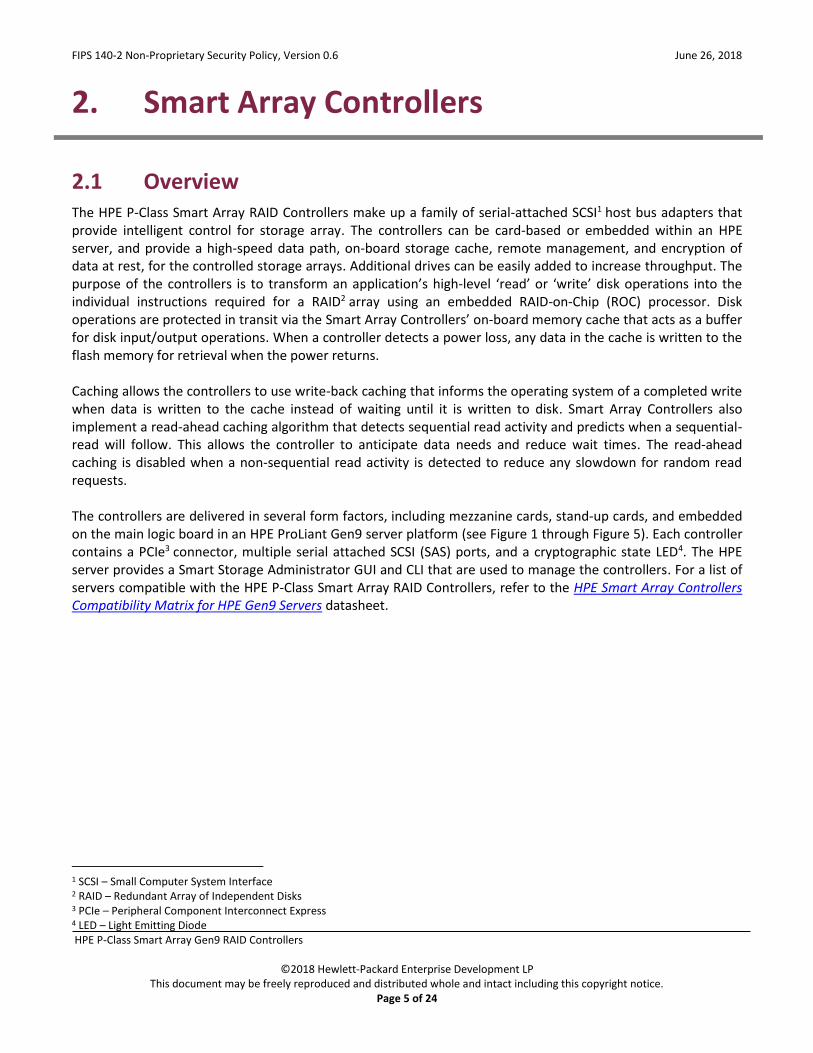
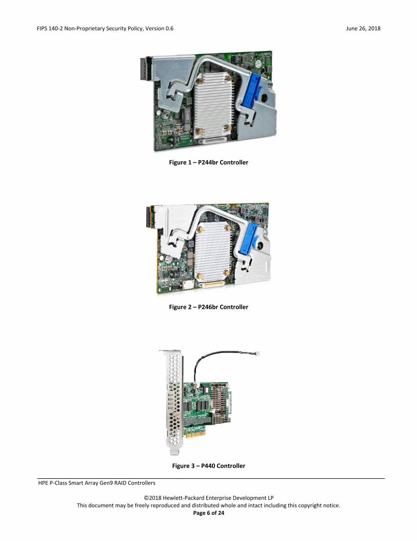
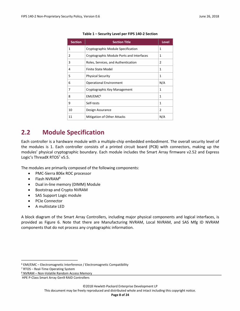
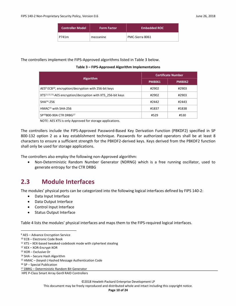
2.1 Overview The HPE P-Class Smart Array RAID Controllers make up a family of serial-attached SCSI1 host bus adapters that provide intelligent control for storage array. The controllers can be card-based or embedded within an HPE server, and provide a high-speed data path, on-board storage cache, remote management, and encryption of data at rest, for the controlled storage arrays. Additional drives can be easily added to increase throughput. The purpose of the controllers is to transform an application’s high-level ‘read’ or ‘write’ disk operations into the individual instructions required for a RAID2 array using an embedded RAID-on-Chip (ROC) processor. Disk operations are protected in transit via the Smart Array Controllers’ on-board memory cache that acts as a buffer for disk input/output operations. When a controller detects a power loss, any data in the cache is written to the flash memory for retrieval when the power returns. Caching allows the controllers to use write-back caching that informs the operating system of a completed write when data is written to the cache instead of waiting until it is written to disk. Smart Array Controllers also implement a read-ahead caching algorithm that detects sequential read activity and predicts when a sequential-read will follow. This allows the controller to anticipate data needs and reduce wait times. The read-ahead caching is disabled when a non-sequential read activity is detected to reduce any slowdown for random read requests. The controllers are delivered in several form factors, including mezzanine cards, stand-up cards, and embedded on the main logic board in an HPE ProLiant Gen9 server platform (see Figure 1 through Figure 5). Each controller contains a PCIe3 connector, multiple serial attached SCSI (SAS) ports, and a cryptographic state LED4. The HPE server provides a Smart Storage Administrator GUI and CLI that are used to manage the controllers. For a list of servers compatible with the HPE P-Class Smart Array RAID Controllers, refer to the HPE Smart Array Controllers Compatibility Matrix for HPE Gen9 Servers datasheet.
1 SCSI – Small Computer System Interface 2 RAID – Redundant Array of Independent Disks 3 PCIe – Peripheral Component Interconnect Express 4 LED – Light Emitting Diode
FIPS 140-2 Non-Proprietary Security Policy, Version 0.6 June 26, 2018
HPE P-Class Smart Array Gen9 RAID Controllers
©2018 Hewlett-Packard Enterprise Development LP This document may be freely reproduced and distributed whole and intact including this copyright notice.
Page 6 of 24
Figure 1 – P244br Controller
Figure 2 – P246br Controller
Figure 3 – P440 Controller

FIPS 140-2 Non-Proprietary Security Policy, Version 0.6 June 26, 2018
HPE P-Class Smart Array Gen9 RAID Controllers
©2018 Hewlett-Packard Enterprise Development LP This document may be freely reproduced and distributed whole and intact including this copyright notice.
Page 7 of 24
Figure 4 – P441 Controller
Figure 5 – P741m Controller
The Smart Array Controllers provide encryption for data at rest. Each controller includes a PMC-Sierra ASIC5 that generates the keys to be used for encryption. The controllers utilize a front-end strategy to encrypt all host data. Data from the host first enters the encryption engine before moving to the cache module and then to the RAID storage. The controllers also include a key management framework for managing disk encryption keys. Each logical drive in the storage array is encrypted with its own disk encryption key. These keys are then encrypted with a second key for storage on the drive. Smart Array stores keys in encrypted form in multiple locations to provide data storage that is secure and mobile. The Smart Array Controllers are validated at the FIPS 140-2 section levels shown in Table 1.
5 ASIC – Application-Specific Integrated Circuit
FIPS 140-2 Non-Proprietary Security Policy, Version 0.6 June 26, 2018
HPE P-Class Smart Array Gen9 RAID Controllers
©2018 Hewlett-Packard Enterprise Development LP This document may be freely reproduced and distributed whole and intact including this copyright notice.
Page 8 of 24
Table 1 – Security Level per FIPS 140-2 Section
Section Section Title Level
1 Cryptographic Module Specification 1
2 Cryptographic Module Ports and Interfaces 1
3 Roles, Services, and Authentication 2
4 Finite State Model 1
5 Physical Security 1
6 Operational Environment N/A
7 Cryptographic Key Management 1
8 EMI/EMC6 1
9 Self-tests 1
10 Design Assurance 2
11 Mitigation of Other Attacks N/A
2.2 Module Specification Each controller is a hardware module with a multiple-chip embedded embodiment. The overall security level of the modules is 1. Each controller consists of a printed circuit board (PCB) with connectors, making up the modules’ physical cryptographic boundary. Each module includes the Smart Array firmware v2.52 and Express Logic’s ThreadX RTOS7 v5.5. The modules are primarily composed of the following components:
• PMC-Sierra 806x ROC processor
• Flash NVRAM8
• Dual in-line memory (DIMM) Module
• Bootstrap and Crypto NVRAM
• SAS Support Logic module
• PCIe Connector
• A multistate LED A block diagram of the Smart Array Controllers, including major physical components and logical interfaces, is provided as Figure 6. Note that there are Manufacturing NVRAM, Local NVRAM, and SAS Mfg ID NVRAM components that do not process any cryptographic information.
6 EMI/EMC – Electromagnetic Interference / Electromagnetic Compatibility 7 RTOS – Real-Time Operating System 8 NVRAM – Non-Volatile Random Access Memory

FIPS 140-2 Non-Proprietary Security Policy, Version 0.6 June 26, 2018
HPE P-Class Smart Array Gen9 RAID Controllers
©2018 Hewlett-Packard Enterprise Development LP This document may be freely reproduced and distributed whole and intact including this copyright notice.
Page 9 of 24
Flash
NVRAM
DIMM
Module
Non-cryptographic
components
Plaintext data
Encrypted data
Control input
Status output
Crypto boundary
LED
KEY:
Operational
Power Supply
Encryption
NVRAM
Bootstrap
NVRAM
SAS ports
SAS
Support
Logic
Serial
port
Local
NVRAM
CLK
75MHz
SAS
Mfg ID
PCIe Connector
PMC 806x
Manufacturing
NVRAM
SAS – Serial Attached SCSI
NVRAM – Non-Volatile Random Access Memory
PCIe – Peripheral Component Interconnect Express
DIMM – Dual In-Line Memory Module
LED – Light Emitting Diode
Figure 6 – Smart Array Controllers Block Diagram
These components appear in a variety of physical layouts depending on the module form factor. Table 2 below provides details regarding the form factor and embedded ROC for each controller model.
Table 2 – Controller Form Factor/Processor Configurations
Controller Model Form Factor Embedded ROC
P244br embedded PMC-Sierra 8062
P246br embedded PMC-Sierra 8062
P440 stand-up card PMC-Sierra 8061
P441 stand-up card PMC-Sierra 8061
FIPS 140-2 Non-Proprietary Security Policy, Version 0.6 June 26, 2018
HPE P-Class Smart Array Gen9 RAID Controllers
©2018 Hewlett-Packard Enterprise Development LP This document may be freely reproduced and distributed whole and intact including this copyright notice.
Page 10 of 24
Controller Model Form Factor Embedded ROC
P741m mezzanine PMC-Sierra 8061
The controllers implement the FIPS-Approved algorithms listed in Table 3 below.
Table 3 – FIPS-Approved Algorithm Implementations
Algorithm Certificate Number
PM8061 PM8062
AES9 ECB10, encryption/decryption with 256-bit keys #2902 #2903
XTS11,12,13-AES encryption/decryption with XTS_256-bit keys #2902 #2903
SHA14-256 #2442 #2443
HMAC15 with SHA-256 #1837 #1838
SP16800-90A CTR DRBG17 #529 #530
NOTE: AES XTS is only Approved for storage applications.
The controllers include the FIPS-Approved Password-Based Key Derivation Function (PBKDF2) specified in SP 800-132 option 2 as a key establishment technique. Passwords for authorized operators shall be at least 8 characters to ensure a sufficient strength for the PBKDF2-derived keys. Keys derived from the PBKDF2 function shall only be used for storage applications. The controllers also employ the following non-Approved algorithm:
• Non-Deterministic Random Number Generator (NDRNG) which is a free running oscillator, used to generate entropy for the CTR DRBG
2.3 Module Interfaces The modules’ physical ports can be categorized into the following logical interfaces defined by FIPS 140-2:
• Data Input Interface
• Data Output Interface
• Control Input Interface
• Status Output Interface Table 4 lists the modules’ physical interfaces and maps them to the FIPS-required logical interfaces.
9 AES – Advance Encryption Service 10 ECB – Electronic Code Book 11 XTS – XEX-based tweaked-codebook mode with ciphertext stealing 12 XEX – XOR-Encrypt-XOR 13 XOR – Exclusive Or 14 SHA – Secure Hash Algorithm 15 HMAC – (keyed-) Hashed Message Authentication Code 16 SP – Special Publication 17 DBRG – Deterministic Random Bit Generator
FIPS 140-2 Non-Proprietary Security Policy, Version 0.6 June 26, 2018
HPE P-Class Smart Array Gen9 RAID Controllers
©2018 Hewlett-Packard Enterprise Development LP This document may be freely reproduced and distributed whole and intact including this copyright notice.
Page 11 of 24
Table 4 – FIPS 140-2 Logical Interface Mappings
Device Physical Port/Interface Quantity FIPS 140-2 Logical Interface
P244br
PCIe Connector 1 Data Input, Data Output, Control Input, Status Output
SAS port(s) 2 x 1 Data Input, Data Output
Multistate LED 1 Status Output
Serial port 1 Status Output
P246br
PCIe Connector 1 Data Input, Data Output, Control Input, Status Output
SAS port(s) 4 x 1 Data Input, Data Output
Multistate LED 1 Status Output
Serial port 1 Status Output
P440
PCIe Connector 1 Data Input, Data Output, Control Input, Status Output
SAS port(s) 1 x 8 Data Input, Data Output
Multistate LED 1 Status Output
Serial port 1 Status Output
P441
PCIe Connector 1 Data Input, Data Output, Control Input, Status Output
SAS port(s) 2 x 4
Data Input, Data Output
Multistate LED 1 Status Output
Serial port 1 Status Output
P741m
PCIe Connector 1 Data Input, Data Output, Control Input, Status Output
SAS port(s) 4 x 2 Data Input, Data Output
Multistate LED 1 Status Output
Serial port 1 Status Output
2.4 Roles, Services, and Authentication There are two roles that operators may assume: a Crypto Officer (CO) role and a User role. Roles are assumed explicitly by means of a username and password. The module does not support multiple concurrent operators. Please note that the keys and Critical Security Parameters (CSPs) listed in the table indicate the type of access required using the following notation:
• R – Read: The CSP is read.
• W – Write: The CSP is established, generated, modified, or zeroized.
• X – Execute: The CSP is used within an Approved or Allowed security function or authentication mechanism.
Operator services are listed and described in Table 5. Access to these services requires the operator to assume one of the supported authorized roles.

FIPS 140-2 Non-Proprietary Security Policy, Version 0.6 June 26, 2018
HPE P-Class Smart Array Gen9 RAID Controllers
©2018 Hewlett-Packard Enterprise Development LP This document may be freely reproduced and distributed whole and intact including this copyright notice.
Page 12 of 24
Table 5 – Operator Services
Service18 Operator
Description Input Output CSP and Type of Access CO User
Initialize module x Configure the module for operation
Command and password
Command response and status output
CO password – X
Set/reset Local Master Key
x Set or reset Local Master Key
Command and password
Command response and status output
Local Master Key – W CO password – X
Enable encryption
x Turn encryption on for the controller as part of initialization
Command and password
Command response and status output
DEK19 – R, X CO password – X
Enable User role x Create User and assign a password
Command and password
Command response and status output
User password – W CO password – X
Set key management mode
x Select key management mode on GUI
Command and password
Command response and status output
Local Master Key – R, W, X CO password – X
Perform data transformations
x x Modify the distribution or contents of one or more logical drives, including:
• adding/removing physical drives
• deleting logical drives
• adding encrypted logical drives
• moving logical drives from one array to another
• changing a logical drive’s RAID level or stripe size
• optimizing alignment for logical drives
• encrypting data destined for an encrypted logical drive
Command Command response and status output
DEK – R, X
Rekey x Rekey DEK Command and parameters
Command response DEK – R, W CO password – X
Set password x x Change operator password
Command Command response and status output
CO password – W User password – W
Lock firmware x x Lock firmware so that it cannot be flashed
Command Command response CO password – X User password – X
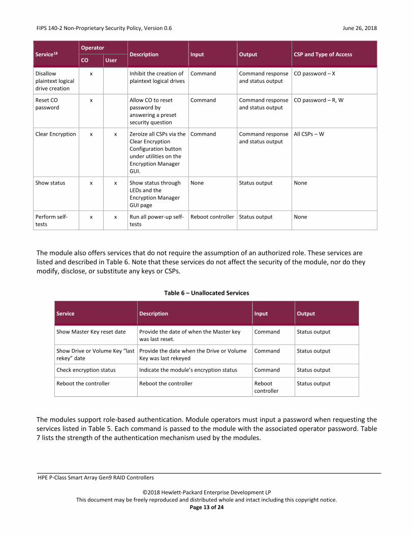
18 Note that the “Show status” and “Perform self-tests” services are allocated to the Crypto Officer and User roles. However, module operators are not required to assume an authorized role to perform these services, as these services do not affect the security of the module (refer to FIPS Implementation Guidance 5.2 for details). 19 DEK – Data Encryption Key
FIPS 140-2 Non-Proprietary Security Policy, Version 0.6 June 26, 2018
HPE P-Class Smart Array Gen9 RAID Controllers
©2018 Hewlett-Packard Enterprise Development LP This document may be freely reproduced and distributed whole and intact including this copyright notice.
Page 13 of 24
Service18 Operator
Description Input Output CSP and Type of Access CO User
Disallow plaintext logical drive creation
x Inhibit the creation of plaintext logical drives
Command Command response and status output
CO password – X
Reset CO password
x Allow CO to reset password by answering a preset security question
Command Command response and status output
CO password – R, W
Clear Encryption x x Zeroize all CSPs via the Clear Encryption Configuration button under utilities on the Encryption Manager GUI.
Command Command response and status output
All CSPs – W
Show status x x Show status through LEDs and the Encryption Manager GUI page
None Status output None
Perform self-tests
x x Run all power-up self-tests
Reboot controller Status output None
The module also offers services that do not require the assumption of an authorized role. These services are listed and described in Table 6. Note that these services do not affect the security of the module, nor do they modify, disclose, or substitute any keys or CSPs.
Table 6 – Unallocated Services
Service Description Input Output
Show Master Key reset date Provide the date of when the Master key was last reset.
Command Status output
Show Drive or Volume Key “last rekey” date
Provide the date when the Drive or Volume Key was last rekeyed
Command Status output
Check encryption status Indicate the module’s encryption status Command Status output
Reboot the controller Reboot the controller Reboot controller
Status output
The modules support role-based authentication. Module operators must input a password when requesting the services listed in Table 5. Each command is passed to the module with the associated operator password. Table 7 lists the strength of the authentication mechanism used by the modules.

FIPS 140-2 Non-Proprietary Security Policy, Version 0.6 June 26, 2018
HPE P-Class Smart Array Gen9 RAID Controllers
©2018 Hewlett-Packard Enterprise Development LP This document may be freely reproduced and distributed whole and intact including this copyright notice.
Page 14 of 24
Table 7 – Authentication Mechanism
Authentication Type Strength CO/User Password The minimum length of the password is 8 characters, with 94 different case-sensitive
alphanumeric characters and symbols possible for usage. The module imposes character type and case restrictions so that the password must have a number, upper case letter, lower case letter, and special character. The remaining 4 characters could be any of the 94 choices. The chance of a random attempt falsely succeeding is
= 1 : (10*26*26*32*944), or 1 : 16,889,161,502,720
which is less than 1:1,000,000 as required by FIPS 140-2.
In addition, the module imposes a restriction on the number of passwords that can be entered into the module. After ten failures, there is a 15-minute delay before another attempt can be made. So, in effect and at most, 10 passwords can be tried per 15 minutes. The probability that a random attempt will succeed or a false acceptance will occur in one minute is
= 1 : (16,889,161,502,720 possible passwords / 10 passwords per minute)
= 1 : 16.8891 x 10¹¹
which is less than 1:100,000 as required by FIPS 140-2.
2.5 Physical Security The Smart Array Controllers are multiple-chip embedded cryptographic modules. Each module consists of production-grade components that include standard passivation techniques.
2.6 Operational Environment The modules employ a non-modifiable operating environment. The modules’ firmware (Firmware version: 2.52) is executed by the module’s PMC processor. The modules do not provide a general-purpose operating system to module operators.
2.7 Cryptographic Key Management The controllers offer two key management modes: local or remote. In local mode, the modules generate and store all of its keys. For Approved mode operation, the modules shall be configured to operate in local key management mode. Table 8 below describes the keys and CSPs supported by the modules.

FIPS 140-2 Non-Proprietary Security Policy, Version 0.6 June 26, 2018
HPE P-Class Smart Array Gen9 RAID Controllers
©2018 Hewlett-Packard Enterprise Development LP This document may be freely reproduced and distributed whole and intact including this copyright notice.
Page 15 of 24
Table 8 – List of Cryptographic Keys, Cryptographic Key Components, and CSPs
CSP CSP Type Generation / Input Output Storage Zeroization Use
DEK 256-bit AES-XTS key Generated internally Never exits the module
Stored in plaintext in volatile DIMM module
Reboot Delete logical drive
Encryption and decryption of logical drives
Crypto Officer Password
8 – 16 character password
Entered electronically Never exits the module
Stored in encrypted form in NVRAM Stored in plaintext in volatile DIMM module
Return to factory reset Reboot
Authenticate Crypto Officer
User Password 8 – 16 character password
Entered electronically Never exits the module
Stored in encrypted form in NVRAM Stored in plaintext in volatile DIMM module
Return to factory reset Reboot
Authenticate User
CTR_DRBG seed 384-bit random value Generated internally Never exits the module
Stored temporarily in volatile DIMM module in plaintext
Automatically upon completion of CTR_DRBG seed operation
Used to seed the CTR_DRBG
CTR_DRBG entropy input
256-bit random value Generated internally Never exits the module
Stored temporarily in volatile DIMM module in plaintext
Automatically upon completion of CTR_DRBG seed operation
Used in the process of generating a random number
Local Master Key
256-bit AES key Derived as per SP 800-132 using PBKDF2 and HMAC-SHA-256
Never exits the module
Stored in plaintext in NVRAM
Return to factory reset.
Encryption and decryption of DEKs

FIPS 140-2 Non-Proprietary Security Policy, Version 0.6 June 26, 2018
HPE P-Class Smart Array Gen9 RAID Controllers
©2018 Hewlett-Packard Enterprise Development LP This document may be freely reproduced and distributed whole and intact including this copyright notice.
Page 16 of 24
2.8 EMI / EMC The Smart Array Controllers were tested and found conformant to the EMI/EMC requirements specified by 47 Code of Federal Regulations, Part 15, Subpart B, Unintentional Radiators, Digital Devices, Class A (business use).
2.9 Self-Tests Cryptographic self-tests are performed by each module when first powered up as well as when a random number is generated. The following sections list the self-tests performed by the modules, their expected error status, and error resolutions.
2.9.1 Power-Up Self-Tests The HPE P-Class Smart Array RAID Controllers perform the following self-tests at power-up:
• Firmware integrity check – a 32-bit Cyclic Redundancy Check (CRC)
• Known Answer Tests (KATs) o AES-ECB encrypt KAT o AES-ECB decrypt KAT o AES-XTS encrypt KAT o AES-XTS decrypt KAT o SHA-256 KAT o HMAC SHA-256 KAT o CTR DRBG KAT
If any of these self-test fail, encrypted drives are taken offline and the modules enter a critical error state. An error message of the failure is logged.
2.9.2 Conditional Self-Tests The HPE P-Class Smart Array RAID Controllers perform the following conditional self-tests:
• Continuous RNG for NDRNG
• Continuous RNG for CTR DRBG
If any of the RNG conditional self-tests fail, the modules enter a critical error and all cryptographic operations are halted. An error message of each failure is logged.
2.9.3 Critical Functions Self-Tests The DRBG Instantiate, Generate, and Reseed Tests, which are described in SP 800-90A, are performed by the modules at start-up or anytime the DRBG is instantiated. These tests are critical function self-tests. A failure of any of these tests results in a critical error for the DRBG, requiring that the modules be replaced. When the DRBG is in error, no new keys can be generated.

FIPS 140-2 Non-Proprietary Security Policy, Version 0.6 June 26, 2018
HPE P-Class Smart Array Gen9 RAID Controllers
©2018 Hewlett-Packard Enterprise Development LP This document may be freely reproduced and distributed whole and intact including this copyright notice.
Page 17 of 24
2.10 Mitigation of Other Attacks This section is not applicable. The modules do not claim to mitigate any attacks beyond the FIPS 140-2 Level 1 requirements for this validation.
FIPS 140-2 Non-Proprietary Security Policy, Version 0.6 June 26, 2018
HPE P-Class Smart Array Gen9 RAID Controllers
©2018 Hewlett-Packard Enterprise Development LP This document may be freely reproduced and distributed whole and intact including this copyright notice.
Page 18 of 24
3. Secure Operation
The Smart Array Controllers meet Level 1 requirements for FIPS 140-2. The sections below describe how to place and keep the modules in FIPS-Approved mode of operation.
3.1 Initial Setup The P244br and P246br controllers are pre-installed in the target server. The P440, P441, and P741m controllers must be installed in a supported server. The HPE Smart Array Controllers User Guide for HPE ProLiant Gen9 Servers include the steps to install the controllers in a supported server. The modules are delivered in a non-operational factory state. The CO is responsible for installation (as applicable), initialization, and security-relevant configuration and management activities for each module. Since the modules must be configured for encrypted use only, the CO should first determine that no plaintext volumes are present at the time of initialization. If no plaintext volumes are present, the CO may begin performing the initialization steps described below. If plaintext volumes are present, the CO shall convert all plaintext volumes to encrypted volumes prior to performing those steps. Configuration and management of the modules must be performed using the underlying server’s Smart Storage Administrator (SSA) Secure Encryption GUI. The commands and buttons used in this interface translate to commands that enter the modules over the PCIe bus. To configure the modules for their Approved mode of operation, the CO must:
1. Set the CO password, key management mode, encryption mode, and disallow plaintext volumes20 2. Enable volatile data encryption keys 3. Enable the User role 4. Verify and lock the firmware
Guidance for performing these tasks through the SSA GUI can be found in the HPE Secure Encryption Installation and User Guide and in this FIPS 140-2 Security Policy.
3.1.1 Initial Setup To initialize the modules, the CO must start the HPE SSA utility. Then the CO shall follow the steps below to complete the initial setup.
• Set the CO password, key management mode, encryption mode, and disallow plaintext volumes
1. Under Tools, click Encryption Manager. 2. Select “Perform Initial Setup”. This will display the Perform Initial Setup screen
20 Operators have the ability to move plaintext volumes via the operator service “Perform data transformations”. Once the modules are configured for FIPS operation, plaintext volumes shall not be allowed and shall not be moved to the controller.

FIPS 140-2 Non-Proprietary Security Policy, Version 0.6 June 26, 2018
HPE P-Class Smart Array Gen9 RAID Controllers
©2018 Hewlett-Packard Enterprise Development LP This document may be freely reproduced and distributed whole and intact including this copyright notice.
Page 19 of 24
3. Under Create Crypto Officer Password, click Show. 4. Enter (then re-enter) the desired password in the Create Crypto Officer Password fields. The CO
password is required to be at least 8 characters. 5. Under Encryption Mode, select “Enable and Disallow Future Plaintext Volumes”. 6. Under Master Key, enter the name of the Master Key in the field provided. 7. Under Key Management Mode, select the desired key management mode. 8. Click OK.
In Local mode, this password will be used to generate the Local Master Key.
• Enable volatile data encryption keys
1. Select the controller to be configured and click Configure. 2. Under Controller Devices, click Arrays and select a logical drive. 3. Under Actions, click Encryption Volatile Key. 4. A new window appears. Select “Enabled”. To continue, click OK. 5. A warning window appears. To continue, click Yes. 6. A summary page appears, confirming that volatile keys are enabled. continue, click Finish.
A banner will appear over the HPE SSA main menu, indicating that volatile keys are enabled for the selected controller and will remain while volatile keys are enabled. The CO shall ensure that volatile data encryption keys are enabled on all logical drives.
• Enable the User role
1. Under Tools, click Encryption Manager. 2. Select “Set/Change User Password”. This will display the Set/Change User Password screen. 3. Under New Password, click Show. 4. Enter (then re-enter) the desired password in the New Password fields. The User password is
required to be at least 8 characters. 5. Click OK.
• Verify and lock firmware
The modules require the proper firmware version be installed. To check if a module is currently running the correct version, the CO must go to the ‘More info’ page for the controller on the GUI. If the version is not 2.52, the firmware must be updated to the 2.52 version. To perform a firmware update, the updated firmware must be imported and applied to the controller. The controller will verify the firmware signature and then perform the update. Once the firmware version is set to 2.52, the CO must lock the firmware. The firmware can be locked using the GUI Secure Management page by clicking the ‘Lock Firmware’ link. Locking the firmware prevents any further updates to the firmware, and ensures that the module is operating with the validated firmware.
FIPS 140-2 Non-Proprietary Security Policy, Version 0.6 June 26, 2018
HPE P-Class Smart Array Gen9 RAID Controllers
©2018 Hewlett-Packard Enterprise Development LP This document may be freely reproduced and distributed whole and intact including this copyright notice.
Page 20 of 24
3.2 Secure Management The Crypto Officer is responsible for ensuring that the modules are operating in their FIPS-Approved mode of operation.
3.2.1 Management When configured according to the Crypto Officer guidance in this Security Policy, the modules only run in their Approved mode of operation. The CO password shall be at least eight characters in length. The Crypto Officer shall not set the controller password or disable encryption.
3.2.2 Monitoring Status The Crypto Officer should monitor the modules’ status regularly for Approved mode of operation. When configured according to the Crypto Officer’s guidance, the modules only operate in the Approved mode. To monitor encryption status, each controller has an encryption LED that will be on to show that encryption is enabled and all attached logical drives are encrypted. In addition, the SSA GUI will indicate a controller’s encryption status on the Encryption Manager page in the section marked “Settings”. When properly configured, the controller’s encryption status will be shown as ‘Enabled’. All attached logical drives shall have a lock icon next to them, to indicate they are encrypted drives. Only encrypted drives shall be allowed. Detailed instructions to monitor and troubleshoot the systems are provided in the HPE Secure Encryption Installation and User Guide.
3.2.3 Zeroization In order to zeroize all keys and CSPs the modules must be returned to the factory mode. On the GUI, this is done using the ‘Clear Encryption Configuration’ button. No encrypted logical drives can be attached for either of these commands to succeed. These commands will zeroize all keys and CSPs. The modules will need to be re-initialized to return to operation.
3.3 User Guidance The User can reset his or her password and shall be responsible for ensuring that the new password meets the criteria listed in Section 3.1. A User can also perform zeroization as discussed in 3.2.3 and view the controller’s encryption status using the methods discussed in 3.2.2.
3.4 Additional Usage Policies This section notes additional policies below that must be followed by module operators:
• HPE SSA exists in three interface formats: the HPE SSA GUI21, the HPE SSA CLI22, and the HPE SSA Scripting Interface. The Crypto Officer shall configure, monitor, and manage the modules through the SSA GUI only.
21 GUI – Graphical User Interface 22 CLI – Command Line Interface

FIPS 140-2 Non-Proprietary Security Policy, Version 0.6 June 26, 2018
HPE P-Class Smart Array Gen9 RAID Controllers
©2018 Hewlett-Packard Enterprise Development LP This document may be freely reproduced and distributed whole and intact including this copyright notice.
Page 21 of 24
• The SSA CLI and the SSA Scripting Interface shall not be used in an Approved mode of operation. Any operation of the module using these interfaces is outside the scope of this Security Policy.
• The Crypto Officer shall not set the controller password or disable encryption.
• The Crypto Officer shall not disable volatile data encryption keys.
• The CO password shall be at least 8 characters in length.
• Plaintext volumes shall not be allowed and shall not be moved to the controller.
• Only local key management mode shall be used.
3.5 Non-FIPS-Approved Mode When configured and operated according to the Crypto Officer guidance in this Security Policy, the modules do not support a non-Approved mode of operation.

FIPS 140-2 Non-Proprietary Security Policy, Version 0.6 June 26, 2018
HPE P-Class Smart Array Gen9 RAID Controllers
©2018 Hewlett-Packard Enterprise Development LP This document may be freely reproduced and distributed whole and intact including this copyright notice.
Page 22 of 24
4. Acronyms
Table 9 provides definitions for the acronyms used in this document.
Table 9 – Acronyms
Acronym Definition
AES Advanced Encryption System
CLI Command Line Interface
CMVP Cryptographic Module Validation Program
CO Crypto Officer
CSE Communications Security Establishment
CSP Critical Security Parameter
DEK Data Encryption Key
DIMM Dual in-line Memory
DRBG Deterministic Random Bit Generator
ECB Electronic Code Book
EMC Electromagnetic Compatibility
EMI Electromagnetic Interference
ESKM Enterprise Secure Key Manager
FIPS Federal Information Processing Standard
GUI Graphical User Interface
HMAC (keyed-) Hash Message Authentication Code
I/O Input/Output
IG Implementation Guidance
KAT Known Answer Test
LED Light Emitting Diode
Mbps Megabits per Second
NDRNG Non-Deterministic Random Number Generator
NIST National Institute of Standards and Technology
NVRAM Non-Volatile Random Access Memory
OS Operating System
PBKDF2 Password Based Key Derivation Function
PCI Peripheral Component Interconnect
PCIe PCI Express
RAID Redundant Array of Independent Disks

FIPS 140-2 Non-Proprietary Security Policy, Version 0.6 June 26, 2018
HPE P-Class Smart Array Gen9 RAID Controllers
©2018 Hewlett-Packard Enterprise Development LP This document may be freely reproduced and distributed whole and intact including this copyright notice.
Page 23 of 24
Acronym Definition
RNG Random Number Generator
ROC RAID-on-Chip
RTOS Real-Time Operating System
SAS Serial Attached SCSI
SCSI Small Computer System Interface
SHA Secure Hash Algorithm
SP Special Publication
SSA Smart Storage Administrator
XEX XOR-Encrypt-XOR
XOR Exclusive Or
XTS XEX-Based Tweaked-Codebook Mode with Ciphertext Stealing

Prepared by: Corsec Security, Inc.
13921 Park Center Road, Suite 460 Herndon, VA 20171
United States of America
Phone: +1 703 267 6050 Email: [email protected] http://www.corsec.com


![We [the government] are here to help: How FIPS 140 Helps ......Past, Present, and Future of FIPS 140 Previous revision was FIPS 140-1 Originally published in 1994 Items tested under](https://static.fdocuments.net/doc/165x107/5f21daec7525a768af49cc7f/we-the-government-are-here-to-help-how-fips-140-helps-past-present.jpg)