Finite Element Models for High Strength Bolted Beam...
13
260 6A-2 6th Asia-Oceania Symposium on Fire Science and Technology 17-20, March, 2004, Daegu, Korea Finite Element Models for High Strength Bolted Beam Joints in Steel Frames Subject to Fire Fuminobu Ozaki 1 , and Hiroyuki Suzuki 2 1 Japan Society for the Promotion of Science (Graduate School of Science and Technology, Chiba University), 1-33 Yayoi, Inage, Chiba, 263-8522, Japan, email: [email protected] 2 Institute of Engineering Mechanics and Systems, University of Tsukuba, Tennoudai, Tsukuba, Ibaraki, 305-8573, Japan, e-mail: [email protected] Abstract : The present paper indicates finite element models which are capable of pursuing behaviors of high strength bolted beam-beam rigid joints and overall steel frames subject to fire. The finite element analysis takes into account thermal expansions and nonlinear stress-strain relationships of heated materials, and geometrical nonlinearities due to finite deformation. The beam joints in the finite element models consist of 3D H-sectional models assembled by flange plates, web plate and splice plates which are 2D rectangular elements. A gap between the splice plate and the beam is connected with a bolt element which has an elasto-plastic shear spring. The bolt elements have relationships between shear stresses and shear deformations for JIS F10T under various member temperatures. Further, a typical collapse mode of a steel frame with beam joints is clarified with the above finite element analysis. Key words: steel frames, fire resistance, high strength bolts, beam joints, finite element models, 1. Introduction A high strength bolted joint is the most typical member connection in steel frames. In Japan, F10T grade high strength bolts are widely used in steel buildings, which are satisfied with JIS standards that each yield strength and tensile strength at room temperature are respectively above 900kN/mm 2 and 1000kN/mm 2 Ref[1] . A joint between beam and beam with high strength bolts is called a high strength bolted beam-beam rigid joint (further, beam joint), this is capable of transferring bending moments and shear forces between beams. In the allowable stress design and ultimate strength design for buildings in Japan, beam joints are designed by the recommendation that beam joints must have greater bending and shear strengths than beams at room temperatures Ref[1] . There is, therefore, no case that the bending or shear collapse of beam joint precedes the beam collapse at room temperatures. On the other side, the above description is not always true at high temperatures. This is because that the strength reduction of high strength bolt with temperature rising is fiercer than mild steels Ref[2], Ref[3] . Furthermore, thermal stresses are growing into heated beams, these significantly affect behaviors of beam joints for high and middle temperatures. Hence, there is a possibility that plastic shear deformations of high strength bolts is completely consumed and beam joints lead to failures in early fire stages. For the above reasons, it is necessary to develop analytic methods to investigate behaviors of beam joints in steel frames subject to fire. The present paper indicates finite element models which are capable of pursuing behaviors Copyright © International Association for Fire Safety Science
Transcript of Finite Element Models for High Strength Bolted Beam...

260
6A-2 6th Asia-Oceania Symposium on Fire Science and Technology 17-20, March, 2004, Daegu, Korea
Finite Element Models for High Strength Bolted Beam Joints in Steel Frames Subject to Fire
Fuminobu Ozaki1, and Hiroyuki Suzuki2 1 Japan Society for the Promotion of Science (Graduate School of Science and Technology, Chiba
University), 1-33 Yayoi, Inage, Chiba, 263-8522, Japan, email: [email protected] 2 Institute of Engineering Mechanics and Systems, University of Tsukuba, Tennoudai, Tsukuba, Ibaraki,
305-8573, Japan, e-mail: [email protected] Abstract : The present paper indicates finite element models which are capable of pursuing behaviors of high strength bolted beam-beam rigid joints and overall steel frames subject to fire. The finite element analysis takes into account thermal expansions and nonlinear stress-strain relationships of heated materials, and geometrical nonlinearities due to finite deformation. The beam joints in the finite element models consist of 3D H-sectional models assembled by flange plates, web plate and splice plates which are 2D rectangular elements. A gap between the splice plate and the beam is connected with a bolt element which has an elasto-plastic shear spring. The bolt elements have relationships between shear stresses and shear deformations for JIS F10T under various member temperatures. Further, a typical collapse mode of a steel frame with beam joints is clarified with the above finite element analysis. Key words: steel frames, fire resistance, high strength bolts, beam joints, finite element models, 1. Introduction A high strength bolted joint is the most typical member connection in steel frames. In Japan,
F10T grade high strength bolts are widely used in steel buildings, which are satisfied with JIS standards that each yield strength and tensile strength at room temperature are respectively above 900kN/mm2 and 1000kN/mm2 Ref[1]. A joint between beam and beam with high strength bolts is called a high strength bolted beam-beam rigid joint (further, beam joint), this is capable of transferring bending moments and shear forces between beams. In the allowable stress design and ultimate strength design for buildings in Japan, beam joints are designed by the recommendation that beam joints must have greater bending and shear strengths than beams at room temperaturesRef[1]. There is, therefore, no case that the bending or shear collapse of beam joint precedes the beam collapse at room temperatures. On the other side, the above description is not always true at high temperatures. This is
because that the strength reduction of high strength bolt with temperature rising is fiercer than mild steels Ref[2], Ref[3]. Furthermore, thermal stresses are growing into heated beams, these significantly affect behaviors of beam joints for high and middle temperatures. Hence, there is a possibility that plastic shear deformations of high strength bolts is completely consumed and beam joints lead to failures in early fire stages. For the above reasons, it is necessary to develop analytic methods to investigate behaviors of beam joints in steel frames subject to fire. The present paper indicates finite element models which are capable of pursuing behaviors
Copyright © International Association for Fire Safety Science

261
of beam joints and overall steel frames subject to fire. This finite element analysis takes into account thermal expansions and nonlinear stress-strain relationships of heated materials, and geometrical nonlinearities due to finite deformation. Further, a typical collapse mode of a steel frame with beam joints is clarified with the above finite element analysis. 2. Finite Element Models for beam plates and spliced plates 2.1 Dividing a Beam Joint Model by 2D Rectangular Elements The finite element model for a beam joint consists of 3D H-sectional models assembled by
flange plates, web plates and splice plates which are 2D rectangular elements. These models are shown Fig-1. Rectangular elements on webs in the beam joint possess degrees of freedoms in the directions of each x and y coordinate axis, and those on flanges possess degrees of freedoms in the directions of each x and z coordinate axis. The degree of freedom in the direction of y coordinate for flange elements locating on the same coordinate of x are equal to the degree of freedom in the direction of y coordinate for web elements locating on the intersection of the flange and web elements. Spliced plate elements make to be divided with the same meshes as beam elements. However these nodes do not hold the degrees of freedoms in common, and are connected with bolts elements. No rectangular elements possess bolt holes. To make up for this, we have adjusted a
thickness of all rectangular elements to be equal to an effective sectional area which is eliminated all bolt holes. The above method about an effective thickness is detailed in Fig-2. A plate in the figure (a) has two bolt holes with a bolt diameter d . The effective sectional area eA for this plate is given by the following equation (1), and an equivalent thickness et is given by the equation (2).
bee AtbA −×= (1) bAt ee /= (2)
In this finite element models, we are not able to analyze phenomena such as stress concentrations and local fractures around bolt holes. These phenomena are important effective factors by which fractures of bolted joints are caused Ref[1]. We consider theses problems as to be future themes of studies. All 2D rectangular elements possess 4 nodes, these nodal displacements are shown in Fig-3
(a) and (b). All nodes of rectangular elements on webs possess 8 degrees of freedoms (u and v) in the directions of each x and y coordinate axis, those on flanges similarly posses 8 degrees of freedoms (u and w). Strain components xε , yε , and xyγ for any positions x and y into rectangular elements on webs
take geometrical nonlinearities due to finite deformations into account, which are given the following equations approximated the Lagrange strains.
)( 2221
xxxx vuu ++=ε (3)
)( 2221
yyyy vuv ++=ε (4)
添え板
添え板
母材
母材
ボルト
x
z
y
Fig-1 3D bolted joint model divided by 2D rectangular elements
Bolt elements
Spliced elements
Spliced elements
Web and flange elements on the
side of beamWeb and flange elements on the
side of beam
Diameter of bolt hole d
t Width of plate b
te
b Fig (a) Fig (b)
A total sectional area of bolt holes Abe = 2× (d× t) An effective sectional area of plate Ae = (b× t)-Abe
Fig-2 Effective thickness of a plate on beam joint models
u1
u2
u3
u4
v1
v2
v3
v4 x
y
1
2
3
4
0
(a) Web element
x
z 0
u1 w1
1
u2
w2 2
u3
w3 3
u4
w44
(b) Flange element
Fig-3 Nodal displacements on 2D rectangular elements

262
yxyxyxxy vvuuvu +++=γ (5) The strain components xε , zε , and xzγ for the flanges are similarly given the following equations.
)( 2221
xxxx wuu ++=ε (6)
)( 2221
zzzz wuw ++=ε (7)
zxzxzxxz wwuuwu +++=γ (8) Each subscripts in the equations (3)-(8) respectively express a partial differential for directions u, v, and w. 2.2 Material properties for rectangular elements under various temperatures Materials for any plates on beam joints are equivalent to JIS SS400 grade steels, these
stress-strain relationships under various temperatures are given the following equation (9) which have suggested by the reference [4]. These can determine a value of stressσ from giving two values of a strainε and a member temperature T .
( ) ( ) ( ){ }
( ) { } ( ) ( )
( )2
2
)2(/1
)1(
)2()1()2()1(
)2()1(
)(1),(,
})/(1{,
),(,,,,min,
,,,max,
εε
εε
εσεε
εεεσσεεσ
εσεσεσ
+
⋅=
+⋅
=
+=⋅′=
=
ptnn
orlt
lt
yt
ETf
EETf
TfTfTET
TTT
tt
(9)
ptlt EEE −′= , 05.02 =ε Where,
E′ : Young’ modulus of material yσ : yield stress of material ptE : coefficient about strain hardness of material otσ : value of stress to determine the tensile strength of material
n : coefficient about the shape of equation. Fig-4 is shown the stress-strain relationships under various temperatures due to the equation
(9), and the values for nEE otpty ,,,, σσ′ are shown in Table-1. The above equation (9) are to expand stress-strain relationships suggested by the reference
[5] into large strain ranges such as over 0.05%. Agreements with stress-strain relationships due to the equation (9) and experimental results are described in the reference [6]. In accordance with this reference, stresses giving from the equation(9) satisfactory agree with experimental results for high temperatures up to 500℃. On the other side, for low and middle temperatures (from RT to 400℃), the former is below the latter. This is because that the equation (9) does not be considered a blue shortness effect of steels for middle temperatures ranges. As a result of this, the stress-strain relationships shown in Fig-4 nearly seem to the same shapes of curves from RT to 400℃. A linear coefficient of expansion for steels is given byα which is a constant value not to
defend upon member temperatures. The coefficient α and a strain of linear expansion thε are given by the following equation (10).
)( RTTth −=αε , α =12×10-6 ℃-1 (10) thε is dealt with a initial strain. The law of elasto-plastic constitutive equation is based on the
law of Prandtl-Reuss, and we get incremental equations of strain-stress relationships under the

263
states of plane stresses Ref[7]. An increment equation of equilibrium of forces for the 2D rectangular element is given by
the principle of virtual work. This increment equation and the Newton-Raphson method for solving non-linear problems are shown in the reference [7]. In this reference, the increment equation for a 3D out-of-plate element is described, while we have taken it up as only 2D in-plate behaviors. 3. Bolt elements 3.1 Finite element models for high strength bolts A bolt element which transfers shear forces between a beam plate and a spliced plate will be
given in due order bellow.
Spliced plate
Beam plate
1
2
Fig-5 Nodal slid displacement Between a beam plate and a splice plate
u*
Beam plate
Spliced plate 2
1
Bolt element
Fig-6 Share displacement of bolt element
On the side of spliced plate 2
x
y
u
v u*
u1
v1
v2
u2
θ
Fig-7 Nodal displacement of bolt element
On the side of beam plate 1
Table-1 Values for modulus in equation(9) SS400
( ) ETE ⋅⋅⋅−=′ − 2610905.00.1 1 tf = 9.8 kN
( ) yy T σσ ⋅⋅−= − 2610592.3001.1 1 cm = 10 mm
2/2100 cmtfE = 、 2/4.2 cmtfy =σ
ptE : line which is connected to four points (0℃、50.0tf/cm2),(400℃、50.0tf/cm2), (600℃、5.0tf/cm2),(850℃、0.0tf/cm2)
7.1=tn
⎪⎪⎪⎪⎪
⎩
⎪⎪⎪⎪⎪
⎨
⎧
>
⋅⋅−
⋅+⋅−
⋅+
≤
= −
−−
−
)0.0,850())600(,600(int
600
)10305.210179.210944.5
10933.1759.0(600
2
411
3826
4
cmtfandspotwotoconnectediswhichline
T
TTT
TT
ot
yot
℃℃℃
℃
℃
σ
σσ
Fig-4 Stress-Strain relationships of JIS SS400 steel
under various member temperatures
0 0.02 0.04 0.06 0.08 0.10
1
2
3
4
5
ε
RT~400℃
500℃
600℃
SS400
700℃800℃
σ (t
f/cm
2 )

264
Slip loads of high strength bolted joints are markedly decreasing with temperatures rising. This is because that an initial tension of high strength bolt and a coefficient of friction at the plate surfaces are decreasing with temperatures rising Ref[8]. After it was for high strength bolted joints to occur slips, shear forces are transferred through bearing stresses of high strength bolts. At high temperatures, shear forces which are transferred with the bearing stresses of bolts are so larger than with the frictional effects Ref[9]. Hence, we assume that the share forces between a beam plate and a spliced plate in the finite element models are transferred through only bearing stresses of bolts. Fig-5 shows slid displacements between a beam plate and a splice plate. A bolt element
consists of a shear spring element which interconnects two nodes for the beam plate and the splice plate. The slid displacements for two nodes are equal to shear displacements of a spring element (Fig-6), and the restoring force of a spring element is equal to a shear force acting on a bolt element. Fig-7 shows nodal displacements of a bolt element on webs. The number 1 or 2 in Fig-6
respectively show nodal numbers on the side of a beam plate or a spliced plate. The number 1 node on the side of beam plate has two nodal displacement u1 and v1, and the number 2 node on the side of spliced plate similarly has u2 and v2. The relative displacements u and v are indicated by the following equation (11) with the four nodal displacements u1 , v1, u2, u2.
⎪⎪⎭
⎪⎪⎬
⎫
⎪⎪⎩
⎪⎪⎨
⎧
⎥⎦
⎤⎢⎣
⎡−
−=
⎭⎬⎫
⎩⎨⎧
2
2
1
1
10100101
vuvu
vu
(11)
The equation (11) is hereinafter abbreviated by the following equation (12). }]{[}{ UBu = (12) A shear displacement *u for a bolt element in Fig-6 is given by the equation (13) with the relative displacement u and v.
22 vuu +=∗ (13) 3.2 Material properties for bolt elements under various temperatures Relationships between shear stresses and shear displacements under various member
temperatures will be determined by the followings. 3.2.1 Relationship between shear stress and shear displacement for a unitary high strength bolt at room temperature
A relationship between shear stresses and shear displacements for a unitary high strength bolt at room temperature is given by the following equation (14). This equation had been suggested by J.W.Fisher Ref[10].
( )( )λμττ Δ−−= exp0.1B (14) Where,
τ : shear stresses of a unitary high strength bolt (tf/cm2) Δ: shear displacements of bolt and bearing displacements of plates with a bolt hole (cm) μ: coefficient ( =9.06 (1/cm) ) λ: coefficient ( =0.4 )
When a steel grade of high strength bolts is ASTM A325(equivalent to F8T) or ASTM A490(equivalent to F10T) and that of spliced plates is ASTM A440(equivalent to SM490) or

265
ASTM A7(equivalent to SS400), a maximum shear displacement of a unity bolt is about 0.5cm – 0.7cm. This does not defend upon grip lengths of bolt nor steel grades of each high strength bolt and spliced plate Ref[10]. Accordingly, letting the maximum shear displacement of bolt element at RT be 0.5cm leads to a safety evaluation. 3.2.2 Experiment on high strength bolted connections under various temperatures Hirashima et al. have obtained relationships between acting tensile forces and tensile
displacements for specimens of high strength bolted connection under high temperatures Ref[9]. In this experiment, a specimen consists of one main plate (thickness of plate = 25mm) and two spliced plates (thickness of plate = 12mm), and a high strength bolt (S10T-M22) with double shears. The total length of specimen is 1400mm, and the middle territory (350mm) of specimen contained a high strength bolt is heated. Tensile displacements obtained from this experiment, therefore, contains total tensile deformations of both main and spliced plates. Fig-8 shows a strength ratio of S10T under various member temperatures. Marks(△) are shown shear strengths for bolted connections obtained from this experiment Ref[9]. The vertical coordinates of marks(△) show the ratio of experimental value to a standard shear strength at RT( = Bσ6.0 , Bσ : a standard tensile strength of S10T grade bolt). On the other side, Marks (○) show experimental results of tensile strengths by S10T coupon tests under constant material temperatures. Furthermore, tensile strengths by SS400 coupon tests are shown by marks (●) Ref[2], Ref[9]. As in Fig-8, we can understand two facts; Tensile and shear strengths of F10T are reduced fiercer than tensile strengths of SS400 for high temperatures, the strength reduction for shear strengths of F10T with temperatures rising is the same as tensile strengths of F10T. For the above experimental results, we assume that a ratio of strength reduction )(TBκ and a maximum tensile stresses Bσ and a maximum shear stresses Bτ for F10T under various member temperatures are respectively gotten by the following equations (15), (16), and (17).
⎪⎪⎪⎪
⎩
⎪⎪⎪⎪
⎨
⎧
≤≤−−
≤≤−−
≤≤−−
≤≤
=
800700:)700(100
05.010.0
700600:)600(100
15.025.0
600300:)300(300
75.01
300:1
)(
TT
TT
TT
TRT
TBκ (15)
BBB T σκσ )(= (16) BBBB T σκστ )(6.06.0 == (17) Fig-9 shows relationships between shear stresses and tensile displacements for the
specimens in the above experiments. The figure (a)-(d) respectively show experimental results at RT, 400℃, 500℃, 600℃. Solid lines show experimental values, and inclinations of additional lines (thin lines) in Fig-9 are nearly equal to an initial elastic modulus of a specimen obtained by this experiment. Dash lines will be described latter. It is considered that displacements 1Δ which show total displacements of a specimen from
the point of after-slipping to the point of maximum shear stress are nearly equal to shear displacements of bolt. The values of 1Δ are about 0.5cm not defended upon the member temperatures. At room temperature, a bolt failures as soon as it leads to the maximum shear stress. On the other side, such a phenomenon dose not appear for high temperatures above 400℃. This is because that bolts have residual shear stresses after a peek of shear stress for

266
member temperatures above 400℃. For these regions, residual shear stresses gradually decrease with the shear displacements increasing. Displacements Δ2 which show displacements from a point of strength degradation beginning to a point at which the bolt unresisting increases about 1.7cm from 400℃ to 600℃. This interested phenomenon about the shear strengths of high strength bolts at high
temperatures is only reported by Hirashima et al. In this paper, we set up the relationships between shear stresses and shear displacements
from the following equations (18) and (19), which are based on the above past studies. when, cm5.0≤Δ
( ) ( ) ( )( )λμσκτ Δ−−⋅=Δ exp0.16.0, BB TT (18)
when, cm5.0>Δ
0 0.5 1 1.5 2 2.5 30
2
4
6
8
10
常温~300℃
400℃
500℃
600℃700℃
Δ (cm)
τ (tf/c㎡)
Δ 2 Δ 1
400~700℃までは 50℃おきにプロットしている。
Fig-10 Relationships between τ and Δ under various temperatures
RT-300℃
Fig-11 Temperature dependence of 2Δ
400 500 600 700 8000
1
2
3
温度 T℃
Δ2
(cm
)
Fig-8 Ratio of material strength at high temperatures
0 200 400 600 800 10000
0.5
1
1.5
Temperature (℃)
Rat
io o
f mat
eria
l stre
ngth
a
t hig
t tem
pera
ture
s to
RT
Experimental values ○ : tensile strenghts of F10T Ref[2]△ : shear strenghts of F10T Ref[9]● : tensile strengths of SS400 Ref[2]
κ B0 1 2 3 4
0
2
4
6
8
10
0 1 2 3 40
2
4
6
8
10
(a) 常温のとき (b) 400℃のとき
Δ 1
変形Δ (cm)
せん
断応
力τ
(tf/c
m2 )
Δ 1=0.5cm
常温
変形Δ (cm)
Δ 1
せん
断応
力τ
(tf/c
m2 )
Δ 1=0.6cmΔ 2=0.7cm
Δ 2
400℃
0 1 2 3 40
2
4
6
8
10
0 1 2 3 40
2
4
6
8
10
(c) 500℃のとき (d) 600℃のとき変形Δ (cm)
Δ 1
せん
断応
力τ
(tf/c
m2 )
Δ 1=0.2cmΔ 2=1.8cm
Δ 2
500℃
変形Δ (cm)
Δ 1
せん
断応
力τ
(tf/c
m2 )
Δ 1=0.5cmΔ 2=2.4cm
Δ 2
600℃
0.5cm
Fig-9 Relationships between τ and Δ under RT, 400℃,500℃,600℃
Solid lines : experimental values Ref[9] Dash lines : equations (18),(19)
(a) RT (b) 400℃
RT

267
Straight lines connected two points ( )( )cmTcm 5.0,,5.0 τ and ( )( )0,5.0 2 cmTΔ+ (19) Values of ( )T2Δ in the equation (19) are given by the following equation (20).
⎪⎪⎪
⎩
⎪⎪⎪
⎨
⎧
≤
≤≤−+
≤≤−+
<≤
=Δ
T
TT
TT
TRT
T
600:4.2
600500:)500(100
6.08.1
500400:)400(100
0.17.0
400:0.0
)(2 (20)
Fig-11 shows the values of ( )T2Δ , and Fig-10 shows the relationships between τ and Δ under various temperatures. The preceding shear displacement *u of a bolt element is the same of Δ in the above equations (18) and (19). In Fig-9, the τ-Δ curves described from the equation (18) and (19) are shown as dash lines,
these curves add elastic displacements of the specimen to shear displacements Δ. The dash lines in Fig-9 roughly grasp the experimental behavior (solid lines) at each temperature. 3.3 Increment equation of equilibrium of forces for a bolt element An increment equation of equilibrium of forces for a bolt element is shown by the following
equation (21), this is based on the principle of virtual work.
BT AdudPU τδδ ⋅= ∗}{}{ (21)
Where, }{P : A vector for nodal forces coupled nodal displacements }{U .
BA : A shear section of a bolt element. d : This symbol shows an increment.
δ : This symbol shows a variation. T}{ : This symbol shows a transposed vector.
Each value in the equation (21) is obtained from the following equations (22) and (23).
}]{][[}]{[}]{sin,[cos)(*
* UBTuTuu
vvuuu δδδθθδδδ ===⋅+⋅
= (22)
}]{][[}]{[* dUBTKduTKduKd ttt ===τ (23)
Where, θ : inclination of slid displacement on the bolt element (Fig-7). ]sin,[cos][ θθ=T tK : A tangent modulus of the τ-Δ curves described from the equations (18) and (19). Substituting the two equation (22) and (23) into the equation (21), we are able to obtain the
following equation (24).
}{]][[][][}{ dUBTTBKAdP TTtB ⋅= (24)
A term of ]][[][][ BTTBKA TTtB in the right side of the equation (24) shows the increment
stiffness matrix for a bolt element. 4. Connecting models between a beam element and beam joint models

268
In this finite element models, 3D beam joint models assembled by 2D rectangular elements are incorporated into adjacent beam elements. The connecting model between the 3D beam joint models and the beam element is shown in Fig-12. In this figure, a left side of the connecting model is shown. The beam element dealt in this paper is the same model suggested by the reference [11]. This takes the following two factors which are needed to analyze behaviors of steel members subject to fire into account. 1. The beam elements have stress-strain non-linear relationships, which are the same as the
previous equation (9). 2. The beam elements are considered geometrical nonlinearities due to finite deformations. A
strain ε for the beam element is shown by the following equation (25).
2
21
bbbb wwzu ′+′−′=ε (25)
Where, bu : It shows a displacement along the direction of the axis of beam. bw : It shows a displacement along the direction of in-plate deflection of beam.
bz : It shows a displacement along the direction of the sectional axis. / : It shows a differential with respect to the axis of beam.
The equation (25) also indicates to keep the Bernoulli-Euler's hypothesis for all displacements in beam elements. Being connected between the beam element and the beam joint model not to be
contradictions on a viewpoint of the statics, a rigid beam element and some rigid truss elements are used as in Fig-12. The rigid truss element from B to C is parallel to the axis of x. To avoid that shear forces concentrate on a point of A in Fig-12, rigid rectangular elements are arranged on the end of beam joint. Furthermore, two special rectangular elements are used on the flange and web elements of beam joint since displacements of beam joint are confined by rigid rectangular elements; The flange special elements which have rigid stiffness with respect to εx ,γxz and perfect flexible stiffness with respect to εz, the web special elements which have rigid stiffness with respect to εx ,γxy and perfect flexible stiffness with respect to εy. 5. Finite element analysis of steel frames with beam joint
Fig-12 Connecting between a beam element and beam joint models.
梁要素
継手
A
CB
フランジ特殊平面要素
剛梁要素
剛トラス棒剛平面要素
ウエブ特殊平面要素
z
xy
LCRigid special element
beam element
Rigid beam element
Rigid truss elementRigid 2D rectangular element
Rigid special element
269
5.1 Analyzed frame models We deal with an analyzed frame model in Fig-13. This is a left-half of two-storied and
nine-spanned moment resisting steel frames, and fire occurs at the innermost room. A column, beam and beam joint which are shown as black-lacquered members in Fig-13 come to be at high member temperatures. In this model, thermal expansions of the heated beam are strongly restricted by the neighboring frames been at room temperatures. Story heights are 350cm, and half spanned lengths are 300cm. A distance from heated
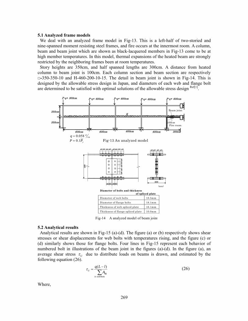
column to beam joint is 100cm. Each column section and beam section are respectively □-350-350-10 and H-460-200-10-15. The detail in beam joint is shown in Fig-14. This is designed by the allowable stress design in Japan, and diameters of each web and flange bolt are determined to be satisfied with optimal solutions of the allowable stress design Ref[1].
5.2 Analytical results Analytical results are shown in Fig-15 (a)-(d). The figure (a) or (b) respectively shows shear
stresses or shear displacements for web bolts with temperatures rising, and the figure (c) or (d) similarly shows those for flange bolts. Four lines in Fig-15 represent each behavior of numbered bolt in illustrations of the beam joint in the figures (a)-(d). In the figure (a), an average shear stress Uτ due to distribute loads on beams is drawn, and estimated by the following equation (26).
∑∈
−=
botswebiBi
U AlLq )(τ (26)
Where,
40 60 60 40 4060 60 40
4060
4060
60
460
4040 4040
5
Fig-14 A analyzed model of beam joint
200
40 40 40 40
(mm)
Diameter of bolts and thickness of spliced plate
Diameter of web bolts 18.5mm
Diameter of flange bolts 18.1mm Thickness of web spliced plate 16.1mm
Thickness of flange spliced plate 10.0mm
350cm
Beam joint
Fire room
Fig-13 An analyzed model
300cm
q
600cm600cm600cm
100cm
600cm
350cm
P-q× 300cm P-q× 600cm P-q× 600cm P-q× 600cm P-q× 600cm
yPP 1.0=cm
tfq 058.0=

270
q : distribute loads on the heated beam L : a half beam spanned length l : a distance between the heated column and the beam joint
BA : a shear section of web bolt For the member temperatures bellow 400℃, thermal stresses grown into the heated beam are
increasing with a vengeance. This is because that thermal expansions of the heated beam are strongly restricted by the neighboring frames. The thermal stresses stop to increase as soon as member temperatures lead to above 400℃ , and after that, begin to decrease. These phenomena are caused by stress redistributions with plastic deformations growing into the heated beam. A difference among each shear stress in the figure (a) corresponds to a difference in loaded
bending moments for web bolts. A shear stress of No.1 bolt is bigger than the others in order to superpose two axial forces due to the thermal stress and the bending moment. As in the figure (a), we understand that each share stress is decreasing with the thermal stresses decreasing and loaded bending moments for web bolts similarly are decreasing at temperatures above 500℃. This decrease in bending moments is redistributed into the flange bolts with plastic deformations of web bolts growing. After that, shear stresses of all web bolts gradually come to be uniformly with temperatures rising. When the member temperature leads to 702℃, shear stresses of all web bolts approximately
0 200 400 600 8000
0.1
0.2
0.3
0.4
0.5
温度(℃)
ボル
トの変
形量
(c
m)
1
2
34
(b) Shear displacements of web bolts
Δ (
cm)
T (℃)
1234
柱側
梁中央側
Fig-15 Analytical results
0 200 400 600 8000
1
2
3
4
5
温度(℃)
ボル
トのせ
ん断
応力
度
(tf/c
㎡)
1234
作用平均せん断応力
(a) Shear stresses of web bolts
τ (tf
/cm
2 )
T (℃)
τ U
1 2 3 4
柱側
梁中央側
0 200 400 600 8000
1
2
3
4
5
温度(℃)
ボル
トの
せん
断応
力度
(tf/
c㎡)
1:実線2:破線3:一点鎖線
(c) Shear stresses of flange bolts
T (℃)
τ (tf
/cm
2 )
1 2 3
柱側
梁中央側
1: Solid line 2: Dash line 3: Alternate long
and short dash line
0 200 400 600 8000
0.1
0.2
0.3
0.4
0.5
温度(℃)
ボル
トの
変形
量
(cm
) 1:実線2:破線3:一点鎖線
T (℃)
Δ (
cm)
(d) Shear displacements of flange bolts
1 2 3
柱側
梁中央側
1: Solid line2: Dash line 3: Alternate long
and short dash line
Special and rigid elements
Fig-17 Displacements of beam joint(web) at ultimate temperatures(702℃)
Bolt elements
梁継手
火災層Fire room
Beam joint
Fig-16 Displacements of steel frames at ultimate temperatures(702℃)

271
come to be equal to Uτ , and the beam joints can transfer shear forces no longer. This namely indicates that no thermal stresses and no bending moments are shared in web bolts. This state is exactly an ultimate state for this frame, and an ultimate temperature is 702℃. A collapse mode of this frame is a shear failure of beam joint. Actually, as in the figure (b), shear displacements of all web bolts are sharply increasing. On the other side, those of all flange bolts are about 0.05cm, and have been sound until it leads to the ultimate states. The shear displacements of all bolts in the beam joints have been under 0.5cm for member
temperatures bellow 702℃. It is, consequently, considered that the plastic shear deformed capacity for a bolt is sufficient to induce stress redistributions for the overall frames and the beam joint in this analytical result. 6. Conclusions This paper has presented finite element models for beam joints in steel frames subject to fire,
and these have the following features. 1. This finite element models for beam joints consist of 3D H-sectional models assembled
by flange plates, web plates and splice plates which are 2D rectangular elements. An Acting shear force between the beam and the spliced plate are transferred through a bolt element which has an elasto-plastic shear spring.
2. In this paper, relationships between shear stresses and shear displacements for a heated high strength bolt are estimated from the equations (18) and (19). These equations are based on the past experiments on shear strengths of high strength bolts for various temperatures.
3. To analyze behaviors of overall steel frames with beam joints, the 3D bolt joint model is incorporated into adjacent 2D beam elements with rigid beam elements and truss elements in this finite element models.
References [1] AIJ (2001). “Recommendation for design of connections in steel structures” (in Japanese) [2] AIJ (1999). “Recommendation for fire resistant design of steel structures” (in Japanese) [3] B.R.Kirby (1995). “Behaviour of High-strength Grade 8.8 Bolts in Fire” J. Constructional Steel
Research, Vol33 [4] Nakagawa H. et al. (1999). “Ultimate Temperatures of Steel Beams Subject to Fire” J. Steel
Construction Engineering Vol.6 No.22 (in Japanese) [5] Furumura F., Abe T., Okabe T., Kim W. J. (1986). “A uniaxial stress-strain formula of structural steel at
high temperature and its application to thermal deformation analysis of steel frames,” J. Structural and Construction Eng,, AIJ, 363 (in Japanese).
[6] Nakagawa H(1999). “Ultimate Temperatures of Steel Beams Subjected to Fire” A thesis of doctorate, Uni. of Tsukuba (in Japanese)
[7] O.C.Zienkiewicz (1971). “The Finite Element Method in Engineering Science” McGraw-Hill, London [8] Y.Sakumoto, K.Keira, F.Furumura, and T.Ave (1993) “TESTS OF FIRE-RESISTANT BOLTS AND
JOINTS”, Journal of Structural Engineering, ASCE vol.119, No.19. [9] Hirashima T. (2000). “Experiments about shear strength of friction type high tension bolted joints at
elevated temperature” J. Structural Eng. Vol.47 B (in Japanese) [10] J. W. Fisher (1965). ”BEHAVIOR OF FASTENERS AND PLATES WITH HOLES” Jour. Of the ST.
div., Proc. Of the ASCE

272
[11] Suzuki H. (1995). “Ultimate temperatures of steel frames subjected to fire,” J. Structural and Construction Eng., AIJ, 477 (in Japanese).