Finite Element Modelling of Asphalt Concrete Pavement...
9
International Journal of Materials Chemistry and Physics Vol. 2, No. 2, 2016, pp. 62-70 http://www.aiscience.org/journal/ijmcp Finite Element Modelling of Asphalt Concrete Pavement Reinforced with Geogrid by Using 3-D Plaxis Software Mohammed Abbas Hasan Al-Jumaili * Department of Civil Engineering, Faculty of Engineering, University of Kufa, Najaf City, Iraq Abstract This paper studied the application of 3-D Plaxis software on reinforced asphalt concrete pavement with geogrid layer at two positions within the pavement structure to investigate effect of geogrid on the critical pavement responses such as total stress and vertical surface displacement. An axisymmetric finite element model was loaded with an incremental cycling contact pressure from 50 to 600 kPa and the geogrid layer was placed either at the bottom of surface asphalt concrete or at top of subbase course to study influence of geogrid position on pavement performance. The analysis results indicated that under various tire pressure values, a significant effect on the pavement behaviour was observed when the geogrid layer was located at bottom of asphalt concrete surface layer. The Plaxis output results also showed a moderate improvement in pavement system response was obtained when geogrid reinforcement layer was placed at top of subbase layer. Keywords Asphalt Concrete, Georid, 3-D Plaxis and Vertical Displacement Received: January 9, 2016 / Accepted: January 27, 2016 / Published online: February 16, 2016 @ 2016 The Authors. Published by American Institute of Science. This Open Access article is under the CC BY-NC license. http://creativecommons.org/licenses/by-nc/4.0/ 1. Introduction The high modulus polymer geogrid has been utilized within the asphalt concrete courses during the past few decades to enhance flexible pavement behaviour and its performance . The geogrid will resist the fatigue stress and strain at bottom of asphalt concrete course due to it has the tensioned membrane effect. The Geogrid-reinforcement layer can be placed at the sub base - sub grade interface or between the base course and sub-base to to reduce total rutting failure at pavement surface [1]. The use of geogrid reinforcement in construction of highway pavement started in the 1970s. Then, the technique of geogrid reinforcement has been increasingly used and many experimental and analytical studies have been performed to assess geogrid behaviour in the flexible pavement [2, 3, 4, and 5]. Pandey et al. [6] studied a two dimensional axisymmetric FE model was used to analyse the response of geogrid reinforced bituminous pavement subjected to static and dynamic loading. They found that the fatigue (horizontal) stain reduced when geogrid was placed at base -bituminous concrete interface. The results showed that placing geogrid layer at the interface of base and subgrade layers caused the highest reduction in vertical strain. Barksdale et. al. [7] investigated the structural performance of unreinforced and geogrid reinforced pavement subjected to laboratory cycling loading testing. The vertical permanent deformation was measured of both unreinforced and geogrid reinforced pavement. The results indicated the stiff geogrid placed at the bottom of granular base did not give any significant improvement for a strong pavement whereas the placing the geogrid at bottom of the base layers resulted in better performance (low permanent deformation) than the use of a geotextile. They carried out FE simulation analysis techniques and showed that the benefits of geosynthetic reinforcements are more pronounced for weaker subgrades. Moayedi et. al. [8] used the FE PLAXIS program to study the effect of geogrid reinforcement in flexible pavement by developed the axisymmetric pavement response model under
Transcript of Finite Element Modelling of Asphalt Concrete Pavement...

International Journal of Materials Chemistry and Physics
Vol. 2, No. 2, 2016, pp. 62-70
http://www.aiscience.org/journal/ijmcp
Finite Element Modelling of Asphalt Concrete Pavement Reinforced with Geogrid by Using 3-D Plaxis Software
Mohammed Abbas Hasan Al-Jumaili*
Department of Civil Engineering, Faculty of Engineering, University of Kufa, Najaf City, Iraq
Abstract
This paper studied the application of 3-D Plaxis software on reinforced asphalt concrete pavement with geogrid layer at two
positions within the pavement structure to investigate effect of geogrid on the critical pavement responses such as total stress
and vertical surface displacement. An axisymmetric finite element model was loaded with an incremental cycling contact
pressure from 50 to 600 kPa and the geogrid layer was placed either at the bottom of surface asphalt concrete or at top of
subbase course to study influence of geogrid position on pavement performance. The analysis results indicated that under
various tire pressure values, a significant effect on the pavement behaviour was observed when the geogrid layer was located at
bottom of asphalt concrete surface layer. The Plaxis output results also showed a moderate improvement in pavement system
response was obtained when geogrid reinforcement layer was placed at top of subbase layer.
Keywords
Asphalt Concrete, Georid, 3-D Plaxis and Vertical Displacement
Received: January 9, 2016 / Accepted: January 27, 2016 / Published online: February 16, 2016
@ 2016 The Authors. Published by American Institute of Science. This Open Access article is under the CC BY-NC license.
http://creativecommons.org/licenses/by-nc/4.0/
1. Introduction
The high modulus polymer geogrid has been utilized within
the asphalt concrete courses during the past few decades to
enhance flexible pavement behaviour and its performance .
The geogrid will resist the fatigue stress and strain at bottom
of asphalt concrete course due to it has the tensioned
membrane effect. The Geogrid-reinforcement layer can be
placed at the sub base - sub grade interface or between the
base course and sub-base to to reduce total rutting failure at
pavement surface [1]. The use of geogrid reinforcement in
construction of highway pavement started in the 1970s. Then,
the technique of geogrid reinforcement has been increasingly
used and many experimental and analytical studies have been
performed to assess geogrid behaviour in the flexible
pavement [2, 3, 4, and 5].
Pandey et al. [6] studied a two dimensional axisymmetric
FE model was used to analyse the response of geogrid
reinforced bituminous pavement subjected to static and
dynamic loading. They found that the fatigue (horizontal)
stain reduced when geogrid was placed at base -bituminous
concrete interface. The results showed that placing geogrid
layer at the interface of base and subgrade layers caused the
highest reduction in vertical strain. Barksdale et. al. [7]
investigated the structural performance of unreinforced and
geogrid reinforced pavement subjected to laboratory
cycling loading testing. The vertical permanent deformation
was measured of both unreinforced and geogrid reinforced
pavement. The results indicated the stiff geogrid placed at
the bottom of granular base did not give any significant
improvement for a strong pavement whereas the placing the
geogrid at bottom of the base layers resulted in better
performance (low permanent deformation) than the use of a
geotextile. They carried out FE simulation analysis
techniques and showed that the benefits of geosynthetic
reinforcements are more pronounced for weaker subgrades.
Moayedi et. al. [8] used the FE PLAXIS program to study the
effect of geogrid reinforcement in flexible pavement by
developed the axisymmetric pavement response model under
International Journal of Materials Chemistry and Physics Vol. 2, No. 2, 2016, pp. 62-70 63
static loading condition. Bituminous concrete layer and
geogrid were modeled as a linear elastic isotropic material
while the Moho-Coulomb material model was adapted to
represented granular base materials. They obtained that the
geogrid reinforcement placed at the bottom of bituminous
concrete layer reduced vertical pavement deflection.
Hamdy and Ahmed [9] studied a series of FE simulations by
Plaxis software on suggested pavement structures consisted
of asphalt concrete layer, base layer, subbase layer on
subgrade layer.They concluded a significant improvement in
pavement behavior by placing one –layer of geogrid
reinforcement where the vertical displacement and effective
stresses are lower in case of one geogrid layer or two
geogride layers.
In the present study, an attempt has been made to investigate
the influence of geogrid reinforcement at two positions
within the asphalt concrete system through the application of
3-D Plaxis software program. The geogride reinforcement
layer was firstly placed at bottom of surface asphalt concrete
layer and secondly the geogrid was placed at top of granular
subbase layer to investigate.
2. Finite Element Model
The flexible pavement system used in 3-D PLAXIS software
version 2013 consisted of asphalt concrete (AC) surface
layer, asphalt concrete (AC) base layer, granular subbase
layer and sandy subgrade layer subjected to repeated cycling
loading with 0.10 second loading period. The unreinforced
and geogrid reinforced pavement response was evaluated
under a repeated cycling loading (50, 100, 150, 200, 250,
300,350,400,450,500,550 and 600 )kPa acting on a circular
area of 0.15 m radius with frequency of 10 HZ which is
corresponding to 0.1 seconds duration . A triangular wave
with duration of 0.1 second corresponding to an average
speed of around 70 km/h was adopted in this study [10]. The
duration time between two subsequent axles is assumed to be
0.2 second.
The two asphalt concrete layers and geogrid were modeled as
a linear elastic isotropic material while the Mohr-Coulomb
model was used to model granular subbase and subgrade
materials.
An axisymmetric model was utilized in the analysis using
45900-noded structural solid elements with medium
refinement. Axisymmetric modeling was chosen in this study
because it could simulate circular loading and did not require
excessive computational time [2, 11].
Alex [12] indicted that the nodal radial strains were assumed
to be negligible at approximately10 times R (radius of loaded
area) from the area applied wheel load. Also, the nodal
stresses and displacements were assumed to be negligible at
20times R below the pavement surface. Therefore, the width
and the length of the model were set at 5m, and the total
thickness of model is 4m. Total pavement structure thickness
is 0.45 m above sandy subgrade depth of 3.55 m. The
thickness of AC surface course is 0.05 m, the thickness of AC
base course is 0.10 m while the thickness of granular subbase
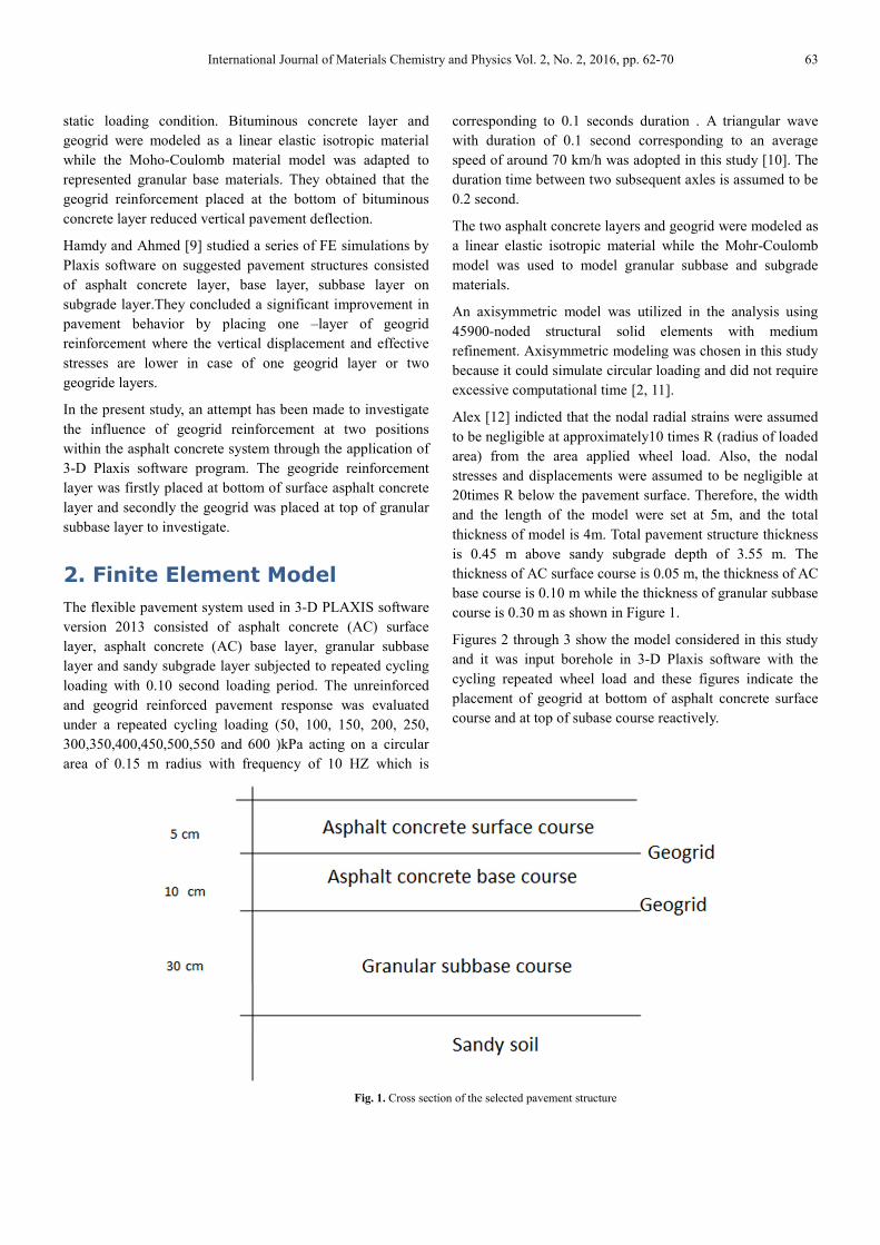
course is 0.30 m as shown in Figure 1.
Figures 2 through 3 show the model considered in this study
and it was input borehole in 3-D Plaxis software with the
cycling repeated wheel load and these figures indicate the
placement of geogrid at bottom of asphalt concrete surface
course and at top of subase course reactively.
Fig. 1. Cross section of the selected pavement structure

64 Mohammed Abbas Hasan Al-Jumaili: Finite Element Modelling of Asphalt Concrete Pavement Reinforced
with Geogrid by Using 3-D Plaxis Software
Fig. 2. FE axisymmetric model considered for reinforced pavement at bottom of asphalt concrete surface layer.
Fig. 3. FE axisymmetric model considered for reinforced pavement at top of subbase layer.
Since the resilient modulus test equipment is not currently
available in many laboratories, researchers have developed
correlations to converting CBR values to approximate MR
values. The correlation considered reasonable for fine
grained soils with a soaked CBR of 10 or less is [13]:
MR (MPa) = 10.3 * (CBR) (1)
The minimum limit of CBR value of subgrade will be taken
as 4% in accordance with Iraq specifications requirements
(SCRB /R5) [14]. Therefore, resilient modulus of subgrade
can be calculated from eq.(1) and it is founded as 40 MPa.
Claessen et al. [15] established the relation between subbase
resilient modulus and subgrade resilient modulus according
to the following relationship:
MR= 0.2 * h0.45
* MR (subgrade) (2)
Where
h = the thickness of subbase layer in mm.
In this study, the thickness of subbase layer is 300 mm and MR
for the subgrade was 40 MPa and as a result the MR value of
subbase course is 100 MPa. Material parameters and
constitutive models used are shown in Table (1) whereas Table
(2) shows mechanical properties of geogrid reinforcement.
Table 1. Pavement materials properties.
AC Surface AC Base Grave and sand Subbase Sand Subgrade
Model Linear elastic Linear elastic Mohr-Coulomb Mohr-Coulomb
Thickness(m) 0.05 0.1 0.3 2.55
Young’s modulus(MPa) 4000 3000 100 40
Poisson’s Ratio 0.35 0.35 0.45 0.45
Dry density(kN/m3) 23 23 20 17
Saturated density (kN/m3) --- --- 22 20
Cohesion(kN/m2) --- --- 20 8
Friction angle (degree) --- --- 40 35
Dilatation angle (degree) --- --- 15 5

International Journal of Materials Chemistry and Physics Vol. 2, No. 2, 2016, pp. 62-70 65
Table 2. Physical and mechanical properties of Netlon CE121 product.
Physical properties
Property Result
Mesh type Diamond
Standard color Black
Polymer type HDPE
Packaging Rolls
Dimensional properties
Property Unit Result
Aperture size mm 6*8
Mass per unit area g/m2 740
Rib thickness mm 1.6/1.45
Junction thickness mm 2.75
Rib width mm 2/2.75
Mechanical properties
Peak tensile resistance kN/m 6.4
Elastic modules GPa 0.39
Tensile strength MPa 9
Percentage elongation at maximum load % 6
3. Results and Analysis
In this section repeated cycling loading condition is presented
for both unreinforced and geogrid-reinforced base. Applied
contact pressure ranged from 50 kPa to 600 kPa and geogrid
was placed at two positions either at bottom of asphalt
concrete surface layer or at the interface of asphalt concrete
base layer and subbase course. Critical pavement responses
i.e. total stress and total vertical displacement of unreinforced
and geogrid reinforced pavements are determined under for
each contact pressure value.
Figures 4 through 6 illustrate the vertical displacement
profile for applied contact load of 600 kPa for case of
unreinforced pavement and reinforced pavement with one
layer of geogrid placed either under AC layer or above
subbase layer.
Fig. 4. Vertical displacement contour for unreinforced pavement (applied tire pressure =600 kPa).

66 Mohammed Abbas Hasan Al-Jumaili: Finite Element Modelling of Asphalt Concrete Pavement Reinforced
with Geogrid by Using 3-D Plaxis Software
Fig. 5. Vertical displacement profile for reinforced pavement with geogrid at bottom of AC surface layer (applied tire pressure =600 kPa).
Fig. 6. Vertical displacement contour for reinforced pavement with geogrid at top of subbase layer (applied tire pressure =600 kPa).
It may be observed from above figures that a significant
decrease in vertical settlement obtained for reinforced
pavement at both of bottom of AC surface layer or top of
subbase layer. Maximum vertical displacement is 4.213x10⁻³
m for case of unreinforced pavement, while it is -3.518x10⁻³
m and -3.675*10-3
m for reinforced AC surface and at top of
subbase pavement courses respectively. It can be concluded
that the reduction in vertical displacement (rutting) at
pavement surface by 16.5% when geogrid was placed at
bottom of AC surface course.
Figures 7 to 9 illustrate the total stresses profiles for applied
tire pressure of 600 kPa for case of unreinforced pavement
and reinforced pavement with geogrid placed under AC
surface layer and at top of subbase layer respectively.

International Journal of Materials Chemistry and Physics Vol. 2, No. 2, 2016, pp. 62-70 67
Fig. 7. Total stresses contour for unreinforced pavement (applied tire pressure = 600 kPa).
Fig. 8. Total stresses contour for reinforced pavement with geogrid at bottom of AC surface layer (applied tire pressure = 600 kPa).

68 Mohammed Abbas Hasan Al-Jumaili: Finite Element Modelling of Asphalt Concrete Pavement Reinforced
with Geogrid by Using 3-D Plaxis Software
Fig. 9. Total stresses profile for reinforced pavement with geogrid at bottom of surface layer (applied tire pressure = 600 kPa).
Figures 6 through 8 indicated that for unreinforced pavement,
maximum total stress (335.9 kPa) is significantly higher
compared with that for case of reinforced pavement with
geogrid at bottom of surface layer (118.8 kPa) and reinforced
pavement with geogrid at top of subbase layer (224.5 kPa).
Figures 10 and 11 show comparison between pavement
system behaviour for three cases: unreinforced pavement,
geogrid reinforced pavement at bottom surface layer, and
geogrid reinforced pavement at top of subbase layer. The
three cases are compared in regards of total stress and
vertical settlement responses
Fig. 10. Maximum vertical displacement values of unreinforced and geogrid reinforced pavements.

International Journal of Materials Chemistry and Physics Vol. 2, No. 2, 2016, pp. 62-70 69
Fig. 11. Maximum total stress values of unreinforced and geogrid reinforced pavement.
Regardless of applied pressure values, the pavement with
geogrid reinforcement at bottom of AC surface layer has a
slightly lower maximum vertical displacement and total
stress than that of other cases as shown in Figures 10 and 11.
4. Conclusions
Based on 3-D Plaxis software outputs applied on pavement
structure to evaluate the benefits of reinforcing pavement
with geogrid at two positions, the following conclusions can
be drawn:
1 A significant improvement in pavement behavior is
obtained by placing geogrid layer at bottom of asphalt
concrete surface layer. Vertical displacement and effective
stress responses are significantly lower for reinforced
pavement system in comparison with unreinforced
pavement.
2 Moderate improvement in pavement system behavior was
gained by adding geogride at top of subbase layer.
3 The best location of adding geogrid within the pavement
structure is near to applied tire pressure within the asphalt
concrete layers.
4 The use of geogrid significantly enhances the resistance of
asphalt concrete to the deformation and development of
cracking failure.
References
[1] Pandey, S., Rao, K. R. and Tiwari, D. (2012). Effect of geogrid reinforcement on critical responses of bituminous pavements. 25th ARRB Conference –Shaping the future: Linking policy, research and outcomes, Perth, Australia.
[2] Howard, I. L. and Warren, K. A. (2009). Finite-element modeling of instrumented flexible pavements under stationary transient loading. J. Transportation Eng. ASCE, 135 (2): 53-61.
[3] Perkins, S. W. (2001). Mechanistic-empirical modeling and design model development of geosynthetic reinforced flexible pavements. Montana Department of transportation, Helena, Montana, Report No. FHWA/MT-01-002/99160-1A.
[4] Perkins, S. W. (2002). Evaluation of geosynthetic reinforced flexible pavement systems using two pavement test facilities. Report No. FHWA/MT-02-008/20040, U.S. Department of Transportation, Federal Highway Administration.
[5] Berg, R. R., Christopher, B. R., and Perkins, S. W. (2000). Geosynthetic reinforcement of the aggregate base course of flexible pavement structures. GMA White paper II, Geosynthetic material Association, Roseville, MN, USA, 130 p.
[6] Perkins, S. W., Ismeik, M. and Fogelsong, M. L. (1999). Influence of geosynthetic placement position on the performance of reinforced flexible pavement systems. Proceedings of the Conference Geosynthetics ‘99, Boston, MA, USA, Vol. 1, pp. 253-264.
[7] Barksdale, R. D., Brown, S. F., and Chan, F. (1989). Aggregate base reinforcement of surfaced pavement. Geotext. Geomembrane, 8, pp. 165–189.
[8] Moayedi, H., Kazemian, S., Prasad, B. and Huat (2009). Effect of Geogrid Location in Paved Road Improvement. Journal of EJGE, Vol.14, pp.3313-3329.
[9] Hamdy, F. and Ahmed M. H. (2014). 2D Plaxis finite element modeling of asphalt-concrete pavement reinforced with geogrid. Journal of Engineering Sciences Assiut University Faculty of Engineering, Vol. 42No. 6, November 2014, pp. 1336–1348.
[10] LCPC-SETRA. (1997). French Design Manual for Pavement Structures .Paris: Laboratoire Central des Ponts et Chaussées and Service d’Etudes Techniques des Routes et Autoroutes.

70 Mohammed Abbas Hasan Al-Jumaili: Finite Element Modelling of Asphalt Concrete Pavement Reinforced
with Geogrid by Using 3-D Plaxis Software
[11] Kazemian, S., Barghchi, M., Prasad, A., Maydi, H. and Huat, B.K. (2010). "Reinforced pavement above trench under urban traffic load: Case study and finite element (FE) analysis", Journal of Scientific Research and Essay Vol. 5 (21), Nov.4, 2010, pp. 3313-3328.
[12] Alex, A., (2000). Characterization of Unbound Granular Layers in Flexible Pavements. Report No. ICAR/502-3, Texas Transportation Institute.
[13] AASHTO, (1993). AASHTO guide for design of pavement structure–1993. The American Association of State Highway and Transportation Officials, Washington, D.C.
[14] SCRB/R9, (2003). General Specification for Roads and Bridges, Section R/9, Hot-Mix Asphalt Concrete Pavement. Revised Edition. State Commission of Roads and Bridges, Ministry of Housing and Construction, Republic of Iraq.
[15] Claessen, A., P. Edwards, P. Sommer, and P. Uge, (1977). Asphalt pavement design: the SHELL method. Proceedings Fourth International Conference on the Structural Design of Asphalt Pavements, the University of Michigan, Ann Arbor, Michigan, USA.


![ASPHALT CONCRETE [Types] - KSU Facultyfac.ksu.edu.sa/sites/default/files/AC-1-LabTYPESDISTRESS.pdf · ASPHALT CONCRETE [Types] Introduction ... Sand Asphalt Mix Sand asphalt mixes](https://static.fdocuments.net/doc/165x107/5b72d5437f8b9a674d8d5d0c/asphalt-concrete-types-ksu-asphalt-concrete-types-introduction-sand.jpg)


![Finite Element Analysis of Performance of Asphalt Pavement ......FE. Turner et al. presented a concept method of finite elements [2]; Zienkiewicz, Taylor and Reddy devoted the theory](https://static.fdocuments.net/doc/165x107/60e9c7779cb51a3e0732baad/finite-element-analysis-of-performance-of-asphalt-pavement-fe-turner-et.jpg)