Finite Element Elastic-Plastic- Creep and Cyclic Life … · · 2013-08-30/it) NASA Technical...
11
/it) NASA Technical Memorandum 102342 Finite Element Elastic-Plastic- Creep and Cyclic Life Analysis of a Cowl Lip Vinod K. Arya University of Toledo Toledo, Ohio and Matthew E. Melis and Gary R. Halford Lewis Research Center Cleveland, Ohio I ORIGINAL UiAINS COLOR ILLUSTRATIONS April 1990 A-J-1J?.J+-) t IIT r LThT ASTIC-PLASTIC-C'EP ANU CYCLIC LIFE A1YIS OF A COWL LIP (NASA) 10 pCSCL 20K fi Unci as '- .:/3' 0'7S3' https://ntrs.nasa.gov/search.jsp?R=19900013492 2018-06-02T22:30:27+00:00Z
Transcript of Finite Element Elastic-Plastic- Creep and Cyclic Life … · · 2013-08-30/it) NASA Technical...

/it)
NASA Technical Memorandum 102342
Finite Element Elastic-Plastic-Creep and Cyclic Life Analysis of a Cowl Lip
Vinod K. Arya University of Toledo Toledo, Ohio
and
Matthew E. Melis and Gary R. Halford Lewis Research Center Cleveland, Ohio
I
ORIGINAL UiAINS
COLOR ILLUSTRATIONS
April 1990
A-J-1J?.J+-) t IIT r LThT ASTIC-PLASTIC-C'EP ANU CYCLIC LIFE A1YIS OF A COWL LIP (NASA) 10 pCSCL 20K
fi
Unci as '- .:/3' 0'7S3'
https://ntrs.nasa.gov/search.jsp?R=19900013492 2018-06-02T22:30:27+00:00Z

FINITE ELEMENT ELASTIC-PLASTIC-CREEP AND CYCLIC LIFE ANALYSIS OF A COWL LIP
Vinod K. Arya University of Toledo Toledo, Ohio 43606
and
Matthew E. Melis and Gary R. Halford National Aeronautics and Space Administration
Lewis Research Center Cleveland, Ohio 44135
Summary
Results are presented of elastic, elastic-plastic, and elastic-plastic-creep analyses of a test-rig component of an actively cooled cowl lip. A cowl lip is part of the leading edge of an engine inlet of proposed hypersonic aircraft and is subject to severe thermal loadings and gradients during flight. Values of stresses calculated by elastic analysis are well above the yield strength of the cowl lip material. Such values are highly unrealistic, and thus elastic stress analyses are inappropriate. The inelastic (elastic-plastic and elastic-plastic-creep) analyses produce more reasonable and acceptable stress and Strain distributions in the component. Finally, using the results from these analyses, predictions are made for the cyclic crack initiation life of a cowl lip. A comparison of predicted cyclic lives shows the cyclic life prediction from the elastic-plastic-creep analysis to be the lowest and, hence, most realistic.
Introduction
A significant research effort was launched recently at NASA Lewis Research Center to develop state-of-the-art technologies for hypersonic flight between Mach 3 and 25. At such high speeds, the leading edges of hypersonic aircraft are subjected to high heat fluxes and, thus, high temperatures and severe thermal gradients. To achieve high inlet aerodynamic performance, not only must the high heating rates be tolerated, but also distortions caused by thermal warping of the structure must be minimized. Consequently, the need arises for the
development of actively cooled leading edges fabricated from specialized materials with innovative cooling concepts to enable the structure to withstand the severe environmental conditions. The details of different cooling concepts proposed and studied under a NASA Lewis sponsored program, called COLT (Cowl Lip Technology Program), were presented by Melis and Gladden.'
Under the severe thermal loadings and gradients experienced by the component, a propensity for significant inelastic deformation of the material exists. The intent of the present work was to perform linear (elastic) and nonlinear (elastic-plastic and elastic-plastic-creep) structural analyses of the cowl lip for a crossflow cooling concept,' and to assess potential durability to low-cycle fatigue cracking. In crossflow cooling, the direction of coolant flow is perpendicular to that of the hot gas. (See Figure 1.) A comparison of service lives predicted from the outputs of the three structural analyses is also presented. The three-dimensional finite element model and steady-state heat transfer results were obtained from Reference 1. The imposed thermal loadings obtained from a rig test of a cowl lip are shown in Figure 2. Measured gas and wall temperatures are shown for one complete cycle. For ease of calculations, the leading-edge metal temperature was approximated by a simplified temperature cycle. This sim-ulated thermal loading cycle, shown in Figure 2(c), was used in subsequent calculations. Nonlinear variations in the material constants with temperature were accounted for in the computations. The life assessment calculations for the cowl lip were performed by using data from the existing literature. 2 Details of the finite element model and thermal,
OR%G%AL CONTAINS
COLOR ILLUSTRATIONS

structural, and life analyses of the cowl lip are presented in the following sections.
Analyses
Finite Element Model
A three-dimensional, finite element model of the cowl lip (Figure 1) was constructed by Melis and Gladden.' The model consists of 3294 eight-noded, solid, isoparametric elements and 4760 nodes. The dimensions of the rig component are 6 by 1.5 by 0.25 in. (15.2 by 3.8 by 0.6 cm). The cowl lip finite element model consists of the central 2-in. (5-cm) portion of the component. This small section was analyzed to avoid the difficult-to-quantify constraining effects of the ends. A considerably large number of elements are required to handle the severe thermal loadings imposed on the com-ponent. The severity of thermal loading, together with the fine-grid finite element model, makes the nonlinear structural analyses computationally intensive. However, taking advantage of the symmetry along the thickness reduces the computation time appreciably.
Heat Transfer Analysis
Reference 1 describes a boundary layer analysis conducted to compute the film coefficients. The authors used the boundary-layer heat transfer code STAN5 3 to estimate the film coefficients on the hot-gas side of the cowl lip. Correlative techniques 4,5 were employed to determine coefficients on the coolant side. The stagnation points and leading-edge-region film coefficients were ascertained from a "cylinder in crossflow" correlation. Using the film coefficients determined by these procedures, the authors performed a steady-state heat transfer analysis for the cowl lip. An instrumented rig component was tested in the Hot Gas Test Facility at NASA Lewis Research Center. 6 Thermal loadings are displayed in Figures 2(a) and (b).
Structural Analyses
Linear elastic and nonlinear elastic-plastic analyses were performed by using the finite element program MARC. 7 The material of the cowl lip was copper. The temperature dependence of Young's modulus E and the coefficient of instantaneous thermal expansion a, taken from Freed and Verrilli, 8 are listed in table I. The elastic Poisson's ratio v was assumed to be 0.34 for all temperatures.
The structural response of the cowl lip was calculated by using an eight-noded solid brick element. This element was compatible with the element used for the heat transfer analysis. The steady-state temperature values (between 0.75 and 2.25 sec in fig. 2(c)) were obtained from Reference 1. A linear interpolation technique was then employed to obtain the transient temperature values (in the periods between 0 and
TABLE 1.—MATERIAL CONSTANTS FOR COPPER
Young's modulus, E, ksi ......... . 18 504.0 - 3.164 Tb - 0.0022 7'2 Coefficient of thermal expansion, a ...... 1.59x10- 5 + 2.78x10- 9 T Poisson's ratio, v ........................................................... 0.34 A, sec' ............................................................... 3.Ox 1024 n ................................................................................. 5.0 m ............................................................................... 0.35 Activation energy, i/mole
Lattice diffusion, QL ............................................... 2.Ox 105 Pipe diffusion, Q, .................................................. 1.2x10
X........................................................................ 1.8x10⁻⁵ Boltzmann's constant, i/mole K ....................................... 8.314
aI ksi 6.895 MPa. bT is temperature in degrees Celsius.
0.75 sec and 2.25 and 3 sec) to describe the temperature distribution over the complete thermal loading cycle. For the nonlinear elastic-plastic analysis, a combined isotropic and kinematic hardening plasticity law was employed. The tem-perature and hardening effects were incorporated in the analysis through the input for the finite element program MARC.
To investigate the time-dependent response of the cowl lip, a nonlinear combined elastic-plastic-creep stress analysis was performed. The following creep law was used in the analysis:
(;0 €=AO tm—I (1)
where
o = exp + X exp / _Q kTk)
(2)
In these equations, u, is the effective stress; E is Young's modulus; t is the time; A, n and m are material constants; QL and Qp are the activation energies for lattice and pipe diffusion, respectively; X is the constant to account for the activation energy for pipe diffusion that must be included in the temperature function 0 above a homologous temperature of about 0.5 (see Figure 3); k is Boltzmann's constant; and Tk is the temperature in degrees Kelvin. This form of the creep law was obtained by using the experimental data of Barrett and Sherby 9 and Freed and Verrilli 8 and is shown in figures 3 and 4, respectively. The material constants appearing in the creep law for copper are listed in table I.
Elastic analysis.—Figures 5 and 6 depict, respectively, the elastically calculated stress and total strain distributions along a cross section of the cowl lip at thermal steady state. The total strain in this work does not include the thermal component of strain. Only a cross section of the component is shown in these figures. Since the largest compressive stresses and total (mechanical) strains occur along the leading edge (z-direction),

TABLE 11.-COMPARISON OF HYSTERESIS LOOP CHARACTERISTICS
Analysis Effective stress Effective stess Total Elastic Plastic Creep Cycles at maximum range mechan- strain strain strain to temperature ical range, range, range, failure,
ksi MPa Strain range
AEC, pp AEPC N
ksi MPa
Elastic -80.4 -554.4 105.4 726.7 0.0062 0.0062 2300
Elastic- -1.4 9.7 8.82 60.7 .0085 .0005 0.0080
-
-1000 plastic
Elastic- -1.3 -9.0 8.7 60.0 .0092 .0005 (= ).0080 (an).0007 800 plastic-creep
aStress range between points A and B of hysteresis loop of figure 12.
graphs showing these distributions are included in the dis-cussion. The magnitude of the largest stress predicted from the elastic analysis (see Figure 5) is much higher than the yield strength values for the copper material. This clearly indicates the inappropriateness of an elastic stress analysis for this severe thermally driven problem. The subsequently large imposed mechanical strains at these high temperatures are well above the yield strain and hence are expected to result in significant inelastic flow, necessitating a nonlinear inelastic stress-strain analysis.
Elastic-plastic analysis. -The stress and strain results of an elastic-plastic analysis of the cowl lip problem are shown in Figures 7 and 8. These figures exhibit the stress and strain distributions along the leading edge (z-direction). The analysis shows the reduction of maximum compressive stress to a more reasonable value of 28.5 ksi (196.5 MPa) from about 80.4 ksi (554.4 MPa) obtained from the elastic analysis. From Figure 8, the largest compressive strain occurring at the leading edge is greater than that obtained from the elastic analysis. This indicates the existence of compressive plastic strains along the edge.
Elastic-plastic-creep analysis.-To study the effects of time on stress and strain distributions in the cowl lip, a time-dependent creep analysis was also performed. The results are displayed in Figures 9 and 10. These figures show that the maximum compressive stresses and total strains still occur at the leading edge. The magnitude of maximum stress decreases, whereas the magnitude of total strain increases. This increase in strain magnitude implies the existence of compressive creep strains along the leading edge. During the steady state of thermal loading (i.e., between 0.75 and 2.25 sec), no further redistribution of stress due to creep is observed. This is made clear by comparing figures 9 and 11, which show the stress distributions in the cowl lip at 0.75 and 2.25 see, respectively.
Life Analysis
The stress-strain results from the structural analyses were used in estimating the cyclic crack initiation life of the cowl lip. The thermomechanical fatigue (TMF) hysteresis loops of
effective* stress and strain from the elastic-plastic-creep analyses are calculated for the "critical" cowl lip location (i.e., where the total strain range is maximum). In establishing these loops, the algebraic signs of effective stress and strain are dictated by the signs of the maximum principal stress and strain. This is in accordance with the recommendations of Manson and Halford' 0 for dealing with multiaxial stress-strain states. Critical-location stress-strain hysteresis loops for the first two complete loading cycles are presented in Figure 12. Table II shows a comparison of hysteresis loop characteristics (stress range, total strain range, elastic strain range, inelastic strain range, plastic strain range, and the approximate creep strain range) for the three different (elastic, elastic-plastic, and elastic-plastic-creep) structural analyses conducted. The elastic analysis calculates the smallest total strain range, whereas the elastic-plastic-creep analysis produces the largest. Because the latter strain range is about 50 percent larger than the smallest, the cowl-lip structural geometry apparently offers only limited constraint to the inelastically deformed material at the leading edge. Hence, the concept of total strain invariance suggested by " for highly constrained, thermally dominated loading problems should not be used for the limited geometric and thermal constraint found in the current problem.
The difference in inelastic strain range between the elastic-plastic and the elastic-plastic-creep results can be attributed to creep deformation; the creep strain range listed in the table is defined simply as this difference. The large inelastic strain range is dominated in this instance by time-independent plasticity. Furthermore, because of the very large strain range, the loops of figure 12 exhibit a high degree of symmetry about the zero stress axis. This gives rise to remarkably well-balanced hysteresis loops that exhibit little of the unbalanced
Effective stress = - [ (Ui - 02)2 + (02 - 03)2 + (03 -
112 effective strain u = - - 2)2 + (2 - 3)2 + (u3 - t1)]

characteristics (CP- and PCtypet hysteresis loops) normally associated with thermomechanical cycling at much smaller strain ranges. 12 Consequently, the hysteresis loops are composed of inelastic strain ranges of the balanced PP- and CC-types. The CC portion of the inelastic strain range is imposed quite naturally near the very highest temperature, whereas the PP strain range is imposed over the entire spectrum of temperatures from lowest to highest.
Because of the large inelastic strains imposed at the critical location, a strain-based, high-temperature, life prediction approach was sought. Ideally, the most accurate approach would be to generate TMF data for the alloy in question. Unfortunately, TMF data are virtually impossible to generate in the laboratory under the high loading and heating rates encountered in the current problem. Thus, approximations have been necessary to establish a relation between strain range and cyclic crack initiation life that would be applicable for use in predicting life for the current problem.
Isothermal, strain-controlled, low-cycle fatigue results have been reported by Conway, Stentz, and Berling 2 for annealed oxygen-free, high-conductivity (OFHC) copper at 1000 °F (538 'C) for a nonoxidizing, argon atmosphere. These results are shown in Figure 13. At the strain range of current interest (approximately 0.009), the frequency of loading is about 0.1 Hz. This frequency is slightly lower and thus more degrading than that of the cowl-lip TMF cycle (0.33 Hz, nonoxidizing, gaseous hydrogen environment). Because of the relative temperature insensitivity of the tensile ductility of OFHC copper and dilute alloys of copper such as zirconium-copper (variations measured at NASA Lewis range from 81 to 89 percent reduction of area over the temperature range of concern), low-cycle fatigue resistance is also expected 14
to be insensitive to temperature over the range of current interest. Thus, the fatigue curve of Figure 13 serves as a reasonable approximation to the TMF resistance of the cowl lip problem at hand. Respective total strain ranges of 0.0062, 0.0085, and 0.0092 for the elastic, elastic-plastic, and elastic-plastic-creep analyses correspond to cyclic crack initiation lives of 2300, 1000, and 800. Since the elastic-plastic-creep analysis is judged to give the most realistic structural analysis results, the corresponding life of 800 cycles to failure is also judged to be the most realistic estimate of expected lifetime. Note that, for the present problem, use of an elastic analysis to obtain the total strain range (i.e., using the concept of total strain invariance 1 I) would have resulted in a life prediction of about a factor of 3 too high (i.e., unconservative). It should be noted that the predicted life of 800 cycles is based solely on a low-
Me CP, PC, CC, and PP terminology for describing the hysteresis loops derives from the strainrange partitioning life prediction method of Manson, Halford, and Hirschberg. 13 The letter P refers to time-independent plasticity and C to time-dependent, thermally activated, creep deformation; the first letter refers to the tensile and the second to the compressive inelastic strains.
cycle fatigue criterion for failure. Other failure modes such as thermal ratcheting could further degrade cyclic durability.
Conclusions
Elastic, elastic-plastic, and elastic-plastic-creep analyses for the cowl lip were performed. A purely elastic stress-strain analysis for the problem is found inappropriate, since it calculates values of maximum stresses along the leading edge that are much larger than the yield strength of the copper used to manufacture the cowl lip. The elastic-plastic or elastic-plastic-creep analyses are found to produce more reasonable and hence acceptable values of stresses. This clearly indicates the necessity for performing inelastic analyses for severely loaded structural components.
The estimations for cyclic crack initiation life of the cowl lip were made by using the results from the elastic, elastic-plastic, and elastic-plastic-creep analyses. The lowest expected life of 800 cycles is obtained by using the results from the most realistic elastic-plastic-creep analysis. Use of an elastic analysis gives an expected life of 2300 cycles, about a factor of 3 higher than that obtained from the elastic-plastic-creep analysis.
References
1. M.E. Melis and H.J. Gladden, "Thermostructural Analysis With Experimental Verification in a High Heat Flux Facility of a Simulated Cowl Lip," in29th Structures, Structural Dynamics and Materials Conference, Part 1, AIAA, New York, 1988, pp. 106-115.
2. J.B. Conway, R.H. Stentz, and J.T. Berling, "High Temperature, Low-Cycle Fatigue of Copper-Base Alloys in Argon; Part I—Preliminary Results for 12 Alloys at 1000 'F (538 'C)," NASA CR-121259, 1973.
3. M.E. Crawford and W.M. Kays, "STAN5: A Program for Numerical Computation of Two-Dimensional Internal and External Boundary Layer Flows," NASA CR-2742, 1976.
4. R.C. Hendricks et al., "Bulk Expansion Factors and Density Fluctuations in Heat and Mass Transfer," in XV International Congress on Refrigeration, 1979, Paper B1-1 19.
5. W.M. Rohsenow and H.Y. Choi, Heat, Mass and Momentum Transfer, Prentice Hall, Englewood Cliffs, NJ, 1961.
6. M.E. Melis et al., "A Unique Interdisciplinary Research Effort to Support Cowl Lip Technology Development for Hypersonic Applications," NASA TP-2876, 1989.
7. MARC General Purpose Finite Element Program, MARC Analysis Research Corporation, Palo Alto, CA, 1983.
8. A.D. Freed and M.J. Verrilli, "A Viscoplastic Theory Applied to Copper," NASA TM-100831, 1988.
9. C.R. Barrett and O.D. Sherby, "Steady-State Creep Characteristics of Polycrystalline Copper in the Temperature Range of 480 'C to 950 'C," Trans. AIME, 230, 1322-1327 (1964).
10. S.S. Manson and G.R. Halford, "Treatment of Multiaxial Creep-Fatigue by Strainrange Partitioning," in 1976 ASME-MPC Symposium on Creep-Fatigue Interaction (R.M. Curran, Ed.), ASME, New York, 1976, pp. 299-322.
ii. S.S. Manson, Thermal Stress and Low-Cycle Fatigue, McGraw-Hill, 1966.

00 1 2 3 4 5
TIME. SEC
(b) MEASURED TRANSIENT LEADING-EDGE THERMOCOUPLE DATA.
800 1500
I 1250
600 - .1000
LU LU
I- I-
:100 750 LU Ui
LU Ui
500 U)
200 LD
250
12. G.R. Halford, "Low-Cycle Thermal Fatigue,' in Thermal Stresses II (R.B. Hetnarski, Ed.), Elsevier, 1987, pp. 329-428.
13. S.S. Manson, G.R. Halford, and M.H. Hirschberg. "Creep-Fatigue Analysis by Strain-Range Partitioning," in Design for Elevated Temperature Environment (S.Y. Zamrik, Ed.), ASME, New York, 1971, pp. 12-28.
14. G.R. Halford, M.H. Hirschberg, and S.S. Manson, "Temperature Effects on the Strainrange Partitioning Approach for Creep-Fatigue Analysis," in Fatigue at Elevated Temperatures, ASTM-STP-520, (A.E. Carden, A.J. McEvily, and C.H. Wells, Eds.), American Society for Testing and Materials, Philadelphia, PA, 1973, pp. 658-667.
COOLANT
FLOW
Figure 1.—Cowl lip finite element model.
1600
F
3000
2500
,, 1200 -o I 0
I .2000 Cr
I w = =
800 J- - 1500
1000
'lOOI— Lo
500
0 .5 1.0 1.5 2.0
TIME, SEC
(a) MEASURED HOT GAS TEMPERATURES FOR THREE TESTS
IN HOT GAS FACILITY.
0 .75 1.50 2.25 3.00 3.75 TIME. SEC
(C) SIMULATED THERMAL RESPONSE USED IN STRUCTURAL ANALYSES.
Figure 2.—Measured and approximated temperature distributions.
5

1015
DATA
o MONOTONIC • CYCLIC 0
iolO
LATTICE DIFFUSION
200
150PIPE DIFFUSION
100
50
0 .2 . .6 .8 1.0 HOMOLOGOUS TEMPERATURE, T/TM
Figure 3.—Apparent activation energies for creep of copper.
1001 I 11111111 I 11111111 100 101 102
TENSILE FLOW STRESS
Figure 4.—Stress dependence of creep-rate/temperature function i/O.
10
0
y
z x
25.0 11.9 -1.32 -14.5 -27.7 -40.9 -54.1 -67.2 -80.4 STRESS. ksi
I I I II I I I I
172.0 82.0 -9.1 -100.0 -191.0 -282.0 -373.0 -463.3 -554.3 STRESS, MPa
Figure 5.—Elastic analysis of cowl lip, stress in z-direction.
y
z x
pp -.940
I I -.835 -.729 -.624 -.519 -.413 -.308 -.150
TOTAL STRAIN (xlOO)
Figure 6.—Elastic analysis of cowl lip, total strain in z-direction.
6

y
a- z x
12.1 6.27 .476 -5.32 -11.1 -169 -22.7 -28.5
STRESS. ksi
I I I I I I I I I I I I I I I 83.4 43.2 3.3 -36.7 -76.5 -116.5 -156.5 -196.5
STFSS, MPa
Figure 7.-Elastic-plastic analysis of cowl lip, stress in c-direction.
y
z a
-1.030 -.904 -779 -.653 -.528 -.402 -.276 -.151
TOTAL STRAIN (xlOO)
Figure 8.-Elastic-plastic analysis of cowl lip, total strain in z-direction.
y
z x
11.6 7.52 3.44 -.636 -4.71 -.8.79 -12.9 -19.0
STRESS. kzi
I I I I I I I I I I I I I I I
80.0 51.9 23.7 -4.4 -32.5 -60.6 -88.9 -131.0
STRESS. MPa
Figure 9.-Elastic-plastic-creep analysis of cowl lip, stress in z-direction at 0.75 sec.
7

y
2 X
-1.079 -.957 -.835 -.713 -.590 -.468 -.346
-.163
TOTAL STRAIN (xlOO)
Figure 10.—Elastic-plastic-creep analysis of cowl lip, total strain in z-direction at 0.75 sec.
y
z a
till .1
11.6 7.52 3.44 -.636 -4.71 -8.79 -12.9 -19.0
STRESS. ksi
I I I I I I I I I I I I I
80.0 51.9 23.7 -4.4 -32.5 -60.6 -88.9 -131.0
STRESS, MPa
Figure 11.—Elastic-plastic-creep analysis of cowl lip, stress in z-direction at 2.25 sec.
5° 8 B.-CRI1ICAL LOCAIION
40 - -S—u U U! U U U U
30 - -
'-COWL LIP MODEL-
10 - '-a
0 - 0
-10 -
A
-20 - U. U.
-30- -
-40 - -6
I I I I -8 -10 -8 -6 -4 -2 0 2 4 6 8 10003
EFFECTIVE STRAIN
Figure I2.—Hystersis loops for cowl lip (elastic-plastic-creep analysis, strain range Ae = 0.0092).
14.0
<I- 7.0 U.
a, a)
1:0
.4102 103 104
CYCLES 10 FAILURE,
Figure 13 —Number of cycles to failure N1 (low-cycle fatigue data obtained in argon at 1000 F (538 • C) with strain rate of 2 x l0 sec I for annealed oxygen-free, high-conductivity copper).
8
PJASA Nallonal Report Documentation Page Space Adm,nstratoo
1. Report No. 2. Government Accession No. 3. Recipient's Catalog No. NASA TM-102342
4. Title and Subtitle 5. Report Date
Finite Element Elastic-Plastic-Creep and Cyclic Life Analysis April 1990 of a Cowl Lip
6. Performing Organization Code
7. Author(s) B. Performing Organization Report No.
Vinod K. Arya, Matthew E. Melis, and Gary R. Halford E-5050
10. Work Unit No.
553-13-00 9. Performing Organization Name and Address
National Aeronautics and Space Administration11. Contract or Grant No.
Lewis Research Center Cleveland, Ohio 44135-3191
13. Type of Report and Period Covered
Technical Memorandum 12. Sponsoring Agency Name and Address
National Aeronautics and Space Administration14. Sponsoring Agency Code
Washington, D.C. 20546-0001
15. Supplementary Notes
Vinod K. Arya, University of Toledo, Toledo, Ohio 43606; Matthew E. Melis and Gary R. Halford, NASA Lewis Research Center, Cleveland, Ohio 44135.
16. Abstract
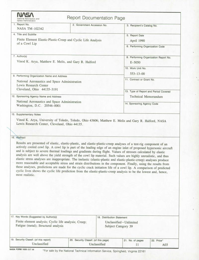
Results are presented of elastic, elastic-plastic, and elastic-plastic-creep analyses of a test-rig component of an actively cooled cowl lip. A cowl lip is part of the leading edge of an engine inlet of proposed hypersonic aircraft and is subject to severe thermal loadings and gradients during flight. Values of stresses calculated by elastic analysis are well above the yield strength of the cowl lip material. Such values are highly unrealistic, and thus elastic stress analyses are inappropriate. The inelastic (elastic-plastic and elastic-plastic-creep) analyses produce more reasonable and acceptable stress and strain distributions in the component. Finally, using the results from these analyses, predictions are made for the cyclic crack initiation life of a cowl lip. A comparison of predicted cyclic lives shows the cyclic life prediction from the elastic-plastic-creep analysis to be the lowest and, hence, most realistic.
17. Key Words (Suggested by Author(s)) 18. Distribution Statement
Finite element analysis; Cyclic life analysis; Creep; Unclassified—Unlimited Fatigue (metal); Structural analysis Subject Category 39
19. Security Classif. (of this report) 20. Secu rity Classif. (of this page) 21. No. of pages 22. Price
Unclassified Unclassified 11 A03NASA UflM lbZb OCT86
'For sale by the National Technical Information Service, Springfield, Virginia 22161

FOURTH CLASS MAIL II I ADDRESS CORRECTION REQUESTED 1E'1
MAt
iaF ees Pj National Aeronau1cs and Space Admn,sration NASA 451
National Aeronautics and Space Administration
Lewis Research Center Cleveland, Ohio 44135
Official Business Penalty for Private Use $300
NASA