Finite element analysis of couple effect of soil ...
9
J. Cent. South Univ. (2014) 21: 3656−3664 DOI: 10.1007/s11771-014-2348-y Finite element analysis of couple effect of soil displacement and axial load on single inclined pile WANG Li(王丽) 1 , ZHENG Gang(郑刚) 2 , OU Ruo-nan(欧若楠) 3 1. School of Civil and Safety Engineering, Dalian Jiaotong University, Dalian 116028, China; 2. Key Laboratory of Coast Civil Structure Safety of Ministry of Education (Tianjin University), Tianjin 300072, China; 3. Honors School, Harbin Institute of Technology, Harbin 150090, China © Central South University Press and Springer-Verlag Berlin Heidelberg 2014 Abstract: The couple effect of soil displacement and axial load on the single inclined pile in cases of surcharge load and uniform soil movement is discussed in detail with the methods of full-scale field tests and finite element method. Parametric analyses including the degree of inclination and the distance between soil and pile are carried out herein. When the displacement of soil on the left side and right side of a pile is identical, deformation of a vertical pile and an inclined pile is highly close in both cases of surcharge load and uniform soil movement. When the couple effect of soil displacement and axial load occurs, settlement of an inclined pile is greater than that of a vertical pile under the same axial load, and bearing capacity of an inclined pile is smaller than that of a vertical pile. This is quite different from the case when the inclined pile is not affected by soil displacement. For inclined piles, P−Δ effect of axial load would lead to a large increase in bending moment, however, for the vertical pile, P−Δ effect of axial load can be neglected. Although the direction of inclination of piles is reverse, deformation of piles caused by uniform soil movement is totally the same. For the inclined piles discussed herein, bending moment (−8 m to −17 m under the ground) relies heavily on uniform soil movement and does not change during the process of applying axial load. When the thickness of soil is less than the pile length, the greater the thickness of soil, the larger the bending moment at lower part of the inclined pile. When the thickness of soil is larger than the pile length, bending moment at lower part of the inclined pile is zero. Key words: couple effect; inclined pile; surcharge load; uniform soil movement; axial load 1 Introduction Effect of soil displacement on pile foundation nearby is of great importance in geotechnical projects such as tunneling, pit excavation, surcharge load, and slope engineering. Inclined piles are widely used in these projects due to the superior capability for resisting lateral load. At present, a series of researches on the bearing capacity of inclined pile were implemented. Based on physical model tests, vertical bearing capacity of pile foundation with the inclination degree of 0° to 12° was investigated [1]. The negative skin friction of single inclined pile and inclined pile group in viscous soil layer consolidated under surface load was studied [2]. Model tests were carried out to investigate the behavior of single-row and double-row contiguous retaining piles during the pit excavation process [3−4]. Field load tests and the finite element method were implemented to investigate the vertical bearing capacity of inclined pile [5−7]. According to the finite element analysis of the axial and lateral stiffness of inclined pile and vertical pile and the analysis of load sharing of pile group, the performance of battered pile foundation was discussed [8]. Behavior of single free-head model flexible vertical and batter piles under central inclined loads in two-layered soil was investigated [9]. Bearing capacity of inclined piles due to pit excavation was studied with the finite element method [10]. The characteristics of behavior of pile groups containing raked piles were examined [11]. Bearing capacity of inclined piles in the soft soil was studied with numerical method [12]. Investigation of the shaft resistance of single vertical and batter piles pushed into sand was conducted with experimental method [13]. Most previous researches were focused on the vertical bearing capacity of inclined pile. Only a little research presented the effect of soil displacement on inclined piles. However, the couple effect of soil displacement and axial load on the inclined pile has not yet been fully understood and well documented in literature. Foundation item: Project(51208071) supported by the National Natural Science Foundation of China; Project(2010CB732106) supported by the National Basic Research Program of China Received date: 2013−05−29; Accepted date: 2013−10−01 Corresponding author: WANG Li, Associate Professor, PhD; Tel.:+86−411−84105157; E-mail: [email protected]
Transcript of Finite element analysis of couple effect of soil ...
J. Cent. South Univ. (2014) 21: 3656−3664 DOI: 10.1007/s11771-014-2348-y
Finite element analysis of couple effect of soil displacement and axial load on single inclined pile
WANG Li(王丽)1, ZHENG Gang(郑刚)2, OU Ruo-nan(欧若楠)3
1. School of Civil and Safety Engineering, Dalian Jiaotong University, Dalian 116028, China;
2. Key Laboratory of Coast Civil Structure Safety of Ministry of Education (Tianjin University), Tianjin 300072, China; 3. Honors School, Harbin Institute of Technology, Harbin 150090, China
© Central South University Press and Springer-Verlag Berlin Heidelberg 2014
Abstract: The couple effect of soil displacement and axial load on the single inclined pile in cases of surcharge load and uniform soil movement is discussed in detail with the methods of full-scale field tests and finite element method. Parametric analyses including the degree of inclination and the distance between soil and pile are carried out herein. When the displacement of soil on the left side and right side of a pile is identical, deformation of a vertical pile and an inclined pile is highly close in both cases of surcharge load and uniform soil movement. When the couple effect of soil displacement and axial load occurs, settlement of an inclined pile is greater than that of a vertical pile under the same axial load, and bearing capacity of an inclined pile is smaller than that of a vertical pile. This is quite different from the case when the inclined pile is not affected by soil displacement. For inclined piles, P−Δ effect of axial load would lead to a large increase in bending moment, however, for the vertical pile, P−Δ effect of axial load can be neglected. Although the direction of inclination of piles is reverse, deformation of piles caused by uniform soil movement is totally the same. For the inclined piles discussed herein, bending moment (−8 m to −17 m under the ground) relies heavily on uniform soil movement and does not change during the process of applying axial load. When the thickness of soil is less than the pile length, the greater the thickness of soil, the larger the bending moment at lower part of the inclined pile. When the thickness of soil is larger than the pile length, bending moment at lower part of the inclined pile is zero. Key words: couple effect; inclined pile; surcharge load; uniform soil movement; axial load
1 Introduction
Effect of soil displacement on pile foundation nearby is of great importance in geotechnical projects such as tunneling, pit excavation, surcharge load, and slope engineering. Inclined piles are widely used in these projects due to the superior capability for resisting lateral load.
At present, a series of researches on the bearing capacity of inclined pile were implemented. Based on physical model tests, vertical bearing capacity of pile foundation with the inclination degree of 0° to 12° was investigated [1]. The negative skin friction of single inclined pile and inclined pile group in viscous soil layer consolidated under surface load was studied [2]. Model tests were carried out to investigate the behavior of single-row and double-row contiguous retaining piles during the pit excavation process [3−4]. Field load tests and the finite element method were implemented to investigate the vertical bearing capacity of inclined pile [5−7]. According to the finite element analysis of the
axial and lateral stiffness of inclined pile and vertical pile and the analysis of load sharing of pile group, the performance of battered pile foundation was discussed [8]. Behavior of single free-head model flexible vertical and batter piles under central inclined loads in two-layered soil was investigated [9]. Bearing capacity of inclined piles due to pit excavation was studied with the finite element method [10]. The characteristics of behavior of pile groups containing raked piles were examined [11]. Bearing capacity of inclined piles in the soft soil was studied with numerical method [12]. Investigation of the shaft resistance of single vertical and batter piles pushed into sand was conducted with experimental method [13].
Most previous researches were focused on the vertical bearing capacity of inclined pile. Only a little research presented the effect of soil displacement on inclined piles. However, the couple effect of soil displacement and axial load on the inclined pile has not yet been fully understood and well documented in literature.
Foundation item: Project(51208071) supported by the National Natural Science Foundation of China; Project(2010CB732106) supported by the National
Basic Research Program of China Received date: 2013−05−29; Accepted date: 2013−10−01 Corresponding author: WANG Li, Associate Professor, PhD; Tel.:+86−411−84105157; E-mail: [email protected]

J. Cent. South Univ. (2014) 21: 3656−3664
3657
2 Validation of finite element model
Full-scale field tests on inclined piles in Tianjin were modeled with the finite element method [5−7]. Results from the finite element model showed fine agreement with data collected from the field tests.
Based on the same finite element model [5−7], effect of soil displacement on the bearing capacity of single friction pile was discussed [14]. Results from the finite element model were consistent with those of the model tests [15−16].
The finite element model and parameters mentioned above provide a reliable way to study the behavior of inclined pile. The same finite element model and parameters are adopted in this work to investigate the couple effect of soil displacement and axial load on the inclined pile in the cases of surcharge load and uniform soil movement. Parameters of soil and inclined pile were described in detail in Refs. [5−7]. 3 Effect of surcharge load on single inclined
pile
Both the vertical pile and the inclined pile are 17 m in length and 0.5 m in diameter. Elastic modulus of 3×10⁴ MPa and Poisson ratio of 0.2 are adopted for the concrete pile. Pile inclines to the right with the degree of inclination θ of 2°, 4°, and 8° (see Fig. 1). Surcharge load p is imposed on the ground (10 m×20 m) 2 m away from the inclined pile.
The surcharge load p increases from 0 to 180 kPa step by step, and then axial loads applied on the inclined
Fig. 1 Pile and surcharge load: (a) Plane; (b) Section
pile increase. Curves of the axial load (Q) and settlement (s) at
pile head are shown in Fig. 2. Settlements of piles in Fig. 2 are caused only by axial loads, and those by surcharge load p are diminished.
Fig. 2 Q−s curves at pile head
Bearing capacities of the vertical pile, the inclined
piles with the degree of inclination θ of 2°, 4°, and 8° are 2480 kN, 2400 kN, 2400 kN, and 2237 kN, respectively.
Under the same axial load, settlement of vertical pile is the smallest, and settlement of the inclined pile (θ=8°) is slightly larger than that of others, and settlement of inclined piles (θ=2° and 4°) is very close to that of vertical pile.
Results from the field tests [5] and finite element analysis [5−7] showed that when the degree of inclination was no more than 4% (θ=2.29°), settlement of inclined piles was less than that of a vertical pile under the same axial load. This indicates that behavior of inclined piles changes when the couple effect of soil displacement and axial load occurs.
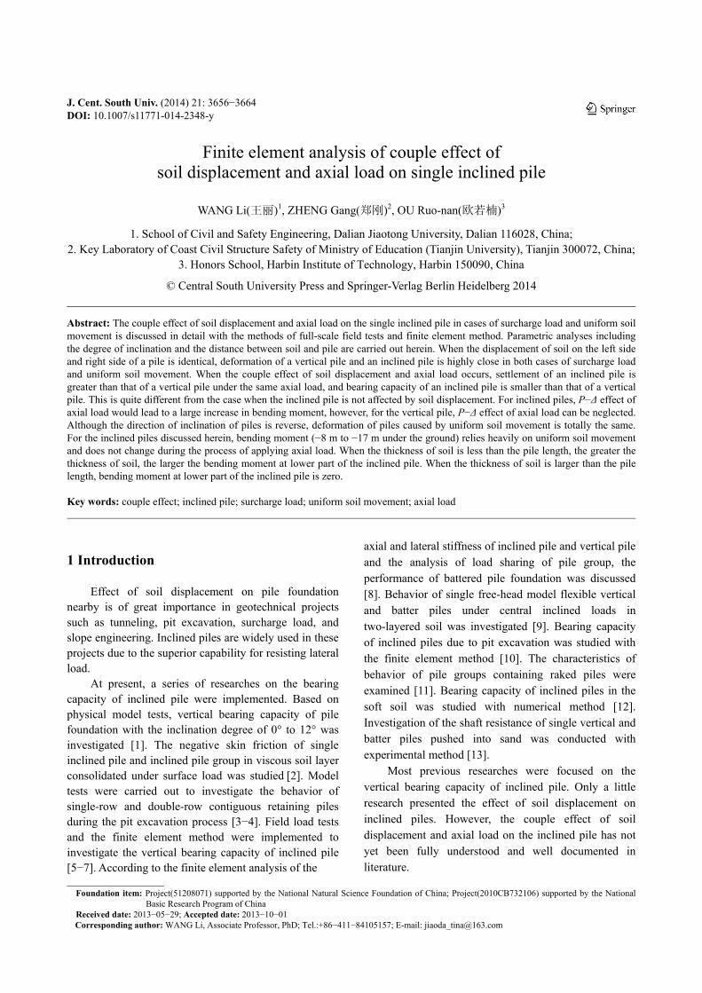
Lateral displacements of piles during the process of applying surcharge load and axial loads are shown in Fig. 3.
For the vertical pile, lateral displacement caused by surcharge load is about 90.66% of the total displacement, which means that P−Δ effect of axial load can be neglected. However, for the inclined piles, displacements (0 to −4 m under the ground) decrease during the period of applying axial load. The larger the degree of inclination, the greater the decrease in displacement.
Lateral displacements of piles caused by the surcharge load (p=180 kPa) are shown in Fig. 3(d). Displacements of inclined piles are highly close to that of the vertical pile.
Shaft resistances along piles during the period of applying axial loads are shown in Fig. 4.
Under the same axial load, shaft resistances (−5 m to −17 m under the ground) on the left side of inclined piles and vertical pile are very close. Shaft resistances (0 to −5 m under the ground) on the left side of inclined piles
J. Cent. South Univ. (2014) 21: 3656−3664
3658
Fig. 3 Lateral displacement of piles: (a) Vertical pile; (b) Inclined pile, θ=4°; (c) Inclined pile, θ=8°; (d) Comparison between vertical
pile and inclined piles
Fig. 4 Shaft resistances along piles: (a) Left side; (b) Right side
decrease on account of the deformation caused by axial loads.
Shaft resistance (−3 m to −11 m under the ground) on the right side of inclined pile (θ=8°) is smaller than that of other piles. Therefore, its bearing capacity is also smaller than that of others (see Fig. 2).
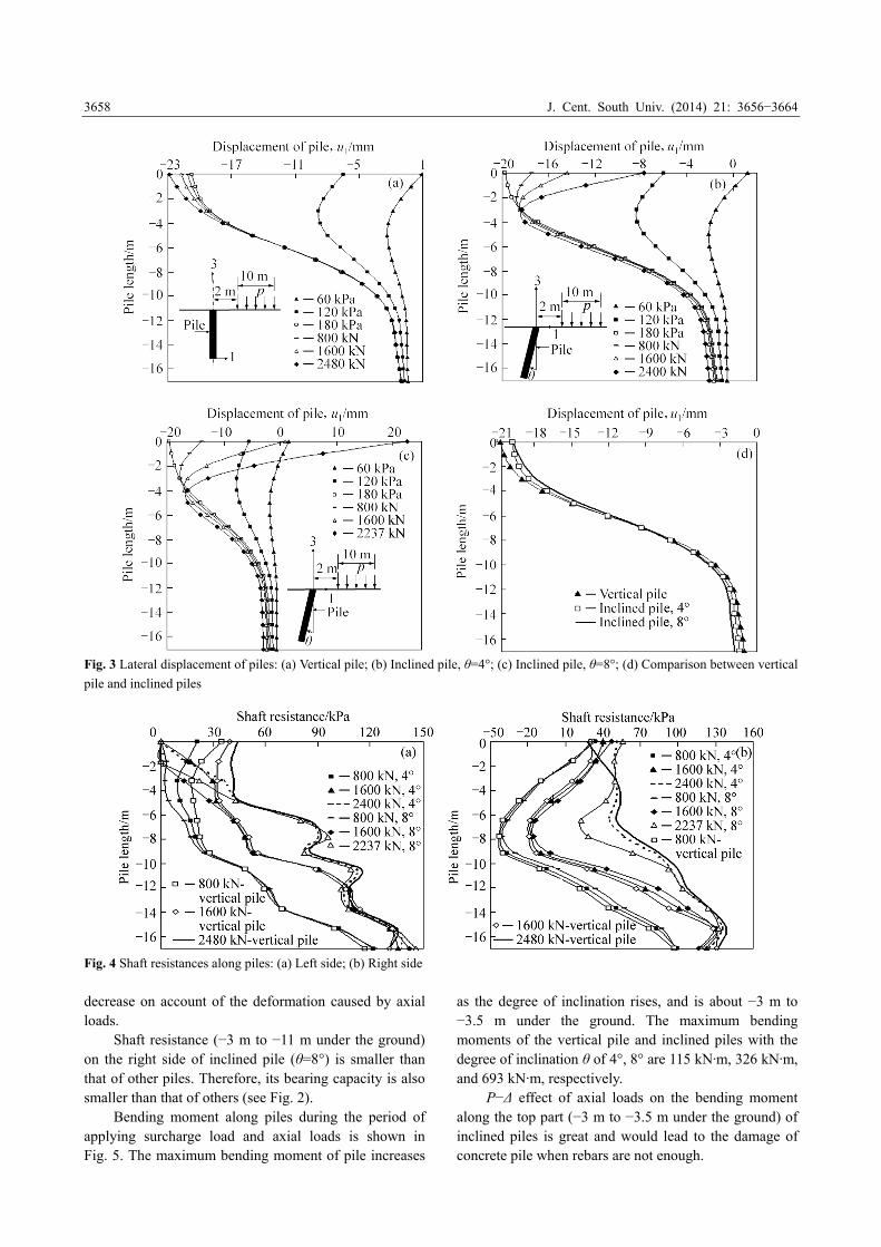
Bending moment along piles during the period of applying surcharge load and axial loads is shown in Fig. 5. The maximum bending moment of pile increases
as the degree of inclination rises, and is about −3 m to −3.5 m under the ground. The maximum bending moments of the vertical pile and inclined piles with the degree of inclination θ of 4°, 8° are 115 kN·m, 326 kN·m, and 693 kN·m, respectively.
P−Δ effect of axial loads on the bending moment along the top part (−3 m to −3.5 m under the ground) of inclined piles is great and would lead to the damage of concrete pile when rebars are not enough.
J. Cent. South Univ. (2014) 21: 3656−3664
3659
Fig. 5 Bending moments along piles: (a) Vertical pile;
(b) Inclined pile, θ=4°; (c) Inclined pile, θ=8°
4 Effect of uniform soil movement on single inclined pile
The concrete pile is 17 m long and the pile diameter
is 0.5 m. Elastic modulus of 3×10⁴ MPa and Poisson ratio of 0.2 are adopted for the concrete pile. Pile inclines to the left (see Fig. 6).
Soil with the volume of 20 m×10 m×H on both sides of the pile undergoes the uniform soil movement of 100 mm in the direction of coordinate 1 (Fig. 6), and then axial loads at pile head increase.
Cases of the effect of uniform soil movement on single pile discussed herein are summarized in Table 1.
Fig. 6 Pile and uniform soil movement: (a) Plane; (b) Section
(rectangle); (c) Section (triangle)
Table 1 Cases of uniform soil movement
CaseInclined
angle, θ/(°)
Distance between
soil and pile, D/m
Thickness of
soil, H/m
1 0 10 10.5
2 2 10 10.5
3 4 10 10.5
4 8 10 10.5
5 8 5 10.5
6 -8 5 10.5
7 8 5 6.5
8 8 5 21.5
9 8 5 10.5 (triangle)
The degree of inclination θ=−8° in the case 6 indicates that pile inclines to the right. Soil section in the case 9 is triangle (see Fig. 6(c)), and soil section of the other cases is rectangle (see Fig. 6(b)). 4.1 Comparison of results from Cases 1 to 4
Curves of the axial load (Q) and settlement (s) of piles in the cases of 1 to 4 are shown in Fig. 7. Settlements
J. Cent. South Univ. (2014) 21: 3656−3664
3660
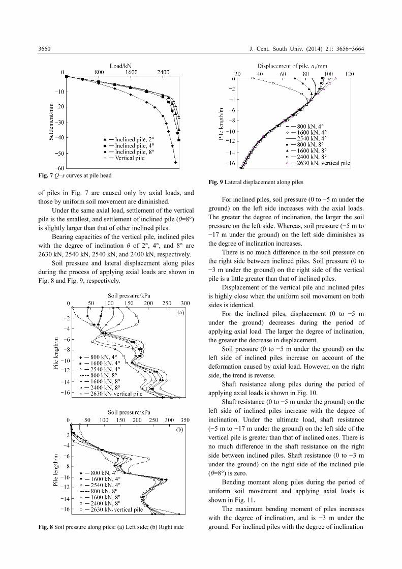
Fig. 7 Q−s curves at pile head
of piles in Fig. 7 are caused only by axial loads, and those by uniform soil movement are diminished.
Under the same axial load, settlement of the vertical pile is the smallest, and settlement of inclined pile (θ=8°) is slightly larger than that of other inclined piles.
Bearing capacities of the vertical pile, inclined piles with the degree of inclination θ of 2°, 4°, and 8° are 2630 kN, 2540 kN, 2540 kN, and 2400 kN, respectively.
Soil pressure and lateral displacement along piles during the process of applying axial loads are shown in Fig. 8 and Fig. 9, respectively.
Fig. 8 Soil pressure along piles: (a) Left side; (b) Right side
Fig. 9 Lateral displacement along piles
For inclined piles, soil pressure (0 to −5 m under the ground) on the left side increases with the axial loads. The greater the degree of inclination, the larger the soil pressure on the left side. Whereas, soil pressure (−5 m to −17 m under the ground) on the left side diminishes as the degree of inclination increases.
There is no much difference in the soil pressure on the right side between inclined piles. Soil pressure (0 to −3 m under the ground) on the right side of the vertical pile is a little greater than that of inclined piles.
Displacement of the vertical pile and inclined piles is highly close when the uniform soil movement on both sides is identical.
For the inclined piles, displacement (0 to −5 m under the ground) decreases during the period of applying axial load. The larger the degree of inclination, the greater the decrease in displacement.
Soil pressure (0 to −5 m under the ground) on the left side of inclined piles increase on account of the deformation caused by axial load. However, on the right side, the trend is reverse.
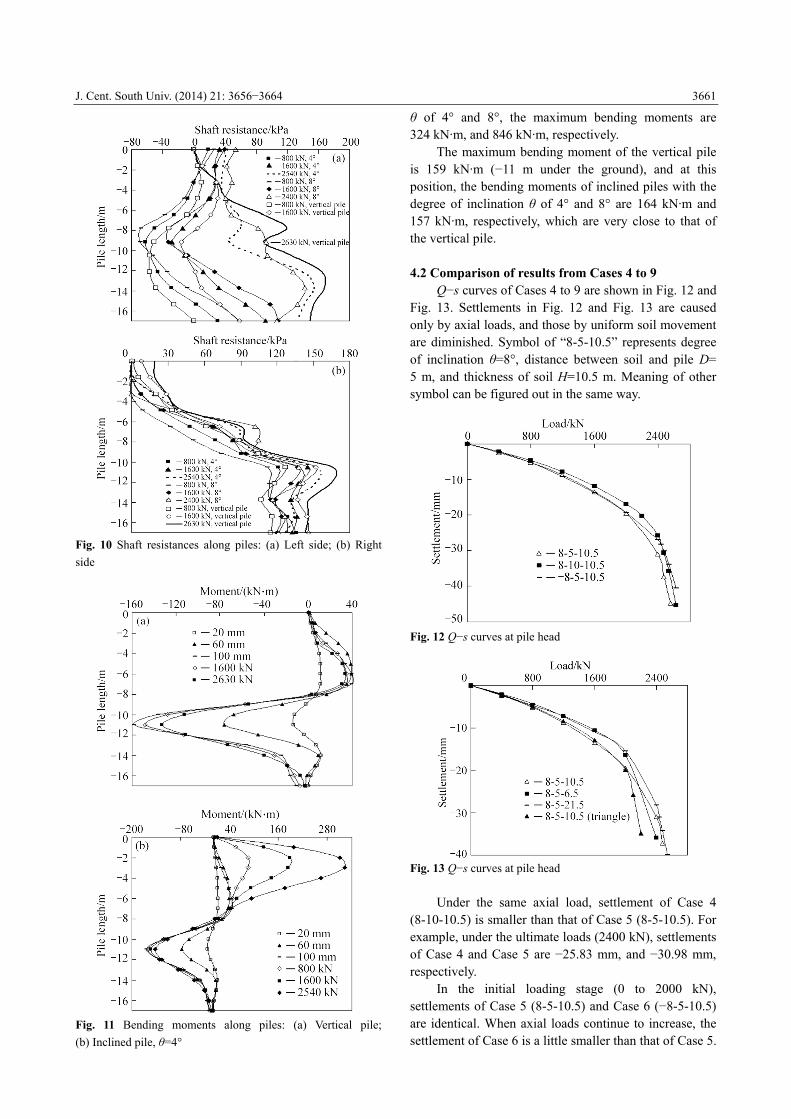
Shaft resistance along piles during the period of applying axial loads is shown in Fig. 10.
Shaft resistance (0 to −5 m under the ground) on the left side of inclined piles increase with the degree of inclination. Under the ultimate load, shaft resistance (−5 m to −17 m under the ground) on the left side of the vertical pile is greater than that of inclined ones. There is no much difference in the shaft resistance on the right side between inclined piles. Shaft resistance (0 to −3 m under the ground) on the right side of the inclined pile (θ=8°) is zero.
Bending moment along piles during the period of uniform soil movement and applying axial loads is shown in Fig. 11.
The maximum bending moment of piles increases with the degree of inclination, and is −3 m under the ground. For inclined piles with the degree of inclination
J. Cent. South Univ. (2014) 21: 3656−3664
3661
Fig. 10 Shaft resistances along piles: (a) Left side; (b) Right
side
Fig. 11 Bending moments along piles: (a) Vertical pile;
(b) Inclined pile, θ=4°
θ of 4° and 8°, the maximum bending moments are 324 kN·m, and 846 kN·m, respectively.
The maximum bending moment of the vertical pile is 159 kN·m (−11 m under the ground), and at this position, the bending moments of inclined piles with the degree of inclination θ of 4° and 8° are 164 kN·m and 157 kN·m, respectively, which are very close to that of the vertical pile. 4.2 Comparison of results from Cases 4 to 9
Q−s curves of Cases 4 to 9 are shown in Fig. 12 and Fig. 13. Settlements in Fig. 12 and Fig. 13 are caused only by axial loads, and those by uniform soil movement are diminished. Symbol of “8-5-10.5” represents degree of inclination θ=8°, distance between soil and pile D= 5 m, and thickness of soil H=10.5 m. Meaning of other symbol can be figured out in the same way.
Fig. 12 Q−s curves at pile head
Fig. 13 Q−s curves at pile head
Under the same axial load, settlement of Case 4
(8-10-10.5) is smaller than that of Case 5 (8-5-10.5). For example, under the ultimate loads (2400 kN), settlements of Case 4 and Case 5 are −25.83 mm, and −30.98 mm, respectively.
In the initial loading stage (0 to 2000 kN), settlements of Case 5 (8-5-10.5) and Case 6 (−8-5-10.5) are identical. When axial loads continue to increase, the settlement of Case 6 is a little smaller than that of Case 5.

J. Cent. South Univ. (2014) 21: 3656−3664
3662
For instance, under the ultimate loads (2400 kN), settlements of Case 5 (8-5-10.5) and Case 6 (−8-5-10.5) are −30.98 mm, and −26.94 mm, respectively.
When the soil section is rectangle, settlements of Case 7 (8-5-6.5) and Case 8 (8-5-21.5) are very close, and are a little smaller than that of Case 5 (8-5-10.5). For example, under the axial loads (2000 kN), settlements of Case 5, Case 7, and Case 8 are −19.55 mm, −16.47 mm, and −15.51 mm, respectively.
In the initial loading stage (0 to 2000 kN), settlements of Case 5 (8-5-10.5) and Case 9 (8-5-10.5 (triangle)) are identical. When axial loads continue to increase, settlement of Case 9 increases apparently. On the left side of the inclined pile, degree of soil compression caused by movement of soil with triangle section is certainly low compared with soil of rectangular section.
During the period of uniform soil movement and applying axial loads, lateral displacements of piles of Cases 4 to 6 are shown in Fig. 14.
When uniform soil movement on both sides of the pile is identical, deformation of pile varies with the distance between soil and pile. As is shown in Fig. 14, pile of Case 4 (8-10-10.5) inclines. While, piles (0 to −7 m under the ground) move uniformly in Case 5 (8-5-10.5) and Case 6 (−8-5-10.5), and the displacement
is nearly the same as that of soil on both sides. When axial loads increase from 0 to 2400 kN,
changes in displacement at pile head in Case 5 (8-5-10.5), Case 6 (−8-5-10.5), and Case 4 (8-10-10.5) are 68.9, 80, and 70 mm, respectively.
When the displacement of soil on both sides of the pile is identical, deformations of piles in Case 5 (8-5-10.5) and Case 6 (−8-5-10.5) are totally the same (Fig. 14(d)).
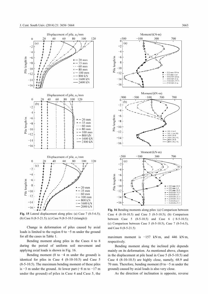
During the period of uniform soil movement and applying axial loads, lateral displacements of piles of Cases 7 to 9 are shown in Fig. 15.
When uniform soil movement on both sides of the pile is identical, deformation of the pile varies with the thickness of soil.
As is shown in Fig. 15(b), deformation along the pile in Case 8 (8-5-21.5) is totally identical to that of soil on both sides. Pile in Case 7 (8-5-6.5) inclines with the displacement of 117 mm at pile head, a little greater than that of soil (100 mm).
In the initial loading stage (0 to 2400 kN), changes in the displacement at pile head in Case 5 (8-5-10.5), Case 7 (8-5-6.5), and Case 8 (8-5-21.5) are 68.9, 68.7, and 68.2 mm, respectively.
Pile in Case 9 (8-5-6.5(triangle)) inclines with the displacement of 107 mm at pile head.
Fig. 14 Lateral displacement along piles: (a) Case 4 (8-10-10.5); (b) Case 5 (8-5-10.5); (c) Case 6 (−8-5-10.5); (d) Comparison
between Case 5 (8-5-10.5) and Case 6 (−8-5-10.5)
J. Cent. South Univ. (2014) 21: 3656−3664
3663
Fig. 15 Lateral displacement along piles: (a) Case 7 (8-5-6.5);
(b) Case 8 (8-5-21.5); (c) Case 9 (8-5-10.5 (triangle))
Change in deformation of piles caused by axial loads is limited to the region 0 to −5 m under the ground for all the cases in Table 1.
Bending moment along piles in the Cases 4 to 8 during the period of uniform soil movement and applying axial loads is shown in Fig. 16.
Bending moment (0 to −4 m under the ground) is identical for piles in Case 4 (8-10-10.5) and Case 5 (8-5-10.5). The maximum bending moment of these piles is −3 m under the ground. At lower part (−8 m to −17 m under the ground) of piles in Case 4 and Case 5, the
Fig. 16 Bending moments along piles: (a) Comparison between
Case 4 (8-10-10.5) and Case 5 (8-5-10.5); (b) Comparison
between Case 5 (8-5-10.5) and Case 6 (−8-5-10.5);
(c) Comparison between Case 5 (8-5-10.5), Case 7 (8-5-6.5),
and Case 8 (8-5-21.5)
maximum moment is −157 kN·m, and 446 kN·m, respectively.
Bending moment along the inclined pile depends mainly on its deformation. As mentioned above, changes in the displacement at pile head in Case 5 (8-5-10.5) and Case 4 (8-10-10.5) are highly close, namely, 68.9 and 70 mm. Therefore, bending moment (0 to −5 m under the ground) caused by axial loads is also very close.
As the direction of inclination is opposite, reverse
J. Cent. South Univ. (2014) 21: 3656−3664
3664
flexure deformation occurs in Case 5 (8-5-10.5) and Case 6 (−8-5-10.5) when axial loads are imposed. The maximum bending moments of Case 5 and Case 6 are 839 kN·m and 795 kN·m, respectively.
As the pile in Case 8 (8-5-21.5) moves uniformly during the period of uniform soil movement, there is no flexure deformation for the pile in Case 8. As a result, bending moment of the pile in Case 8 (−8 m to −17 m under the ground) is zero.
The maximum bending moments of piles (−8 m to −17 m under the ground) in Case 5 (8-5-10.5) and Case 7 (8-5-6.5) are 439 kN·m and 283 kN·m, respectively, depending on the deformation caused by uniform soil movement.
For all the piles in Table 1, bending moment (−8 m to −17 m under the ground) depends entirely on the uniform soil movement and does not change during the process of applying axial load. Bending moment (0 to −5 m under the ground) depends totally on axial loads, and the difference in bending moment between these piles is small as change in displacement caused by axial loads is similar. The maximum bending moment of these piles is −3 m under the ground. 5 Conclusions
1) When the displacement of soil on the left side and right side of a pile is identical, deformation of a vertical pile and an inclined pile is highly close in both cases of surcharge load and uniform soil movement.
2) When the couple effect of soil displacement and axial load occurs, settlement of an inclined pile is greater than that of a vertical pile under the same axial load, and bearing capacity of an inclined pile is smaller than that of a vertical pile. This is quite different from the case when the inclined pile is not affected by soil displacement.
3) For inclined piles, P−Δ effect of axial load would lead to a large increase in bending moment, however, for the vertical pile, P−Δ effect of axial load can be neglected.
4) Although the direction of inclination of piles is reverse, deformation of piles caused by uniform soil movement is totally the same.
5) For the inclined piles discussed herein, bending moment (−8 m to −17 m under the ground) relies heavily on uniform soil movement and does not change during the process of applying axial load. Bending moment (0 to −5 m under the ground) depends on axial loads and the difference in bending moment of inclined piles is small as changes in displacement of piles caused by axial loads are quite close.
6) When the thickness of soil is less than the pile length, the greater the thickness of soil, the larger the bending moment at lower part of the inclined pile. When
the thickness of soil is larger than the pile length, bending moment at lower part of the inclined pile is zero. References [1] LI Long-qi, LUO Shu-xue. A simulation test study of vertical bearing
capacity of inclined pile foundation in inhomogeneous strata [J].
Rock and Soil Mechanics, 2012, 33(5): 1300−1305. (in Chinese)
[2] KONG Gang-qiang, YANG Qing, ZHENG Peng-yi, LUAN Mao-tian.
Model tests on negative skin friction for inclined pile considering
time effect: Load transfer and bearing capacity of inclined pile under
vertical load [J]. Chinese Journal of Geotechnical Engineering, 2009,
31(4): 617−621. (in Chinese)
[3] ZHENG Gang, BAI Ruo-xu. Behaviors study of inclined single row
contiguous retaining piles under horizontal force [J]. Chinese Journal
of Geotechnical Engineering, 2010, 32(Supp 1): 39−45. (in Chinese)
[4] XU Yuan, ZHENG Gang, LU Ping. Behaviors of double-row
contiguous retaining piles with raking front-row piles under
horizontal loads [J]. Chinese Journal of Geotechnical Engineering,
2010, 32(Supp.1): 93−98. (in Chinese)
[5] ZHENG Gang, WANG Li. Load transfer and bearing capacity of
inclined pile under vertical load [J]. Chinese Journal of Geotechnical
Engineering, 2008, 30(3): 323−330. (in Chinese)
[6] ZHENG Gang, WANG Li. Research on vertical bearing capacity of
partially inclined pile with finite element method, 2009, 30(11):
3533−3538. (in Chinese)
[7] ZHENG Gang, LI Shuai, DU Yi-ming, ZHANG Xiao-shuang.
Bearing capacity behaviors of inclined pile under vertical load [J].
Journal of Tianjin University, 2012, 45(7): 567−576. (in Chinese)
[8] WANG Yun-Gang, ZHANG Guang, HU Qi. Study of force
characteristics of battered pile foundation [J]. Rock and Soil
Mechanics, 2011, 32(7): 2184−2190. (in Chinese).
[9] MEYERHOF G G, YALCIN A S. Behaviour of flexible batter piles
under inclined loads in layered soil [J]. Canadian Geotechnical
Journal, 1993, 30: 247−256
[10] YANG Bao-zhu, WANG Li, ZHENG Gang. Analysis on bearing
capacity of inclined piles due to adjacent excavation by use of finite
element method [J]. Chinese Journal of Geotechnical Engineering,
2008, 30(supp.): 144−150. (in Chinese)
[11] H G POULOS. Raked piles-virtues and drawbacks [J]. Journal of
Geotechnical and Geoenvironmental Engineering, 2006, 132(6):
795−803.
[12] SU Zi-jiang, LUO Shu-xue, KANG Yin. Numerical analysis of
bearing capacity of inclined piles in the soft soil [J]. Geotechnical
Engineering and Underground Engineering, 2008, 28(5): 75−76. (in
Chinese)
[13] A HANNA, T Q NGUYEN. Shaft resistance of single verticaland
batter piles driven in sand [J]. Journal of Geotechnical and
Geoenvironmental Engineering, 2003, 129(7): 601−607.
[14] WANG Li, ZHENG Gang, OU Ruo-nan. Finite element analysis of
effect of soil displacement on bearing capacity of single friction pile
[J]. Journal of Central South University, 2014, 21: 2051−2058.
[15] GUO W D, GHEE E H. Model tests on single piles in sand subjected
to lateral soil movement [J]. Proceedings of the 18th Australasian
Conference on the Mechanics of Structures and Materials, 2004, 2:
997−1003.
[16] GUO W D, GHEE E H. Behavior of axially loaded pile groups
subjected to lateral soil movement [J]. Foundation Analysis and
Design, 2006, 174−181.
(Edited by HE Yun-bin)