FINITE ELEMENT ANALYSIS OF 3D REINFORCED ...umpir.ump.edu.my/12238/1/FKASA - MUHAMMAD ADIB BIN...
24
FINITE ELEMENT ANALYSIS OF 3D REINFORCED CONCRETE FRAME USING ANSYS MUHAMMAD ADIB BIN EMBONG Report submitted in partial fulfillment of the requirements for the award of degree of B.Eng. (Hons.) Civil Engineering Faculty of Civil Engineering & Earth Resources UNIVERSITI MALAYSIA PAHANG JUNE 2015
Transcript of FINITE ELEMENT ANALYSIS OF 3D REINFORCED ...umpir.ump.edu.my/12238/1/FKASA - MUHAMMAD ADIB BIN...
FINITE ELEMENT ANALYSIS OF 3D REINFORCED CONCRETE FRAME USING
ANSYS
MUHAMMAD ADIB BIN EMBONG
Report submitted in partial fulfillment of the requirements
for the award of degree of
B.Eng. (Hons.) Civil Engineering
Faculty of Civil Engineering & Earth Resources
UNIVERSITI MALAYSIA PAHANG
JUNE 2015
vi
ABSTRACT
In this research, 3D reinforced concrete frame structure is analyzed by using
Probabilistic Method with ANSYS and checked by Finite Element Method and
Eurocode 3. This analysis is to determine the behavior of the reinforced concrete frame
and to study about the probabilistic response analysis and input sensitivities of the
reinforced concrete frame. Nowadays, reinforced concrete frame is widely used in many
high rise building construction include shopping mall, condominium, apartment and
tower. The material used in this analysis is 30N/mm2 of concrete and 500N/mm
2 of
reinforced steel bar. The material and geometry of the reinforced concrete frame was
satisfied for this research since it passed all the design criteria in designing for axial
bending, shear & torsion and cracking. The numerical results show very good
agreement with manual calculation results. From the results of simulation, we get to
know the real behavior of the structure under the applied loads. In probabilistic analysis,
we get the results of cumulative distribution function, histogram plot, sensitivity plot
and simple history plot by 10000 times of simulation for any input and output.

vii
ABSTRACT
Dalam kajian ini kerangka konkrit bertetulang 3D telah dianalisis menggunakan teknik
kebarangkalian dengan ANSYS dan disemak menggunakan Eurocode 3. Kajian ini
bertujuan untuk menentukan tingkah laku kerangka konkrit bertetulang dan mengkaji
kebarangkalian berdasarkan sensitiviti input kerangka konkrit bertetulang. Kini,
kerangka konkrit bertetulang banyak digunakan dalam pembinaan bangunan yang tinggi
seperti pusat membeli belah, kondominium, apartmen, dan menara. Antara bahan yang
digunakan dalam kerangka konkrit bertetulang ialah konkrit gred 30N/mm2 dan tetulang
gred 500N/mm2. Bahan-bahan serta reka bentuk kerangka tulang bertetulang memenuhi
keperluan untuk kajian kerana melepasi kesemua ujian reka bentuk untuk lenturan, ricih
dan kilasan serta keretakan. Berdasarkan keputusan berangka dan pengiraan manual,
kedua duanya menunjukkan hasil yang baik dan memuaskan. Dari hasil simulasi, kita
dapat mengenali tingkah laku sebenar struktur apabila beban dikenakan. Dalam analisis
kebarangkalian, kita akan mendapat hasil fungsi kumulatif pengedaran, histogram plot,
plot sensitiviti dan sejarah plot mudah oleh 10000 kali simulasi dari segi input dan
output.
viii
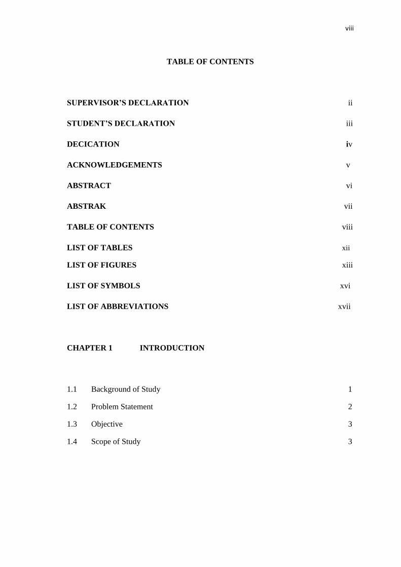
TABLE OF CONTENTS
SUPERVISOR’S DECLARATION ii
STUDENT’S DECLARATION iii
DECICATION iv
ACKNOWLEDGEMENTS v
ABSTRACT vi
ABSTRAK vii
TABLE OF CONTENTS viii
LIST OF TABLES xii
LIST OF FIGURES xiii
LIST OF SYMBOLS xvi
LIST OF ABBREVIATIONS xvii
CHAPTER 1 INTRODUCTION
1.1 Background of Study 1
1.2 Problem Statement 2
1.3 Objective 3
1.4 Scope of Study 3

ix
CHAPTER 2 LITERATURE REVIEW
2.1 Introduction 4
2.2 Reinforced Concrete Frame Structure 4
2.3 Advantages of Concrete Structure 5
2.4 Finite Element Method (FEM) 6
2.5 Load on Frame Structure 7
2.5.1 Static Force 7
2.5.2 Wind Load 8
2.5.3 Earthquake 9
CHAPTER 3 METHODOLOGY
3.1 Introduction 10
3.2 Design Process 11
3.2.1 Preprocessing Phase 11
3.2.1.1 Enter the title 12
3.2.1.2 Set code and unit 12
3.2.1.3 Define Material 14
3.2.1.4 Define the Type of Material 16
3.2.1.5 Define Concrete Cross Section 16
3.2.1.6 Beam & Shell Properties 18
3.2.1.7 Create Keypoint 19
3.2.1.8 Form Line 21
3.2.1.9 Meshing 21
3.2.2 Solution Phase 22
3.2.2.1 Apply Displacement 22
x
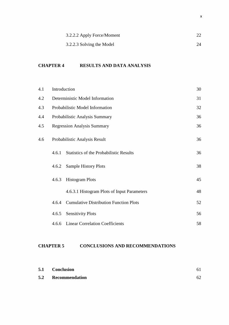
3.2.2.2 Apply Force/Moment 22
3.2.2.3 Solving the Model 24
CHAPTER 4 RESULTS AND DATA ANALYSIS
4.1 Introduction 30
4.2 Deterministic Model Information 31
4.3 Probabilistic Model Information 32
4.4 Probabilistic Analysis Summary 36
4.5 Regression Analysis Summary 36
4.6 Probabilistic Analysis Result 36
4.6.1 Statistics of the Probabilistic Results 36
4.6.2 Sample History Plots 38
4.6.3 Histogram Plots 45
4.6.3.1 Histogram Plots of Input Parameters 48
4.6.4 Cumulative Distribution Function Plots 52
4.6.5 Sensitivity Plots 56
4.6.6 Linear Correlation Coefficients 58
CHAPTER 5 CONCLUSIONS AND RECOMMENDATIONS
5.1 Conclusion 61
5.2 Recommendation 62
xi
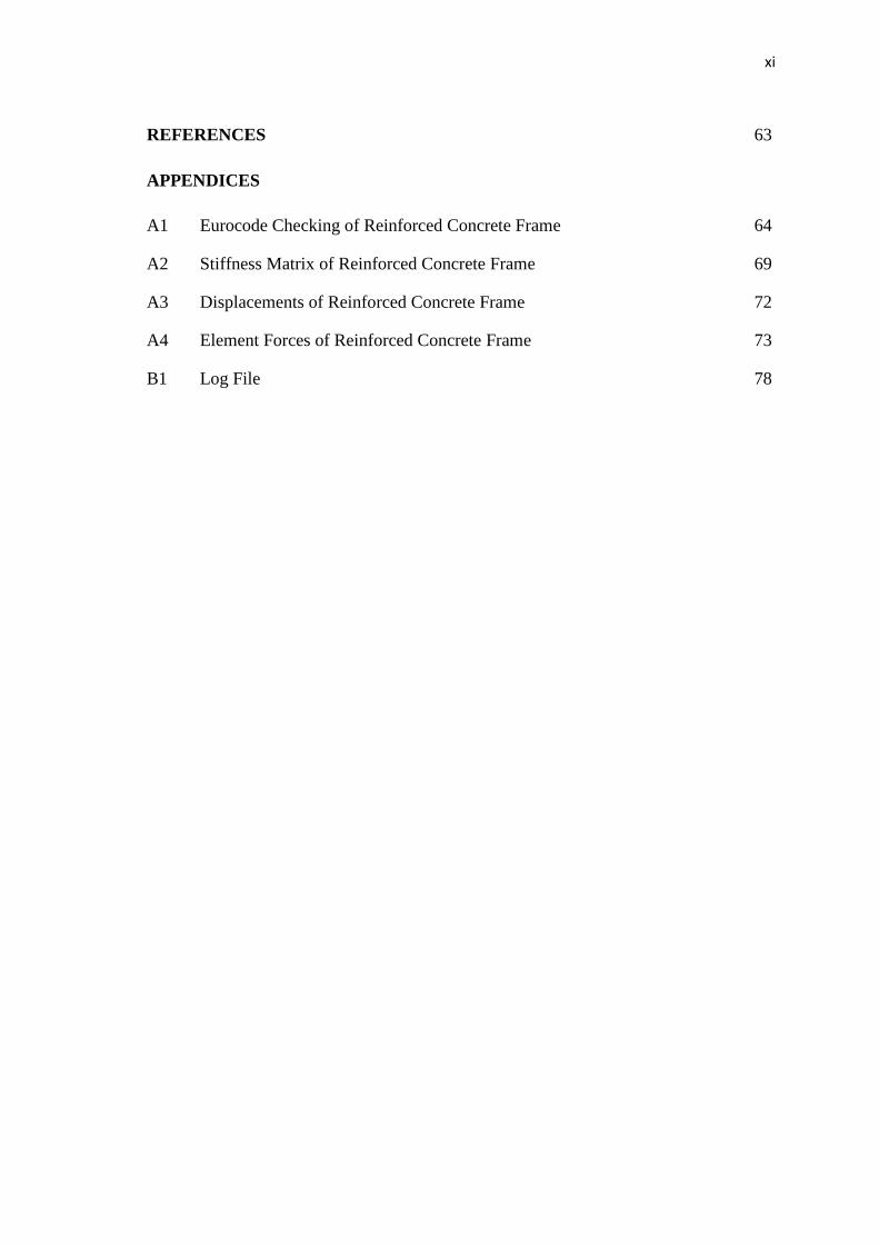
REFERENCES 63
APPENDICES
A1 Eurocode Checking of Reinforced Concrete Frame 64
A2 Stiffness Matrix of Reinforced Concrete Frame 69
A3 Displacements of Reinforced Concrete Frame 72
A4 Element Forces of Reinforced Concrete Frame 73
B1 Log File 78
xii
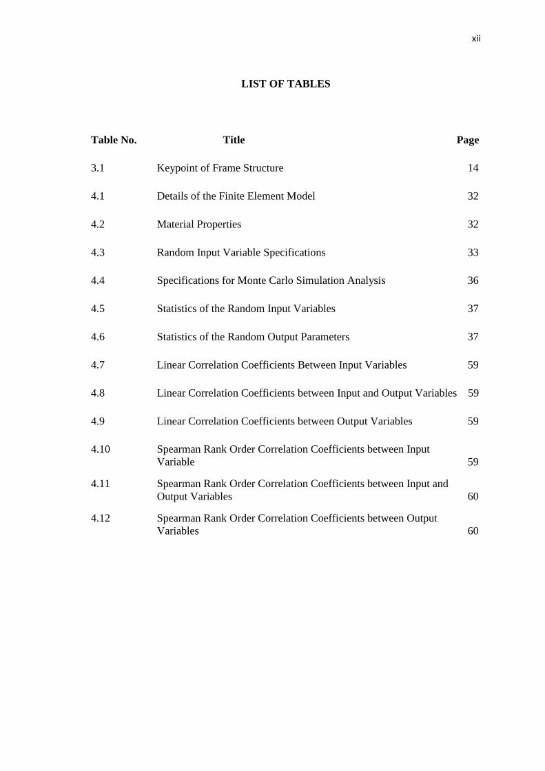
LIST OF TABLES
Table No. Title Page
3.1 Keypoint of Frame Structure 14
4.1 Details of the Finite Element Model 32
4.2 Material Properties 32
4.3 Random Input Variable Specifications 33
4.4 Specifications for Monte Carlo Simulation Analysis 36
4.5 Statistics of the Random Input Variables 37
4.6 Statistics of the Random Output Parameters 37
4.7 Linear Correlation Coefficients Between Input Variables 59
4.8 Linear Correlation Coefficients between Input and Output Variables 59
4.9 Linear Correlation Coefficients between Output Variables 59
4.10 Spearman Rank Order Correlation Coefficients between Input
Variable 59
4.11 Spearman Rank Order Correlation Coefficients between Input and
Output Variables 60
4.12 Spearman Rank Order Correlation Coefficients between Output
Variables 60
xiii
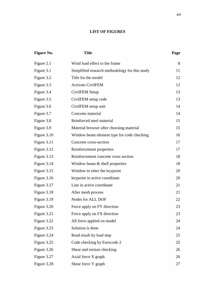
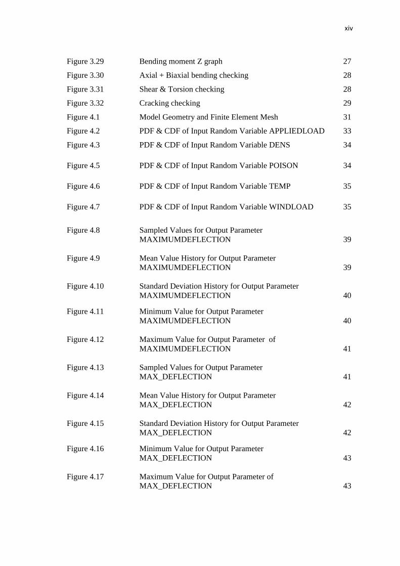
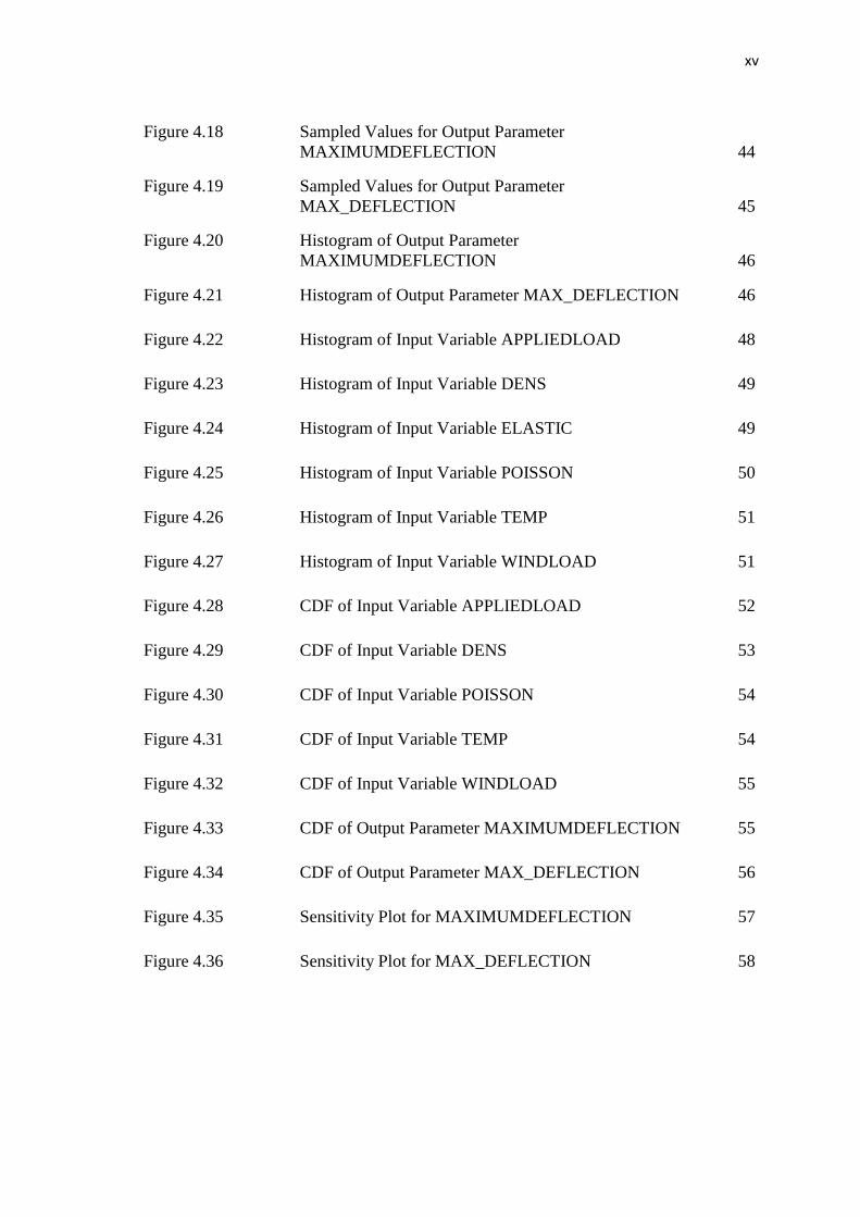
LIST OF FIGURES
Figure No. Title Page
Figure 2.1 Wind load effect to the frame 8
Figure 3.1 Simplified research methodology for this study 11
Figure 3.2 Title for the model 12
Figure 3.3 Activate CivilFEM 12
Figure 3.4 CivilFEM Setup 13
Figure 3.5 CivilFEM setup code 13
Figure 3.6 CivilFEM setup unit 14
Figure 3.7 Concrete material 14
Figure 3.8 Reinforced steel material 15
Figure 3.9 Material browser after choosing material 15
Figure 3.10 Window beam element type for code checking 16
Figure 3.11 Concrete cross-section 17
Figure 3.12 Reinforcement properties 17
Figure 3.13 Reinforcement concrete cross section 18
Figure 3.14 Window beam & shell properties 18
Figure 3.15 Window to enter the keypoint 20
Figure 3.16 keypoint in active coordinate 20
Figure 3.17 Line in active coordinate 21
Figure 3.18 After mesh process 21
Figure 3.19 Nodes for ALL DOF 22
Figure 3.20 Force apply on FY direction 23
Figure 3.21 Force apply on FX direction 23
Figure 3.22 All force applied on model 24
Figure 3.23 Solution is done 24
Figure 3.24 Read result by load step 25
Figure 3.25 Code checking by Eurocode 2 25
Figure 3.26 Shear and torsion checking 26
Figure 3.27 Axial force X graph 26
Figure 3.28 Shear force Y graph 27
xiv
Figure 3.29 Bending moment Z graph 27
Figure 3.30 Axial + Biaxial bending checking 28
Figure 3.31 Shear & Torsion checking 28
Figure 3.32 Cracking checking 29
Figure 4.1 Model Geometry and Finite Element Mesh 31
Figure 4.2 PDF & CDF of Input Random Variable APPLIEDLOAD 33
Figure 4.3 PDF & CDF of Input Random Variable DENS 34
Figure 4.5 PDF & CDF of Input Random Variable POISON 34
Figure 4.6 PDF & CDF of Input Random Variable TEMP 35
Figure 4.7 PDF & CDF of Input Random Variable WINDLOAD 35
Figure 4.8 Sampled Values for Output Parameter
MAXIMUMDEFLECTION 39
Figure 4.9 Mean Value History for Output Parameter
MAXIMUMDEFLECTION 39
Figure 4.10 Standard Deviation History for Output Parameter
MAXIMUMDEFLECTION 40
Figure 4.11 Minimum Value for Output Parameter
MAXIMUMDEFLECTION 40
Figure 4.12 Maximum Value for Output Parameter of
MAXIMUMDEFLECTION 41
Figure 4.13 Sampled Values for Output Parameter
MAX_DEFLECTION 41
Figure 4.14 Mean Value History for Output Parameter
MAX_DEFLECTION 42
Figure 4.15 Standard Deviation History for Output Parameter
MAX_DEFLECTION 42
Figure 4.16 Minimum Value for Output Parameter
MAX_DEFLECTION 43
Figure 4.17 Maximum Value for Output Parameter of
MAX_DEFLECTION 43
xv
Figure 4.18 Sampled Values for Output Parameter
MAXIMUMDEFLECTION 44
Figure 4.19 Sampled Values for Output Parameter
MAX_DEFLECTION 45
Figure 4.20 Histogram of Output Parameter
MAXIMUMDEFLECTION 46
Figure 4.21 Histogram of Output Parameter MAX_DEFLECTION 46
Figure 4.22 Histogram of Input Variable APPLIEDLOAD 48
Figure 4.23 Histogram of Input Variable DENS 49
Figure 4.24 Histogram of Input Variable ELASTIC 49
Figure 4.25 Histogram of Input Variable POISSON 50
Figure 4.26 Histogram of Input Variable TEMP 51
Figure 4.27 Histogram of Input Variable WINDLOAD 51
Figure 4.28 CDF of Input Variable APPLIEDLOAD 52
Figure 4.29 CDF of Input Variable DENS 53
Figure 4.30 CDF of Input Variable POISSON 54
Figure 4.31 CDF of Input Variable TEMP 54
Figure 4.32 CDF of Input Variable WINDLOAD 55
Figure 4.33 CDF of Output Parameter MAXIMUMDEFLECTION 55
Figure 4.34 CDF of Output Parameter MAX_DEFLECTION 56
Figure 4.35 Sensitivity Plot for MAXIMUMDEFLECTION 57
Figure 4.36 Sensitivity Plot for MAX_DEFLECTION 58
xvi
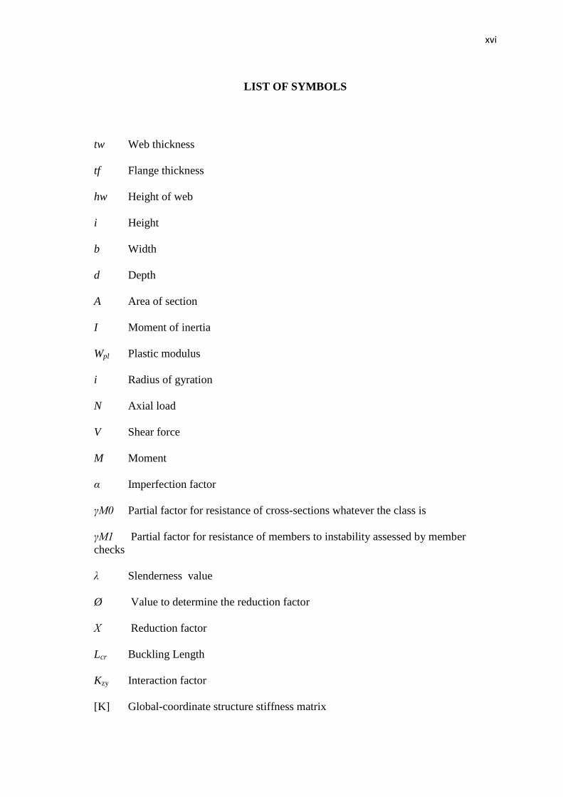
LIST OF SYMBOLS
tw Web thickness
tf Flange thickness
hw Height of web
i Height
b Width
d Depth
A Area of section
I Moment of inertia
Wpl
Plastic modulus
i Radius of gyration
N Axial load
V Shear force
M Moment
α Imperfection factor
γM0 Partial factor for resistance of cross-sections whatever the class is
γM1 Partial factor for resistance of members to instability assessed by member
checks
λ Slenderness value
Ø Value to determine the reduction factor
Χ Reduction factor
Lcr Buckling Length
Kzy Interaction factor
[K] Global-coordinate structure stiffness matrix
xvii
LIST OF ABBREVIATIONS
2D Two Dimensional
3D Three Dimensional
CIVIFEM Civil Finite Element Method
LatBuck Lateral Buckling
ChckAxis Check Axis
BMSHPRO Beam and Shell Properties
CS Coordinate System
LS Load Step
DOF Degree of Freedom
PRES Pressure
GAUS Gaussian
DENS Density
ELASTIC Elastic modulus
POISON Poison ratio
LOAD Point load
WINDLOAD Wind load
TEMP Temperature
PDF Probabilistic density function
CDF Cumulative distribution function
MAXIMUMDEFLECTION Maximum Deflection
/MAX_DEFLECTION
1
CHAPTER 1
INTRODUCTION
1.1 Background of Study
Reinforced concrete structure is a common element used in construction.
Concrete can be called as artificial stone which is produced by mixing sand, aggregates,
cement and water. Fresh concrete can be customized into any shape. This is one of the
advantages of concrete compare to the other material. The use of concrete became
popular in 19th
century after Portland cement is introduced. However, concrete is weak
against tension as it has limited tension resistance. To solve the problem, steel bars are
placed in the concrete to form composite material. This composite material is called
reinforced concrete. Reinforced concrete has been used in many engineering application
such as buildings, bridges, dams and others.
Reinforced concrete is used by most of the country in the world because of the
wide availability of steel bars and concrete ingredients. Compare to steel, concrete
production requires cheap manufacturing factory. However concrete construction
requires expertise, workmanship, and certain level of technology during the construction
work. For reinforced concrete frame, it consists of horizontal and vertical element which
is called beam and column. These two elements are connected by fixed joints. To
increase the strength of the frame, beam and column are usually cast together on the
same time during construction work. There are two types of frame which is braced
frame and unbraced frame. Braced frame usually can support higher value if lateral
force compare to the unbraced frame. This thing happens because braced frame provide
bracing system that prevent the structure from sway when horizontal load is applied. On
2
the other hand, bracing system is not provided in unbraced frame which not allow them
to support high horizontal load.
Frame analysis is performed to know the behavior of reinforced concrete
structure when horizontal and vertical load is applied. The calculation just takes a short
time for a simple frame analysis. But for the complex frame structure, it takes long time
to be finished. Because of that, many structural engineers invented computer software to
help the engineers for the calculation. There are many software created for structural
engineer such as Esteem, STAAD.Pro, Orion, ANSYS, and others. By using computer
software to analyze civil structure, we can reduce error on the calculation and save much
time to finish the design.
In this project, we use unbraced frame as our structure. We will study the
behavior of reinforced concrete frame under different load condition. Four storey water
tank structures are used to analyze the behavior of the frame. Finite element method
(FEM) is used for this study to get more accurate result. ANSYS is one of the computer
software that used finite element method for the analysis.
1.2 Problem Statement
Reinforce concrete frame is widely used nowadays. Most of the high rise
building construction use reinforce concrete frame because reinforced concrete frame
structure has many advantages compare to steel frame structure. It is very important to
analyze the frame structure before it is constructed to avoid structure failure in the
future.
The most problem faced in reinforced concrete design is cracking and deflection
of the structure. Because of that, proper design needs to be done before the construction
work started. By using ANSYS, we can design and analyze the structure to know the
critical part of the frame structure.
3
1.3 Objectives
The main purpose of this project is to study the strength and behavior of water
tank reinforced concrete frame by using a finite element analysis software ANSYS.
1) To proposed a frame design for the water tank structure.
2) To determine cracking and deflection on reinforced concrete structure.
3) To determine shear and bending moment diagram of the concrete structure.
1.4 Scope of Study
In this study, 3D model of reinforced concrete frame structure is analyzed using
Eurocode No.2 in ANSYS. Model of the structure is designed in ANSYS and the
structure is analyzed using finite element method. Before we can do the model in
ANSYS, we need to learn how to use the software very well. Tutorial of the software is
provided by the manual of CivilFEM and also we can get the tutorial from University
Alberta that is related to study. There are three levels of tutorial provided by University
Alberta which is basic, intermediate, and advance.
To achieve the objective, this 3D model will be applied with vertical and
horizontal load. We can obtain the result on cracking and deflection of the reinforced
concrete structure when the solution is done by the ANSYS software.
4
CHAPTER 2
LITERATURE REVIEW
2.1 Introduction
This chapter will discuss about related topics regarding the reinforced concrete
frame. In era of globalization, most of the analysis that involves long calculation is done
by the computer. Computer software provides accurate result and save much more time
compare to manual calculation. With advances in computer systems, many software is
produced to solve complicated analysis. As example, Esteem and STAAD.Pro are two
another softwares instead of ANSYS that can be used to design and analyzed concrete
structure. In this chapter we will discuss about reinforced concrete frame, advantages of
reinforced concrete frame, and the behavior of reinforced concrete frame. There are
some experiments about the comparison between braced frame and unbraced frame has
been made before. So this thing will also be discussed in this chapter.
2.2 Reinforced Concrete Frame Structure
In Malaysia, reinforced concrete frame structure is applied to most of the high
rise building. This thing happen due to much advantages of reinforced concrete structure
compare to steel. According to research done by S. Mohr, J.M. Bairán and A.R. Marí
(2010), reinforced concrete frame structure failure occur because the structure is
subjected to combination of high level of shear and normal stresses. This kind of failure
is not a new thing in construction field. We always think that the failure only occur to
old structure but it also can happen to the new construction design that used new design
codes. Shear stress failure usually occurs when the structure is subjected to earthquake.
5
For example, we can see what happen in Kobe city and Taiwan, there are many
buildings collapse and cannot be used after earthquake disaster happen in their country.
According to F.J. Vecchio (1992), shear deformation in concrete frame structure
cannot be predicted. So it is very importance to analysis the behavior of the structure
before it is designed. There is a research program that is done by his team. The objective
of the research is to predict the respond of beam section when combination shear,
moment and axial load are applied to the beam. The method they use for this experiment
by creating a model of beam cross section. They use concept and formulation of
modified compression field theory for the analysis. The result found that the effects of
concrete compression strain-softening and tension-stiffening are critical factors in
determining the response of a reinforced concrete beam section against shear. Therefore,
additional experimental work needs to be taken to get better understanding about the
magnitude and influence of shear deformation in frame structure.
2.3 Advantages of Concrete Structure
According to A.G. Gerosa (2005), both concrete and steel structure has its own
advantages. But, when we compare in term of safety, concrete is better that steel. For
high rise building, concrete structure provides more safety advantages. Concrete can
resist high temperature for long time depends on the cover of the concrete structure. The
thicker the cover of concrete, it can exposed to fire for a long period of time. Concrete
also provide good protection from explosion. With proper design, concrete structure can
resist wind force up to 200 miles per hour which means that concrete structure is good to
build at the windstorm area. According to the Portland Cement Association (2007),
modulus elasticity for concrete is from 24 GPa to 65 GPa while steel has modulus of
elasticity 187 GPa. In this aspect, we can see that steel has higher modulus elasticity.
This is why reinforced steel is embedded in concrete structure. This composite material
provides high strength for compression and tension force.
6
2.4 Finite Element Method (FEM)
Finite element method is a numerical method to solve the engineering problem.
It is a very powerful method in performing linear and non-linear problem in structural
analysis. Finite element analysis was first developed in 1943 by R.Courant who utilized
the Ritz method of numerical analysis and minimization of variation calculus to obtain
appropriate solutions to vibration system. According to Gallagher (1975), for the manual
calculation purpose, finite element method is one of easiest method for the analysis. The
finite element method is such a widely used for analysis and design technique that it is
essential that undergraduate engineering students have a basic knowledge of the theory
and applications of the technique. In this study, finite element method is used to analyze
the frame structure.
A study on developing a mixed frame finite element formulation of reinforced
concrete and FRP composite column is done by C.G. Cho and M. Kwon (2010) in order
to give more accuracy not only to predict the global behavior of the structure system but
also to predict the local damage in the cross section. The strength enhancement of
concrete is determined by the failure surface of concrete in a tri-axial stress state, and its
corresponding peak strain was computed by the strain-enhancement factor proposed in
this study. The behavior of FRP jacket was modeled using the dimensional classical
lamination theories. The flexural behavior of concrete and composite member was
defined using non-linear fiber cross-sectional approach. The result obtained by
developed mixed finite element formulation was verified with the experiments of
concrete composite column and also were compared with a displacement based finite
element formulation. It is shown that the proposed formulation gives more accurate
result in the global behavior of the column system as well as in the local damage in the
column sections.
A research done by Imad Adel Ahmad Al-Qasem, Ibrahim Mohamad Ahmad
Arman (2013) to study on crack in concrete frame by finite element modeling. In this
research, a simple portal frame is created in ANSYS software and different load
condition is applied on the structure to study the behavior of the structure. The main
objective of the research is to know the effect of stress and the crack pattern on portal
7
frame that occur because of the stress. The material used for this research is only
concrete and reinforcement is embedded in the concrete. The model of portal frame is
created using shell elements and this model is analyzed in three different cases. For the
first case, the model structure will be applied with vertical load and the stress and crack
will be determined. For the second case, the model structure will be applied with
horizontal load. For the third case, the model will be applied with different settlement.
The stress and crack will occur on the beam and column.
2.5 Loads On Frame Sructure
There are many type of load need to be considered when designing frame
structure. Each of this loads give different behavior to the structure. if one load is
missing in analysis, the structure will not be safe if additional load is applied to them.
2.5.1 Static Force
Static force can also be called as vertical load. Vertical load can be divided into
two which is dead load and live load. Vertical load is the most important thing to be
considered in analysis purpose because it contributes high value of load apply compare
to the other load.
According to Myung-Rag Jung, Dong-Ju Min and Moon-Young Kim (2013),
dead load is non-movable and fixed load that always apply to the structure. There are
several things that subjected to dead load such as self-weight of the structure, brick wall,
slab, mechanical equipment, finishing floor, and any building properties. Live load is
movable load and not fixed. The value always change depend on the weight of item.
Example of live load is furniture, human and other similar.
This dead load and live load value are already provided in Eurocode 2. The value
is depends on the place. Different kind of place has different value of vertical load. For
the analysis purpose, the value of vertical load need to be determined correctly to make
sure the design stage will not have any problem.
8
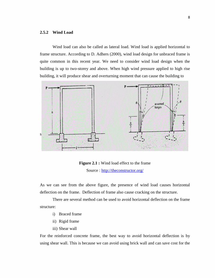
2.5.2 Wind Load
Wind load can also be called as lateral load. Wind load is applied horizontal to
frame structure. According to D. Adhers (2000), wind load design for unbraced frame is
quite common in this recent year. We need to consider wind load design when the
building is up to two-storey and above. When high wind pressure applied to high rise
building, it will produce shear and overturning moment that can cause the building to
sway or collapse.
Figure 2.1 : Wind load effect to the frame
Source : http://theconstructor.org/
As we can see from the above figure, the presence of wind load causes horizontal
deflection on the frame. Deflection of frame also cause cracking on the structure.
There are several method can be used to avoid horizontal deflection on the frame
structure:
i) Braced frame
ii) Rigid frame
iii) Shear wall
For the reinforced concrete frame, the best way to avoid horizontal deflection is by
using shear wall. This is because we can avoid using brick wall and can save cost for the
9
construction. Certain high rise building use combination of that three method and other
advance method to make sure the building is in good condition.
2.5.3 Earthquake
According to Widodo Pawirodikromo (2013), earthquake is a natural disaster
that happen due to release of energy in earth crust. This energy will produce seismic
wave. Earthquake will cause building to vibrate and cause wave motion. Usually the
earthquake will cause structure failure at the lower part. This thing happens because of
ground motion from the earthquake.
10
CHAPTER 3
METHODOLOGY
3.1 Introduction
This chapter will discuss about the method used to analyze the reinforced
concrete structure model. Finite element method (FEM) software is used to analyze the
unbraced frame model. We use ANSYS software to analyze the structure and to get
related information regarding the structure model. ANSYS is a software that used finite
element method for numerical solving for both linear and non-linear. In ANSYS, the
analysis is divided into three stages which are preprocessing, solution, and post
processing. In preprocessing part, the model is built using key point and lines after we
define the element type, materials and cross section of the structure. For solution stage,
we will specify the type of support, vertical load, and horizontal load for the structure. In
post processing stage, all the checking will be applied to the model.
In this study, four storey 3D reinforced concrete frame structure is model and
analyzed. Vertical load and horizontal load (wind load) is applied to the model. It is
important to consider wind load in our design to make sure the structure will not failed
when it exposed to wind storm.
11
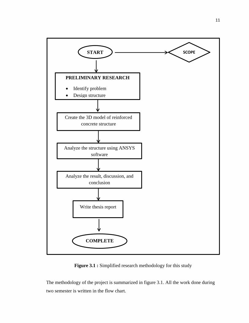
Figure 3.1 : Simplified research methodology for this study
The methodology of the project is summarized in figure 3.1. All the work done during
two semester is written in the flow chart.
START
PRELIMINARY RESEARCH
Identify problem
Design structure
Create the 3D model of reinforced
concrete structure
Analyze the structure using ANSYS
software
Analyze the result, discussion, and
conclusion
Write thesis report
COMPLETE
SCOPE