Finite Element Analysis for Edge-to-Edge Technique to ...
10
Acta of Bioengineering and Biomechanics Original paper Vol. 16, No. 4, 2014 DOI: 10.5277/ABB-00028-2014-02 Finite Element Analysis for Edge-to-Edge Technique to Treat Post-Mitral Valve Repair Systolic Anterior Motion QI ZHONG 1,2 , WENHUA ZENG 3 *, XIAOYANG HUANG 4 , XIAOJIA ZHAO 4 1 Applied Mathematics School, Xiamen University of Technology, Xiamen, People’s Republic of China. 2 Cognitive Science Department, Xiamen University, Xiamen, People’s Republic of China. 3 Software School, Xiamen University, Xiamen, People’s Republic of China. 4 Computer Science Department, Xiamen University, Xiamen, People’s Republic of China. Systolic anterior motion of the mitral valve is an uncommon complication of mitral valve repair, which requires immediate supple- mentary surgical action. Edge-to-edge suture is considered as an effective technique to treat post-mitral valve repair systolic anterior motion by clinical researchers. However, the fundamentals and quantitative analysis are vacant to validate the effectiveness of the addi- tional edge-to-edge surgery to repair systolic anterior motion. In the present work, finite element models were developed to simulate a specific clinical surgery for patients with posterior leaflet prolapse, so as to analyze the edge-to-edge technique quantificationally. The simulated surgery procedure concluded several actions such as quadrangular resection, mitral annuloplasty and edge-to-edge suture. And the simulated results were compared with echocardiography and measurement data of the patients under the mitral valve surgery, which shows good agreement. The leaflets model with additional edge-to-edge suture has a shorter mismatch length than that of the model merely under quadrangular resection and mitral annuloplasty actions at systole, which assures a better coaptation status. The stress on the leaflets after edge-to-edge suture is lessened as well. Key words: finite element modeling, mitral valve, edge-to-edge, systolic anterior motion 1. Introduction The mitral valve (MV), located between the left atrium (LA) and the left ventricle (LV), controls the blood flow from LA to LV. The mitral apparatus comprises four components: mitral annulus, two leaf- lets, i.e., anterior and posterior ones, chordae and two papillary muscles [7]. The chordae attach the leaflets to the two papillary muscles. Correct function of the mitral valve depends on the synergy of the four sub- structures and their proper mechanical behaviors. Mitral valve prolapse, a common valvular abnormal- ity, is defined as prolapse of one or both of the mitral leaflets into LA, which is mostly caused by tissue myxomatous degeneration [10]. Mitral valvuloplasty attempts to repair the prolapsed valve and resume the valvular function. Systolic anterior motion (SAM) of the mitral valve is an unusual mitral complication of MV repair, which is known as the anterior motion of the anterior leaflet toward the septum and it induces left ventricular outflow tract obstruction (LVOTO) and mitral regurgitation. A redundant anterior leaflet is frequently related to post-mitral repair SAM [9]. Jebara et al. [11] reported that the incidence of post-repair SAM and LVOTO is reduced by combin- ing posterior leaflet resection with a sliding plasty. However, Lee et al. [16] performing sliding plasty have had patients who had SAM developed. Triangu- lar resection of the anterior leaflet as advocated by Grossi et al. [9] significantly diminished the incidence of SAM from 9.1% to 3.4%. Besides, Roberto et al. [19] prospectively used edge-to-edge technique to repair SAM, and the early and 2-year results were ______________________________ * Corresponding author: Wenhua Zeng, School of Information Science and Engineering, Xiamen University, 361005 Xiamen. Tel: 08615969256926, e-mail: [email protected] Received: April 24th, 2014 Accepted for publication: May 8th, 2014
Transcript of Finite Element Analysis for Edge-to-Edge Technique to ...

Acta of Bioengineering and Biomechanics Original paperVol. 16, No. 4, 2014 DOI: 10.5277/ABB-00028-2014-02
Finite Element Analysis for Edge-to-Edge Techniqueto Treat Post-Mitral Valve Repair Systolic Anterior Motion
QI ZHONG1,2, WENHUA ZENG3*, XIAOYANG HUANG4, XIAOJIA ZHAO4
1 Applied Mathematics School, Xiamen University of Technology, Xiamen, People’s Republic of China.2 Cognitive Science Department, Xiamen University, Xiamen, People’s Republic of China.
3 Software School, Xiamen University, Xiamen, People’s Republic of China.4 Computer Science Department, Xiamen University, Xiamen, People’s Republic of China.
Systolic anterior motion of the mitral valve is an uncommon complication of mitral valve repair, which requires immediate supple-mentary surgical action. Edge-to-edge suture is considered as an effective technique to treat post-mitral valve repair systolic anteriormotion by clinical researchers. However, the fundamentals and quantitative analysis are vacant to validate the effectiveness of the addi-tional edge-to-edge surgery to repair systolic anterior motion. In the present work, finite element models were developed to simulatea specific clinical surgery for patients with posterior leaflet prolapse, so as to analyze the edge-to-edge technique quantificationally. Thesimulated surgery procedure concluded several actions such as quadrangular resection, mitral annuloplasty and edge-to-edge suture. Andthe simulated results were compared with echocardiography and measurement data of the patients under the mitral valve surgery, whichshows good agreement. The leaflets model with additional edge-to-edge suture has a shorter mismatch length than that of the modelmerely under quadrangular resection and mitral annuloplasty actions at systole, which assures a better coaptation status. The stress on theleaflets after edge-to-edge suture is lessened as well.
Key words: finite element modeling, mitral valve, edge-to-edge, systolic anterior motion
1. Introduction
The mitral valve (MV), located between the leftatrium (LA) and the left ventricle (LV), controls theblood flow from LA to LV. The mitral apparatuscomprises four components: mitral annulus, two leaf-lets, i.e., anterior and posterior ones, chordae and twopapillary muscles [7]. The chordae attach the leafletsto the two papillary muscles. Correct function of themitral valve depends on the synergy of the four sub-structures and their proper mechanical behaviors.Mitral valve prolapse, a common valvular abnormal-ity, is defined as prolapse of one or both of the mitralleaflets into LA, which is mostly caused by tissuemyxomatous degeneration [10]. Mitral valvuloplastyattempts to repair the prolapsed valve and resume the
valvular function. Systolic anterior motion (SAM) ofthe mitral valve is an unusual mitral complicationof MV repair, which is known as the anterior motionof the anterior leaflet toward the septum and it inducesleft ventricular outflow tract obstruction (LVOTO)and mitral regurgitation. A redundant anterior leafletis frequently related to post-mitral repair SAM [9].
Jebara et al. [11] reported that the incidence ofpost-repair SAM and LVOTO is reduced by combin-ing posterior leaflet resection with a sliding plasty.However, Lee et al. [16] performing sliding plastyhave had patients who had SAM developed. Triangu-lar resection of the anterior leaflet as advocated byGrossi et al. [9] significantly diminished the incidenceof SAM from 9.1% to 3.4%. Besides, Roberto et al.[19] prospectively used edge-to-edge technique torepair SAM, and the early and 2-year results were
______________________________
* Corresponding author: Wenhua Zeng, School of Information Science and Engineering, Xiamen University, 361005 Xiamen.Tel: 08615969256926, e-mail: [email protected]
Received: April 24th, 2014Accepted for publication: May 8th, 2014

QI ZHONG et al.4
satisfactory with total disappearance of SAM, of theLVOTO and of the mitral regurgitation.
Computational analysis of MV repair is a novelmethod to evaluate the effects of therapies on MVfunction. Finite element models not only reproducethe movement of the repaired valve, but also providefunctional information on the stress state of the valve,which is an important factor to a surgery but imagingtechniques cannot support. Kunzelman and colleagues[13] assessed mitral valve function after posteriorchordal replacement with expanded polytetrafluoro-ethylene suture using finite element methods. Andthey also built models to compare the coaptation andstresses between the valve with flexible ring annulo-plasty and the valve with rigid one [14]. Two com-mercial prostheses, the Physio ring and the Geoformring, were compared by Votta et al. [23] using finiteelement modeling. They also showed that finite ele-ment models could be used to determine ring sizeafter they simulated mitral annuloplasty on a patient-specific anatomy [21]. When it refers to edge-to-edgerepair modeling, several groups have made investiga-tion into this. Votta and colleagues [24] first simulatedthe edge-to-edge technology, and studied the impor-tance of the suture position, length and depth. Lau etal. [15]., Dal Pan et al. [18] and Andrea et al. [3], [4]also engaged in finite element modeling of edge-to-edge repair. Lau et al. [15] took the blood into consid-eration and built fluid-structure interaction model. Thefunctional and structural effects of percutaneous edge-to-edge double-orifice repair were studied as well, incomparison with traditional suture repair [4]. Re-cently, Tommaso et al. [17] developed patient-specificedge-to-edge models to apply finite element modelingto Mitral Clip intervention planning.
Among these present edge-to-edge repair finiteelement models, the material of the abnormal valvewas always neglected, and the normal valve materialmodels were used for the abnormal one. Nevertheless,the valve unable to coapt often suffers myxomatousdegeneration which enhances extensibility and de-creases stiffness of the valve leaflet and chordae [10].The specific material model is necessary for myx-omatous mitral valve. Otherwise, previous simulationswere regularly based on anticipated repair therapy inorder to obtain the optimal surgery plan. They wereseldom based on the clinical surgery and rarely com-pared the models with actual outcomes.
In the present work, we attempted to simulatea specific clinical surgery procedure conducted byRoberto et al. [19] mentioned above using finite ele-ment methods, and quantitatively evaluate the edge-to-edge technique to treat post-mitral valve repair
SAM. In our simulation, the geometry model of themitral valve is in accordance with the pathology de-scription of myxoid prolapsed mitral valve of thepatients in [19], and the special mechanical propertyof the myxomatous mitral valve tissue was consid-ered. The surgery actions such as quadrangular re-section, mitral annuloplasty and edge-to-edge suturewere simulated and their simulated results werecompared with patient echocardiographic and opera-tive data. The operation effect was evaluated by co-aptation length and stress distribution on the leafletmodel.
2. Materials and methods
In the clinical case of Roberto et al. [19], 4 pa-tients requiring mitral valve repair surgery sufferedchronic degenerative mitral regurgitation. Repairwas first achieved through a quadrangular resectionof the posterior leaflet and mitral annuloplasty witha ring. Routine perioperative transesophageal echo-cardiography showed SAM, sever LVOTO and mi-tral regurgitation. After resuming cardiopulmonarybypass, each patient had an additional edge-to-edgesuture.
We generated the geometry of the uncorrectedand corrected mitral valves by UGS NX software(Release 8.0). The structural dynamics of the mitralvalve was simulated by the explicit finite element codeLS-DYNA (Version: ls971d R5.0). Post-processing ofthe data was performed with LS-PREPOST.
2.1. Material model
The mitral valve of the patients in [19] suffersmyxomatous degeneration. The mechanical propertiesof the myxomatous mitral valve leaflet have beencharacterized by Barber et al. [5], who tested thestress and strain of the myxoid valve leaflet tissue inradial and circumferential directions. We have pre-sented an incompressible, hyperelastic constitutivemodel in [25] to characterize myxoid mitral leaflettissue mechanics. The model incorporates the trans-versely isotropic response and the layered structure ofthe tissue. The Cauchy stresses of the two-layeredcomposite in the first and second principal directions( 11σ ′ and 12σ ′ ) can be written as follows:when *
11 ff λλ < ,

Finite Element Analysis for Edge-to-Edge Technique to Treat Post-Mitral Valve Repair Systolic Anterior Motion 5
12
113
1212
221
21111 cos)1))1((exp(1 θλ
λλλσ −−+⎟⎟
⎠
⎞⎜⎜⎝
⎛−=′ fccrc ;
(1a)
when *11 ff λλ ≥ ,
;cos)(
cos)(1
222
52242
121
511412
221
21111
θλ
θλλλ
λσ
ccr
ccrc
f
f
++
++⎟⎟⎠
⎞⎜⎜⎝
⎛−=′
(1b)
when *22 ff λλ < ,
;sin)1))1((exp(
sin)1))1((exp(1
22
223
222
12
113
1212
221
21122
θλ
θλλλ
λσ
−−+
−−+⎟⎟⎠
⎞⎜⎜⎝
⎛−=′
f
f
ccr
ccrc
(2a)
when ,*22 ff λλ ≥
;sin)(
sin)(1
222
52242
121
511412
221
21122
θλ
θλλλ
λσ
ccr
ccrc
f
f
++
++⎟⎟⎠
⎞⎜⎜⎝
⎛−=′
(2b)
where *2
*1, ff λλ are the stretches at which the collagen
fibers in two layers are straightened. λ1, λ2, and λ3, arethe principal stretches. 2
515 and cc can be determined
from the condition that the exponential and linearregions are continuous at *
2*
1, ff λλ .
*1
14
*1
13
12
15 )1))1((exp( ff cccc λλ −−−= (3a)
*2
24
*2
23
22
25 )1))1((exp( ff cccc λλ −−−= (3b)
In equatons (1a) and (1b) and equations (2a) and(2b), λ1 and λ2 are the principal stretches; λf1 and λf2
are the stretches in the two fiber directions. ,12c ,1
3c14c and 1
5c are the material constants in the first layer,and ,2
2c ,23c ,2
4c and 25c are the material constants in
the second layer. These constants, determined bystress–strain data in [5] and listed in Table 1, wereused in our material model.
Likewise, the mechanical properties of the myxoidchordae differ from that of the normal one. Themodulus of the myxoid chordae is about 30 MPa whichis almost one fifth of the normal chordae modulus cal-culated in [6].
In surgery simulation, the materials of the flexi-ble ring of mitral annuloplasty and suture wireshould be taken into consideration as well. Thephysical property of the ring is characterized byYoung’s modulus E = 2.544 MPa and coefficient ofPoisson v = 0.45, as Kunzelman et al. described in[14]. Suture wire is made of polypropylene 4-0. Thematerial has been considered elastic linear withYoung’s modulus E = 3500 MPa and coefficient ofPoisson v = 0.38, based on [3].
2.2. Load and boundary condition
A time-dependent physiologic transvalvularpressure was applied on the surface of the leaflets[8] (shown in Fig. 1 and Fig. 2). It arises from thevarying atrioventricular pressure during cardiaccycle. When comparing Fig. 1 and Fig. 2, we foundthat the maximum pressure of the LV in the case ofmitral insufficiency is about 74 mm Hg which islower than that of the valve fully closed (120 mmHg), while the maximum pressure of LA in the mi-tral insufficiency case is higher. Herein, differenttime-dependent transvalvular pressures were ap-plied to fully closed valve model and insufficientlyclosed one in our simulation.
The motion of the mitral annulus in myxomatousvalve is not as significant as the normal valve, studiedby Kaplan and colleagues [12]. Therefore, the mitralannulus in the model can be regarded to be immobile.As the papillary muscles kept the distance from theannulus, they can be considered fixed in cardio cycleas well.
2.3. Surgery procedure simulation
The simulation of the surgery procedure conductedby Roberto et al. [19] can be divided into three parts.We first developed the myxomatous valve model andmimicked its dynamics including prolapse status.Secondly, original repair was simulated by altering the
Table 1. Myxomatous leaflet material constants in equations (1a) and (1b) and equations (2a) and(2b)
Constants c1 (MPa) 12c (MPa) 1
3c 14c (MPa) 2
2c (MPa) 23c 2
4c (MPa)
value 3.00e-5 6.84e-3 8.83 6.57 1.47e-2 6.65 3.76

QI ZHONG et al.6
myxomatous valve model to apply quadrangular re-section and mitral annuloplasty on it. Thirdly, basedon the original repaired valve model, edge-to-edgesuture was conducted as an additional repair. Thedynamics of the valve under the two repairs abovewere also calculated.
2.3.1. Myxomatous mitral valve model
Following the dysfunctional mitral valve infor-mation of the patients in [19], the myxomatous mitral
valve model was built. All patients had posteriorleaflet prolapse with chordal rupture and they hadlarge anterior leaflet with billowing. Thus, in ourmodel (shown as Fig. 3), the chordae linking to pos-terior leaflet was eliminated and the anterior leafletwas heightened. Jeffrey et al. [20] advanced the sizeof the mitral annulus in myxomatous valve, so thatwas significantly increased especially in the inter-peak span and we applied it in our model. Table 2lists the detailed dimensional parameters of themyxomatous mitral valve model. The leaflet model
(a) (b)
Fig. 1. The time-dependent pressure of LV (a) and LA (b) in the case of mitral valve fully closed
(a) (b)
Fig. 2. The time-dependent pressure of LV (a) and LA (b) in the case of mitral insufficiency
(a) (b) (c)
Fig. 3. 3D model of the mitral valve in a top view (a), a back view (b), and anisometric view (c)

Finite Element Analysis for Edge-to-Edge Technique to Treat Post-Mitral Valve Repair Systolic Anterior Motion 7
is a bit thicker than the anatomy description of thenormal leaflet attributed to the property of the myx-oid leaflet [10].
2.3.2. Original repair model
The original repair was achieved by a quadrangu-lar resection of the posterior leaflet and mitral annulo-plasty with a ring inserted.
The quadrangular resection procedure involvesremoving a section of the posterior leaflet from theannulus to the free margin, and drawing the sides ofthe resulting gap closer and suturing the leaflet to-gether[7]. The approach used for modeling this repairtechnique consisted first in cutting the nodes and ele-ments on the section at the center of the posteriorleaflet. And then the nodes on the cut line of the leaf-let were selected to have displacement applied tothem. Finally, these displacements drew the two linestogether, and they met in the center of the removed
section. Then, the suture lines joined the nodes overthe gap. Figure 4 illustrates the process.
The ring used in the surgery is a complete semi-rigid CE Physio ring (Edwards Life-sciences, Irvine,CA), with an anterior saddle shape and progressiveposterior flexibility [1]. The ratio between the inter-vallery span and the interpeak span is 4:3. Followingthese product descriptions, the artificial ring wasmodeled as a single profile line with certain ratio andshape. The ring model was discretized into 292 nodes.Mitral annuloplasty modeling was achieved via eachannulus node moving to the nearest node on the ring.
2.3.3. Edge-to-edge repair model
The edge-to-edge repair involves joining twoleaflets together and creating two small orifices. In thesurgery of Roberto et al. [19], it was conducted afterthe complications, namely SAM and LVOTO, of theoriginal repair appeared. All patients had a suture in
Table 2. Dimensional parameters of the myxomatous mitral valve model
Anterior leafletheight(mm)
Posterior leafletheight(mm)
Interpeakspan(mm)
Intervalleyspan(mm)
Leafletthickness
(mm)
Annuluslength(mm)
Value 30.3 13.8 35.0 32.0 2.0 106.4
(a) (b) (c)
Fig. 4. Quadrangular resection simulation: (a) section removed, (b) section closed, and (c) gap sutured
(a) (b) (c)
Fig. 5. Mitral annuloplasty simulation: (a) the image of the CE Physio ring;(b) the model before annuloplasty, the green line denoting the artificial ring; (c) the model after annuloplasty

QI ZHONG et al.8
the middle part of the free edge of the anterior andposterior leaflets. This short (5 mm) continuous suturetook big bites into the leaflets assuring coaptation andreducing the tissue redundancy. The stitch was placedat the limit of the rough zone to force coaptation inthis area, advocated by [2]. The suture procedure wassimulated by first connecting the nodes on each leafletover 5.4 mm on the border of the rough zone withspring beam element (k = 1000 g/mm). With the con-traction of the beam according to their internal con-stitutive law and tension, the leaflets progressivelyclose at the suture position.
3. Results
3.1. Closure dynamic
The present work simulated dynamics of mitralvalve in the myxomatous model, original repair modeland edge-to-edge repair model under transvalvularpressure during cardiac cycle.
Before surgery, the patient suffered serious mitralregurgitation (4 degree) and posterior leaflet pro-lapse. The myxomatous model simulated the pro-lapse process under the transvalvular pressure ofmitral insufficiency at early systolic pressure ramp
period when the anterior leaflet and posterior leafletclose to each other, as shown in Fig. 7. In normalcondition, the valve should fully close at systolicpeak, namely at t = 0.38 s here. However, the valvesuffering prolapse in this case cannot close sufficientlywith calculating regurgitation area of 8.9 cm2. Theposterior leaflet gradually closed to the annulusarea, and eventually went beyond the annulus withthe exceeding length of 5.4 mm, which was greaterthan the length threshold of the prolapse definition(2 mm) at systolic peak. The interpeak-span-velocityof the node on the edge of the posterior leaflet was150.1 mm/s, and its velocity in the directionperpendicular to the annulus was 273.0 mm/s at t =0.33 s.
After original repair, two leaflets contacted anddid not prolapse to the atrial side any more, but therewas a persistent aspect of redundancy of the anteriorleaflet with SAM and LVOTO observed by routinepost-repair transesophageal echocardiography and sig-nificant mitral regurgitation appeared after 2 to 10 min-utes after de-clamping the aorta. Then edge-to-edgerepair was done in clinic with the disappearance of theabove symptoms. The valve dynamics were calculatedunder original repair and following edge-to-edge re-pair in our models. Figure 8 shows the closure processof the valve model when the transvalvular pressuregradually went up to the maximum. The original sur-gery simulation shows regurgitation area being greatly
(a) (b) (c)
Fig. 6. Edge-to-edge repair simulation: (a) the model with suture joining the node on each leaflet;(b) and (c) are the two side views of the model when two leaflets close after beam contraction
Fig. 7. The simulation of the prolapse process before surgery at four successive time points

Finite Element Analysis for Edge-to-Edge Technique to Treat Post-Mitral Valve Repair Systolic Anterior Motion 9
eliminated at the beginning and the leaflet prolapsedisappeared.
The simulation of the edge-to-edge surgery dis-played the valve to be fully closed with regurgitationarea being zero at systolic peak (as shown in Fig. 9).
Figure 10 illustrates the valve closure status underthe maximum transvalvular pressure, the edge-to-edgesuture model shows the anterior leaflet edge cominginto apposition with its counterpart on the posterior
leaflet. However, the original repair model displaysthe posterior leaflet edge comes into the belly part ofthe anterior leaflet, namely, the anterior leaflet hasmuch redundancy, which is consistent with the clini-cal surgery observation and the redundancy anteriorleaflet is considered to be the reason of SAM andLVOTO.
In order to compare the coaptation quality of thevalve models, the quantitative evaluation criterion of
Fig. 8. The simulation of the coaptation process after the original repair at four successive time points
Fig. 9. The simulation of the coaptation process after the secondary repair at four successive time points
(a) (b)
(c) (d)
Fig. 10. Valve closure status under the maximum transvalvular pressure:(a) and (c) are the side views of the valve model under original surgery and the one under edge-to-edge suture, respectively;
(b) and (d) are their leaflet half models. Black curve outlines the middle line of the leaflets

QI ZHONG et al.10
coaptation defined by Votta et al. [23] was introduced.As shown in Fig. 11, L measure is assumed to be thelength of the line from the beginning of the coaptingtract to the leaflet free margin, which is divided intotwo terms: the length of the tract where leaflets areactually in contact (Lcoapt) and the mismatch betweenthe free margins of the two coapting leaflets (Lfm). Thegood coaptation model was defined as the one withlong Lcoapt and short Lfm.
Table 3 lists the coaptation measurement of thetwo valve models. The valve model after original re-pair have longer Lcoapt, but its Lfm is much longer thanthat of the edge-to-edge-repair model (0.73 mm).
Fig. 11. Definition of the measured quantitiesof leaflets’ coaptation in half model.
Blue areas denote the rough zone of two leaflets.L measurement is equal to the sum of Lcoapt and Lfm
Table 3. The coaptation measurement comparisonbetween the original repair model and the edge-to-edge one
Original repairmodel (mm)
Edge-to-edge repairmodel (mm)
Lcoapt 4.58 2.27Lfm 10.89 0.73
3.2. Leaflet stress
The leaflets in the model bore time-dependenttransvalvular pressure during cardio cycle. The vonMises stresses calculated for the two leaflets wereincreasing with the pressure rise. As different time-dependent transvalvular pressures were applied tofully closed valve model and insufficiently closed one,we compared the von Mises stress distributions of thedifferent valve models when they were under the sametransvalvular pressure (7.92 kPa). The leaflets stressdistributions of the models are illustrated in Fig. 12.
In the three models, the maximum stress is con-formably observed near the annulus region; the belliesof the leaflets also experience high stress. The poste-rior leaflets carry fewer loads than the anterior leafletin the myxomatous valve model and the edge-to-edgerepair model. In the edge-to-edge repair model, thecommissural areas also appear under high stress con-centration. The maximum stress in the original repairvalve model is up to 489.5 kPa, which is higher thanthat of the myxomatous valve model (377.3 kPa) andthat of the edge-to-edge repair model (203.1 kPa).
4. Discussion
Through simulating a clinical surgery procedure,we obtained the quantitative information of the valvesdynamics and stress distribution both before and afterrepairs. Our simulation demonstrated that the originalrepair including quadrangular resection and mitralannuloplasty prevented the leaflet from prolapsingtoward the atrial side. The reason is that the originalcorrect simulation has shorten the interpeak span ofthe valve, which enabled the anterior leaflet and theposterior one to meet each other and avoid the leaflet
(a) (b) (c)
Fig. 12. Leaflets’ von Mises stress distributions for the myxomatous valve model (a),the original repair model (b) and the edge-to-edge model (c)
Finite Element Analysis for Edge-to-Edge Technique to Treat Post-Mitral Valve Repair Systolic Anterior Motion 11
prolapsing. However, the original correct simulationalso shows that this repair could not make the valveclose fully and perfectly with regurgitation area andlong mismatch length (10.89 mm) owing to the re-dundant anterior leaflet. When the blood flowed to-ward LVOT, the redundant anterior leaflet wouldmove to the septum reinforced by the Venturi effectand consequently lose the coaptation point inducingmitral regurgitation and LVOTO during systolic pe-riod [19]. The edge-to-edge technology sutured thetwo leaflets together, which restricted the anteriormovement and made good coaptation with short mis-match length (0.73 mm), so as to successively elimi-nate existing mitral regurgitation, SAM and LVOTO.Furthermore, the comparison of the magnitudes of thevon Mises stress calculated in the two repair modelsindicated that the edge-to-edge technology also re-duced the loads carried by leaflet surface, whichmight guarantee the persistent validation of the edge-to-edge surgery.
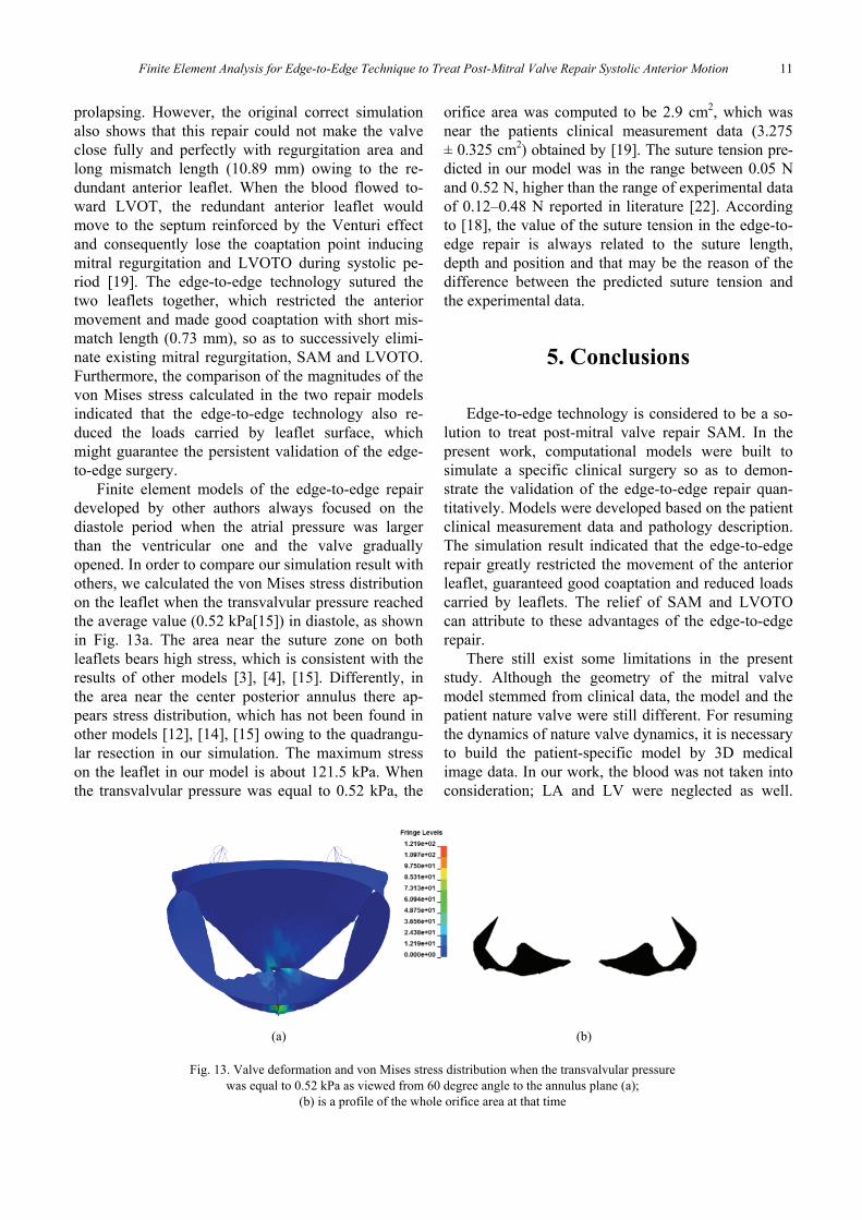
Finite element models of the edge-to-edge repairdeveloped by other authors always focused on thediastole period when the atrial pressure was largerthan the ventricular one and the valve graduallyopened. In order to compare our simulation result withothers, we calculated the von Mises stress distributionon the leaflet when the transvalvular pressure reachedthe average value (0.52 kPa[15]) in diastole, as shownin Fig. 13a. The area near the suture zone on bothleaflets bears high stress, which is consistent with theresults of other models [3], [4], [15]. Differently, inthe area near the center posterior annulus there ap-pears stress distribution, which has not been found inother models [12], [14], [15] owing to the quadrangu-lar resection in our simulation. The maximum stresson the leaflet in our model is about 121.5 kPa. Whenthe transvalvular pressure was equal to 0.52 kPa, the
orifice area was computed to be 2.9 cm2, which wasnear the patients clinical measurement data (3.275± 0.325 cm2) obtained by [19]. The suture tension pre-dicted in our model was in the range between 0.05 Nand 0.52 N, higher than the range of experimental dataof 0.12–0.48 N reported in literature [22]. Accordingto [18], the value of the suture tension in the edge-to-edge repair is always related to the suture length,depth and position and that may be the reason of thedifference between the predicted suture tension andthe experimental data.
5. Conclusions
Edge-to-edge technology is considered to be a so-lution to treat post-mitral valve repair SAM. In thepresent work, computational models were built tosimulate a specific clinical surgery so as to demon-strate the validation of the edge-to-edge repair quan-titatively. Models were developed based on the patientclinical measurement data and pathology description.The simulation result indicated that the edge-to-edgerepair greatly restricted the movement of the anteriorleaflet, guaranteed good coaptation and reduced loadscarried by leaflets. The relief of SAM and LVOTOcan attribute to these advantages of the edge-to-edgerepair.
There still exist some limitations in the presentstudy. Although the geometry of the mitral valvemodel stemmed from clinical data, the model and thepatient nature valve were still different. For resumingthe dynamics of nature valve dynamics, it is necessaryto build the patient-specific model by 3D medicalimage data. In our work, the blood was not taken intoconsideration; LA and LV were neglected as well.
(a) (b)
Fig. 13. Valve deformation and von Mises stress distribution when the transvalvular pressurewas equal to 0.52 kPa as viewed from 60 degree angle to the annulus plane (a);
(b) is a profile of the whole orifice area at that time

QI ZHONG et al.12
These two simplifications limited the simulation ofthe anterior leaflet movement toward the septum un-der the blood flow which induced post-mitral valverepair SAM and LVOTO.
Model personalization is a big challenge for mitralvalve repair simulation using finite element method,but this in-vitro and noninvasive method is very at-tractive for researchers to study the effects of thera-pies on mitral valve function. Finite element modelingmay become a useful tool for mitral valve repair plan-ning in the near future.
Acknowledgements
We gratefully acknowledge support from the National Natu-ral Science Foundation of China (No. 61102137, 61271336,61327001).
References
[1] Carpentier-Edwards Physio Annuloplasty Ring. Available:http://www.edwards.com/prod; ucts/rings/pages/physio.aspx
[2] ALFIERI O., MAISANO F., BONIS M.D. et al., The double-orificetechnique in mitral valve repair: a simple solution for complexproblems, J. Thorac. Cardiov. Sur., 2001, 122, 674–681.
[3] AVANZINI A., A Computational Procedure for Prediction ofStructure Effects of Edge-to-Edge Repair on Mitral Valve,J. Biomech. Eng., 2008, 130, 031015-1-031015-10.
[4] AVANZINI A., DONZELLA G., LIBRETTI L., Functional andstructural effects of percutaneous edge-to-edge double-orificerepair under cardiac cycle in comparison with suture repair,P. I. Mech. Eng. H, 2011, 225, 959–971.
[5] BARBER J.E., KASPER F.K., RATLIFF N.B. et al., Mechanicalproperties of myxomatous mitral valves, J. Thorac. Cardiov.Sur., 2001, 122.
[6] BARBER J.E., RATLIFF N.B., COSGROVE D.M. et al., Myxo-matous mitral valve chordae. I: Mechanical properties,J. Heart Valve Dis, 2001, 10, 320–324.
[7] DOMINIK J., ZACEK P., Heart Valve Surgery: An IllustratedGuide, Springer, 2010.
[8] FENG M., Research on Electronic Modeling and Simulationof Mitral Insufficiency, Xiamen University, 2013.
[9] GROSSI E.A., STEINBERG B.M., LEBOUTILLIER M.R. et al.,Decreasing incidence of systolic anterior motion after mitralvalve reconstruction, Circulation, 1994, 90, II195–197.
[10] Hayek E., Gring C.N., Griffin B.P., Mitral Valve Prolapse,The Lancet, 2005, 365, 507–518.
[11] JEBARA V.A., MIHAILEANU S., ACAR C. et al., Left ventricularoutflow tract obstruction after mitral valve repair. Results of thesliding leaflet technique, Circulation, 1993, 88, II30–34.
[12] KAPLAN S.R., BASHEIN G., SHEEHAN F.H. et al., Three-dimensional echocardiographic assessment of annular shapechanges in the normal and regurgitant mitral valve, Am.Heart J., 1999, 139, 378–387.
[13] KUNZELMAN K., REIMINK M.S., VERRIER E.D. et al., Re-placement of mitral valve posterior chordae tendineae withexpanded polytetrafluoroethylene suture: a finite elementstudy, J. Cardiac. Surg., 1996, 11, 136–145.
[14] KUNZELMAN K.S., REIMINK M.S., R.P. C., Flexible versusrigid ring annuloplasty for mitral valve annular dilation: a fi-nite element model, J. Heart Valve Dis, 1998, 7, 108–116.
[15] LAU K., DÍAZ-ZUCCARINI V., SCAMBLER P. et al., Fluid-structure interaction study of the edge-to-edge repair tech-nique on the mitral valve, J. Biomech., 2011, 2409–2417.
[16] LEE K.S., STEWART W.J., SAVAGE R.M. et al., Systolic anteriormotion of mitral valve after the posterior leaflet sliding advance-ment procedure, Ann. Thorac. Surg., 1994, 57, 1338–1340.
[17] MANSI T., VOIGT I., GEORGESCU B. et al., An integrated frame-work for finite-element modeling of mitral valve biomechanicsfrom medical images: Application to MitralClip interventionplanning, Med. Image Anal., 2012, 16, 1330–1346.
[18] PAN F.D., DONZELLA G., FUCCI C. et al., Structural effects ofan innovative surgical technique to repair heart valve de-fects, J. Biomech., 2005, 38, 2460–2471.
[19] ROBERTO M., AL A.N., MAURO L. et al., Edge-to-Edge Tech-nique to Treat Post-Mitral Valve Repair Systolic AnteriorMotion and Left Ventricular Outflow Tract Obstruction, Ann.Thorac. Surg., 2005, 76, 471–474.
[20] SILBIGER J.J., Anatomy, mechanics, and pathophysiologyof the mitral annulus, Am. Heart J., 2012, 164, 163–176.
[21] STEVANELLA M., MAFFESSANTI F., CONTI C.A. et al., MitralValve Patient-Specific Finite Element Modeling from Car-diac MR: Application to an Annuloplasty Procedure, Cardio-vasc. Engineering Technol., 2011, 2, 66–76.
[22] TIMEK T.A., NIELSEN S.L., LAI D.T. et al., Mitral annularsize predicts Alfieri stitch tension in mitral edge-to-edge re-pair, J. Heart Valve Dis., 2004, 13, 165–173.
[23] VOTTA E., MAISANO F., BOLLING S.F. et al., The GeoformDisease-Specific Annuloplasty System: A Finite ElementStudy, Ann. Thorac. Surg., 2007, 84, 92–101.
[24] VOTTA E., MAISANO F., SONCINI M. et al., 3-D computationalanalysis of the stress distribution on the leaflets after edge-to-edge repair of mitral regurgitation, J. Heart Valve Dis.,2002, 11, 810–822.
[25] ZHONG Q., ZENG W., HUANG X. et al., Constitutive modelingand finite element analysis of myxomatous mitral leaflet tis-sue, J. Mech. Med. Biol., 2014, 14.