A Finite Element Investigation of Elastic Flow Asymmetries ...
Finite Deformations and Internal Forces in Elastic-Plastic
Crystals: Interpretations From Nonlinear Elasticity and Anharmonic Lattice Statics
by J. D. Clayton and D. J. Bammann
ARL-RP-274 September 2009
A reprint from Journal of Engineering Materials and Technology, Vol. 131, pp. 041201-1–041201-15, October 2009.
Approved for public release; distribution is unlimited.
NOTICES
Disclaimers The findings in this report are not to be construed as an official Department of the Army position unless so designated by other authorized documents. Citation of manufacturer’s or trade names does not constitute an official endorsement or approval of the use thereof. Destroy this report when it is no longer needed. Do not return it to the originator.
Army Research Laboratory Aberdeen Proving Ground, MD 21005-5066
ARL-RP-274 September 2009
Finite Deformations and Internal Forces in Elastic-Plastic Crystals: Interpretations From Nonlinear Elasticity
and Anharmonic Lattice Statics
J. D. Clayton
Weapons and Materials Research Directorate, ARL
D. J Bammann Mississippi State University
A reprint from Journal of Engineering Materials and Technology, Vol. 131, pp. 041201-1–041201-15, October 2009.
Approved for public release; distribution is unlimited.
REPORT DOCUMENTATION PAGE Form Approved OMB No. 0704-0188
Public reporting burden for this collection of information is estimated to average 1 hour per response, including the time for reviewing instructions, searching existing data sources, gathering and maintaining the data needed, and completing and reviewing the collection information. Send comments regarding this burden estimate or any other aspect of this collection of information, including suggestions for reducing the burden, to Department of Defense, Washington Headquarters Services, Directorate for Information Operations and Reports (0704-0188), 1215 Jefferson Davis Highway, Suite 1204, Arlington, VA 22202-4302. Respondents should be aware that notwithstanding any other provision of law, no person shall be subject to any penalty for failing to comply with a collection of information if it does not display a currently valid OMB control number. PLEASE DO NOT RETURN YOUR FORM TO THE ABOVE ADDRESS.
1. REPORT DATE (DD-MM-YYYY)
September 2009 2. REPORT TYPE
Reprint 3. DATES COVERED (From - To)
October 2009 4. TITLE AND SUBTITLE
Finite Deformations and Internal Forces in Elastic-Plastic Crystals: Interpretations From Nonlinear Elasticity and Anharmonic Lattice Statics
5a. CONTRACT NUMBER
5b. GRANT NUMBER
5c. PROGRAM ELEMENT NUMBER
6. AUTHOR(S)
J. D. Clayton and D. J. Bammann* 5d. PROJECT NUMBER
5e. TASK NUMBER
5f. WORK UNIT NUMBER
7. PERFORMING ORGANIZATION NAME(S) AND ADDRESS(ES)
U.S. Army Research Laboratory ATTN: RDRL-WMT-D Aberdeen Proving Ground, MD 21005-5066
8. PERFORMING ORGANIZATION REPORT NUMBER
ARL-RP-274
9. SPONSORING/MONITORING AGENCY NAME(S) AND ADDRESS(ES)
10. SPONSOR/MONITOR'S ACRONYM(S)
11. SPONSOR/MONITOR'S REPORT NUMBER(S)
12. DISTRIBUTION/AVAILABILITY STATEMENT
Approved for public release; distribution is unlimited.
13. SUPPLEMENTARY NOTES
A reprint from Journal of Engineering Materials and Technology, Vol. 131, pp. 041201-1–041201-15, October 2009. *Center for Advanced Vehicular Systems, Mississippi State University, Starkville, MS 39762
14. ABSTRACT
Large deformation kinematics and internal forces arising from defects in crystalline solids are addressed by a nonlinear kinematic description and multiscale averaging concepts. An element of crystalline material with spatially uniform properties and containing defects such as dislocation lines and loops is considered. The average deformation gradient for this element is decomposed multiplicatively into terms accounting for effects of dislocation flux, recoverable elastic stretch and rotation, and residual elastic deformation associated with self-equilibrating internal forces induced by defects. Two methods are considered for quantifying average residual elastic deformation: continuum elasticity and discrete lattice statics. Average residual elastic strains and corresponding average residual elastic volume changes are negligible in the context of linear elasticity or harmonic force potentials but are not necessarily inconsequential in the more general case of nonlinear elasticity or anharmonic interactions.
15. SUBJECT TERMS
elasticity, plasticity, dislocations, lattice statics, molecular dynamics, multiscale modeling, nonlinear elasticity
16. SECURITY CLASSIFICATION OF: 17. LIMITATION OF ABSTRACT
UU
18. NUMBER OF PAGES
22
19a. NAME OF RESPONSIBLE PERSON
John D. Clayton a. REPORT
Unclassified b. ABSTRACT
Unclassified c. THIS PAGE
Unclassified 19b. TELEPHONE NUMBER (Include area code)
410-278-6146 Standard Form 298 (Rev. 8/98) Prescribed by ANSI Std. Z39.18
1
t�tTci�pbsatvtebsrmtlsfiv
dnp
EfiE
J
Downlo
J. D. ClaytonMem. ASME
Impact Physics,US Army Research Laboratory,
Aberdeen Proving Ground, MD 21005e-mail: [email protected]
D. J. BammannFellow ASME
Center for Advanced Vehicular Systems,Mississippi State University,
Starkville, MS 39762e-mail: [email protected]
Finite Deformations and InternalForces in Elastic-Plastic Crystals:Interpretations From NonlinearElasticity and Anharmonic LatticeStaticsLarge deformation kinematics and internal forces arising from defects in crystallinesolids are addressed by a nonlinear kinematic description and multiscale averagingconcepts. An element of crystalline material with spatially uniform properties and con-taining defects such as dislocation lines and loops is considered. The average deforma-tion gradient for this element is decomposed multiplicatively into terms accounting foreffects of dislocation flux, recoverable elastic stretch and rotation, and residual elasticdeformation associated with self-equilibrating internal forces induced by defects. Twomethods are considered for quantifying average residual elastic deformation: continuumelasticity and discrete lattice statics. Average residual elastic strains and correspondingaverage residual elastic volume changes are negligible in the context of linear elasticityor harmonic force potentials but are not necessarily inconsequential in the more generalcase of nonlinear elasticity or anharmonic interactions. �DOI: 10.1115/1.3183773�
Keywords: nonlinear elasticity, plasticity, lattice statics, dislocations, multiscalemodeling
IntroductionBy typical definition, plastic deformation in crystalline solids
akes place by the motion or flux of distributions of dislocations1,2�. An element of material through which a net flux of disloca-ions has passed exhibits a permanent �plastic� shape change �3�.he dislocation lines within the element, i.e., displacement dis-ontinuities across the slip plane in the context of Volterra defectsn elastic continua, may also contribute to this plastic deformation4–7�. However, plastic deformation in this context does not ex-licitly account for the additional change in dimensions of theody due to residual elastic deformation associated with localtress fields �i.e., eigenstresses �7�� induced by defects. For ex-mple, dislocation glide preserves the volume of the crystal, andangential displacement �i.e., slip� discontinuities do not alter theolume occupied by the material. Yet ample evidence suggestshat dislocation lines affect the volume of crystals �8–11�. Storednergies associated with elastic fields of defects are importantecause they affect recrystallization �9,12� and the fraction oftress power converted to temperature rise at high deformationates �13� that can lead to strain softening and shear localization inetals during dynamic failure events. Large numbers of disloca-
ions, twins, and stacking faults can be generated during shockoading �14�, and presumably the corresponding volume changes,hape changes, and stored energies associated with local stresselds of these defects affect the observed response �e.g., pressure-olume or stress-strain profiles� under such conditions �15�.Defects of interest in the present work are those that can be
escribed in a continuum sense by closed displacement disconti-uities tangential to an internal surface �i.e., crystallographiclane� in a volume element of material. These include gliding
Contributed by the Materials Division of ASME for publication in the JOURNAL OF
NGINEERING MATERIALS AND TECHNOLOGY. Manuscript received January 14, 2009;nal manuscript received March 30, 2009; published online August 27, 2009. Assoc.
ditor: Hussein Zbib.ournal of Engineering Materials and TechnologyCopyright © 20
aded 27 Aug 2009 to 128.63.66.91. Redistribution subject to ASME
straight or curved dislocations lines, dislocation loops, as well aspartial dislocations. Motion of dislocation defects through a re-gion of the crystal results in plastic shape change as mentionedabove but preserves the lattice spacing �3�; this requires coopera-tive motion of leading and trailing partials for the case of partialdislocations. Residual elastic stress fields from disclination linesand loops are also considered �6,16,17�, though their contributionto the plastic shape change �18� is not addressed explicitly. Alsonot considered are voids, fractures, and point defects �19,20� thatmay have finite volume and affect the lattice differently. Disloca-tion climb is also not considered here, because it generally in-volves vacancy migration �21�.
Modeling efforts directed toward large deformation kinematicsof crystalline solids feature a long history. In the absence of de-fects, thermal or electromagnetic effects, or internal relative dis-placements among atoms of different sublattices, a deformationgradient F applied uniformly over an element of mechanicallystressed material and the linear mapping FE of its interatomicbond vectors �i.e., primitive Bravais lattice vectors and basis vec-tors at each lattice point� coincide. This is typically called theCauchy–Born hypothesis �22,23� and is written as F=FE. Whenplastic deformation takes place, the description is typically ex-tended to F=FEFP �3,24,25�, where FP accounts for the presenceand motion of dislocations or other defects. The idea of a relaxedintermediate or natural configuration implicit in this multiplicativedecomposition was introduced somewhat earlier �26�. Early stud-ies of continuously distributed lattice defects considered self-stresses and residual elastic deformations resulting from defects�27–29�. In such instances the plastic deformation FP inducingdiscontinuities in the first place was often not considered explic-itly, nor was elastic deformation FE associated with external load-ing, since the element of material containing defects was in a state
of self-stress. Defect content associated with heterogeneous elasticOCTOBER 2009, Vol. 131 / 041201-109 by ASME
license or copyright; see http://www.asme.org/terms/Terms_Use.cfm
acd
slcgEtttd�dfiafi
alanelrnuctpcga
afinasc�etttgtmlb
FtcefaoedeTtcnt
0
Downlo
nd inelastic deformations �i.e., tangent mappings in the multipli-ative decomposition� can be described using tensor calculus andifferential geometry �3,16,24,30–37�.In this work a three-term decomposition, F=FEFIFP, is as-
igned to describe the kinematics of a volume element of crystal-ine material containing lattice defects. For simplicity, isothermalonditions are assumed �e.g., no thermal expansion�. Elastic tan-ent map FE used here is analogous to that of Born, Huang, andricksen �22,23,38�. Plastic tangent map FP results from cumula-
ive effects of fluxes of dislocations �1,2,39� and slip discontinui-ies associated with defects within the element �4,5�. Intermediateerm FI �or its stretch or rotational components� has been intro-uced in a number of works with various definitions16,34–36,40–42�. Here FI represents the average residual elasticeformation of the element induced by local stress and strainelds of defects contained within, and corresponds to the volumeverage of residual elastic deformation in the context of defecteld theories �27–29�.In Sec. 3, the externally unloaded volume element is treated as
n elastic body with homogeneous elastic constants, in static equi-ibrium, and containing internal displacement discontinuitiescross which traction is continuous. The element is free of exter-al traction but may support residual stresses. The self-quilibrium conditions result in an integral equation for FI. Forinear-elastic constitutive behavior, FI reduces to the unit tensor inectangular Cartesian coordinates, but FI does not so reduce foronlinear behavior. Following previous studies �29,43,44�, vol-me changes resulting from the stored energy of defect lines areonsidered for cubic and isotropic crystals. A proportionality rela-ionship between the line density of dislocations or disclinationser unit reference volume of the solid and this residual volumehange is obtained. Analytical elasticity solutions for defect ener-ies are considered along with experimental data �45� to confirmccuracy of the theory.
In Sec. 4, the externally unloaded volume element is identifieds a set of discrete atoms in static equilibrium and free of externalorces. According to this description, all interatomic forces vanishn a perfect lattice free of defects �e.g., no bond stretching�, butonzero forces may exist among atoms when they are arranged inn imperfect way �i.e., when defects are present�. In this case, theelf-equilibrium conditions are equivalent to vanishing of staticomponents of the average virial stress for the set of atoms38,46�. The potential energy is expanded about a perfect refer-nce state, leading to expressions for stress and elastic stiffnessensors in terms of harmonic and anharmonic parts of the poten-ial. When atomic interactions are harmonic, equilibrium demandshat FI as defined here should reduce to the unit tensor, analo-ously to the linear-elastic continuum interpretation. However, inhe more general scenario of anharmonic interactions �47–49� thatay be physically significant in the vicinity of defect cores where
arge atomic displacements arise, the derivations suggest FI coulde non-negligible.A number of theoretical models have introduced a term akin to
I to represent elastic fields of crystal defects �16,34,35,41�,hough previous works did not always include precise mathemati-al definitions for FI or quantitative estimates of its magnitude inngineering materials. The present work gives exact definitionsor FI using anisotropic nonlinear continuum elasticity �Sec. 3�nd discrete lattice statics �Sec. 4�. Also, the present work dem-nstrates how residual elastic volume changes ��det FI� can bestimated for defect lines, extending earlier analysis �43� to ad-ress geometric nonlinearity. Previous authors �8,10,43� did notmphasize possible shape changes associated with FI �thoughoupin and Rivlin �44� mentioned shape changes briefly� nor didhey attempt to place their derivations in the context of multipli-ative elastoplasticity as demonstrated in the present work. Theew atomic-scale definition of FI in Sec. 4 may prove useful in
he context of multiscale computations of nonlinear elastic and41201-2 / Vol. 131, OCTOBER 2009
aded 27 Aug 2009 to 128.63.66.91. Redistribution subject to ASME
plastic properties of crystals �50,51� and offers a more accuratetreatment of defect cores than classical continuum elasticity.
The following notation is used. Scalars and individual compo-nents of vectors and tensors are written in italics, while vectorsand tensors are written in bold. Einstein’s summation conventionapplies for repeated indices. The • symbol denotes the scalar prod-uct of vectors �a •b=aaba=a1b1+a2b2+a3b3�, while � indicatesthe outer product ��a � b�ab=aabb�. Juxtaposition of second-ranktensors implies summation over one set of adjacent indices��AB�.c
a =AabBbc�. Indices in parentheses are symmetric �2A�ab�=Aab+Aba�. Superposed �1 denotes inversion. Subscripted com-mas denote partial differentiation.
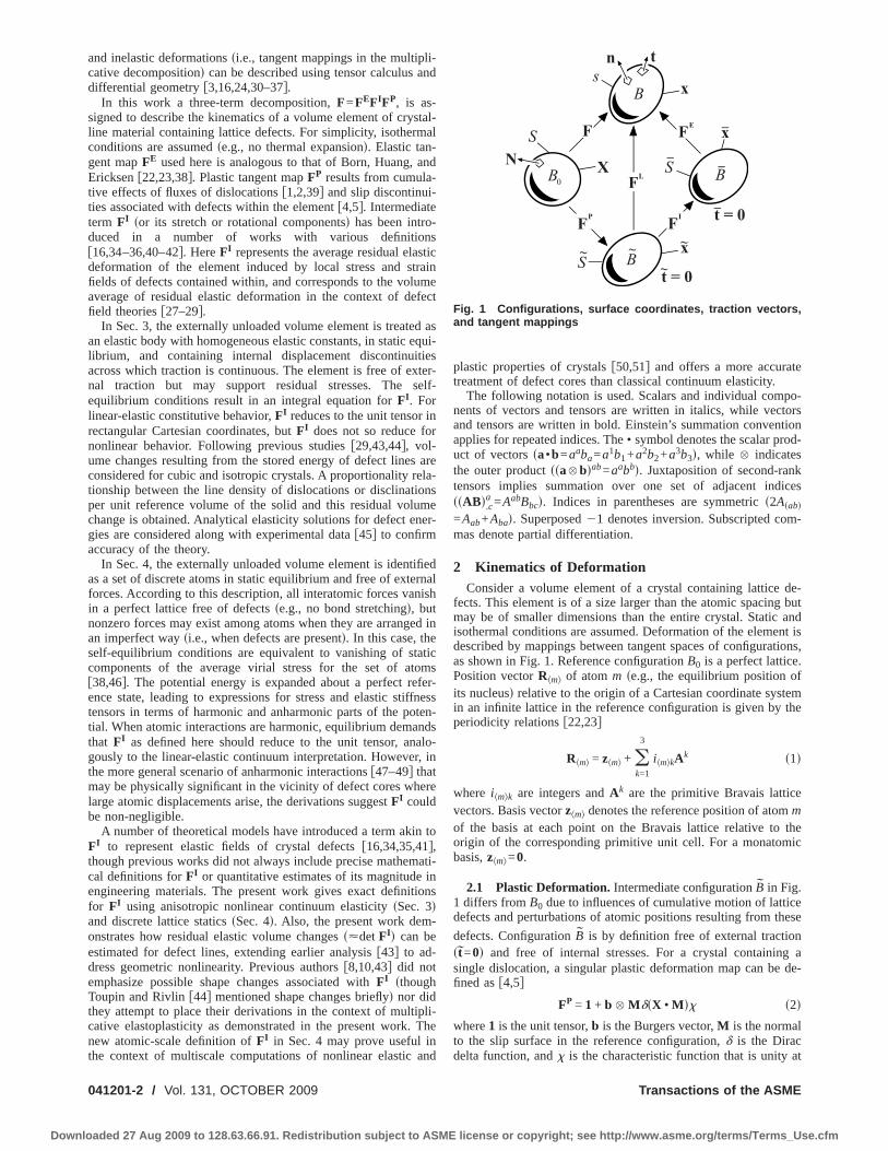
2 Kinematics of DeformationConsider a volume element of a crystal containing lattice de-
fects. This element is of a size larger than the atomic spacing butmay be of smaller dimensions than the entire crystal. Static andisothermal conditions are assumed. Deformation of the element isdescribed by mappings between tangent spaces of configurations,as shown in Fig. 1. Reference configuration B0 is a perfect lattice.Position vector R�m� of atom m �e.g., the equilibrium position ofits nucleus� relative to the origin of a Cartesian coordinate systemin an infinite lattice in the reference configuration is given by theperiodicity relations �22,23�
R�m� = z�m� + �k=1
3
i�m�kAk �1�
where i�m�k are integers and Ak are the primitive Bravais latticevectors. Basis vector z�m� denotes the reference position of atom mof the basis at each point on the Bravais lattice relative to theorigin of the corresponding primitive unit cell. For a monatomicbasis, z�m�=0.
2.1 Plastic Deformation. Intermediate configuration B in Fig.1 differs from B0 due to influences of cumulative motion of latticedefects and perturbations of atomic positions resulting from these
defects. Configuration B is by definition free of external traction�t=0� and free of internal stresses. For a crystal containing asingle dislocation, a singular plastic deformation map can be de-fined as �4,5�
FP = 1 + b � M��X • M�� �2�
where 1 is the unit tensor, b is the Burgers vector, M is the normalto the slip surface in the reference configuration, � is the Dirac
B
BS
x
x
x
X
t
t = 0
t = 0~
FEF
FP
F_
_
_S
N
s
~F
B0 L
I
B~
_
S~
n
Fig. 1 Configurations, surface coordinates, traction vectors,and tangent mappings
delta function, and � is the characteristic function that is unity at
Transactions of the ASME
license or copyright; see http://www.asme.org/terms/Terms_Use.cfm
rTt�
we
wciwAed
wbattist�
mE
wdEot
vo
Am
wtl�f
d
J
Downlo
eference coordinates X on slipped surface � and zero elsewhere.he Cartesian coordinate system for X is chosen with its origin in
he slip plane. A dislocation density tensor corresponding to Eq.2� is �4�
� = b � �0��L� �3�
here �0 is the unit tangent to the dislocation line L in the refer-nce configuration. From Eqs. �2� and �3�,
b = −X+
X−
FPdX =A
�NdA �4�
here the line integral in the first of Eq. �4� takes place acrossoordinates above �X+� and below �X−� the slipped surface, andntegration in the second of Eq. �4� proceeds over oriented area Aith unit normal N such that �0•N=1 at the intersection of L and. If defects are introduced sequentially, a logical nonsingularxtension of Eq. �2� for a volume element containing multipleislocation lines is
FP = m=1
n �1 + V−1 b � M����dV� = m=1
n
�1 + V−1b � M��
�5�
here the product is taken over n dislocations, each with a possi-ly different Burgers vector b and constant normal vector M to anssumed flat slipped surface of reference area �. The volume ofhe element in the reference configuration is denoted by V. Notehat Eq. �5� depends on the order in which each dislocation isntroduced. Since b�M, Eq. �5� consists of a product of simplehears and volume is conserved, i.e., JP=det FP=1. For a collec-ion of j straight stationary dislocation line populations of densityi= lim
V→0
�Li /V�, Burgers vector bi, unit tangent �0i , and plane nor-
al Mi, the dislocation density in Eq. �3� and Burgers integral inq. �4� can be extended as
� = V−1L
b � �0dL = �i=1
j
�ibi� �0
i �6�
B =A
�NdA =A�i=1
j
�ibi��0i • NdA� �7�
ith B the summed projection of all local Burgers vectors b ofislocation lines passing through area A. The line integration inq. �6� proceeds over all dislocations of total length L. The secondf Eq. �6� pertains to j dislocation populations with the sameangent line and local Burgers vector for each value of i.
A more general definition of average plastic deformation of aolume element accounts for the history of generation and motionf defects within it, in which case FP is defined as the solution of
FP = LPFP, FP t=0 = 1 �8�
verage plastic velocity gradient LP is dictated by the flux � ofobile dislocations �2,17,39,52�:
L.�P� = �������, ���� = V−1
L
bi�i�vi�dL = �i=1
j
�ibi�i�vi�
�9�
here � is the permutation tensor, and �i and vi are, respectively,he uniform tangent line and velocity of every dislocation in popu-ation i. All vector and tensor indices written in Greek font in Eq.9� are subject to the Einstein summation convention and are re-
erred to configuration B. Since dislocation segments have perpen-˙P P P P
icular velocities and tangent lines, J =J tr L =0 and J =1.ournal of Engineering Materials and Technology
aded 27 Aug 2009 to 128.63.66.91. Redistribution subject to ASME
Relation �9� applies for straight dislocations; similar expressionscan be formulated for dislocation loops �4�. Introducing the nota-
tion �i� vi=mivi, vi= vi , bi=bisi, and bi= bi , where mi is theunit normal to the slip plane and si is a unit vector in the directionof slip, Eq. �9� reduces to �5,53�
LP = �i
�ibivisi� mi = �
i
�isi� mi �10�
Rate equation �i=�ibivi �1� implies that only mobile dislocations
contribute to Eq. �10�. Since si�mi, JP=JP tr LP=0 and JP=1. Insummary, according to definitions in the context of single dislo-cations �2� and �5�, dislocation flux �9�, or crystal plasticity theory�10�, plastic deformation is isochoric.
2.2 Lattice Deformations. Let FE denote the tangent map toexternally stressed spatial configuration B �generally with t�0 in
Fig. 1� from self-equilibrated configuration B �t=0 in Fig. 1�. Letak denote the primitive Bravais lattice vectors of Eq. �1� mapped
to B:
ak = FI1Ak �11�
with 1 the shifter between coordinate frames in B0 and B. Whencoincident coordinate systems are used in these two configura-
tions, 1=1. Note that lattice vectors are not affected by FP, inaccordance with continuous dislocation theory �3,34� and crystal
plasticity theory �53�. Lattice vectors deform from B to B accord-ing to
ak = FEak = FL1Ak �12�
where the total lattice deformation for the volume element is FL
=FEFI. Under a homogeneous deformation, basis vectors z�m� inEq. �1� deform similarly to the primitive Bravais lattice vectors Ak
in Eq. �12�, though the final position of atom m may also changeby an additional translation relative to its neighbors �22�. Thistranslation may be due, for example, to polarization of a dielectriccrystal in an applied electric field or inner displacements amongsublattices in a noncentrosymmetric polyatomic crystal �54�. Re-lations �11� and �12� generalize the Cauchy–Born hypothesis�22,23�, distinguishing the effects of recoverable �FE� and residual�FI� deformations on the lattice, and reduce to the prescription of
Ericksen �23� when the effects of defects are absent in B, such thatFI=1. Rigid body rotations of the element are included in therotational part of the polar decomposition of FL, denoted by RL.Reference Bravais lattice vectors Ak are uniform in a perfect ho-mogeneous lattice. However, when defects are contained withinthe volume, deformed primitive lattice vectors ak and ak representsuitable averages of local lattice vectors a�k and a�k that may notbe spatially constant:
ak = V−1V
a�kdV, ak = V−1V
a�kdV �13�
Configuration B can be obtained from the spatial configuration bycutting the volume element out of the stressed body thereby re-lieving the external traction, relaxing any possible internal viscousand inertial forces, and then rotating this element by RE−1.
2.3 Total Deformation. Total deformation gradient F for thevolume element is defined by the surface integral �55,56�
F = V−1S
x � NdS �14�
where x are spatial coordinates of the deformed image of refer-ence surface S enclosing the volume element with unit outward
reference normal N, as shown in Fig. 1. The element may containOCTOBER 2009, Vol. 131 / 041201-3
license or copyright; see http://www.asme.org/terms/Terms_Use.cfm
dmaio
afksdt
woa
fb
mcdsaau
3
osrspatsts�a
m
wmd
CTpst
wsnsnc
0
Downlo
iscontinuities in internal displacement and gradients of displace-ent; when discontinuities are absent and after Gauss’s theorem is
pplied, Eq. �14� reduces to F.Aa =V−1�x.,A
a dV, where xa=xa�XA , t�s now smooth within V. Assume that F is imposed on an elementf material via Eq. �14�, and that decomposition
F = FEFIFP = FLFP �15�
pplies, as implied by Fig. 1. Plastic deformation FP is knownrom integration of Eq. �8� with Eq. �9� or Eq. �10�, presuminginetic laws are available for the dislocation flux in Eq. �9� or thelip rates on each slip system in Eq. �10�. Under isothermal con-itions, the crystal responds to applied loading elastically suchhat
� = ��UE� ↔ UE = UE��� �16�
here stretch UE=RE−1FE= �FETFE�1/2 is an invertible functionf conjugate stress measure � that vanishes when traction t=0long deformed surface S of the element in Fig. 1. The particular
orm of Eq. �16� will depend on the orientation of the lattice in Because of anisotropy. Henceforth, it is assumed that
FL = REUEFI = RLUEUI, FI = UI �17�
eaning FI is a stretch �symmetric with six independent entries inovariant Cartesian coordinates� and all lattice rotation is embed-ed in RE. The objective of Secs. 3 and 4 of the present paper isuggestion of approaches to obtain FI. Then if FP is also known atparticular instant, FE=FFP−1FI−1 can be found from Eq. �15�
nd the average external stress supported by the element can bepdated according to constitutive relation �16�.
Nonlinear Elastic ApproachThe dimensional changes of a nonlinear elastic body in a state
f self-stress, i.e., a self-equilibrated body with internal residualtresses but no traction applied to its external boundaries, are de-ived in Secs. 3.1–3.3. The body may contain one or more internalurfaces across which traction is continuous but tangential dis-lacements are not. The treatment is specialized in Sec. 3.4 toddress volume changes in cubic crystals and then isotropic ma-erials. Formulas for volume changes attributed to local elastictress fields of line defects are derived in the isotropic approxima-ion in Sec. 3.5. Derivations and discussion in Secs. 3.1–3.5 con-olidate and extend prior work of a number of authors8,29,43,44�. Additional analysis and examples follow in Secs. 3.6nd 3.7.
3.1 Average Stress Measures. The local balance of linearomentum is written in rectangular Cartesian coordinates as
P..,AaA + Ba = �0A
a �18�
ith Ba the body force per unit reference volume, �0 the referenceass density, and Aa the material acceleration. In reference coor-
inates XA, Eq. �18� provides the relation
�XAPaB�,B = PaA + ��0Aa − Ba�XA �19�
onsider a body of reference volume V with external surface S.he body may contain closed internal surfaces across which dis-lacement from the reference state �e.g., a perfect lattice� andtress fields are discontinuous, but traction per unit reference area
0a across internal surfaces is continuous:
t0+a − t0
−a = �P+aA − P−aA�MA = 0 �on �� �20�
here + and � denote the limiting values of a quantity near theurface as the surface is approached from either side, MA is aormal vector to an internal surface, and � denotes the union ofuch internal surfaces. The source of the displacement disconti-uities across � is arbitrary in Eq. �20�; however, for the particular
ase of dislocation�s� within V, jump�s� in displacement across the41201-4 / Vol. 131, OCTOBER 2009
aded 27 Aug 2009 to 128.63.66.91. Redistribution subject to ASME
slip planes comprising � are attributed to the Burgers vector�s�introduced in Eqs. �2� and �5�. Integrating Eq. �19� over V andapplying the divergence theorem,
V
PaAdV =S
XAPaBNBdS +�
XA�P+aB − P−aB�MBd�
+V
XA�Ba − �0Aa�dV �21�
where NB are components of the external normal to V of Eq. �14�.Applying Eq. �20�, and considering now a body in static equilib-rium,
V
PaAdV =S
XAPaBNBdS =S
t0aXAdS �22�
For a self-equilibrated body, t0a=0 by definition, and Eq. �22� re-
duces to
V−1V
PaAdV = 0 �23�
meaning that the integrated or volume-averaged first Piola–Kirchhoff stress vanishes over the reference volume. Now con-sider the balance of linear momentum in the spatial configuration,
..,bab + ba = �aa �24�
with ab=det�X.,aA �x.,A
a PbA, ba the body force per unit current vol-ume, �=�0 det�X.,a
A �, and aa the spatial acceleration. Spatial ana-logs of Eqs. �19�–�21� are
�xb ac�,c = ab + ��aa − ba�xb �25�
t+a − t−a = � +ab − −ab�mb = 0 �on � �26�
v
abdv =s
xb acncds +
xb� +ac − −ac�mcd
+v
xb�ba − �aa�dv �27�
with xa the spatial coordinates, ta the traction per unit current area, the union of closed internal boundaries, ma the unit normal tointernal surfaces, na the unit normal to external surface S �Fig. 1�,and v the current volume of the body enclosed by s. For a body instatic equilibrium,
v
abdv =s
xb acncds =s
taxbds �28�
and for a self-equilibrated body,
v−1v
abdv = 0 �29�
i.e., the average Cauchy stress vanishes over the spatial volume ofthe body.
3.2 Hyperelasticity. In the present treatment, the constitutiveresponse of the material is assumed hyperelastic, with effects oftemperature change neglected. Let �0=�0�EAB� denote the strainenergy per unit reference volume of the solid, with the symmetric
Lagrangian strainTransactions of the ASME
license or copyright; see http://www.asme.org/terms/Terms_Use.cfm
wam
wao
U��
Uge
nFefiE
fidno
iet
c
w
a
fdsTatt
ten
Rwt
J
Downlo
EAB = 12 �x.,A
a �abx.,Bb − �AB� = �.A
a u�a,B� + 12uc,Au.,B
c �30�
here coincident Cartesian coordinates are assigned in referencend spatial configurations and ua=xa−�.A
a XA is the local displace-ent. Let
�0 =1
2!CABCDEABECD +
1
3!CABCDEFEABECDEEF + . . . �31�
here second- and third-order elastic constants are evaluated fromseries expansion of the energy density about the unstrained statef the crystal as, respectively,
CABCD = � �2�0
�EAB � ECD�
E=0, CABCDEF = � �3�0
�EAB � ECD � EEF�
E=0
�32�
sual symmetries of elastic moduli are evident from Eqs. �31� and32�. The local first Piola–Kirchhoff stress following from Eq.31� is
PaA =��0
�xa,A=
��0
�ua,A= x.,B
a ��0
�EAB
= x.,Ba �CABCDECD +
1
2CABCDEFECDEEF + . . .� �33�
sing symmetry properties of the moduli from Eq. �32� and ne-lecting terms of degree higher than 3 in the displacement gradi-nts uA,B=�.A
b ub,B, Eq. �31� can be written as �44�
�0 = 12C
ABCDuA,BuC,D + 12C
ABCDuA,BuE,Cu.,DE
+ 16C
ABCDEFuA,BuC,DuE,F �34�
3.3 Average Residual Elastic Deformation. Consider exter-
ally unloaded configuration of the volume element labeled B inig. 1. This configuration corresponds to the deformed but self-quilibrated body obeying Eqs. �23� and �29�. The reference con-guration with internal displacement discontinuities described inqs. �18�–�34� now corresponds to stress-free intermediate con-
guration B of Fig. 1. As discussed by De Wit �6�, displacementiscontinuities attributed to Volterra dislocations lead to disconti-uities in local plastic strain and rotation fields across slip planesr internal surfaces � within the volume, which owing to the
sochoric nature of slip is preserved according to V=JPV=V. Suchffects are quantified according to Eqs. �2�–�10�, wherein discon-inuities are introduced by the plastic deformation FP between
onfigurations B0 and B. Residual deformations are introduced
ithin the element from the mapping between configurations B
nd B. Locally, such deformations are treated as continuous, dif-
erentiable, and elastic between B and B, with corresponding localisplacement gradient and Lagrangian strain fields �i.e., eigen-trains� within the element denoted by uA,B and EAB, respectively.his implies that the body has been resealed after the introductionnd passage of defects in agreement with the definition of a Vol-erra or Somigliana dislocation �18�, and residual elastic deforma-ions manifest within a body that can be treated as locally con-
inuous in B. The corresponding definition for the average residuallastic deformation gradient in Eq. �17� is, in Cartesian coordi-ates,
FABI = V−1
V
x�A,B�dV = �AB + V−1V
u�A,B�dV �35�
elation �35� is a key definition that will be used repeatedly inhat follows. Mapping the self-equilibrium conditions in Eq. �29�
o the reference configuration and substituting from Eq. �33�,
ournal of Engineering Materials and Technology
aded 27 Aug 2009 to 128.63.66.91. Redistribution subject to ASME
�.aA �.b
Bv
abdv = �.aA �.b
BV
x.,Cb PaCdV =
V
��.CB + u.,C
B ���0
�uA,CdV = 0
�36�
The integral in Eq. �36� becomes, upon substitution of Eq. �34�with omission of terms of orders higher than 3,
0 =V
��.CB + u.,C
B ���0
�uA,CdV =
V
CABCDuC,DdV +V
�CAECDu.,EB
+ CBECDu.,EA �uC,DdV +
1
2V
CABCDuE,Cu.,DE dV
+1
2V
CABCDEFuC,DuE,FdV �37�
Neglecting products of order 2 in displacement gradients in alinear-elastic body with spatially constant moduli, Eq. �37� re-duces to
CABCDV
uC,DdV = 0 →V
u�C,D�dV = 0 → FCDI = �CD �38�
since CABCD is assumed positive definite. Linear elastic approxi-mation �38� states that no average elastic shape or volume changeoccurs in a homogeneous self-equilibrated body. The latter wouldbe true even if local elastic dilatation from defects does not van-ish, as is exhibited in straight line edge dislocation and wedge andtwist disclination solutions �6,21� for linear-elastic isotropic bod-ies. On the other hand, for a nonlinear elastic body with spatiallyconstant moduli, components of the integrated symmetric dis-placement gradient are given by the six independent integral equa-tions
CABCDV
u�C,D�dV = − CAECDV
u.,EB uC,DdV − CBECD
V
u.,EA uC,DdV
−1
2CABCD
V
uE,Cu.,DE dV
−1
2CABCDEF
V
uC,DuE,FdV �39�
Hence from Eqs. �35� and �39�, components of FI may be non-negligible:
FMNI = �MN − V−1SMNAB�CAECD
V
u.,EB uC,DdV
+ CBECDV
u.,EA uC,DdV +
1
2CABCD
V
uE,Cu.,DE dV
+1
2CABCDEF
V
uC,DuE,FdV� �40�
Rank 4 elastic compliance SMNAB in Eq. �40� satisfies �29,48�
2CCDABSABMN = �.MC �.N
D + �.MD �.N
C �41�
By introducing the quantity
CCDABEF = − CABCD�EF − CABEF�CD + CAFCD�BE + CBFCD�AE
+ CEFAD�BC + CEFBD�AC + CABFD�CE + CABED�CF
+ CABCDEF, �42�
relation �39� can be written more compactly as �44�
OCTOBER 2009, Vol. 131 / 041201-5
license or copyright; see http://www.asme.org/terms/Terms_Use.cfm
C
N�edcifo�i�fipei
ngageevpn�tfrnttmsssisecse�
sficgfbld
0
Downlo
CABCDV
u�C,D�dV =1
2CABCD
V
uC,Eu.,DE dV − CABCD
V
u.,EE uC,DdV
−1
2CCDABEF
V
uC,DuE,FdV �43�
orrespondingly, Eq. �40� can be replaced with
FMNI = �MN + V−1SMNAB�1
2CABCD
V
uC,Eu.,DE dV
− CABCDV
u.,EE uC,DdV −
1
2CCDABEF
V
uC,DuE,FdV��44�
otice from Eqs. �40� and �44� that both geometric nonlinearityquadratic terms in displacement gradients� and material nonlin-arity �third-order elastic constants� contribute to FI, and that FI
oes not necessarily reduce to the unit tensor when the third-orderonstants vanish. If the strain energy in Eq. �34� is extended toncorporate displacement gradients of order higher than 3, e.g.,ourth-order elastic constants �48�, then the effects of these higher-rder terms will likewise enter the right sides of Eqs. �40� and44�. When elastic moduli are not spatially constant, for example,n a multiphase composite or body with foreign inclusions, Eqs.40� and �44� do not strictly apply since in that case elastic coef-cients cannot be moved outside the volume integrals. If V is aolycrystal with randomly oriented grains, then uniform isotropiclastic properties �i.e., effective moduli� can be assigned to eachndividual crystal as an approximation.
Because the average residual elastic deformation results fromonlinear elastic effects, specifically products of displacementradients of order 2 in Eqs. �40� and �44�, the contribution of theverage residual elastic deformation FI to the total deformationradient F of Eq. �15� will generally be small in conventionalngineering applications, wherein defect densities are low to mod-rate. For example, linear elasticity theory is generally deemedalid beyond some cutoff distance on the order of 1–10 latticearameters from the dislocation core �29,57�, beyond which mag-itudes of elastic displacement gradients are small �less than0.1� so that contributions from such linear-elastic regions to
erms in braces in Eq. �44� will be negligible. On the other hand,or materials with very large dislocation densities in which coreegions comprise a substantial fraction of the volume element,onlinear elastic contributions could be substantial, in which casehe difference FI−1 would be non-negligible. The contribution ofensile volumetric and deviatoric parts of local elastic displace-ent gradients to FI would also be limited by the theoretical
trength of the crystal, typically on the order of 10% of an elastichear modulus �57�, since the material would fracture at elastictrains producing tensile or shear stresses in excess of the theoret-cal strength. On the other hand, large elastic volumetric compres-ions are usually sustainable in crystals. The effect of residuallasticity would be greatest in materials whose third-order elasticonstants are substantially larger than second-order constants; inome crystalline solids, representative third-order constants canxceed second-order constants by an order of magnitude or more29�.
3.4 Average Residual Elastic Volume Changes. Now con-ider the average volume change in the body resulting from theeld of local residual elastic displacement gradients uA,B. The pre-eding derivations �and those that follow in Sec. 3.4� apply re-ardless of whether or not the average shape change resultingrom uA,B vanishes. However, for a crystal containing a large num-er of randomly oriented defects �e.g., dislocation and disclinationines and loops�, it may be reasonable to assume that the change in
imensions of the crystal imparted by local stress fields of defects41201-6 / Vol. 131, OCTOBER 2009
aded 27 Aug 2009 to 128.63.66.91. Redistribution subject to ASME
exhibits no preferred directions, implying that the crystal under-goes only a volume change and no shape change. The averageresidual elastic volume change is also of great practical interestbecause it can be easily measured experimentally for plasticallydeformed crystals, with results then available to validate thetheory. The residual elastic deviatoric shape change, on the otherhand, cannot be obtained simply from the deformed shape of asample of material since it cannot be readily delineated from themacroscopic shape change resulting from dislocation glide.
The change in a differential volume of a body in coincidentspatial and reference coordinate systems is measured by �44�
dv/dV = det��.BA + u.,B
A � = 16 ��x.,A
A �3 − 3x.,AA x.,C
B x.,BC + 2x.,C
B x.,AC x.,B
A �
= 1 + u.,AA + 1
2 �u.,AA �2 − 1
2u.,BA u.,A
B �45�
where terms of order 3 and higher in displacement gradients areneglected in the final equality. In the present application in thecontext of Fig. 1, dv is the volume of a differential subelement of
the body in configuration B, and dV is the volume of that subele-
ment in B. Integrating Eq. �45�, a second-order accurate measureof the net volume change attributed to residual elastic deformationwithin the crystal is
�V =V
u.,AA dV +
1
2V
��u.,AA �2 − u.,B
A u.,AB �dV �46�
The right sides of Eqs. �40�, �44�, and �46� depend on local re-sidual elastic displacement gradient fields in the body. For crystalsof high symmetry, these relations can be further reduced by ap-pealing to particular forms of the elastic coefficients. Specifically,for cubic crystal systems of the highest symmetry �Laue groupCI�, second-order moduli consist of three independent coefficientsand the third-order moduli of six independent coefficients. Con-sider a coordinate system with axes parallel to the cube axes of thecrystal. In Voigt’s notation �58�, pairs of indices 11→1, 22→2,33→3, 23→4, 13→5, 12→6, and 2EAB→E��1+�AB�, whereGreek indices span �=1,2 , . . . ,6, nonzero second-order constantsare
C11 = C22 = C33, C12 = C13 = C23, C44 = C55 = C66 �47�
and nonzero third-order constants are
C111 = C222 = C333, C144 = C255 = C366,
C112 = C113 = C122 = C223 = C133 = C233, C123, �48�
C155 = C166 = C244 = C266 = C344 = C355, C456
The following notation is common �11�:
3B = C11 + 2C12, 2G = C11 − C12, − 2G� = C11 − C12 − 2C44
�49�
where B is the bulk modulus and G and G� are the shear moduli.In a cubic crystal, the first term on the right of Eq. �34� can bewritten as �44�
W = 12C
ABCDuA,BuC,D = 12B�u.,A
A �2
+ G��u.,BA u.,A
B + u.,BA uA
.,B�/2 − �u.,AA �2/3�
+ G���u.,BA u.,A
B + u.,BA uA
.,B�/2 − �u.,11 �2 − �u.,2
2 �2 − �u.,33 �2�
= WD + WS + WS� �50�
where WD is the strain energy of dilatation, and WS and WS� resultfrom shape changes of the crystal. In an isotropic material �e.g., apolycrystal with no preferred orientations�, the number of con-stants in Eq. �47� is further reduced to 2 according to
2C44 = C11 − C12 �51�
and in Eq. �48� reduced to 3 according to
Transactions of the ASME
license or copyright; see http://www.asme.org/terms/Terms_Use.cfm
To�fi
A
F
Tr
Lc
Ss
wpda
J
Downlo
2C144 = C112 − C123, 4C155 = C111 − C112
�52�8C456 = C111 − 3C112 + 2C123
hus in an isotropic material, B and G of Eq. �49�, and WD and WS
f Eq. �50� are unchanged, G�=0 in Eq. �49�, and WS�=0 in Eq.50�. Summing over the first two indices of Eq. �39�, and using therst of Eq. �50� gives
C.AA.CD
V
u�C,D�dV = − 4V
WdV −1
2C.A
A.CDV
uE,Cu.,DE dV
−1
2CA
A.CDEFV
uC,DuE,FdV �53�
ppealing to Eq. �43�,
C.AA.CD
V
u�C,D�dV = − 3V
WdV
+1
2C.A
A.CDV
�uC,Eu.,DE − uC,Du.,E
E �dV
−1
2CA
A.CDEFV
uC,DuE,FdV �54�
or a cubic crystal satisfying Eqs. �47�–�50�, this reduces to
3BV
u.,DD dV = − 3
V
WdV −3
2B
V
��u.,AA �2 − u.,B
A u.,AB �dV
−1
2CA
A.CDEFV
uC,DuE,FdV �55�
hen from Eq. �46�, the net volume change for the element ofeference volume V is
�V = −1
BV
WdV −1
6BCA
A.CDEFV
uC,DuE,FdV �56�
etting det�x.,Aa �=�, where ��0, the rightmost term of Eq. �56�
an be written as �44�
1
6CA
A.CDEFV
uC,DuE,FdV
=�
B
�B
��
V
WDdV +�
G
�G
��
V
WSdV +�
G�
�G�
��
V
WS�dV
�57�
etting � /��=−�B /��� /�p, where p is the Cauchy pressure, andubstituting Eqs. �50� and �57� into Eq. �56�,
�V =1
B�� �B
�p− 1�
V
WDdV + � B
G
�G
�p− 1�
V
WSdV
+ � B
G�
�G�
�p− 1�
V
WS�dV� �58�
here moduli B, G, and G� and their derivatives with respect toressure are all evaluated at a stress-free reference state. Afterefining average strain energies on a per-reference-volume basis
sournal of Engineering Materials and Technology
aded 27 Aug 2009 to 128.63.66.91. Redistribution subject to ASME
WD = V−1V
WDdV, WS = V−1V
WSdV, WS� = V−1V
WS�dV
�59�
and the quantity
J = 1 + �V/V �60�
the normalized volume change for a self-equilibrated, cubic non-linear elastic solid is found as
J = 1 +1
B�� �B
�p− 1�WD + � B
G
�G
�p− 1�WS + � B
G�
�G�
�p− 1�WS��
�61�
If the cubic second-order elastic coefficients, their pressure de-rivatives, and each of the average strain energy densities of Eq.�59� are known, normalized residual volumetric deformation canbe computed from Eq. �61�. If strain energy densities are all posi-tive, and if coefficients of the energy densities in Eq. �61� are allof the same sign �e.g., positive�, then the overall volume changewill be of that sign �e.g., positive�. If only the total strain energy
density W=WD+WS+WS� is known, for example, from experi-ments �11,45�, then Eqs. �50� and �61� can be combined to estab-lish bounds on the normalized volume change �44�. Such boundshave been validated for several polycrystalline cubic metals �11�,wherein the volume changes were always found positive bytheory and experiment. For an isotropic solid, Eq. �61� reduces to
J = 1 +1
B� �B
�p− 1�WD +
1
G� �G
�p−
G
B�WS �62�
In an isotropic body, pressure derivatives of tangent bulk andshear moduli B and G in the undistorted reference configurationare related to third-order elastic constants by �29�
− B� �B
�p�
p=0
= C123 + 2C144 +8
9C456
�63�
− B� �G
�p�
p=0
= B +1
3G + C144 +
4
3C456
Formula �61� for cubic crystals is attributed to Toupin and Riv-lin �44�, while Eq. �62� was developed earlier by Zener �8�. Iso-tropic formula �62� for the case when the dilatational energy van-ishes agrees with that of Holder and Granato �10� obtained bysimple thermodynamic arguments:
�V/V =�g
�p=
1
Ge� �Ge
�p−
Ge
B�g =
1
Ge� �Ge
�p−
Ge
B�E�T �64�
where g is the Gibbs free energy change from defects, per unitreference volume that depends on pressure p and temperature �,and Ge is an effective elastic constant that depends on the math-ematical form of the strain energy of the particular defect. In thefinal term of Eq. �64�, E is the elastic strain energy per unit lengthof the defect, and �T is the total length per unit volume of thedefect. For a number of metallic crystals, Holder and Granato �10�found that delineation of dilatational and deviatoric energies andeffects of anisotropy had little effect on volume changes fromstraight dislocations predicted using Eq. �64�.
The source of the local displacement gradient and residualstrain energy in the body to this point has been arbitrary, so longas Eqs. �20�, �23�, and �34� apply; that is, traction is continuousacross all internal surfaces, the body is self-equilibrated such thatexternal traction is absent, and the crystal’s local constitutive re-sponse is described by hyperelasticity with terms of order higherthan 3 in the displacement gradients neglected in the strain energy.Defects induce such displacement gradients and residual strainenergies. These may include, for example, dislocation and discli-
nation lines and loops, stacking faults, grain boundaries, twinOCTOBER 2009, Vol. 131 / 041201-7
license or copyright; see http://www.asme.org/terms/Terms_Use.cfm
baancfftptcAtfl�as
eaesdhprcvtigp
ctai
w−
tiaf
us
L
al
0
Downlo
oundaries, and slip bands. On the other hand, volume changesttributed to point defects �e.g., substitutional atoms, interstitials,nd vacancies�, phase transformations, voids, and open cracks areot considered in the present treatment, since dimensionalhanges computed according to the present theory account onlyor volume and shape changes resulting from stress fields of de-ects and not volume and shape changes associated with defectshemselves. However, the additional volume change induced by aoint defect—the volume change in addition to the misfit dilata-ion in a sphere-in-hole model—attributed to elastic nonlinearityan be estimated from Eq. �62� for an isotropic elastic body �19�.nisotropy cannot be directly addressed in Eq. �61� to describe
he effects of defects wherein moduli may change with position,or example, grain boundaries and twin boundaries across whichattice orientations may differ. However, isotropic approximation62� could be used as an estimate in these cases, as in previouspplications toward polycrystals �43� and single crystals of lowerymmetry �15�.
Also neglected in the foregoing continuum elastic analysis arexplicit effects of defect cores on residual deformation. For ex-mple, elastic strain, stress, and strain energies imparted by Volt-rra line defects diverge as the radial distance from the linehrinks to zero �6�, and even nonlinear elasticity is inadequate forescribing the nonconvex energy distribution imparted by theighly distorted crystal structure within defect cores. In theresent treatment, one can imagine each defect line to be sur-ounded by a traction-free cylindrical boundary delineating theore volume from the surrounding elastic continuum of referenceolume V. In linear elasticity, stresses and strains resulting fromraction acting on the cylindrical boundary decay as R−3, where Rs the distance from the defect line, and hence are usually ne-lected �29�. The elastic continuum is self-equilibrated in this ap-roximation, and Eq. �36� applies.
3.5 Straight Edge and Screw Dislocations. Consider volumehanges imparted by dislocation lines in the isotropic approxima-ion. The energy per unit length �linear-elastic energy plus corend interaction energies� of a straight dislocation in an infinitesotropic medium is written
E =Gb2
4�Kln� R
RC� + E, K = �1 − � �edge dislocation�
1 �screw dislocation� ��65�
here b is the magnitude of the Burgers vector, �= �3B2G� / �6B+2G� is Poisson’s ratio, R is the radial distance from
he dislocation core, RC is the radius of the dislocation core, and Es a correction that accounts for core energy, line curvature, inter-ction energies from other defects and boundaries, and stackingaults associated with partial dislocations.
Denoted by EE= E− E is the elastic strain energy density pernit line length L of straight, noninteracting edge dislocations,eparated into dilatational and shear contributions as �43�
EDE =
Gb2
12�
1 − � − 2�2
�1 − ��2 ln� R
RC�, ES
E =Gb2
12�
2 − 2� + 2�2
�1 − ��2 ln� R
RC�
�66�
etting
WDV = EDEL, WSV = ES
EL �67�
nd multiplying Eq. �62� by V /L, the volume change per unit
ength of edge dislocation line is �29,43�41201-8 / Vol. 131, OCTOBER 2009
aded 27 Aug 2009 to 128.63.66.91. Redistribution subject to ASME
��V
L�
edge=
1
B� �B
�p− 1�ED
E +1
G� �G
�p−
G
B�ES
E
=EE
3�1 − � − 2�2
�1 − ��B � �B
�p− 1� +
2 − 2� + 2�2
�1 − ��G � �G
�p−
G
B��
�68�
where EE=EDE +ES
E is the total elastic line energy of an edgedislocation.
Analogously, as denoted by ES= E− E, the strain energy per unit
line length L of straight, noninteracting screw dislocations, parti-tioned as �43�
EDS = 0, ES
S =Gb2
4�ln� R
RC� �69�
Letting
WSV = ESSL = ESL �70�
where ES is the total elastic line energy of a screw dislocation, andmultiplying Eq. �62� by V /L, the volume change per unit length ofstraight screw dislocation lines is �29,43�
��V
L�
screw=
ES
G� �G
�p−
G
B� �71�
Now let the total dislocation line density per unit referencevolume be given by the sum
�T = L/V = �E + �S �72�
where now L is the total length of edge and screw dislocations involume V, �E is the density of edge dislocations, and �S is thedensity of screw dislocations. Define from Eq. �65�
ET = KEE = ES =Gb2
4�ln� R
RC� �73�
and let �=�E /�T be the fraction of pure edge dislocations in thetotal dislocation density. Superposing volume changes from Eqs.�68� and �71�, and using Eq. �72�, Eq. �62� becomes
J = 1 + �E��V
L�
edge+ �S��V
L�
screw
= 1 + � �
3K�1 − � − 2�2
�1 − ��B � �B
�p− 1� +
2 − 2� + 2�2
�1 − ��G � �G
�p−
G
B��
+1 − �
G� �G
�p−
G
B��ET�T �74�
Relation �74� yields the volume change associated with straight,noninteracting pure screw and edge dislocation lines in an isotro-pic body with homogeneous elastic properties. While terms inbraces in Eq. �74� include nonlinear elastic effects �i.e., pressurederivatives of the elastic moduli or third-order elastic constantsfrom Eq. �63��, dislocation line energy ET does not account ex-plicitly for nonlinearity or energy of dislocation cores. Thus, Eq.�74� represents the product of third-order nonlinear elasticity�terms in braces� and linear elasticity �defect energy�. Products ofpurely linear-elastic origin would yield null volume change, asimplied by Eq. �38�, while higher-order products of nonlinear ori-gin �e.g., products of pressure derivatives of moduli with contri-butions of nonlinear elasticity to dislocation energies� are ne-glected. Relation �74� can be used directly to compute the volumechange in a �poly�crystal if line densities of edge and screw dis-locations, their energies per unit length, and the requisite elasticconstants are known. The preceding analysis assumes that defectdensities are negligible in the reference configuration. When dis-location densities are substantial in the initial state, the predictedvolume change between the initial and final configurations corre-
sponds only to the change in defect density that occurs duringTransactions of the ASME
license or copyright; see http://www.asme.org/terms/Terms_Use.cfm
do
d
a
i
t
Hd
vapser
wq
t
Tsiud
dp
ad
R
T
s
=bc
e
J
Downlo
eformation, rather than that associated with the absolute densityf dislocations.Dislocation line densities in the preceding developments are
efined per unit reference volume �equivalent in configurations B0
nd B of Fig. 1�. When the dislocation line density �T is measured
n the externally unloaded but internally stressed configuration B,
hen �T→ J�T in Eq. �74� such that
J−1 = 1 − � �
3K�1 − � − 2�2
�1 − ��B � �B
�p− 1� +
2 − 2� + 2�2
�1 − ��G � �G
�p−
G
B��
+1 − �
G� �G
�p−
G
B��ET�T �75�
owever, the distinction between configurations used to define theislocation line density will have a trivial effect on computed
alues of J for small volume changes �1+�V /V�1 / �1−�V /V��,nd in these cases preferential use of Eq. �75� over Eq. �74� isrobably not warranted given the uncertainty in dislocation den-ities that can be measured experimentally. The dislocation linenergy in Eq. �73� depends on the core radius RC and the cutoffadius R. A typical approximation is �57�
ET = �Gb2 �76�
ith 0.5��=ln�R /RC� /4��1.0. Introducing the dimensionlessuantities
AE =ET�T
3K�1 − � − 2�2
�1 − ��B � �B
�p− 1� +
2 − 2� + 2�2
�1 − ��G � �G
�p−
G
B��
�77�
AS =ET�T
G� �G
�p−
G
B�
he volume change in Eq. �74� becomes
�V/V = J − 1 = AE� + AS�1 − �� �78�
hus, �V /V for a mixture of straight, noninteracting edge andcrew dislocations will fall between the volume change AE result-ng from the same density of pure edge dislocations and the vol-me change AS resulting from the same density of pure screwislocations.
3.6 Approximate Volume Changes. Returning to the overallimensional changes of the body induced by averaged local dis-lacement gradients, consider Eq. �35�. Defining the quantities
K = V−1V
u.,AA dV, L2 = V−2
V
u.,BA dV
V
u.,AB dV �79�
nd neglecting terms of orders 3 and higher in displacement gra-ients, the analog of Eq. �45� is
det�FABI � = 1 + K + K2/2 − L2/2 �80�
ecall from Eqs. �46� and �60� that
J = 1 + K +1
2V
��u.,AA �2 − u.,B
A u.,AB �dV �81�
hus,
J = det�FABI � −
1
2�K2 − L2� +
1
2V
��u.,AA �2 − u.,B
A u.,AB �dV �82�
o that at least to first-order in displacement gradients, J
det�FABI �. Possible differences between J and det�FAB
I � may ariseecause the determinant operation and volume integration do notommute. When products of displacement gradients and their av-
IA A ¯ I ¯ I
rages are small, F.A −�.A=K�det�FAB�−1 and J�det�FAB�. Re-ournal of Engineering Materials and Technology
aded 27 Aug 2009 to 128.63.66.91. Redistribution subject to ASME
call that FABI =F�AB�
I is a stretch with no rotation. Even though insome cases defects impart no local dilatation in the linear-elasticapproximation �e.g., Volterra screw dislocations in isotropic sol-ids�, a volume change can still result �e.g., Eq. �71�� because ofnonlinear elastic effects.
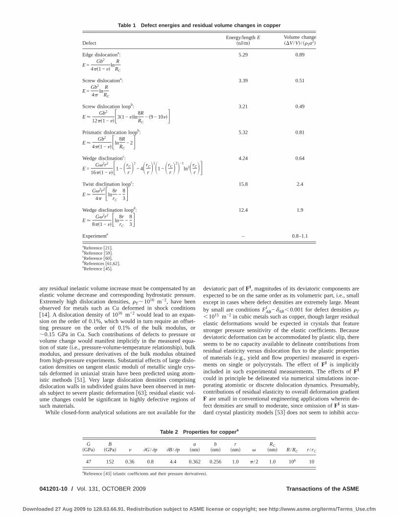
3.7 Examples. Table 1 presents strain energies per unit linelength E of a number of defects: straight edge and screw disloca-tions discussed already in Sec. 3.5; circular screw and prismaticdislocation loops of radius R and core radius RC, and straightwedge disclinations and circular twist and wedge disclinationloops of Frank vector �, radius r, and core radius rC. Energies allcorrespond to defects in infinite, isotropic linear-elastic solids.Analytical formulas for energies follow from references quoted inTable 1, while normalized volume changes ��V /V� / ��Ta2� com-puted for copper follow from Eq. �68� for edge dislocations andfrom Eq. �62� for the other defects, using material properties listedin Table 2. For defects besides edge dislocations, strain energy istreated as deviatoric, leading to the linear relationship betweenvolume change and defect density given in Eq. �64�. This is arigorous assertion for screw dislocation loops and twist disclina-tion loops but not prismatic loops or wedge disclinations, thoughit has been used elsewhere for these defects �18,61� and shouldprovide a reasonable approximation to the volume change formany metals �10�, including Cu. Again, �T is the line length perunit reference volume of the defect, and a is the lattice spacing ofthe conventional unit cell in a perfect crystal at room temperature.Experimental results for polycrystalline Cu are provided for com-parison �45�; the range of volume changes reported in Table 1 forthe experiments corresponds to estimates of dislocation line lengthfrom energy measurements after plastic compressive strains rang-ing from 0.3 to 0.7. The nature of the defects �e.g., edge versusscrew and straight lines versus loops� was not reported in thatexperimental investigation.
From Table 1, the normalized volume changes predicted forvarious kinds of dislocations agree with the experimental findingswithin a factor of �2 and are very close for edge dislocations andprismatic loops. Volume changes per unit defect length in Cu arepositive �i.e., defects cause expansion� and small. For example, a1% volume increase would require an immense density of edgedislocations on the order of �T�0.01a−2�1017 m−2, correspond-ing to an average dislocation spacing on the order of 10a. Forsmall volume changes ��V /V�1%�, det FI should be expected
provide an accurate approximation of J according to Eq. �82�.Disclination energies and volume changes are comparable to thosefor dislocations for the small cutoff radii or small loops consid-ered here �r=10rC� but would diverge quickly at large distances rfrom the core of straight disclinations or for larger disclinationloops. Elastic anisotropies of individual grains, defect core ener-gies, and interaction energies among defects and between defectsand the external boundary of the body �e.g., image forces� areneglected in this application of the model; such effects presum-ably contribute to discrepancies between theory and experiment.
The results of Table 1, along with experimental data summa-rized by Wright �11�, suggest that volume changes resulting fromresidual elasticity associated with dislocations should be small inmetallic crystals of cubic symmetry deformed in compression orshear to strains on the order of unity, under quasistatic conditions.The experimental results in Table 1 �45� correspond to dislocationdensities on the order of �T�1015 m−2, leading to volumechanges on the order of �V /V�10−4. Such small volume changeswould seem inconsequential in the context of measured yieldproperties of materials in unconfined loading, when specimens arefree to expand or contract laterally. However, under lateral con-finement, for example, uniaxial strain conditions occurring inshock loading �14,15�, small volume changes can drastically af-fect the measured hydrostatic pressure. Volume changes cannot be
accommodated by dislocation glide, as noted in Sec. 2.1; hence,OCTOBER 2009, Vol. 131 / 041201-9
license or copyright; see http://www.asme.org/terms/Terms_Use.cfm
aeEo�st�vtmfctidaus
0
Downlo
ny residual inelastic volume increase must be compensated by anlastic volume decrease and corresponding hydrostatic pressure.xtremely high dislocation densities, �T�1016 m−2, have beenbserved for metals such as Cu deformed in shock conditions14�. A dislocation density of 1016 m−2 would lead to an expan-ion on the order of 0.1%, which would in turn require an offset-ing pressure on the order of 0.1% of the bulk modulus, or
0.15 GPa in Cu. Such contributions of defects to pressure orolume change would manifest implicitly in the measured equa-ion of state �i.e., pressure-volume-temperature relationship�, bulkodulus, and pressure derivatives of the bulk modulus obtained
rom high-pressure experiments. Substantial effects of large dislo-ation densities on tangent elastic moduli of metallic single crys-als deformed in uniaxial strain have been predicted using atom-stic methods �51�. Very large dislocation densities comprisingislocation walls in subdivided grains have been observed in met-ls subject to severe plastic deformation �63�; residual elastic vol-me changes could be significant in highly defective regions ofuch materials.
While closed-form analytical solutions are not available for the
Table 1 Defect energies and re
Defect
Edge dislocationa:
E =Gb2
4��1 − ��ln
R
RC
Screw dislocationa:
E =Gb2
4�ln
R
RC
Screw dislocation loopb:
E �Gb2
12��1 − ���3�1 − ��ln8R
RC− �9 − 10���
Prismatic dislocation loopb:
E �Gb2
4��1 − ���ln8R
RC− 2�
Wedge disclinationc:
E =G�2r2
16��1 − ���1 − �rC
r�2
− 4�rC
r�2�1 − �rC
r�2�−1
ln2�rC
r
Twist disclination loopc:
E �G�2r2
4��ln
8r
rC−
8
3�
Wedge disclination loopd:
E �G�2r2
8��1 − ���ln8r
rC−
8
3�
Experimente
aReference �21�.bReference �59�.cReference �60�.dReferences �61,62�.eReference �45�.
Table 2 Prope
G�GPa�
B�GPa� � �G /�p �B /�p
a�nm
47 152 0.36 0.8 4.4 0.3
a
Reference �43� �elastic coefficients and their pressure derivatives41201-10 / Vol. 131, OCTOBER 2009
aded 27 Aug 2009 to 128.63.66.91. Redistribution subject to ASME
deviatoric part of FI, magnitudes of its deviatoric components areexpected to be on the same order as its volumetric part, i.e., smallexcept in cases where defect densities are extremely large. Meantby small are conditions FAB
I −�AB�0.001 for defect densities �T�1015 m−2 in cubic metals such as copper, though larger residualelastic deformations would be expected in crystals that featurestronger pressure sensitivity of the elastic coefficients. Becausedeviatoric deformation can be accommodated by plastic slip, thereseems to be no capacity available to delineate contributions fromresidual elasticity versus dislocation flux to the plastic propertiesof materials �e.g., yield and flow properties� measured in experi-ments on single or polycrystals. The effect of FI is implicitlyincluded in such experimental measurements. The effects of FI
could in principle be delineated via numerical simulations incor-porating atomistic or discrete dislocation dynamics. Presumably,contributions of residual elasticity to overall deformation gradientF are small in conventional engineering applications wherein de-fect densities are small to moderate, since omission of FI in stan-dard crystal plasticity models �53� does not seem to inhibit accu-
ual volume changes in copper
Energy/length E�nJ/m�
Volume change��V /V� / ��Ta2�
5.29 0.89
3.39 0.51
3.21 0.49
5.32 0.81
4.24 0.64
15.8 2.4
12.4 1.9
– 0.8–1.1
s for coppera
b�nm�
r�nm� �
RC�nm� R /RC r /rC
0.256 1.0 � /2 1.0 106 10
sid
��
rtie
�
62
�.
Transactions of the ASME
license or copyright; see http://www.asme.org/terms/Terms_Use.cfm
rdtFe�s
4
cdaasv
vnrdcsm
w
m
f
P
Ia
mats
l
w
iic
bc
J
Downlo
acy of such models. On the other hand, interacting stress fields ofislocations strongly affect yield and strain hardening �57�; fur-hermore, spatial gradients of FI need not always be small even ifI itself is small relative to the unit tensor. Gradients of residuallastic deformation, in addition to gradients of lattice rotation30�, can be associated with the density of geometrically neces-ary dislocations and kinematic hardening in metals �34,35�.
Atomistic ApproachThe volume element of the crystalline solid is now treated as a
ollection L of discrete atoms rather than a continuum. Prior toiscussion in Sec. 4.4 of the self-equilibrated, relaxed intermedi-te configuration and means to compute FI entering Eq. �17�tomically, relevant background discussion pertinent to latticetatics, atomic stress measures, and atomic interactions are pro-ided in Secs. 4.1–4.3.
4.1 Lattice Statics. The atoms occupy a perfect lattice in theolume element corresponding to configuration B0 of Fig. 1. Asoted already in Eq. �1�, the position of each atom i in configu-ation B0 is expressed by vector R�i�, with angular brackets used toenote the atomic labels. The position vector of atom i in currentonfiguration B is r�i�. In classical Newtonian mechanics de-cribed via rectangular Cartesian coordinates, the balance of linearomentum for particle i is
m�i�r�i�a = f �i�
a + f �i�a �83�
here m�i� is the mass of atom i, f �i�a are the external forces that
ay be explicitly time dependent, and f �i�a are the conservative
orces satisfying
f �i�a = − �ab ��
�r�i�b �84�
otential energy � is a function of all atomic coordinates:
� = ��r�i��i�L �85�
n the context of lattice statics, external and internal forces bal-nce. In the absence of external forces,
��
�r�i�b = 0 �86�
eaning that the vector sum of all interatomic forces acting ontom i is zero. A more specific form of the potential that maintainsranslational invariance of the energy depends only on the relativeeparation between each pair of atoms r�ij�=r�j�−r�i�:
� = ��r�ij��i,j�Li�j
�87�
eading to
f �ij�a = �ab ��
�r�ij�b �88�
ith f �ij�a components of an interaction force between atoms i and
j. In general, Eq. �87� accounts for three-body and higher-ordernteractions, for example, angles subtended by vectors r�ij� amongnteracting sets of three or more atoms. For materials featuringentral force interactions only, Eqs. �87� and �88� reduce to
� = ��r�ij��i,j�Li�j
, r�ij� = �r�ij� • r�ij��1/2, f�ij� =��
�r�ij�
r�ij�
r�ij�
�89�
4.2 Atomic Stress Measures. A number definitions of stressased on atomic quantities have been suggested �46,50,64�. In the
ontext of lattice statics �i.e., null atomic velocities and accelera-ournal of Engineering Materials and Technology
aded 27 Aug 2009 to 128.63.66.91. Redistribution subject to ASME
tions�, the average virial stress for a group of atoms is often con-sidered equivalent to the average Cauchy stress �46�:
� =1
2��i�j
r�ij� � f�ij� �90�
where � is the total volume occupied by the group L of atoms,i.e., the sum of all atomic volumes, in spatial configuration B. Thesummation in Eq. �90� is, in fact, a double sum, proceeding overall pairs of distinct �i� j� atoms. The factor of 2 arises in Eq. �90�because in the notation used here, summation proceeds over alli� j, r�ij�=−r�ji�, and f�ij�=−f�ji�. For systems with central forceinteractions only, symmetry of the stress tensor follows triviallyfrom Eqs. �89� and �90�:
ab =1
2��i�j
1
r�ij�
��
�r�ij�r�ij�
a r�ij�b =
1
2��i�j
1
r�ij�
��
�r�ij�r�ij�
b r�ij�a = ba
�91�
Now consider a homogeneous deformation F applied to all atomsin L, leading to r�ij�=FR�ij� �22,38�, with R�ij�=R�j�−R�i� fixedseparations between atoms of the reference lattice. Rigid bodytranslations are omitted in this homogeneous deformation. Lettingthe average strain energy per unit reference volume of the lattice� satisfy �0��F�=��r�ij��F ,R�ij���, the analog of Eq. �33� is
PaA =��
�FaA=
1
2�0�i�j
��
�r�ij�b
�r�ij�b
�FaA=
1
2�0�i�j
�ab ��
�r�ij�b R�ij�
A
�92�
where �0 is the total volume occupied by the atomic system in B0.�The atomic volume in a perfect lattice is equal to �0 divided bythe number of atoms comprising L.� Relation �92� is a conse-quence of the affine deformation of all atoms that results in�r�ij�
b /�FaA=�abR�ij�A . The average atomic Cauchy stress or average
static virial stress is then
ab = det�F.a−1A�PbAF.A
a =�0
� � 1
2�0�i�j
�bc ��
�r�ij�c R�ij�
A �F.Aa
=1
2��i�j
r�ij�a �bc ��
�r�ij�c �93�
in agreement with Eq. �90�. The present analysis applies only tomaterials described by potentials of the general form �87� and forwhich stress relations �90�, �92�, and �93� are appropriate. Forexample, metals that can be modeled by combinations of pairpotentials and multibody potentials such as the embedded atommethod are included. Not admitted are piezoelectric crystals �e.g.,noncentrosymmetric ionic solids�, some of whose atoms �sublat-tices� may display a relative shift when polarized, and for whichhyperelastic relation �92� may not be sufficient. In these cases,atomic vibrations may provide insight into origins of stress andmaterial coefficients �22,38,65�. Also excluded from the analysisare noncentrosymmetric polyatomic lattices such as diamond andsilicon that may incur inner displacements �54�.
4.3 Harmonic and Anharmonic Interactions. Expandingthe potential energy of Eq. �87� in a series about the reference
state, letOCTOBER 2009, Vol. 131 / 041201-11
license or copyright; see http://www.asme.org/terms/Terms_Use.cfm
wlase
FstotdS�t
a
�
S�
S
g
Ia
0
Downlo
� = �0 + �i�j� ��
�r�ij�a �
r=R
q�ij�a +
1
2!�i�j
k�l
� �2�
�r�ij�a � r�kl�
b �r=R
q�ij�a q�kl�
b
+1
3! �i�j
k�l
m�n
� �3�
�r�ij�a � r�kl�
b � r�mn�c �
r=R
q�ij�a q�kl�
b q�mn�c + . . . �94�
here �0 is the cohesive or ground state energy of the referenceattice, q�ij�=r�ij�−R�ij� is the relative displacement betweentomic pairs, and the second term vanishes by Eqs. �86� and �88�ince the reference configuration B0 is explicitly chosen free ofxternal and internal forces:
� ��
�r�ij�a �
r=R
= 0 �95�
ollowing the scheme first used in Eq. �90�, repeated use of theummation symbol is omitted in Eq. �94�. Hence, summation inhe second term on the right side of Eq. �94� applies over two setsf repeated atomic labels, that in the third term over four sets, andhat in the fourth term over six sets. The energy � in Eq. �92�iffers from the strain energy per reference volume �0 used inec. 3 by the constant �0 /�0=�−�0, since continuum energy31� vanishes in the reference state. Introducing the matrix nota-ion
H�ijkl�ab = �ac�bd� �2�
�r�ij�c � r�kl�
d �r=R
�96��H�ijklmn�abc = �ad�be�cf �3�
�r�ij�d � r�kl�
e � r�mn�f �
r=R
nd noting that �q�kl�a /�r�kl�
b =�.ba , the average spatial stress of Eqs.
90� and �93� becomes
ab =1
2��i�j
k�l
r�ij�a H�ijkl�
bc �cdq�kl�d
+1
4� �i�j
k�l
m�n
r�ij�a H�ijklmn�
bce �cdq�kl�d �efq�mn�
f + . . . �97�
ince r�ij�=−r�ji�, the atomic stiffness matrix in the first of Eq.96� exhibits the natural symmetries
H�ijkl�ab = H�jilk�
ab = H�klij�ba = − H�jikl�
ab = − H�ijlk�ab = − H�klji�
ba �98�
imilar symmetries can be deduced for H�ijklmn�abc . Under a homo-
eneous deformation q�ij�= �F−1�R�ij�,
PaA =1
2�0�i�j
k�l
H�ijkl�ab �bcq�kl�
c R�ij�A
+1
4�0�i�j
k�l
m�n
H�ijklmn�abc �bdq�kl�
d �ceq�mn�e R�ij�
A + . . . �99�
n the harmonic approximation, products of order higher than 2 in
tomic displacements q are dropped from Eq. �94�, leading to41201-12 / Vol. 131, OCTOBER 2009
aded 27 Aug 2009 to 128.63.66.91. Redistribution subject to ASME
f �ij�a = �
k�l
H�ijkl�ab �bcq�kl�
c , ab =1
2��i�j
k�l
r�ij�a H�ijkl�
bc �cdq�kl�d
�100�
PaA =1
2�0�i�j
k�l
H�ijkl�ab �bcq�kl�
c R�ij�A
A two-point elasticity tensor �i.e., tangent modulus� for homoge-neous deformations can be found as
AaAbB =�PaA
�FbB=
�2�
�FaA � FbB=
1
2�0�i�j
k�l
�2�
�r�ij�c � r�kl�
d
�r�ij�c
�FaA
�r�kl�d
�FbB
=1
2�0�i�j
k�l
�2�
�r�ij�c � r�kl�
d �acR�ij�A �bdR�kl�
B �101�
Defining the finite strain measure EAB= �F.Aa �abF.B
b −�AB� /2 andnoting that
�2�
�EAB � ECD= �AaBcD −
��
�EBD�ac�F.a
−1AF.c−1C �102�
the average second-order elastic constants in the reference stateare defined from atomic quantities as
CABCD = �.aA �.c
CAaBcD F=1 =1
2�0�i�j
k�l
H�ijkl�ab �.a
A R�ij�B �.b
CR�kl�D
�103�
and clearly depend only on the harmonic part of the potential.Similarly, for third-order coefficients
AaAbBcC =�2PaA
�FbB � FcC=
�3�
�FaA � FbB � FcC
=1
2�0�i�j
k�l
m�n
�3�
�r�ij�d � r�kl�
e � r�mn�f �adR�ij�
A �beR�kl�B �cfR�mn�
C
�104�
Differentiating Eq. �102� with respect to E gives
�3�
�EAE � EBD � ECG= �AaAbBcC −
�2�
�EAB � ECF�abF.F
c
−�2�
�EAC � EBF�acF.F
b −�2�
�EAF � EBC�bcF.F
a ��F.a
−1EF.b−1DF.c
−1G �105�
Third-order elastic constants at the reference state are then
Transactions of the ASME
license or copyright; see http://www.asme.org/terms/Terms_Use.cfm
Ri�msmttitvgewpasisttHt3
LSrt�ge
prpu
iemmucdfb
s
J
Downlo
CABCDEF = AaAbCcE F=1�.aB �.b
D�.cF − CACEF�BD − CAECD�BF
− CABCE�DF
=1
2�0�i�j
k�l
m�n
H�ijklmn�abc R�ij�
A R�kl�C R�mn�
E �.aB �.b
D�.cF
−1
2�0�i�j
k�l
H�ijkl�ab �.a
A R�ij�C �.b
E R�kl�F �BD
−1
2�0�i�j
k�l
H�ijkl�ab �.a
A R�ij�E �.b
CR�kl�D �BF
−1
2�0�i�j
k�l
H�ijkl�ab �.a
A R�ij�B �.b
CR�kl�E �DF �106�
elation �106� indicates that third-order elastic constants dependn part on anharmonic terms in the potential �48,66�. Derivations99�, �101�, �103�, �104�, and �106� rely on uniformity of the ato-istic deformation, such that the relationship between current po-
ition vector r and reference position vector R is linear in theapping F. In this atomistic context, F is regarded as a linear
ransformation for the primitive Bravais lattice vectors �e.g., akino FL in Eq. �12��, and though it acts uniformly over atoms in anndividual element of reference volume �0, F or FL need not behe gradient of any macroscopic vector field spanning neighboringolume elements �51�. In contrast, determination of deformationradient measures for individual atoms of a body undergoing het-rogeneous deformation is more involved �67�. Expansion �94�,hile generic in the sense that many types of interactions �e.g.,airwise and multibody, and central and noncentral forces� aredmitted, may be cumbersome for computation of elastic con-tants for specific potentials not expressed explicitly in terms ofnteratomic separation vectors. For example, expressions forecond- and third-order elastic constants for cubic crystals ob-ained from the embedded atom method are available �68� inerms of derivatives with respect to scalar interatomic distances.owever, these expressions �68� for second- and third-order elas-
ic constants analogously contain derivatives of up to orders 2 and, respectively, of the potential functions.
4.4 Net Residual Deformation in a Self-Equilibrated
attice. Now consider self-equilibrated configuration B of Fig. 1.lip may have occurred in achieving this configuration from theeference state, but atoms occupy perfect lattice sites apart fromhe effects of any defects remaining within the element that eitheri� are also present in the reference configuration B0 or �ii� areenerated during the course of plastic deformation. Not consid-red here is the �former� class of defects present in B0. Although
ositions of specific atoms differ in configurations B0 and B as aesult of translations by Burgers vectors of dislocations that haveassed through the volume element, coordinates R�i� can still besed to identify positions of atoms occupying perfect lattice sites
n B �51�. The volume element may either be treated as an isolatednsemble of atoms with free boundaries or as part of an infiniteedium with a periodic defect distribution. The former case isore consistent with the fundamental definition of the isolated
nloaded configuration �26� given in Sec. 2, while the latterase—which implicitly includes the effects of image forces ofefects in neighboring volume elements—may be more practicalrom the standpoint of lattice statics calculations with periodicoundary conditions �69�. Previous definitions for achieving
˜
lipped configuration B discussed in Sec. 2.1 still apply here, butournal of Engineering Materials and Technology
aded 27 Aug 2009 to 128.63.66.91. Redistribution subject to ASME
dislocation fluxes contributing to the plastic deformation are nowinterpreted in terms of velocities of atoms comprising each linedefect rather than as continuum quantities. External forces vanish
by definition in B, as do dynamics �i.e., atomic velocities andaccelerations�, so lattice statics relation �86� applies for a self-equilibrated lattice. However, because of the presence of defects,
the stable total energy of the ensemble L of atoms in B is a localminimum �47,69� as opposed to the global minimum correspond-ing to perfect lattice in B0. This implies that some atoms occupymetastable positions; some interatomic �i.e., internal� forces do
not vanish within the element in B as they do in B0 according to
Eq. �95�; and the potential energy in B exceeds �0. Existence of ametastable state of local minimum energy results from a lack ofstrict convexity of the total potential energy.
The position of atom i in configuration B is denoted by r�i�.
Because B is self-equilibrated, average static atomic stress mea-sures vanished by definition:
ab =1
2��i�j
r�ij�a �bc ��
� r�ij�c = 0, PaA =
1
2�0�i�j
�ab ��
� r�ij�b R�ij�
A = 0
�107�
with �= J�0 the system volume in B, � the potential energy ofEq. �87�, and r�ij�=r�j�−r�i�. Because atomic coordinates are notmapped homogeneously from their positions in B0 to their posi-
tions in B, the average first Piola–Kirchhoff stress measure in thesecond of Eq. �107� does not follow from a linear transformationsuch as used in the chain rule in Eq. �92�; it is instead introducedas a fundamental definition. Equation �107� contains discrete ana-logs of continuum relations �23� and �29�. Here as in Eq. �94�, thepotential energy is expanded in a series about a perfect referenceconfiguration:
� = �0 +1
2�i�j
k�l
H�ijkl�ab �acq�ij�
c �bdq�kl�d
+1
6 �i�j
k�l
m�n
H�ijklmn�abc �adq�ij�
d �beq�kl�e �cfq�mn�
f + . . . �108�
with q�ij�=r�ij�−R�ij� the displacement difference between two at-oms in the defective lattice, and where Eqs. �95� and �96� havebeen used to define atomic stiffness coefficients in Eq. �108�. Sub-stituting Eq. �108� into the first of Eq. �107� and multiplying
through by J, the null average atomic stress relation becomes
0 = J fa =1
2�0�i�j
k�l
r�ij�f H�ijkl�
ab �bc
q�kl�c
+1
4�0�i�j
k�l
m�n
r�ij�f H�ijklmn�
abc �bd
q�kl�d �
ceq�mn�
e + . . . �109�
Just as in Eqs. �36�–�40�, vanishing of the average symmetricstress measured in the reference configuration leads by definitionto six equations for six unknown components of the symmetricdeformation map FI. Identifying harmonic terms in the atomicdefinition of the average stress with linear terms in the continuum
elastic definition of the average stress:OCTOBER 2009, Vol. 131 / 041201-13
license or copyright; see http://www.asme.org/terms/Terms_Use.cfm
t
wsp
wfcebaa
ew
q
FduF�ca
rvf
ttio
itpvvStbtta�
0
Downlo
�110�
he following definition emerges:
CABCD�FCDI − �CD� =
1
2�0�.f
A�.aB �
i�j
k�l
r�ij�f H�ijkl�
ab �bcq�kl�c
= −1
4�0�.f
A�.aB �
i�j
k�l
m�n
r�ij�f H�ijklmn�
abc �bdq�kl�d �ceq�mn�
e
− . . . �111�
ith the second equality following directly from Eq. �109�. As-uming that the reference stiffness of the perfect lattice CABCD isositive definite,
FCDI = �CD
−1
�0SCDAB���.f
A�.aB /4� �
i�j
k�l
m�n
r�ij�f H�ijklmn�
abc �bdq�kl�d �ceq�mn�
e + . . . ��112�
here the compliance SCDAB satisfies Eq. �41� and can be foundrom inverting the second-order reference moduli, the latter eitheromputed using Eq. �103� and the chain rule or computed fromxpressions available for particular potentials �68�. The series inrackets on the right of Eq. �112� accounts for anharmonic inter-ctions, and includes terms of order 2 and higher in relativetomic displacements q�ij�
a in the locally deformed, yet self-
quilibrated, defective lattice. For harmonic lattice statics, inhich case H�ijklmn�
abc =0 and/or quadratic and higher-order terms in
�ij�a are dropped, the bracketed series degenerates to zero and
CDI =�CD, analogously to linear continuum description �38�. Theefinition for FCD
I implied by the first of Eq. �111�, while notnique, is motivated by the corresponding continuum definition
CDI =V−1�x�C,D�dV=V−1SCDABCABEF�x�E,F�dV in Eqs. �35� and
40�. Following Sec. 3.6, the first-order accurate residual volume
hange is J=� /�0�det�FCDI ��F.C
IC−�.CC +1, where continuum
nd discrete measures of reference and intermediate volumes are
elated, respectively, by �0=V and �=V+�V. Calculation of thisolume change does not require identification of a bounding sur-ace delineating the volume occupied by the atoms in configura-
ion B, i.e., the atoms can occupy an arbitrary shape so long asheir interaction forces self-equilibrate. If such a surface can bedentified in a lattice statics calculation, for example, an ensemblef atoms in a defective state contained within a hexahedral bound-
ng box, it should be possible to compute � trivially �i.e., � ishen the volume of the box� and then compare the results with theredictions of Eq. �112�, so long as the average static virial stressanishes over the defective ensemble of atoms. An apparent ad-antage of the atomistic approach over the continuum approach ofec. 3 is that effects of defect cores are accurately incorporated in
he former, presuming that the atomic potential is sufficiently ro-ust to address defect core structures. An apparent disadvantage ishat solutions to Eq. �112� must be computed numerically, whilehe continuum elastic approach �8,43,44� provides convenientnalytical formulas for volume changes such as Eqs. �61� and
74�.41201-14 / Vol. 131, OCTOBER 2009
aded 27 Aug 2009 to 128.63.66.91. Redistribution subject to ASME
5 ConclusionsA three-term decomposition for finite multiplicative elastoplas-
ticity of a volume element of a crystalline solid has been de-scribed. Isochoric plastic deformation arises from displacementdiscontinuities such as those resulting from cumulative slip ofdislocations. Lattice deformation consists of two parts: �i� thatarising from recoverable straining due to external loading androtation of the lattice vectors and �ii� that arising from residualelasticity present when the volume element is self-equilibrated.Local displacement gradient fields within the element contributingto the latter �i.e., contributing to the average residual elastic strain�are conjugate to local elastic stress fields associated with latticedefects, for example, eigenstresses of dislocation and disclinationlines and loops. Two methods are used to quantify the averageresidual elastic strain. The first treats the body as a nonlinearhyperelastic solid with spatially constant moduli. In this case, thestrain energy is expanded in a series of up to order 3 in displace-ment gradients. An integral equation for the average residual elas-tic strain is obtained from the equilibrium conditions requiring theaverage stress to vanish. It follows that this average residual strainvanishes identically only when terms of order 3 are discarded, i.e.,when the body is treated as linear elastic. The second methodfollows from treating the body as a set of discrete atoms in thecontext of molecular or lattice statics. The potential energy isexpanded in a series about a reference state, wherein interatomicforces and average atomic stresses �i.e., average static virial stresscomponents� vanish. When the series contains only terms of up toorder 2 in relative interatomic displacements �i.e., harmonic latticestatics�, average dimensional changes of the lattice consisting ofan ensemble of atoms in a defective arrangement are negligibleaccording to the definitions used here. On the other hand, whenanharmonic terms are retained in the series expansion of the po-tential energy, average dimensional changes do not always vanishidentically. Particular attention has been given to average volumechanges resulting from strain energy of line defects in an exter-nally unstressed body, and examples for dislocation and disclina-tion lines and loops have been tabulated and compared with ex-perimental data for copper. Theoretical predictions andexperimental measurements for volumetric expansion resultingfrom dislocation and disclination lines or loops agree within abouta factor of 2. Because average residual elastic deformation resultsfrom nonlinear elastic effects, i.e., products of displacement gra-dients of orders 2 and higher in the continuum treatment, or fromanharmonic effects, i.e., nonlinear force-displacement relations inthe atomistic treatment, the contribution of average residual elas-tic deformation to the total deformation gradient will generally besmall in conventional engineering applications wherein defectdensities remain small to moderate, as observed experimentallyfor volume changes in metallic crystals deformed quasistaticallyto macroscopic shear or compressive strains on the order of unity.However, for situations in which defect densities are extremelylarge, such as severe plastic deformation processes or shock load-ing, the theory suggests that the net contribution of residual elas-ticity from defects, especially volume changes, to the overall de-formation gradient could affect measured properties such as theapparent bulk modulus and its pressure derivatives.
References�1� Orowan, E., 1940, “Problems of Plastic Gliding,” Proc. Phys. Soc. London,
52, pp. 8–22.�2� Mura, T., 1968, “Continuum Theory of Dislocations and Plasticity,” Mechan-
ics of Generalized Continua, E. Kroner, ed., Springer-Verlag, New York, pp.269–278.
�3� Bilby, B. A., Gardner, L. R. T., and Stroh, A. N., 1957, “Continuous Distri-butions of Dislocations and the Theory of Plasticity,” Proceedings of the NinthInternational Congress of Applied Mechanics, Bruxelles, Vol. 8, pp. 35–44.
�4� Teodosiu, C., 1970, “A Dynamic Theory of Dislocations and Its Applicationsto the Theory of the Elastic-Plastic Continuum,” Fundamental Aspects of Dis-location Theory, J. A. Simmons, R. De Wit, and R. Bullough, eds., U.S. Natl.Bur. Stand. Spec. Publ. No. 317, Washington, DC, Vol. II, pp. 837–876.
�5� Rice, J. R., 1971, “Inelastic Constitutive Relations for Solids: An Internal
Transactions of the ASME
license or copyright; see http://www.asme.org/terms/Terms_Use.cfm
J
Downlo
Variable Theory and Its Application to Metal Plasticity,” J. Mech. Phys. Solids,19, pp. 433–455.
�6� De Wit, R., 1973, “Theory of Disclinations II, III, IV,” J. Res. Nat. BureauStandards A Phys. Chem., 77, pp. 49–100, 359–368, 607–658.
�7� Mura, T., 1982, Micromechanics of Defects in Solids, Martinus Nijhoff, Dor-drecht.
�8� Zener, C., 1942, “Theory of Lattice Expansion Introduced by Cold Work,”Trans. Am. Inst. Min. Metall. Engrs., 147, pp. 361–368.
�9� Schmid, E., and Boas, I. W., 1950, Plasticity of Crystals, Chapman and Hall,London.
�10� Holder, J., and Granato, A. V., 1969, “Thermodynamic Properties of SolidsContaining Defects,” Phys. Rev., 182, pp. 729–741.
�11� Wright, T. W., 1982, “Stored Energy and Plastic Volume Change,” Mech.Mater., 1, pp. 185–187.
�12� Taheri, M., Weiland, H., and Rollett, A., 2006, “A Method of MeasuringStored Energy Macroscopically Using Statistically Stored Dislocations inCommercial Purity Aluminum,” Metall. Mater. Trans. A, 37, pp. 19–25.
�13� Rosakis, P., Rosakis, A. J., Ravichandran, G., and Hodowany, J., 2000, “AThermodynamic Internal Variable Model for the Partition of Plastic Work IntoHeat and Stored Energy in Metals,” J. Mech. Phys. Solids, 48, pp. 581–607.
�14� Rohatgi, A., and Vecchio, K. S., 2002, “The Variation of Dislocation Densityas a Function of the Stacking Fault Energy in Shock-Deformed FCC Materi-als,” Mater. Sci. Eng., A, 328, pp. 256–266.
�15� Clayton, J. D., 2009, “A Continuum Description of Nonlinear Elasticity, Slipand Twinning, With Application to Sapphire,” Proc. R. Soc. London, Ser. A,465, pp. 307–334.
�16� Clayton, J. D., Bammann, D. J., and McDowell, D. L., 2005, “A GeometricFramework for the Kinematics of Crystals With Defects,” Philos. Mag., 85,pp. 3983–4010.
�17� Clayton, J. D., McDowell, D. L., and Bammann, D. J., 2006, “Modeling Dis-locations and Disclinations With Finite Micropolar Elastoplasticity,” Int. J.Plast., 22, pp. 210–256.
�18� Li, J. C. M., and Gilman, J. T., 1970, “Disclination Loops in Polymers,” J.Appl. Phys., 41, pp. 4248–4256.
�19� Eshelby, J. D., 1954, “Distortion of a Crystal Caused by Point Imperfections,”J. Appl. Phys., 25, pp. 255–261.
�20� Eshelby, J. D., 1956, “The Continuum Theory of Lattice Defects,” Solid StatePhysics 3, F. Seitz and D. Turnbull, eds., Academic, New York, pp. 79–144.
�21� Hirth, J. P., and Lothe, J., 1982, Theory of Dislocations, Krieger, Malabar, FL.�22� Born, M., and Huang, K., 1954, Dynamical Theory of Crystal Lattices, Oxford
University Press, Oxford.�23� Ericksen, J. L., 1984, “The Cauchy and Born Hypothesis for Crystals,” Phase
Transformations and Material Instabilities in Solids, M. E. Gurtin, ed., Aca-demic, New York, pp. 61–78.
�24� Kroner, E., 1960, “Allgemeine kontinuumsthoerie der versetzungen undeigenspannungen,” Arch. Ration. Mech. Anal., 4, pp. 273–334.
�25� Lee, E. H., 1969, “Elastic-Plastic Deformation at Finite Strains,” ASME J.Appl. Mech., 36, pp. 1–6.
�26� Eckart, C., 1948, “The Thermodynamics of Irreversible Processes IV. TheTheory of Elasticity and Anelasticity,” Phys. Rev., 73, pp. 373–382.
�27� Kroner, E., and Seeger, A., 1959, “Nicht-Lineare Elastizitatstheorie der Verset-zungen und Eigenspannungen,” Arch. Ration. Mech. Anal., 3, pp. 97–119.
�28� Willis, J. R., 1967, “Second-Order Effects of Dislocations in Anisotropic Crys-tals,” Int. J. Eng. Sci., 5, pp. 171–190.
�29� Teodosiu, C., 1982, Elastic Models of Crystal Defects, Springer-Verlag, Berlin.�30� Nye, J. F., 1953, “Some Geometrical Relations in Dislocated Crystals,” Acta
Metall., 1, pp. 153–162.�31� Kondo, K., 1964, “On the Analytical and Physical Foundations of the Theory
of Dislocations and Yielding by the Differential Geometry of Continua,” Int. J.Eng. Sci., 2, pp. 219–251.
�32� Steinmann, P., 1996, “Views on Multiplicative Elastoplasticity and the Con-tinuum Theory of Dislocations,” Int. J. Eng. Sci., 34, pp. 1717–1735.
�33� Shizawa, K., and Zbib, H., 1999, “A Thermodynamical Theory of Plastic Spinand Internal Stress With Dislocation Density Tensor,” ASME J. Eng. Mater.Technol., 121, pp. 247–253.
�34� Bammann, D. J., 2001, “A Model of Crystal Plasticity Containing a NaturalLength Scale,” Mater. Sci. Eng., A, 309–310, pp. 406–410.
�35� Regueiro, R. A., Bammann, D. J., Marin, E. B., and Garikipati, K., 2002, “ANonlocal Phenomenological Anisotropic Finite Deformation Plasticity ModelAccounting for Dislocation Defects,” ASME J. Eng. Mater. Technol., 124, pp.380–387.
�36� Clayton, J. D., Bammann, D. J., and McDowell, D. L., 2004, “A MultiscaleGradient Theory for Elastoviscoplasticity of Single Crystals,” Int. J. Eng. Sci.,42, pp. 427–457.
�37� Clayton, J. D., Chung, P. W., Grinfeld, M. A., and Nothwang, W. D., 2008,“Kinematics, Electromechanics, and Kinetics of Dielectric and PiezoelectricCrystals With Lattice Defects,” Int. J. Eng. Sci., 46, pp. 10–30.
�38� Huang, K., 1950, “On the Atomic Theory of Elasticity,” Proc. R. Soc. London,
Ser. A, 203, pp. 178–194.ournal of Engineering Materials and Technology
aded 27 Aug 2009 to 128.63.66.91. Redistribution subject to ASME
�39� Lardner, R. W., 1969, “Dislocation Dynamics and the Theory of the Plasticityof Single Crystals,” Z. Angew. Math. Phys., 20, pp. 514–529.
�40� Kratochvil, J., 1972, “Finite Strain Theory of Inelastic Behavior of CrystallineSolids,” Foundations of Plasticity, A. Sawczuk, ed., Noordhoff, Leyden, pp.401–415.
�41� Hartley, C. S., 2003, “A Method for Linking Thermally Activated DislocationMechanisms of Yielding With Continuum Plasticity Theory,” Philos. Mag.,83, pp. 3783–3808.
�42� Clayton, J. D., and McDowell, D. L., 2003, “A Multiscale Multiplicative De-composition for Elastoplasticity of Polycrystals,” Int. J. Plast., 19, pp. 1401–1444.
�43� Seeger, A., and Haasen, P., 1958, “Density Changes of Crystals ContainingDislocations,” Philos. Mag., 3, pp. 470–475.
�44� Toupin, R. A., and Rivlin, R. S., 1960, “Dimensional Changes in CrystalsCaused by Dislocations,” J. Math. Phys., 1, pp. 8–15.
�45� Glarebrough, L. M., Hargreaves, M. E., and West, G. W., 1957, “The Densityof Dislocations in Compressed Copper,” Acta Metall., 5, pp. 738–740.
�46� Zhou, M., 2003, “A New Look at the Atomic Level Virial Stress: OnContinuum-Molecular System Equivalence,” Proc. R. Soc. London, Ser. A,459, pp. 2347–2392.
�47� Gallego, R., and Ortiz, M., 1993, “A Harmonic/Anharmonic Energy PartitionMethod for Lattice Statics Computations,” Modell. Simul. Mater. Sci. Eng., 1,pp. 417–436.
�48� Maugin, G. A., 1999, Nonlinear Waves in Elastic Crystals, Oxford UniversityPress, New York.
�49� Yavari, A., Ortiz, M., and Bhattacharya, K., 2007, “A Theory of AnharmonicLattice Statics for Analysis of Defective Crystals,” J. Elast., 86, pp. 41–83.
�50� Horstemeyer, M. F., and Baskes, M. I., 1999, “Atomic Finite DeformationSimulations: A Discussion on Length Scale Effects in Relation to MechanicalStress,” ASME J. Eng. Mater. Technol., 121, pp. 114–119.
�51� Clayton, J. D., and Chung, P. W., 2006, “An Atomistic-to-Continuum Frame-work for Nonlinear Crystal Mechanics Based on Asymptotic Homogeniza-tion,” J. Mech. Phys. Solids, 54, pp. 1604–1639.
�52� Zbib, H. M., Rubia, T. D. L., and Bulatov, V., 2002, “A Multiscale Model ofPlasticity Based on Discrete Dislocation Dynamics,” ASME J. Eng. Mater.Technol., 124, pp. 78–87.
�53� Asaro, R. J., 1983, “Crystal Plasticity,” ASME J. Appl. Mech., 50, pp. 921–934.
�54� Tadmor, E. B., Smith, G. S., Bernstein, N., and Kaxiras, E., 1999, “MixedFinite Element and Atomistic Formulation for Complex Crystals,” Phys. Rev.B, 59, pp. 235–245.
�55� Hill, R., 1972, “On Constitutive Macro-Variables for Heterogeneous Solids atFinite Strain,” Proc. R. Soc. London, Ser. A, 326, pp. 131–147.
�56� Clayton, J. D., and McDowell, D. L., 2004, “Homogenized Finite Elastoplas-ticity and Damage: Theory and Computations,” Mech. Mater., 36, pp. 799–824.
�57� Hull, D., and Bacon, D. J., 1984, Introduction to Dislocations, 3rd ed.,Butterworth-Heinemann, Oxford.
�58� Thurston, R. N., 1974, “Waves in Solids,” Handbuch der Physik, Vol. VIa/4,C. Truesdell, ed., Springer-Verlag, Berlin, pp. 109–308.
�59� Owen, D. J. R., and Mura, T., 1967, “Dislocation Configurations in CylindricalCoordinates,” J. Appl. Phys., 38, pp. 2818–2825.
�60� Huang, W., and Mura, T., 1970, “Elastic Fields and Energies of a CircularEdge Disclination and a Straight Screw Disclination,” J. Appl. Phys., 41, pp.5175–5179.
�61� Liu, G. C. T., and Li, J. C. M., 1971, “Strain Energies of Disclination Loops,”J. Appl. Phys., 42, pp. 3313–3315.
�62� Kuo, H. H., and Mura, T., 1972, “Elastic Field and Strain Energy of a CircularWedge Disclination,” J. Appl. Phys., 43, pp. 1454–1457.
�63� Hughes, D. A., Hansen, N., and Bammann, D. J., 2003, “Geometrically Nec-essary Boundaries, Incidental Dislocation Boundaries, and Geometrically Nec-essary Dislocations,” Scr. Mater., 48, pp. 147–153.
�64� Zimmerman, J. A., Webb, E. B., III, Hoyt, J. J., Jones, R. E., Klein, P. A., andBammann, D. J., 2004, “Calculation of Stress in Atomistic Simulation,” Mod-ell. Simul. Mater. Sci. Eng., 12, pp. S319–S332.
�65� Mindlin, R. D., 1972, “Elasticity, Piezoelectricity, and Crystal Lattice Dynam-ics,” J. Elast., 2, pp. 217–282.
�66� Thurston, R. N., and Brugger, K., 1964, “Third-Order Elastic Constants andthe Velocity of Small Amplitude Elastic Waves in Homogeneously StressedMedia,” Phys. Rev., 133, pp. A1604–A1610.
�67� Zimmerman, J. A., Bammann, D. J., and Gao, H., 2009, “Deformation Gradi-ents for Continuum Mechanical Analysis of Atomistic Simulations,” Int. J.Solids Struct., 46, pp. 238–253.
�68� Chantasiriwan, S., and Milstein, F., 1996, “Higher-Order Elasticity of CubicMetals in the Embedded-Atom Method,” Phys. Rev. B, 53, pp. 14080–14088.
�69� Chung, P. W., and Clayton, J. D., 2007, “Multiscale Modeling of Point andLine Defects in Cubic Lattices,” Int. J. Multiscale Comp. Eng., 5, pp. 203–
226.OCTOBER 2009, Vol. 131 / 041201-15
license or copyright; see http://www.asme.org/terms/Terms_Use.cfm
NO. OF COPIES ORGANIZATION
1 DEFENSE TECHNICAL (PDF INFORMATION CTR only) DTIC OCA 8725 JOHN J KINGMAN RD STE 0944 FORT BELVOIR VA 22060-6218 1 DIRECTOR US ARMY RESEARCH LAB IMNE ALC HRR 2800 POWDER MILL RD ADELPHI MD 20783-1197 1 DIRECTOR US ARMY RESEARCH LAB RDRL CIM L 2800 POWDER MILL RD ADELPHI MD 20783-1197 1 DIRECTOR US ARMY RESEARCH LAB RDRL CIM P 2800 POWDER MILL RD ADELPHI MD 20783-1197
ABERDEEN PROVING GROUND 1 DIR USARL RDRL CIM G (BLDG 4600)
NO. OF NO. OF COPIES ORGANIZATION COPIES ORGANIZATION
1 DIRECTOR US ARMY RESEARCH LAB RDRL CI R NAMBURU 2800 POWDER MILL RD ADELPHI MD 20783-1197
ABERDEEN PROVING GROUND
45 DIR USARL RDRL CIH C P CHUNG D GROVE J KNAP RDRL SL R COATES RDRL WM B FORCH S KARNA J MCCAULEY T WRIGHT RDRL WMS T JONES RDRL WMM A J ANDZELM W NOTHWANG RDRL WMM D B CHEESEMAN G GAZONAS RDRL WMT A R DONEY S SCHOENFELD RDRL WMT C T BJERKE T FARRAND M FERMEN-COKER S SEGLETES B SCHUSTER A TANK W WALTERS C WILLIAMS RDR WMT D S BILYK D CASEM J CLAYTON (10 CPS) D DANDEKAR N GNIAZDOWSKI M GREENFIELD Y HUANG R KRAFT B LOVE
M RAFTENBERG E RAPACKI M SCHEIDLER T WEERASOORIYA
INTENTIONALLY LEFT BLANK.