FINAL Zucker UNION PACIFIC RAILROAD SANTA TERESA TERMINAL ... · UNION PACIFIC RAILROAD SANTA...
25
UNION PACIFIC RAILROAD SANTA TERESA TERMINAL PROJECT AUTHORS Mike Zucker, PE – Program Manager Design – Union Pacific Railroad 1400 Douglas Street, STOP 0910, Omaha, NE 68179 Tel.: (402) 544-3281 – Fax: (402) 501-1761 Greg Clark, PE – Facility & Utility Design Program Manager – Union Pacific Railroad 1400 Douglas Street, STOP 0910, Omaha, NE 68179 Tel.: (402) 544-3270 – Fax: (402) 501-3033 David Olson, PE – Associate Vice President – Wilson & Company, Inc., Engineers & Architects 11516 Miracle Hills Drive, Suite 102, Omaha, NE 68154 Tel.: (402) 896-6100 – Fax: (402) 496-4070 NUMBER OF WORDS Not including acknowledgements: 4,166 ABSTRACT Located at the eastern end of the Union Pacific Railroad’s (UP) historic Sunset Route, the Santa Teresa Terminal is situated at the crossroads of freight movement from west coast ports to major consumer markets located anywhere from Atlanta to Chicago. This 2,200-acre facility features a run-through fueling facility, intermodal ramp, and a location for a future block swap yard. The facility secures southern New Mexico and west Texas with a prosperous future as a leader in the goods movement industry. © AREMA 2014 1
Transcript of FINAL Zucker UNION PACIFIC RAILROAD SANTA TERESA TERMINAL ... · UNION PACIFIC RAILROAD SANTA...
UNION PACIFIC RAILROAD SANTA TERESA TERMINAL PROJECT
AUTHORS
Mike Zucker, PE – Program Manager Design – Union Pacific Railroad
1400 Douglas Street, STOP 0910, Omaha, NE 68179
Tel.: (402) 544-3281 – Fax: (402) 501-1761
Greg Clark, PE – Facility & Utility Design Program Manager – Union Pacific Railroad
1400 Douglas Street, STOP 0910, Omaha, NE 68179
Tel.: (402) 544-3270 – Fax: (402) 501-3033
David Olson, PE – Associate Vice President – Wilson & Company, Inc., Engineers & Architects
11516 Miracle Hills Drive, Suite 102, Omaha, NE 68154
Tel.: (402) 896-6100 – Fax: (402) 496-4070
NUMBER OF WORDS
Not including acknowledgements: 4,166
ABSTRACT
Located at the eastern end of the Union Pacific Railroad’s (UP) historic Sunset Route, the Santa Teresa Terminal is situated at the crossroads of freight movement from west coast ports to major consumer markets located anywhere from Atlanta to Chicago. This 2,200-acre facility features a run-through fueling facility, intermodal ramp, and a location for a future block swap yard. The facility secures southern New Mexico and west Texas with a prosperous future as a leader in the goods movement industry.
© AREMA 2014 1
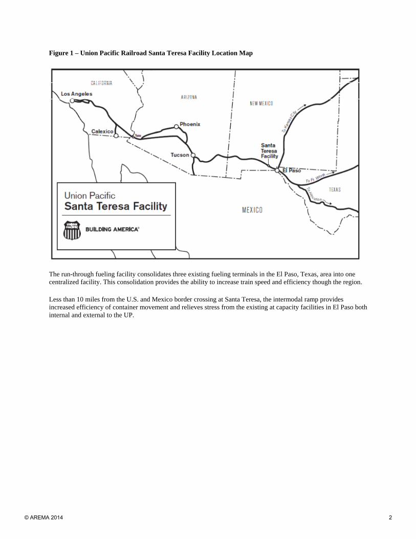
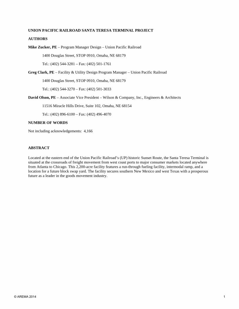
Figure 1 – Union Pacific Railroad Santa Teresa Facility Location Map
The run-through fueling facility consolidates three existing fueling terminals in the El Paso, Texas, area into one centralized facility. This consolidation provides the ability to increase train speed and efficiency though the region.
Less than 10 miles from the U.S. and Mexico border crossing at Santa Teresa, the intermodal ramp provides increased efficiency of container movement and relieves stress from the existing at capacity facilities in El Paso both internal and external to the UP.
© AREMA 2014 2
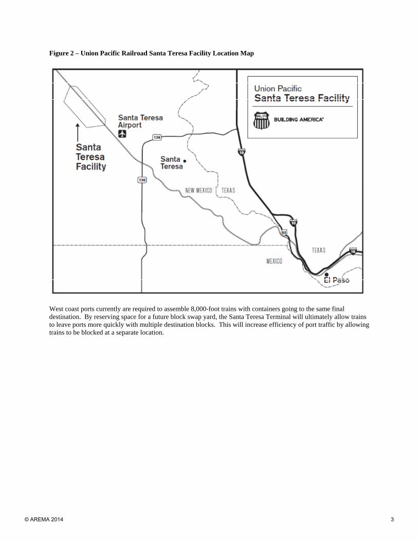
Figure 2 – Union Pacific Railroad Santa Teresa Facility Location Map
West coast ports currently are required to assemble 8,000-foot trains with containers going to the same final destination. By reserving space for a future block swap yard, the Santa Teresa Terminal will ultimately allow trains to leave ports more quickly with multiple destination blocks. This will increase efficiency of port traffic by allowing trains to be blocked at a separate location.
© AREMA 2014 3
INTRODUCTION
Three facilities in one make the UP Santa Teresa Terminal a world-class facility. This facility not only enhances railroad operations within the region, but serves as an economic driver for the surrounding communities for decades to come. Approximately 3,000 jobs were created by the end of construction and more than 200 permanent jobs are now in place to operate the facility with up to 600 additional jobs in the future; and countless jobs, businesses and developments have been created and enhanced through the growth of infrastructure within the region.
Figure 3 – Union Pacific Railroad Santa Teresa Terminal Aerial Photo
Stakeholder buy-in at all levels of this project aided in its successful completion. All team members practiced open communication—UP; design engineers; contractors, suppliers and vendors; local, state, and federal governmental agencies; utility providers; fuel suppliers; and private community residents. All parties worked together to identify and overcome potential obstacles to keep this project moving forward during design, permitting and construction. This was a “can do” project energized by “can do” attitudes.
© AREMA 2014 4
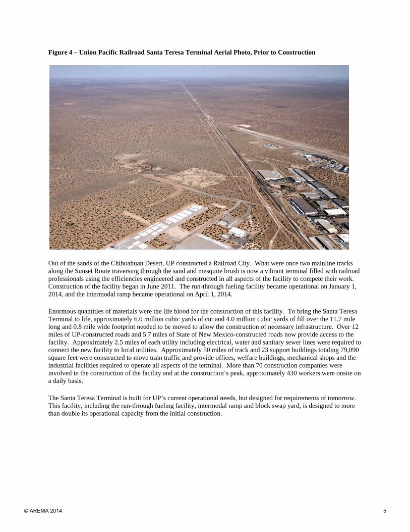
Figure 4 – Union Pacific Railroad Santa Teresa Terminal Aerial Photo, Prior to Construction
Out of the sands of the Chihuahuan Desert, UP constructed a Railroad City. What were once two mainline tracks along the Sunset Route traversing through the sand and mesquite brush is now a vibrant terminal filled with railroad professionals using the efficiencies engineered and constructed in all aspects of the facility to compete their work. Construction of the facility began in June 2011. The run-through fueling facility became operational on January 1, 2014, and the intermodal ramp became operational on April 1, 2014.
Enormous quantities of materials were the life blood for the construction of this facility. To bring the Santa Teresa Terminal to life, approximately 6.0 million cubic yards of cut and 4.0 million cubic yards of fill over the 11.7 mile long and 0.8 mile wide footprint needed to be moved to allow the construction of necessary infrastructure. Over 12 miles of UP-constructed roads and 5.7 miles of State of New Mexico-constructed roads now provide access to the facility. Approximately 2.5 miles of each utility including electrical, water and sanitary sewer lines were required to connect the new facility to local utilities. Approximately 50 miles of track and 23 support buildings totaling 79,090 square feet were constructed to move train traffic and provide offices, welfare buildings, mechanical shops and the industrial facilities required to operate all aspects of the terminal. More than 70 construction companies were involved in the construction of the facility and at the construction’s peak, approximately 430 workers were onsite on a daily basis.
The Santa Teresa Terminal is built for UP’s current operational needs, but designed for requirements of tomorrow. This facility, including the run-through fueling facility, intermodal ramp and block swap yard, is designed to more than double its operational capacity from the initial construction.
© AREMA 2014 5
Run-Through Fueling Facility
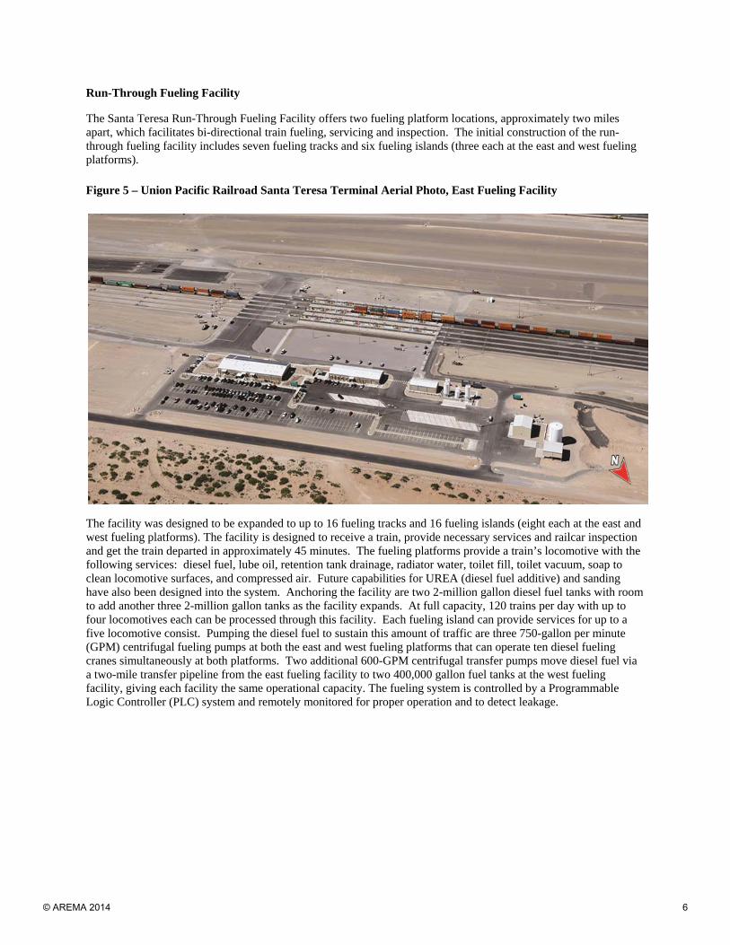
The Santa Teresa Run-Through Fueling Facility offers two fueling platform locations, approximately two miles apart, which facilitates bi-directional train fueling, servicing and inspection. The initial construction of the run-through fueling facility includes seven fueling tracks and six fueling islands (three each at the east and west fueling platforms).
Figure 5 – Union Pacific Railroad Santa Teresa Terminal Aerial Photo, East Fueling Facility
The facility was designed to be expanded to up to 16 fueling tracks and 16 fueling islands (eight each at the east and west fueling platforms). The facility is designed to receive a train, provide necessary services and railcar inspection and get the train departed in approximately 45 minutes. The fueling platforms provide a train’s locomotive with the following services: diesel fuel, lube oil, retention tank drainage, radiator water, toilet fill, toilet vacuum, soap to clean locomotive surfaces, and compressed air. Future capabilities for UREA (diesel fuel additive) and sanding have also been designed into the system. Anchoring the facility are two 2-million gallon diesel fuel tanks with room to add another three 2-million gallon tanks as the facility expands. At full capacity, 120 trains per day with up to four locomotives each can be processed through this facility. Each fueling island can provide services for up to a five locomotive consist. Pumping the diesel fuel to sustain this amount of traffic are three 750-gallon per minute (GPM) centrifugal fueling pumps at both the east and west fueling platforms that can operate ten diesel fueling cranes simultaneously at both platforms. Two additional 600-GPM centrifugal transfer pumps move diesel fuel via a two-mile transfer pipeline from the east fueling facility to two 400,000 gallon fuel tanks at the west fueling facility, giving each facility the same operational capacity. The fueling system is controlled by a Programmable Logic Controller (PLC) system and remotely monitored for proper operation and to detect leakage.
© AREMA 2014 6
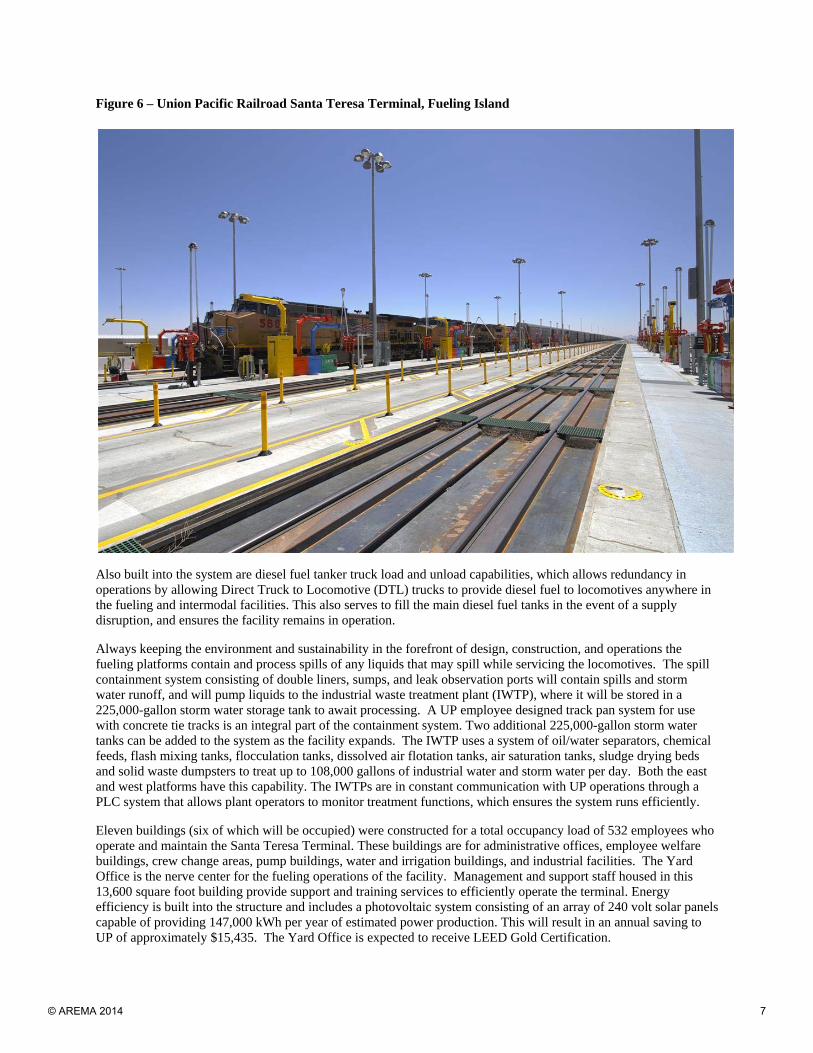
Figure 6 – Union Pacific Railroad Santa Teresa Terminal, Fueling Island
Also built into the system are diesel fuel tanker truck load and unload capabilities, which allows redundancy in operations by allowing Direct Truck to Locomotive (DTL) trucks to provide diesel fuel to locomotives anywhere in the fueling and intermodal facilities. This also serves to fill the main diesel fuel tanks in the event of a supply disruption, and ensures the facility remains in operation.
Always keeping the environment and sustainability in the forefront of design, construction, and operations the fueling platforms contain and process spills of any liquids that may spill while servicing the locomotives. The spill containment system consisting of double liners, sumps, and leak observation ports will contain spills and storm water runoff, and will pump liquids to the industrial waste treatment plant (IWTP), where it will be stored in a 225,000-gallon storm water storage tank to await processing. A UP employee designed track pan system for use with concrete tie tracks is an integral part of the containment system. Two additional 225,000-gallon storm water tanks can be added to the system as the facility expands. The IWTP uses a system of oil/water separators, chemical feeds, flash mixing tanks, flocculation tanks, dissolved air flotation tanks, air saturation tanks, sludge drying beds and solid waste dumpsters to treat up to 108,000 gallons of industrial water and storm water per day. Both the east and west platforms have this capability. The IWTPs are in constant communication with UP operations through a PLC system that allows plant operators to monitor treatment functions, which ensures the system runs efficiently.
Eleven buildings (six of which will be occupied) were constructed for a total occupancy load of 532 employees who operate and maintain the Santa Teresa Terminal. These buildings are for administrative offices, employee welfare buildings, crew change areas, pump buildings, water and irrigation buildings, and industrial facilities. The Yard Office is the nerve center for the fueling operations of the facility. Management and support staff housed in this 13,600 square foot building provide support and training services to efficiently operate the terminal. Energy efficiency is built into the structure and includes a photovoltaic system consisting of an array of 240 volt solar panels capable of providing 147,000 kWh per year of estimated power production. This will result in an annual saving to UP of approximately $15,435. The Yard Office is expected to receive LEED Gold Certification.
© AREMA 2014 7
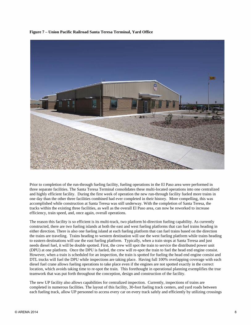
Figure 7 – Union Pacific Railroad Santa Teresa Terminal, Yard Office
Prior to completion of the run-through fueling facility, fueling operations in the El Paso area were performed in three separate facilities. The Santa Teresa Terminal consolidates these multi-located operations into one centralized and highly efficient facility. During the first week of operation the new run-through facility fueled more trains in one day than the other three facilities combined had ever completed in their history. More compelling, this was accomplished while construction at Santa Teresa was still underway. With the completion of Santa Teresa, the tracks within the existing three facilities, as well as the overall El Paso area, can now be reworked to increase efficiency, train speed, and, once again, overall operations.
The reason this facility is so efficient is its multi-track, two platform bi-direction fueling capability. As currently constructed, there are two fueling islands at both the east and west fueling platforms that can fuel trains heading in either direction. There is also one fueling island at each fueling platform that can fuel trains based on the direction the trains are traveling. Trains heading to western destination will use the west fueling platform while trains heading to eastern destinations will use the east fueling platform. Typically, when a train stops at Santa Teresa and just needs diesel fuel, it will be double spotted. First, the crew will spot the train to service the distributed power unit (DPU) at one platform. Once the DPU is fueled, the crew will re-spot the train to fuel the head end engine consist. However, when a train is scheduled for an inspection, the train is spotted for fueling the head end engine consist and DTL trucks will fuel the DPU while inspections are taking place. Having full 100% overlapping coverage with each diesel fuel crane allows fueling operations to take place even if the engines are not spotted exactly in the correct location, which avoids taking time to re-spot the train. This forethought in operational planning exemplifies the true teamwork that was put forth throughout the conception, design and construction of the facility.
The new UP facility also allows capabilities for centralized inspection. Currently, inspections of trains are completed in numerous facilities. The layout of this facility, 30-foot fueling track centers, and yard roads between each fueling track, allow UP personnel to access every car on every track safely and efficiently by utilizing crossings
© AREMA 2014 8
at each end of the fueling tracks. Bad order railcar setout tracks are located at each end of the facility to allow railcars that need further repairs to be setout while the rest of the train continues to the final destination.
The Santa Teresa facility is performing as planned. In the first few months of operations, the run-through fueling facility averaged 41 minutes for train inspections versus the historical average of 63 minutes at the existing UP Dallas Street facility in El Paso, Texas, a time savings of 22 minutes. The facility has also aided in increasing efficiency while fueling trains. Fuel only train times have been reduced from approximately 25 minutes at the existing UP Dallas Street facility to 17 minutes at Santa Teresa, a time savings of 8 minutes.
Intermodal Ramp
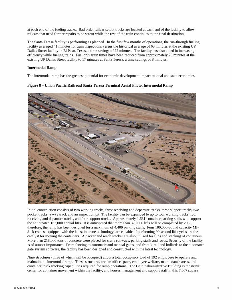
The intermodal ramp has the greatest potential for economic development impact to local and state economies.
Figure 8 – Union Pacific Railroad Santa Teresa Terminal Aerial Photo, Intermodal Ramp
Initial construction consists of two working tracks, three receiving and departure tracks, three support tracks, two pocket tracks, a wye track and an inspection pit. The facility can be expanded to up to four working tracks, four receiving and departure tracks, and four support tracks. Approximately 1,681 container parking stalls will support the anticipated 163,000 annual lifts. It is anticipated that more than 373,000 lifts will be completed by 2033; therefore, the ramp has been designed for a maximum of 4,400 parking stalls. Four 100,000-pound capacity MI-Jack cranes, equipped with the latest in crane technology, are capable of performing 90 second lift cycles are the catalyst for moving the containers. A packer and reach stacker are also utilized for flips and stacking of containers. More than 218,000 tons of concrete were placed for crane runways, parking stalls and roads. Security of the facility is of utmost importance. From fencing to automatic and manual gates, and from k-rail and bollards to the automated gate system software, the facility has been designed and constructed with the latest technology.
Nine structures (three of which will be occupied) allow a total occupancy load of 192 employees to operate and maintain the intermodal ramp. These structures are for office space, employee welfare, maintenance areas, and container/truck tracking capabilities required for ramp operations. The Gate Administrative Building is the nerve center for container movement within the facility, and houses management and support staff in this 7,667 square
© AREMA 2014 9
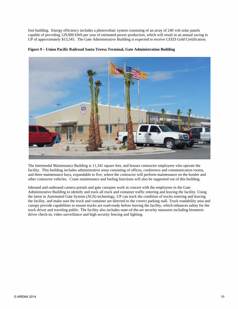
foot building. Energy efficiency includes a photovoltaic system consisting of an array of 240 volt solar panels capable of providing 129,000 kWh per year of estimated power production, which will result in an annual saving to UP of approximately $13,545. The Gate Administrative Building is expected to receive LEED Gold Certification.
Figure 9 – Union Pacific Railroad Santa Teresa Terminal, Gate Administration Building
The Intermodal Maintenance Building is 11,341 square feet, and houses contractor employees who operate the facility. This building includes administrative areas consisting of offices, conference and communication rooms, and three maintenance bays, expandable to five, where the contractor will perform maintenance on the hostler and other contractor vehicles. Crane maintenance and fueling functions will also be supported out of this building.
Inbound and outbound camera portals and gate canopies work in concert with the employees in the Gate Administrative Building to identify and track all truck and container traffic entering and leaving the facility. Using the latest in Automated Gate System (AGS) technology, UP can track the condition of trucks entering and leaving the facility, and make sure the truck and container are directed to the correct parking stall. Truck roadability area and canopy provide capabilities to ensure trucks are road-ready before leaving the facility, which enhances safety for the truck driver and traveling public. The facility also includes state-of-the-art security measures including biometric driver check-in, video surveillance and high security fencing and lighting.
© AREMA 2014 10
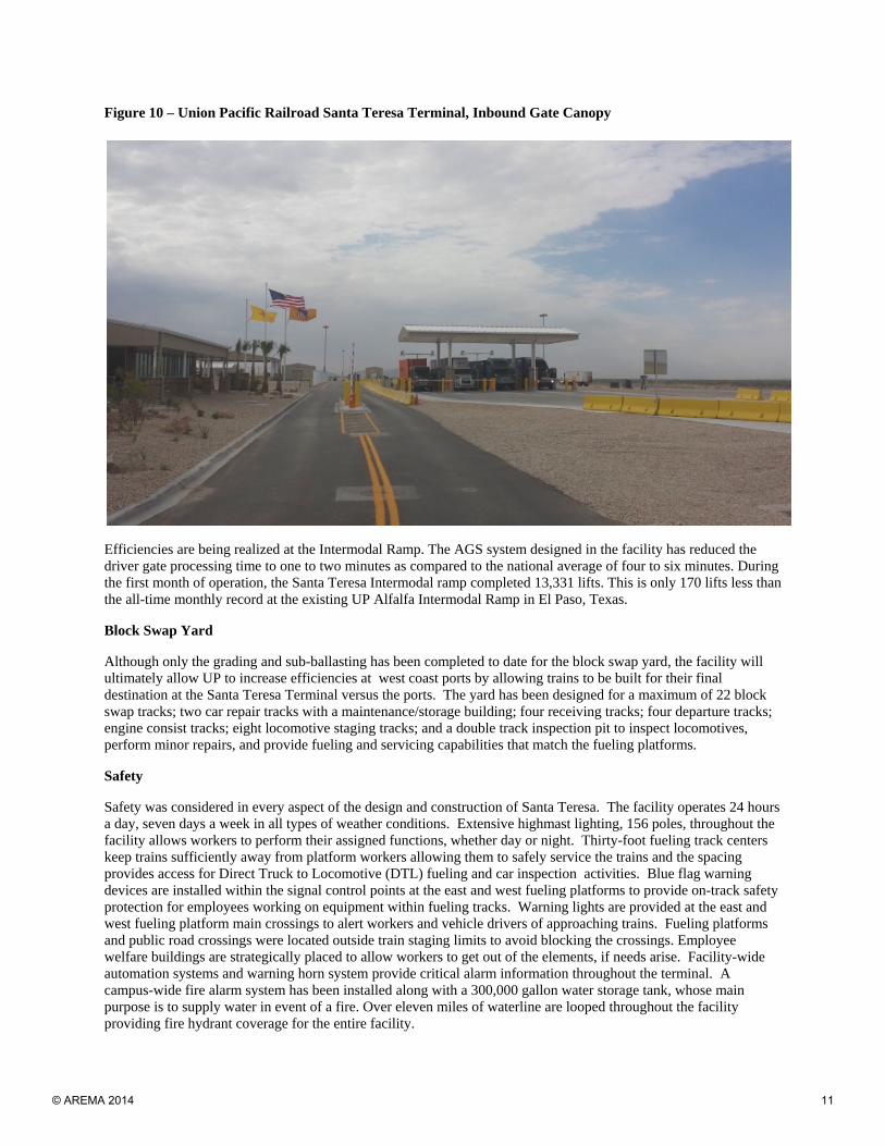
Figure 10 – Union Pacific Railroad Santa Teresa Terminal, Inbound Gate Canopy
Efficiencies are being realized at the Intermodal Ramp. The AGS system designed in the facility has reduced the driver gate processing time to one to two minutes as compared to the national average of four to six minutes. During the first month of operation, the Santa Teresa Intermodal ramp completed 13,331 lifts. This is only 170 lifts less than the all-time monthly record at the existing UP Alfalfa Intermodal Ramp in El Paso, Texas.
Block Swap Yard
Although only the grading and sub-ballasting has been completed to date for the block swap yard, the facility will ultimately allow UP to increase efficiencies at west coast ports by allowing trains to be built for their final destination at the Santa Teresa Terminal versus the ports. The yard has been designed for a maximum of 22 block swap tracks; two car repair tracks with a maintenance/storage building; four receiving tracks; four departure tracks; engine consist tracks; eight locomotive staging tracks; and a double track inspection pit to inspect locomotives, perform minor repairs, and provide fueling and servicing capabilities that match the fueling platforms.
Safety
Safety was considered in every aspect of the design and construction of Santa Teresa. The facility operates 24 hours a day, seven days a week in all types of weather conditions. Extensive highmast lighting, 156 poles, throughout the facility allows workers to perform their assigned functions, whether day or night. Thirty-foot fueling track centers keep trains sufficiently away from platform workers allowing them to safely service the trains and the spacing provides access for Direct Truck to Locomotive (DTL) fueling and car inspection activities. Blue flag warning devices are installed within the signal control points at the east and west fueling platforms to provide on-track safety protection for employees working on equipment within fueling tracks. Warning lights are provided at the east and west fueling platform main crossings to alert workers and vehicle drivers of approaching trains. Fueling platforms and public road crossings were located outside train staging limits to avoid blocking the crossings. Employee welfare buildings are strategically placed to allow workers to get out of the elements, if needs arise. Facility-wide automation systems and warning horn system provide critical alarm information throughout the terminal. A campus-wide fire alarm system has been installed along with a 300,000 gallon water storage tank, whose main purpose is to supply water in event of a fire. Over eleven miles of waterline are looped throughout the facility providing fire hydrant coverage for the entire facility.
© AREMA 2014 11
Other Infrastructure Highlights
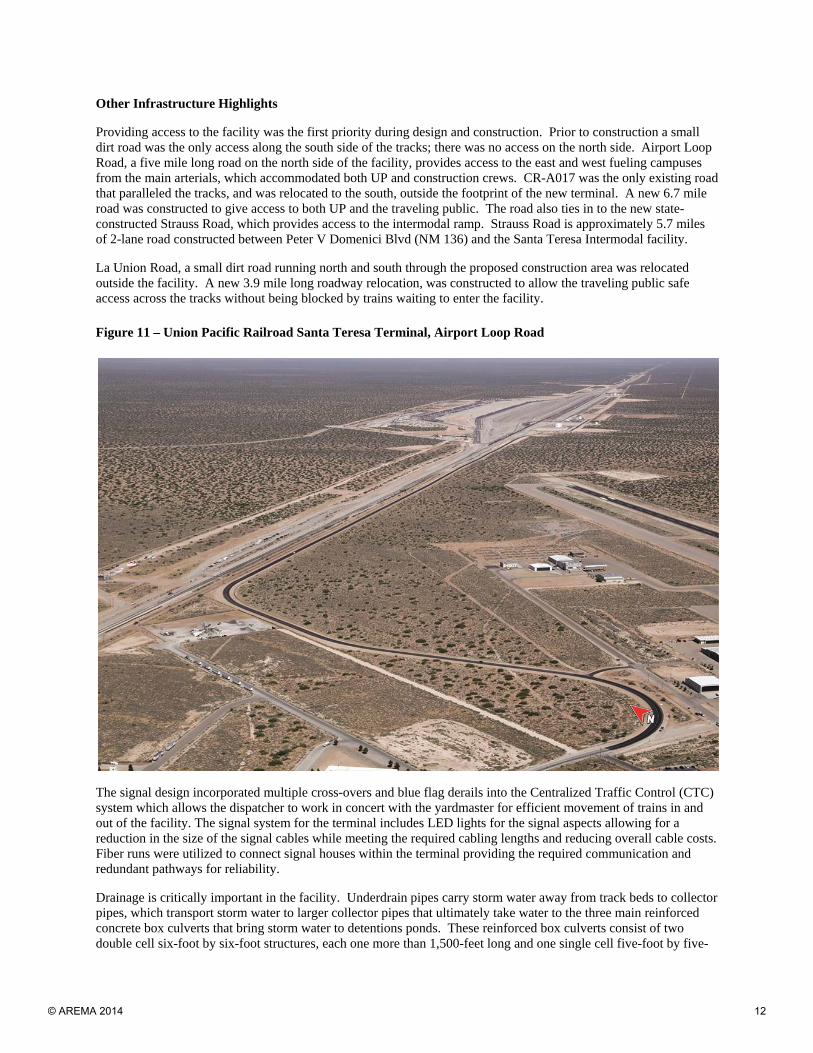
Providing access to the facility was the first priority during design and construction. Prior to construction a small dirt road was the only access along the south side of the tracks; there was no access on the north side. Airport Loop Road, a five mile long road on the north side of the facility, provides access to the east and west fueling campuses from the main arterials, which accommodated both UP and construction crews. CR-A017 was the only existing road that paralleled the tracks, and was relocated to the south, outside the footprint of the new terminal. A new 6.7 mile road was constructed to give access to both UP and the traveling public. The road also ties in to the new state-constructed Strauss Road, which provides access to the intermodal ramp. Strauss Road is approximately 5.7 miles of 2-lane road constructed between Peter V Domenici Blvd (NM 136) and the Santa Teresa Intermodal facility.
La Union Road, a small dirt road running north and south through the proposed construction area was relocated outside the facility. A new 3.9 mile long roadway relocation, was constructed to allow the traveling public safe access across the tracks without being blocked by trains waiting to enter the facility.
Figure 11 – Union Pacific Railroad Santa Teresa Terminal, Airport Loop Road
The signal design incorporated multiple cross-overs and blue flag derails into the Centralized Traffic Control (CTC) system which allows the dispatcher to work in concert with the yardmaster for efficient movement of trains in and out of the facility. The signal system for the terminal includes LED lights for the signal aspects allowing for a reduction in the size of the signal cables while meeting the required cabling lengths and reducing overall cable costs. Fiber runs were utilized to connect signal houses within the terminal providing the required communication and redundant pathways for reliability.
Drainage is critically important in the facility. Underdrain pipes carry storm water away from track beds to collector pipes, which transport storm water to larger collector pipes that ultimately take water to the three main reinforced concrete box culverts that bring storm water to detentions ponds. These reinforced box culverts consist of two double cell six-foot by six-foot structures, each one more than 1,500-feet long and one single cell five-foot by five-
© AREMA 2014 12
foot structure approximately 690-feet long. There are 13 on-site storm water detention ponds that have a combined storage area of 258 acre feet. During the week of September 12, 2013, the adequacy of the storm water design was put to the test. More than 15 inches of rain fell on the facility during two back-to-back 500 year storm events. The storm water system handled this rain event and allowed uninterrupted train traffic to run through the facility.
A 345 kV El Paso Electric (EPE) line providing electrical service to the El Paso metropolitan area was relocated prior to the completion of grading. Close coordination between UP and EPE was required to ensure uninterrupted electrical service along the transmission line and contractor safety for those people working closely to the line.
Electrical power to the facility is provided from a 23 kV power line from EPE, the local power company. During design, a second redundant electrical feeder route was investigated to avoid loss of power in case of an outage along the primary route. The redundant route was ultimately decided against in favor of other safeguarding systems including double-ended substations, dual transformers and loop feeders. Each critical facility is backed up with one of the 18 generators that will allow full operational capability if power is lost from the electrical feed. These solutions provided redundancy at a much more favorable cost.
Looped feeders provide redundancy inside the facility. Each facility primary transformer has two ways to supply power: loop design and sectionalizing cabinets and switches. The system is normally split; that is, half the facility is fed from one side of the dual substation and loop, and the other half is fed from the second substation transformer and loop. This reduces normal loads on the system by one-half, and reducing distribution losses by approximately one-fourth during normal operation. Approximately thirteen miles of underground duct bank was constructed to provide this level of redundancy. The underground ductbanks protect electrical and communication lines from severe weather and surface accidents further enhancing reliability.
To keep the facility in constant communication with on-site workers, crews and managers throughout the UP system, approximately 55 miles of single-mode fiber interconnects the yard and provides redundant connectivity to a majority of the network locations. There are 49 wireless hotspots throughout the fueling facility and intermodal ramp. Two microwave towers provide primary and backup telecom capabilities. In total, there are 108 telecom networked locations in 20 buildings and 88 outdoor enclosures. Within these locations, there are 521 networked devices. The telecom features also support 88 security cameras located in both the run-through fueling facility and intermodal ramp. The Santa Teresa facility is the largest single telecom project in UP’s history; this facility is truly on-line.
A tree sand wall, complete with an irrigation system, was installed along the east mainline tracks to provide protection from blowing sand. This system consists of a 50,000 gallon water tank, a pump house and approximately two miles of waterline which will help prevent sand from being deposited in the ballast section. The tree fence will ultimately increase the life of the ballast and reducing the amount of maintenance required.
CONCLUSION
The UP Santa Teresa facility embodies excellence in railroading engineering, construction and operation. Hundreds of people worked as a team to complete this railroad city on schedule and under budget. The operational, engineering and construction professionals who brought this facility to life created innovative solutions from years of experience and have delivered a highly efficient and expandable facility. Safety in design, construction and operations was and is the #1 priority for both the construction workers who built Santa Teresa to the day-to-day operators who keep the terminal moving safely. Finally, Santa Teresa has not only performed as originally planned, but has exceeded expectations because of the discipline, intensity, collaboration, shared ownership and solutions of its owner, designer, contractors, and all members of the team. This once-in-a-lifetime project team is proud to have set a new bar for railroad facility and operations excellence.
© AREMA 2014 13
LISTING OF TABLES AND FIGURES
Figure 1 – Union Pacific Railroad Santa Teresa Facility Location Map
Figure 2 – Union Pacific Railroad Santa Teresa Facility Location Map
Figure 3 – Union Pacific Railroad Santa Teresa Terminal Aerial Photo
Figure 4 – Union Pacific Railroad Santa Teresa Terminal Aerial Photo, Prior to Construction
Figure 5 – Union Pacific Railroad Santa Teresa Terminal Aerial Photo, East Fueling Facility
Figure 6 – Union Pacific Railroad Santa Teresa Terminal, Fueling Island
Figure 7 – Union Pacific Railroad Santa Teresa Terminal, Yard Office
Figure 8 – Union Pacific Railroad Santa Teresa Terminal Aerial Photo, Intermodal Ramp
Figure 9 – Union Pacific Railroad Santa Teresa Terminal, Gate Administration Building
Figure 10 – Union Pacific Railroad Santa Teresa Terminal, Inbound Gate Canopy
Figure 11 – Union Pacific Railroad Santa Teresa Terminal, Airport Loop Road
© AREMA 2014 14
Un
ion
Pac
ific
Rai
lro
ad
San
ta T
eres
a R
un
Th
rou
gh
Fu
elin
g F
acili
ty,
gg
y,In
term
od
al R
amp
an
d B
lock
Sw
ap Y
ard
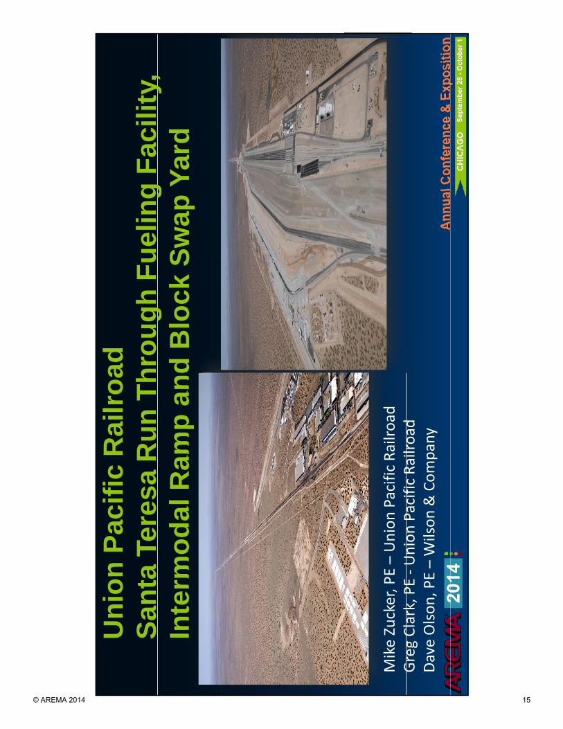
Mike Zucker, PE –Union Pacific Railroad
GCl
kPE
Ui
PifiR
ild
Greg Clark, PE ‐Union Pacific Railroad
Dave Olson, PE –Wilson & Company
© AREMA 2014 15
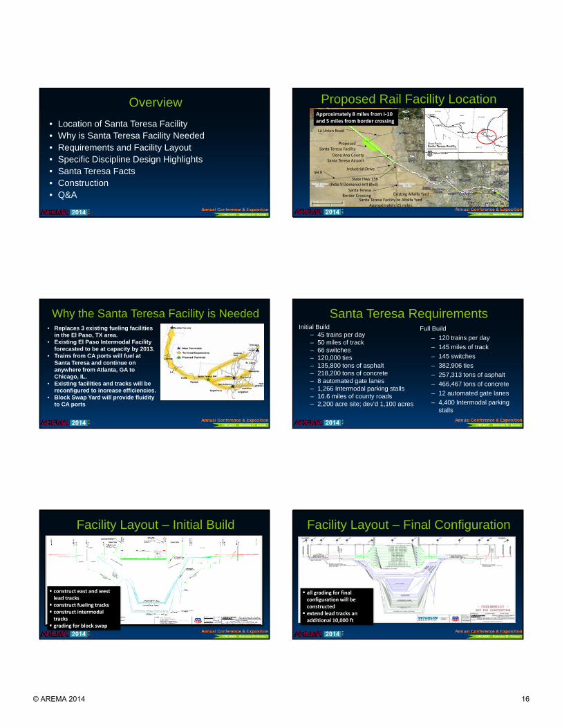
Overview
• Location of Santa Teresa Facility• Why is Santa Teresa Facility Needed• Requirements and Facility Layout• Specific Discipline Design Highlights• Santa Teresa Facts• Construction• Q&A
Proposed Rail Facility LocationProposed Rail Facility Location
ProposedSanta Teresa Facility
La Union Road
Approximately 8 miles from I‐10 and 5 miles from border crossing
State Hwy 136(Pete V Domenici Intl Blvd)
Industrial Drive
Santa TeresaBorder Crossing Existing Alfalfa Yard
Santa Teresa Facility to Alfalfa YardApproximately 25 miles
Dona Ana County Santa Teresa Airport
SH 9
Why the Santa Teresa Facility is Needed• Replaces 3 existing fueling facilities
in the El Paso, TX area.• Existing El Paso Intermodal Facility
forecasted to be at capacity by 2013.• Trains from CA ports will fuel at
Santa Teresa and continue onSanta Teresa and continue on anywhere from Atlanta, GA to Chicago, IL.
• Existing facilities and tracks will be reconfigured to increase efficiencies.
• Block Swap Yard will provide fluidity to CA ports
Santa Teresa RequirementsInitial Build
– 45 trains per day– 50 miles of track– 66 switches– 120,000 ties
135 800 t f h lt
Full Build
– 120 trains per day
– 145 miles of track
– 145 switches
382 906 ti– 135,800 tons of asphalt– 218,200 tons of concrete– 8 automated gate lanes– 1,266 Intermodal parking stalls– 16.6 miles of county roads– 2,200 acre site; dev’d 1,100 acres
– 382,906 ties
– 257,313 tons of asphalt
– 466,467 tons of concrete
– 12 automated gate lanes
– 4,400 Intermodal parking stalls
Facility Layout – Initial Build
construct east and west lead tracks construct fueling tracks construct intermodal tracks grading for block swap
Facility Layout – Final Configuration
all grading for final configuration will be constructed extend lead tracks an additional 10,000 ft
© AREMA 2014 16
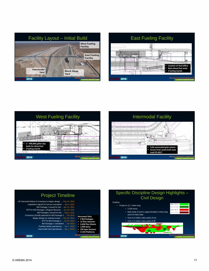
Facility Layout – Initial Build
East Fueling
West Fueling Facility
Intermodal Yard Block Swap
Yard
Facility
East Fueling Facility
Location of Yard Office Main diesel fuel tanks 3 fueling islands
West Fueling Facility
2 – 400,000 gallon day tanks for diesel fuel
3 fueling islands
Intermodal Facility
Fully automated gate system Access from newly built state
road CR‐A017
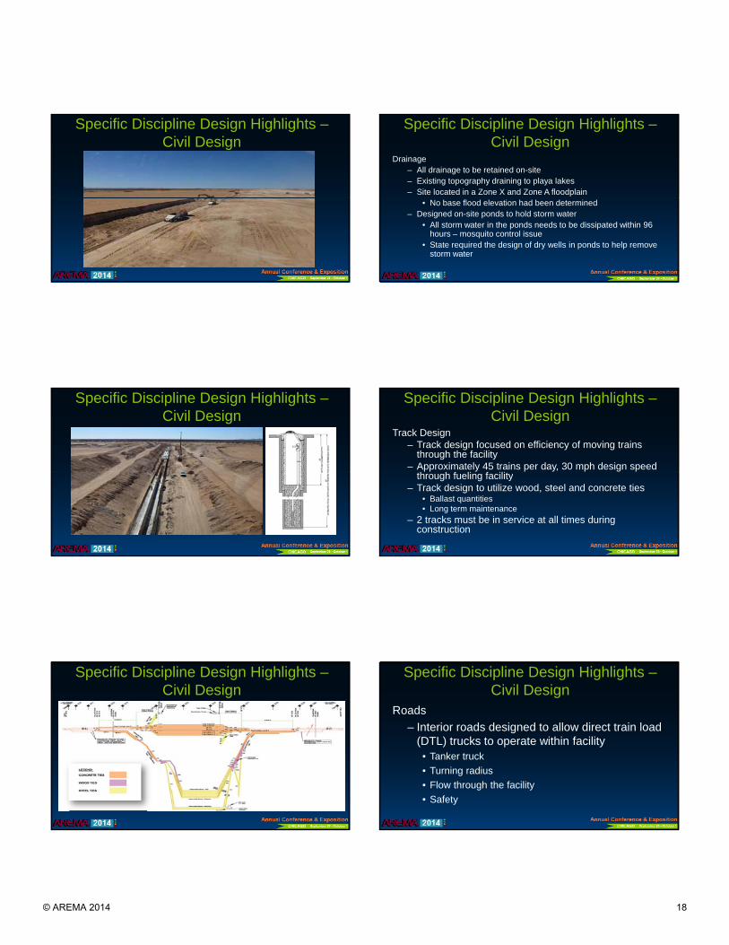
Project TimelineUP instructed Wilson & Company to began design … Sep 24, 2010
Legislation signed for fuel tax exemption … Apr 5, 2011
Bid Package 1 issued for bid … Apr 14, 2011
NTP for Bid Package 1 (Ragnar Benson) … Jun 20, 2011
Bid Package 2 issued for bid … Aug 3, 2011
Contractor (Sundt) selected for Bid Package 2 … Oct 2011
Began design on reduced scope … Dec 16, 2011
NTP for Bid Package 2 … Jul 23, 2012
Bid Package 1 completed … Jan 2013
Fueling Facility operational … Jan 1, 2014
Intermodal Yard operational … Apr 1, 2014
Document Stats 2 Bid Packages 12 Plan Volumes 2,630 Plan Sheets 1,950 items 335 Spec Sections 3 CAD Platforms
Specific Discipline Design Highlights –Civil Design
Grading
• Project is 11.7 miles long
• 2,200 acres
• Main body of yard is approximately 3 miles long
d 0 8 il idand 0.8 miles wide
• Over 6.0 million cubic yards of cut
• Over 4.0 million cubic yards of fill
© AREMA 2014 17
Specific Discipline Design Highlights –Civil Design
Specific Discipline Design Highlights –Civil Design
Drainage– All drainage to be retained on-site– Existing topography draining to playa lakes– Site located in a Zone X and Zone A floodplain
• No base flood elevation had been determined– Designed on-site ponds to hold storm water
• All storm water in the ponds needs to be dissipated within 96 hours – mosquito control issue
• State required the design of dry wells in ponds to help remove storm water
Specific Discipline Design Highlights –Civil Design
Specific Discipline Design Highlights –Civil Design
Track Design– Track design focused on efficiency of moving trains
through the facility– Approximately 45 trains per day, 30 mph design speed
h h f li f ilithrough fueling facility– Track design to utilize wood, steel and concrete ties
• Ballast quantities• Long term maintenance
– 2 tracks must be in service at all times during construction
Specific Discipline Design Highlights –Civil Design
Specific Discipline Design Highlights –Civil Design
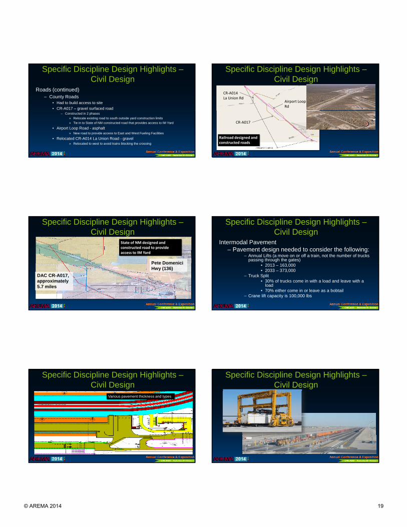
Roads
– Interior roads designed to allow direct train load (DTL) trucks to operate within facility( ) p y
• Tanker truck
• Turning radius
• Flow through the facility
• Safety
© AREMA 2014 18
Specific Discipline Design Highlights –Civil Design
Roads (continued)– County Roads
• Had to build access to site
• CR-A017 – gravel surfaced roadg– Constructed in 2 phases
» Relocate existing road to south outside yard construction limits
» Tie in to State of NM constructed road that provides access to IM Yard
• Airport Loop Road - asphalt» New road to provide access to East and West Fueling Facilities
• Relocated CR-A014 La Union Road - gravel» Relocated to west to avoid trains blocking the crossing
Specific Discipline Design Highlights –Civil Design
CR‐A014La Union Rd
Airport Loop Rd
Railroad designed and constructed roads
CR‐A017
Specific Discipline Design Highlights –Civil Design
State of NM designed and constructed road to provide access to IM Yard
Pete DomeniciPete Domenici Hwy (136)
DAC CR-A017,approximately 5.7 miles
Specific Discipline Design Highlights –Civil Design
Intermodal Pavement– Pavement design needed to consider the following:
– Annual Lifts (a move on or off a train, not the number of trucks passing through the gates)
• 2013 – 163,000• 2033 – 373,000
– Truck Split• 30% of trucks come in with a load and leave with a
load• 70% either come in or leave as a bobtail
– Crane lift capacity is 100,000 lbs
Specific Discipline Design Highlights –Civil Design
Various pavement thickness and types
Specific Discipline Design Highlights –Civil Design
© AREMA 2014 19
Specific Discipline Design Highlights –Civil Design
Other Civil Design Areas– Fencing
• Free range area required barbed wire fence around the perimeter to be maintained at all times to keep livestockout of the ROW
• Chain link security fence around Intermodal Yard, airport and other sensitive areasChain link security fence around Intermodal Yard, airport and other sensitive areas
– Striping• Intermodal parking and drive lanes• Yard roads
– EPE had to relocate existing 345 kV overhead line• Assisted with survey• Construction coordination issues
Specific Discipline Design Highlights –Mechanical
Mechanical systems that needed to be designed:– Fueling
• 2.2 miles double contained diesel fuel pipeline between east and west Fueling FacilitiesFacilities
• 2 – 2,000,000 gallon diesel fuel storage tanks with capacity to add 3 additional tanks
• 2 – 400,000 gallon diesel fuel day tanks in west fueling facility
• Coordination with Magellan on transfer of diesel fuel to UPRR
Specific Discipline Design Highlights –Mechanical
Mechanical systems that needed to be designed (continued):– Locomotive support piping
• Soap, Diesel Fuel, Radiator Water, Lube Oil, Toilet Fill/Vacuum, Retention Tank Drain, Tepid Water System and Sanding (future)
– Other Mechanical Systems• IW, Sludge Handling, Yard Air,
DTL• Truck Loading, Tank Farms,
Pump Stations, Liners, Leak Detection
Specific Discipline Design Highlights –Mechanical
Fueling platform– Products pumped from tank
farm to fueling platforms
M i t h f– Main trench runs from pump house building to fueling platforms
– Branch trenches run parallel to tracks
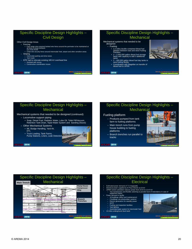
Specific Discipline Design Highlights –Mechanical
Pump HouseCompressorBldg
Main Trench
Branch Trenches
Specific Discipline Design Highlights –Electrical
• Estimated power demand of 7.5 megawatts• Electrical power supplied by El Paso Electric at 23 kV• UPRR owned substation reduces power from 23 kV to 12.47 kV
– Two transformers and flexible switching to provide level of redundancy in case of equipment failure
• Power demand in facility– 18 buildings (office and maintenance)– 2 buildings use photovoltaic systems– Electric generators for standby power– IWTP– Fueling and inspection facilities– Yard lighting– Automated gate system for Intermodal Yard
• 13 miles underground duck bank
© AREMA 2014 20

Specific Discipline Design Highlights –Architectural
• Designed 23 structures• 79,090 total square feet• Building functions:
– Office– Maintenance– Industrial– Employee welfare– Vehicle Processing/Identification
• UPRR will pursue LEED certification for buildings, anticipate Gold certification– Yard Office– Gatehouse Administrative Building
Specific Discipline Design Highlights –Architectural
Specific Discipline Design Highlights –Architectural
Specific Discipline Design Highlights –Utilities
• Designed water and sanitary system for facility– 2.4 miles of public sanitary sewer from point of
tap in to meter– 32,000 LF of sanitary sewer pipeline– 2.7 miles of public water from point of tap in to meter
61 000 LF f t i li– 61,000 LF of water pipeline• Water and sanitary sewer services provided to a majority
of the buildings• 300,000 gallon water storage tank • 4 lift stations• Septic system
Specific Discipline Design Highlights –AGS
Automated Gate System (AGS)– Automate the process of getting drivers, vehicles and cargo through
the Intermodal Facility– Fully automated system– Key componentsKey components
• Inbound and outbound truck canopies• Inbound and outbound truck portals• Drivers’ help kiosk• Gatehouse building• Gates• Loop detectors• Truck Inspection
Fun Facts
• 0.52 miles deep cut on a NFL football field
• 0.37 miles high fill on a NFL football field
• Enough fill to construct the Great Pyramid of Giza
• If soil is placed in 53’ containers and double stacked on a train, it would stretch 260 miles. That’s like driving from Santa Teresa to Albuquerque.
© AREMA 2014 21
Santa Teresa Construction
Construction was awarded with two bid packages• Bid Package 1 – mass grading, road construction, utility build in and jack
and bore casing pipes – Ragnar Benson• Bid Package 2 – everything else - Sundt
– $400 000 000 total estimated$400,000,000 total estimated construction value (UPRR and Contractor)
– Needed to get grading going as quickly as possible to meet operational deadlines
– Construction began June 2011– Fueling Facility operational January 1, 2014– Intermodal Yard operational April 1, 2014
Santa Teresa Construction Prior to Construction
Santa Teresa Construction7-28-2012
Santa Teresa Construction4-29-2014
Santa Teresa Construction –Track Liner
Santa Teresa Construction –Track Construction
© AREMA 2014 22
Santa Teresa Construction –DTL Road
Santa Teresa Construction – First Train on Shoofly Track and Main Pipe Trench
Santa Teresa Construction –Diesel Fuel Tanks and Containment
Santa Teresa Construction –2,000,000 Gallon Diesel Fuel Tank
Santa Teresa Construction –Yard Office
Santa Teresa Construction –Fueling Islands/Track Pans
© AREMA 2014 23
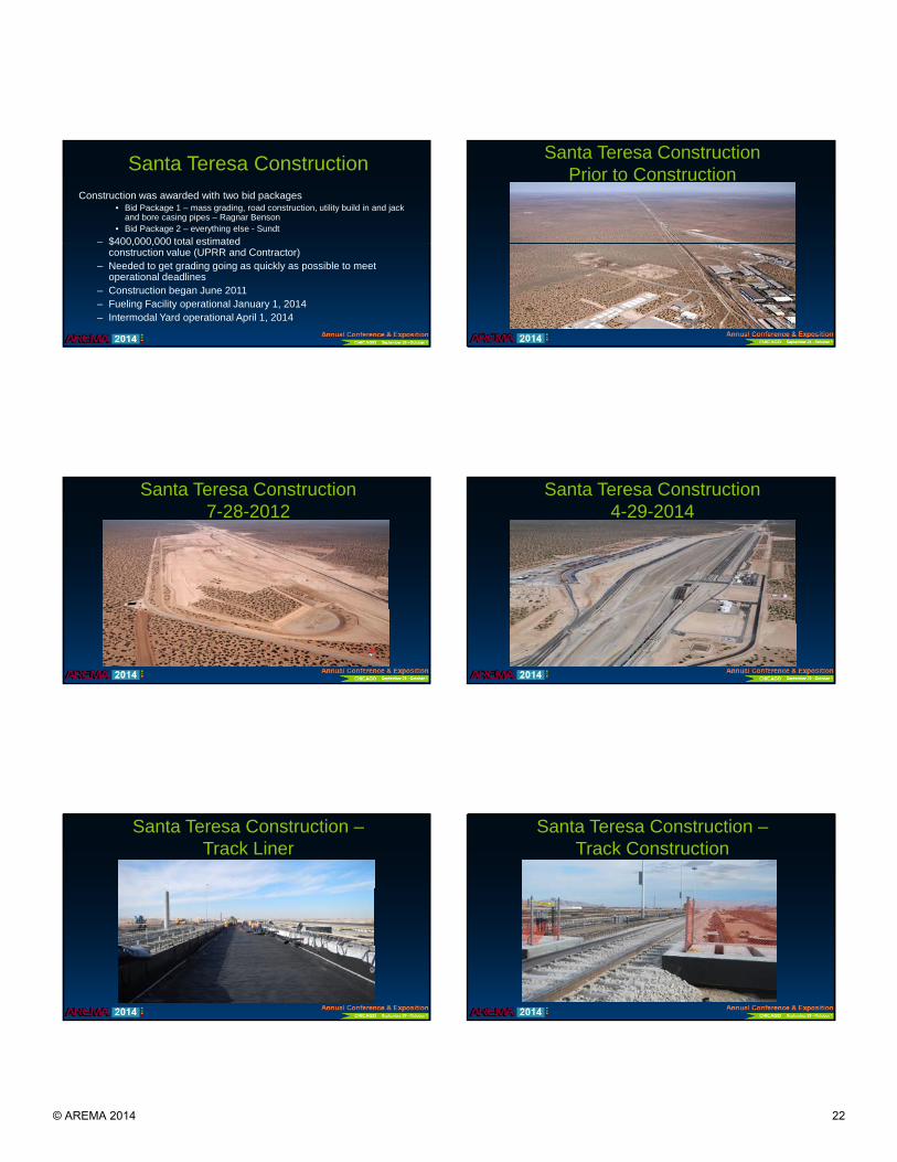
Santa Teresa Construction –Fueling Island
Radiator Water
Lube OilToilet Chemical
Water SoapDiesel Fuel
Santa Teresa Construction –Track Signals
Santa Teresa Construction –Main Pump House Bldg
Santa Teresa Construction –Product Storage Tanks West Platform
Santa Teresa Santa Teresa
Q & A
© AREMA 2014 24
Santa Teresa
Thank You!
© AREMA 2014 25