Final Report Project Name: MMAC Home Security … · Final Report 22 April 2013 Project Name: MMAC...
21
EEL 4924 Electrical Engineering Design (Senior Design) Final Report 22 April 2013 Project Name: MMAC Home Security (Formerly: In Home Security System) Team Members: Name: Adrian Cook Name: Matthew Mangan Project Abstract: Our goal is to make an in-home security system with five different types of sensors: motion (camera), motion (PIR), open/close, vibration, and carbon monoxide. Open/close sensors will be used to detect windows and doors opening and closing. Vibration sensors will be used to detect potential break- ins through windows and doors. Both kinds of motion sensors will detect movement within their range. Carbon monoxide sensors will detect harmful amounts of carbon monoxide in the house. These peripheral sensors will wirelessly send information to a central processing station that will detect where a potential intrusion or harmful levels of carbon monoxide are occurring within the house. An image sensor at the main door will also capture video of people who knock at the door, which will be sent to a server, which the owner can log into, and can then choose to remotely unlock the door and deactivate the alarm system remotely if he/she chooses. The central processing station will alert the user of any potential threats via an audio system and webpage alert system. The central processing station will also be linked to a keypad and LCD interface, so that the user can set the alarm system to different security profiles. .
-
Upload
nguyenkiet -
Category
Documents
-
view
219 -
download
0
Transcript of Final Report Project Name: MMAC Home Security … · Final Report 22 April 2013 Project Name: MMAC...

EEL 4924 Electrical Engineering Design
(Senior Design)
Final Report
22 April 2013
Project Name: MMAC Home Security
(Formerly: In Home Security System)
Team Members:
Name: Adrian Cook Name: Matthew Mangan
Project Abstract:
Our goal is to make an in-home security system with five different types of sensors: motion
(camera), motion (PIR), open/close, vibration, and carbon monoxide. Open/close sensors will be used to
detect windows and doors opening and closing. Vibration sensors will be used to detect potential break-
ins through windows and doors. Both kinds of motion sensors will detect movement within their range.
Carbon monoxide sensors will detect harmful amounts of carbon monoxide in the house. These
peripheral sensors will wirelessly send information to a central processing station that will detect where
a potential intrusion or harmful levels of carbon monoxide are occurring within the house. An image
sensor at the main door will also capture video of people who knock at the door, which will be sent to a
server, which the owner can log into, and can then choose to remotely unlock the door and deactivate the
alarm system remotely if he/she chooses. The central processing station will alert the user of any
potential threats via an audio system and webpage alert system. The central processing station will also
be linked to a keypad and LCD interface, so that the user can set the alarm system to different security
profiles.
.

University of Florida EEL 4924—Spring 2013 23-Apr-13 Electrical & Computer Engineering
Page 2/21 Final Report: In Home Security System
Table of Contents:
Introduction and Features……………………………………………………………………………… 3
Analysis of Competitive Products……………………………………………………………………... 4
Technical Objectives………………………………………………………………………………….... 5
Project Architecture……………………………………………………………………………………. 7
Flowcharts……………………………………………………………………………………………... 10
Separation of Work……………………………………………………………………………………. 12
Bill of Materials……………………………………………………………………………………….. 12
Project Schedule………………………………………………………………………………………. 16
Appendix A: Schematics……………………………………………………………………………… 17
List of Tables and Figures:
Figure 1: Block Diagram of How All Boards Communicate……………………………………..…….. 7
Figure 2: Block Diagram of Window Board………………………………………………………..…... 7
Figure 3: Block Diagram of Room Board………………………………………………………..……... 8
Figure 4: Block Diagram of Door Board…………………………………………………………..….... 8
Figure 5: Block Diagram of Central Processing Station….……………………………………..……… 9
Figure 6: Flowchart for CPS………………………………………………………………………….... 10
Figure 7: Flowchart for Door………………………………………………………………………..…. 10
Figure 8: Flowchart for Room/Window…………………………………………………………..…… 11
Figure 9: Gantt Chart……………………………………………………………………………..……. 16
Figure 10: Door Schematic Part I………………………………………………………………..…….. 17
Figure 11: Door Schematic Part II……………………………………………………………..……… 17
Figure 12: Door Schematic Part III…………………………………………………….…….……….. 18
Figure 13: Door Schematic Part IV………………………………………………………….………... 18
Figure 14: Door Schematic Part V………………………………………………………….…………. 19
Figure 15: CPS Schematic Part I……………………………………………………………………… 19
Figure 16: CPS Schematic Part II……………………………………………………………………... 20
Figure 17: CPS Schematic Part III………………………………………………………...………….. 20
Figure 18: Room Schematic………………………………………………………………..…………. 21
Figure 19: Window Schematic………………………………………………………………………... 21
Table 1: Responsibility Table for Different Project Aspects………………………………………… 12
Table 2: Bill of Materials for Window Board…………………………………………………….….. 12
Table 3: Bill of Materials for Room Board…………………………………………………………... 13
Table 4: Bill of Materials for Door Board……………………………………………………………. 14
Table 5: Bill of Materials for Central Processing Station…………………………………………….. 15
Table 6: Cost Breakdown by Board Type……………………………………………………………. 16

University of Florida EEL 4924—Spring 2013 23-Apr-13 Electrical & Computer Engineering
Page 3/21 Final Report: In Home Security System
Introduction and Features:
Commercial in home security systems typically offer a wide range of services. The most general
features include:
Break-In Detection – Recognition of attempted forceful entry into the house, most commonly
through doors and windows
Motion Detection – Detection of intrusion within the home
Carbon Monoxide Detection – Recognition of harmful levels of carbon monoxide gas within
the house
System Log – Keep a permanent system log of everything that has occurred since system
activated
Different Security Profiles – Ability to turn off alerts from various sensors based upon whether
the user is within the house or outside the house
Sound Alert System – Alerting the resident of any unsafe detection
Our security system incorporates these key components in a completely in house system. In
addition, our security system differentiates itself from traditional competitors by offering the following
features:
User Installable – Ability for a user to configure the security system themselves for their home
Scalable- Sensors automatically add themselves to the system, and send standardized codes, so
it is easily scalable
Video Stream– Video of people knocking at the main door can be captured and sent to the
website for resident’s review
Remote Control – Full control of the security system via webpage
Home Automation – Automatic doorbell when knock detected, and ability to unlock your front
door via webpage
No Corporate Monitoring – All processing, alerts, etc. is done in house without a remote
connection to some company server. Thus, privacy is fully preserved.
By creating a user-installable security system, our system is more cost efficient than traditional
commercial systems. Labor fees for installation of the security system often accounts for a sizeable
amount of the total cost. By keeping all the processing in-house too, no remote servers are needed to
monitor the system. Thus, users can be assured that their privacy is not being invaded whatsoever.

University of Florida EEL 4924—Spring 2013 23-Apr-13 Electrical & Computer Engineering
Page 4/21 Final Report: In Home Security System
Analysis of Competitive Products:
Three examples of popular in-home security systems are shown below:
GE Security System: $19.99/month
Free equipment
GE Simon XT Control Panel
3 Door/Window Sensors (Open/Close sensors)
1 motion detector
Wireless sensors
Vivint Home Security: $49.99/month, $99 activation fee
Touchscreen Panel
Window/door Sensors
Smoke detector
CO sensor
Glass break detector
Motion detector
Key fob
Remote Monitoring
Wireless sensors
ADT: Total Installation: $35.99/month, $349.00 installation fee
1 Monitored Security System
2 Door/Window Sensors (open/close sensors)
1 Motion Detector
1 Indoor Sounder
Wireless Sensors
It can be seen that our system matches the capabilities of all these systems and even goes beyond
them. Our system incorporates home-automation features and also gives you, personally, remote-
monitoring capabilities. In addition, none of these systems include video streams for you to see what is
going on outside your home like our system does. In addition to giving more features, we beat all three
of these systems in cost. Our system has a one-time cost to buy all the sensors and no installation fee,
whereas all of these systems charge you a monthly fee so that others can remotely monitor the system.
References:
http://www.protectamerica.com/ge-simon-security-systems/wireless-home-alarm/copper-package
http://www.adt.com/media/home-
security?ecid=rfresips000106&se=google&media=general&gclid=CO7Mjdnv3rYCFQVV4Aod6EkAS
A
http://www.vivint.com/en/ppc/security?exid=20203&gclid=CM-ZnePv3rYCFYHe4Aod6zoATQ

University of Florida EEL 4924—Spring 2013 23-Apr-13 Electrical & Computer Engineering
Page 5/21 Final Report: In Home Security System
Technical Objectives:
Analog Design
The motion and vibration sensors are designed using analog circuitry to guarantee quick
response to intrusions, since those will likely be the greatest security threat. They are powered via
batteries for approximately a month and are discrete in size. The vibration sensor requires a piezo
electric material on the window or door to detect when someone is trying to break in or knock, which
will have to be filtered for noise, amplified, and compared with a threshold signal to guard against false
alarms. The motion sensor requires a magnetic field, and a reed switch, which will be affected by the
magnetic field. When the window is open the switch will no longer be affected by the magnetic field and
will trigger the alarm. Additionally, the motion sensor for the room uses a passive infrared (PIR) sensor.
This sensor has two different cells of photosensitive diodes tuned to the IR energy band, and these will
be compared looking for a difference in order to determine if there is movement. The signals from the
PIR sensor will have to be filtered, amplified, differenced together, and compared to a voltage threshold
to see if movement has occurred.
Some other analog design considerations had to be taken into account as well. For example, the
door board has an inrush current of about 1 amp. Hence, large capacitors were required on the voltage
line so that the voltage would not dip below the brown out level of any of the devices, because the
camera, microprocessor, and Xbees are sensitive to this. Also, on the central processing station, when
the speaker is sounding more than 1 amp of current was being drawn, so the power source had to be able
to supply 18V at 1 amp while still giving a steady 3.3V and 5V rails to the microprocessor and LCD
respectively.
Finally, on the door board, in order to open the door remotely, the microprocessor operating at
3.3V had to switch the 12V rail to the solenoid in order to throw it. In order to do this a logic level
NMOS is used. The microprocessor drives the gate high to keep the NMOS “closed” giving the solenoid
a steady 12V and keeping it in the locked position. When the door needs to be open, the microprocessor
drives the gate low. The switch is now open, so the solenoid no longer receives 12V, and unlocks. To
prevent damage from inductive feedback, a schottky diode is placed across the solenoid.
Wireless Communication
Wireless communication will be done using XBee in a point-to-multipoint network, so that all
peripheral sensors can communicate with the central processing station. XBees will have to be
configured so that they can all seamlessly communicate to the central processing station without major
hold ups in the process. Also, the central processing station will need to be able to transmit to the Xbee
on the door to open the electronic deadbolt. Addionally, an Xbee Wifi module will be used to
communicate with the server. The baud rate on this Xbee will have to be very high since it is being used
to stream video.
Central Processing Station (CPS)
The central processing station is in charge of keeping track of active sensors based upon the
security profile that is in use. The central processing station is powered via a wall outlet. The software
running on the central processing station is designed so that a user can setup the security system
themselves (i.e. number of room sensors, door sensors, etc. in the house). The central processing station
will be the main place of user interaction with a keypad and LCD as well as relay the correct codes to

University of Florida EEL 4924—Spring 2013 23-Apr-13 Electrical & Computer Engineering
Page 6/21 Final Report: In Home Security System
the server so that the server can also be updated. The CPS is a completely interrupt driven system,
except for the user interface of the keypad and LCD. The CPS uses USART receive interrupt to get the
alerts from the peripheral sensors and servers, update the status, send codes to the server, sound the
alarm, etc. The CPS uses all 4 timers on the Atmega1284P. Timer0 is used to time the system arming
and give the user 30 seconds to vacate the premises before sensors are active. Timer1 is used to make
sure no sensor can flood the system, by blocking the same code from the same sensor for 30 seconds.
Timers 2 and 3 are used in order to control notes being played on the speaker (SPI) and the length of
each of those notes.
Microprocessor interface with OV7670 and Image Processing
An ARM Cortex M4 from STMicroelectronics (STM32F407) was used to interface to an
OV7670 CMOS VGA camera module on the door board. The M4 interfaces with the OV7670 through
its Digital Camera Interface (DCMI). The DCMI and Direct Memory Access Controller (DMA) on the
M4 make capturing frames without CPU intervention possible, so the M4 is free to monitor its other
sensors and pass along messages from the CPS to the Server (and vice versa). This is paramount because
a missed alert in a security system is unacceptable. By feeding the OV7670 a 29 MHz clock, the M4 is
able to capture approximately 25 frames per second. When not streaming these frames to the server, the
M4 performs a frame differencing algorithm with an averaging filter for motion detection. It compares
new frames to a background frame it has composed, and sends a message back to the CPS if it detects
that the new frame has something in it that isn’t a part of the background image.
Server
A java server was set up using Google App Engine and serves as the remote access point for the
system. The server opens a secure socket to the Xbee Wifi on the door sensor. This socket is used to
communicate between the server and the rest of the security system so that the server can be updated and
give commands. The server has a webpage called: www.mmachomesecurity.com. From this webpage
any family member can view the latest status update from the system, remotely control the system using
the password they configured on the CPS, or post on the message board. Additionally, they can view the
full system log, the current system configuration, and switch the camera from motion to a video stream
in order to see what is happening at their front door.

University of Florida EEL 4924—Spring 2013 23-Apr-13 Electrical & Computer Engineering
Page 7/21 Final Report: In Home Security System
Project Architecture:
High Level Overview
Figure 1: Block Diagram of How All Boards Communicate
Our system is comprised of four different types of boards and a server. The Central Processing
Station receives alerts from room, window, and door boards, and then relays that information back to the
server using the door as a middle man. The server keeps a log of all the events that occur in the security
system, such as adding new sensors, setting off sensors, etc. All systems communicate with each other
wirelessly, and have their own unique ID, so that when the CPS and Server receive an alert, they know
exactly what sensor was set off and which location it came from. In addition, the server can also send
commands back to the central processing station through the door for remote command functionality via
a website interface.
Windows
Figure 2: Block Diagram of Window Board
Window board feature both vibration and motion analog sensors to detect break-ins and
openings. Whenever a sensor is set off, the window sensor sends an alert back to the CPS. These boards
are battery operated and are equipped with power saving software features.
Motion Sensor
Vibration Sensor
Xbee Wireless Module
ATTiny24a
Room
Window
Door
Server
Central Processing
Station

University of Florida EEL 4924—Spring 2013 23-Apr-13 Electrical & Computer Engineering
Page 8/21 Final Report: In Home Security System
Rooms
Figure 3: Block Diagram of Room Board
Room boards feature analog motion and CO sensors to detect motion within a room and harmful
levels of carbon monoxide in the air. Whenever a sensor is set off, the room sensor will send an alert
back to the CPS. These boards are battery operated and feature power saving software features.
Doors
Figure 4: Block Diagram of Door Board
Motion Sensor
CO Sensor
Xbee Wireless Module
ATTiny24a
Camera
Electric Deadbolt
ARM Cortex M4
Motion Sensor
Multi-Level Vibration
Sensor
XBee WiFi module
XBee RF module
University of Florida EEL 4924—Spring 2013 23-Apr-13 Electrical & Computer Engineering
Page 9/21 Final Report: In Home Security System
The Door board features a multi-level vibration sensor and two different motion sensors. The
multi-level vibration sensor can differentiate between knocks and break-ins. The analog motion sensor is
a reed switch that detects when the door is open or closed. The digital motion sensor is the OV7670
camera module which the ARM Cortex M4 captures frames from and performs image processing to
detect when something is moving within the frame. The Door sensor sends alerts back to the Central
Processing Station, relays messages from the Central Processing Station to the server, and vice versa. It
can also receive direct commands from the server to startup a live video feed on the website.
Central Processing Station
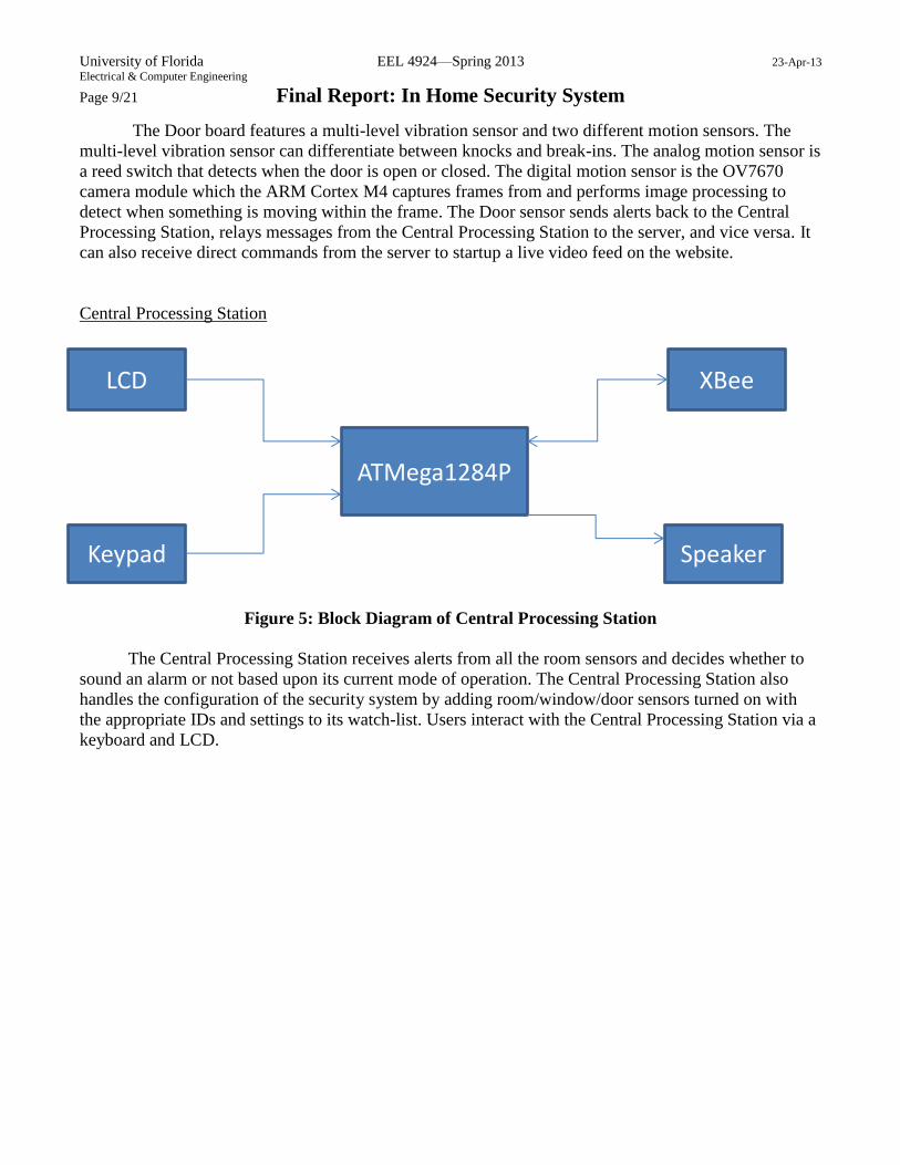
Figure 5: Block Diagram of Central Processing Station
The Central Processing Station receives alerts from all the room sensors and decides whether to
sound an alarm or not based upon its current mode of operation. The Central Processing Station also
handles the configuration of the security system by adding room/window/door sensors turned on with
the appropriate IDs and settings to its watch-list. Users interact with the Central Processing Station via a
keyboard and LCD.
LCD
Keypad
XBee
Speaker
ATMega1284P

University of Florida EEL 4924—Spring 2013 23-Apr-13 Electrical & Computer Engineering
Page 10/21 Final Report: In Home Security System
Flowcharts:
Figure 6: Flowchart for CPS
Figure 7: Flowchart for Door

University of Florida EEL 4924—Spring 2013 23-Apr-13 Electrical & Computer Engineering
Page 11/21 Final Report: In Home Security System
Figure 8: Flowchart for Room/Window

University of Florida EEL 4924—Spring 2013 23-Apr-13 Electrical & Computer Engineering
Page 12/21 Final Report: In Home Security System
Separation of Work:
Adrian Cook Matthew Mangan
Preliminary Research 50 50
Part Ordering 30 70
Power Design 35 65
Analog Design 65 35
Wireless Communication 40 60
Camera Interfacing 10 90
Motion Detection with Camera
0 100
Door Hardware/Software Design
5 95
Window Hardware/Software Design
95 5
Room Hardware/Software Design
95 5
CPS Software Design 90 10
CPS Hardware Design 25 75
Server Software 100 0
Test and Debug 50 50
Physical Assembly 50 50
Table 1: Responsibility Table for Different Project Aspects
Bill of Materials:
Window
Item Description Quantity Cost
ATTiny24A 1 $1.12
Xbee Series 1 802.15.4 1 $22.95
Reed Switch 1 $0.62
PiezoElectric Transducer 1 $3.99
SPST Switch 2 $1.96
LM393 Comparator 1 $0.55
LT1632 Op Amp 1 $6.66
15KΩ, 1/4 Watt Resistor 1 $0.15
8KΩ, 1/4 Watt Resistor 1 $0.11
7KΩ, 1/4 Watt Resistor 1 $0.12
1KΩ, 1/4 Watt Resistor 5 $0.55
1uF 25V Capacitor 1 $0.34
.1uF 25V Capacitor 1 $0.29
Total $39.41
Table 2: Bill of Materials for Window Board
University of Florida EEL 4924—Spring 2013 23-Apr-13 Electrical & Computer Engineering
Page 13/21 Final Report: In Home Security System
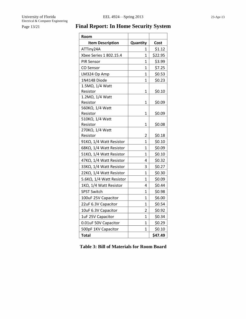
Room
Item Description Quantity Cost
ATTiny24A 1 $1.12
Xbee Series 1 802.15.4 1 $22.95
PIR Sensor 1 $3.99
CO Sensor 1 $7.25
LM324 Op Amp 1 $0.53
1N4148 Diode 1 $0.23
1.5MΩ, 1/4 Watt Resistor 1 $0.10
1.2MΩ, 1/4 Watt Resistor 1 $0.09
560KΩ, 1/4 Watt Resistor 1 $0.09
510KΩ, 1/4 Watt Resistor 1 $0.08
270KΩ, 1/4 Watt Resistor 2 $0.18
91KΩ, 1/4 Watt Resistor 1 $0.10
68KΩ, 1/4 Watt Resistor 1 $0.09
51KΩ, 1/4 Watt Resistor 1 $0.10
47KΩ, 1/4 Watt Resistor 4 $0.32
33KΩ, 1/4 Watt Resistor 3 $0.27
22KΩ, 1/4 Watt Resistor 1 $0.30
5.6KΩ, 1/4 Watt Resistor 1 $0.09
1KΩ, 1/4 Watt Resistor 4 $0.44
SPST Switch 1 $0.98
100uF 25V Capacitor 1 $6.00
22uF 6.3V Capacitor 1 $0.54
10uF 6.3V Capacitor 2 $0.92
1uF 25V Capacitor 1 $0.34
0.01uF 50V Capacitor 1 $0.29
500pF 1KV Capacitor 1 $0.10
Total $47.49
Table 3: Bill of Materials for Room Board

University of Florida EEL 4924—Spring 2013 23-Apr-13 Electrical & Computer Engineering
Page 14/21 Final Report: In Home Security System
Door
Item Description Quantity Cost
STM32F407ZET6 1 $11.71
Xbee Series 1 802.15.4 1 $22.95
Xbee WiFi 2.4GHz b/g/n 1 $35.00
OV7670 VGA CMOS Camera 1 $18.00
LM393 Comparator 1 $0.55
LT1632 Op Amp 1 $6.66
Deadbolt (solenoid) 1 $18.00
Reed Switch 1 $0.62
PiezoElectric Transducer 1 $3.99
12V 6A Power Supply 1 $13.00
68KΩ, ¼ Watt Resistor 1 $0.09
15KΩ, ¼ Watt Resistor 2 $0.30
10KΩ, ¼ Watt Resistor 4 $0.44
8.2KΩ, ¼ Watt Resistor 1 $0.10
5.6KΩ, ¼ Watt Resistor 1 $0.09
3.3KΩ, ¼ Watt Resistor 1 $0.08
1KΩ, ¼ Watt Resistor 10 $1.10
680uF 35V Capacitor 1 $3.53
4.7uF 6.3V Capacitor 1 $0.86
2.2uF 10V Capacitor 2 $1.26
1uF 16V Capacitor 3 $0.93
.1uF 25V Capacitor 15 $4.35
45V 15A Schottky Diode 1 $0.99
60V 30A N-Channel MOSFET 1 $0.95
L5973D Switching Reg 1 $3.28
330uF 6.3V Capacitor 1 $2.20
220pF 50V Capacitor 1 $0.24
22nF 50V Capacitor 1 $0.24
25V 2A Schottky Diode 1 $0.77
15uH Power Inductor 1 $0.34
10uF 35V Capacitor 1 $2.34
Coaxial DC Jack 1 $0.84
Total $155.80
Table 4: Bill of Materials for Door Board

University of Florida EEL 4924—Spring 2013 23-Apr-13 Electrical & Computer Engineering
Page 15/21 Final Report: In Home Security System
Central Processing Station
Item Description Quantity Cost
ATMega1284P 1 $8.13
Xbee Series 1 802.15.4 1 $22.95
LTC1661 DAC 1 $3.39
LT1632 Op Amp 1 $6.66
LCD 20x4 Characters 1 $17.95
Linear 10K Potientiometer 2 $1.98
Keypad 4x4 1 $3.95
LM1875 Power Amp 1 $2.80
Coaxial DC Jack 1 $0.84
20V 70W Power Supply 1 $18.00
20W 8Ω Speaker 1 $10.98
2KΩ, ¼ Watt Resistor 4 $0.32
3.3KΩ, ¼ Watt Resistor 2 $0.16
5.6KΩ, ¼ Watt Resistor 1 $0.09
10KΩ, ¼ Watt Resistor 4 $0.44
22KΩ, ¼ Watt Resistor 3 $0.30
200KΩ, ¼ Watt Resistor 1 $0.09
1MΩ, ¼ Watt Resistor 1 $0.08
1Ω, 1 Watt Resistor 1 $0.33
1000uF 35V Capacitor 2 $7.18
220uF 35V Capacitor 1 $3.63
100uF 25V Capacitor 1 $6.00
10uF 25V Capacitor 2 $1.34
1uF 25V Capacitor 1 $0.34
0.22uF 25V Capacitor 1 $0.34
0.1uF 25V Capacitor 1 $0.29
L5973D Switching Reg 2 $6.56
330uF 6.3V Capacitor 2 $4.40
220pF 50V Capacitor 2 $0.48
22nF 50V Capacitor 2 $0.48
25V 2A Schottky Diode 2 $1.44
15uH Power Inductor 2 $0.68
10uF 35V Capacitor 2 $4.68
1N914 Diode 2 $0.20
Total $137.48
Table 5: Bill of Materials for Central Processing Station

University of Florida EEL 4924—Spring 2013 23-Apr-13 Electrical & Computer Engineering
Page 16/21 Final Report: In Home Security System
Board Cost
Window $39.41
Room $47.49
Door $155.80
Central Processing Station $137.48
Total $380.18
Table 6: Cost Breakdown by Board Type
Project Schedule:
Figure 9: Gantt Chart

University of Florida EEL 4924—Spring 2013 23-Apr-13 Electrical & Computer Engineering
Page 17/21 Final Report: In Home Security System
Appendix A: Schematics
Door
Figure 10: Door Schematic Part I
Figure 11: Door Schematic Part II

University of Florida EEL 4924—Spring 2013 23-Apr-13 Electrical & Computer Engineering
Page 18/21 Final Report: In Home Security System
Figure 12: Door Schematic Part III
Figure 13: Door Schematic Part IV

University of Florida EEL 4924—Spring 2013 23-Apr-13 Electrical & Computer Engineering
Page 19/21 Final Report: In Home Security System
Figure 14: Door Schematic Part V
Central Processing Station
Figure 15: CPS Schematic Part I

University of Florida EEL 4924—Spring 2013 23-Apr-13 Electrical & Computer Engineering
Page 20/21 Final Report: In Home Security System
Figure 16: CPS Schematic Part II
Figure 17: CPS Schematic Part III

University of Florida EEL 4924—Spring 2013 23-Apr-13 Electrical & Computer Engineering
Page 21/21 Final Report: In Home Security System
Rooms:
Figure 18: Room Schematic
Window
Figure 19: Window Schematic