![Muscle stretching in manual therapy i the extremities[team nanban][tpb]](https://static.fdocuments.net/doc/165x107/568caa0b1a28ab186d9ff4ef/muscle-stretching-in-manual-therapy-i-the-extremitiesteam-nanbantpb-5705e5d62eedf.jpg)
Muscle stretching in manual therapy i the extremities[team nanban][tpb]

Final Report
Muscle Recorder
Team 1
Team members: Roua Taha, Mark Mazmanian, Angela Correa
Client Contact: Dr. John D. Enderle
Program Director and Professor University of Connecticut
A.B. Bronwell Building, Room 217 260 Glenbrook Road, Unit 2247
Storrs, CT 06269-2247 Phone: (860) 486-5838 Fax: (860) 486-2500
Email: [email protected]: www.engr.uconn.edu/~jenderle/

Table of Contents Abstract......................................................................................................................3 1 Introduction.............................................................................................................4 1.1Background.................................................................................................4 1.2 Purpose of the Project................................................................................4 1.3 Previous Work Done by Others..................................................................4 1.3.1 Products……………………………………………………………………….5 1.3.2 Patents……………………………………………………………………..….5 1.4 Map of Final Report....................................................................................6 2 Project Design.........................................................................................................8 2.1 Design Alternatives....................................................................................8 2.1.1 Design 1…………………………………………………………………........8 2.1.2 Design 2……………………………………………………………………...13 2.1.3 Design 3……………………………………………………………………...16 2.2 Optimal Design.........................................................................................19 2.2.1 Objectives……………………………………………………………….......19 2.2.2. Subunits……………………………………………………………………..22 3 Realistic Constraints............................................................................................53 4 Safety Issues.........................................................................................................55 5 Impact of Engineering Solutions.........................................................................56 6 Life-Long Learning...............................................................................................58 7 Budget and Timeline............................................................................................59 7.1 Budget......................................................................................................59 7.2 Timeline....................................................................................................61 8 Team Member Contributions...............................................................................62 9 Conclusion............................................................................................................63 10 References..........................................................................................................64 11 Acknowledgements............................................................................................64 12 Appendix.............................................................................................................65 12.1 Updated Specifications..........................................................................65
2
Abstract:
The Biomedical Engineering (BME) Department of the University of Connecticut has requested a device called the “Muscle Recorder” in order to be used in the program’s BME Measurements course. The device will allow the students to understand the mechanics of muscle contraction by recording the Force-Velocity relationship as well as the Length-Tension relationship for a variety of muscles at different stimuli percentages. The Force-Velocity relationship should be able to record both the muscle’s lengthening (concentric contraction) as well as the shortening (eccentric contraction). Muscle Mechanics is the study of the energy and forces involved in muscle movements. Most devices used in other laboratories measure only the shortening of the muscle, but this device will also be able to measure the lengthening of the muscle. The sponsor for our project Dr. Enderle, requested the building of this device as an incentive to encourage and promote BME students in the laboratory to improve their knowledge in the subject in conjunction with a computer software that will greatly help with the set up, recording and output of the experiment, as well as the fact that students will be more exposed to this useful software.
The entire device will consist of a plastic enclosure or casing consisting of
a lever being attached to a motorized track by means of a fulcrum. The muscle will be attached to the lever by a clamp; a tray that will hold the weights is attached to the lever as well. On the opposite side of the enclosure, there is the Hall Effect system, a magnetic sensor plate, a force transducer, and a PCB board. The bottom contains a saline reservoir, a pump and a vinyl tube pipe that sprays the muscle specimen with saline solution. With the help of National Instruments (NI) and the LabVIEW® software working together, the muscle will be stimulator through a pair of electrodes attached to the muscle, and the graphs showing the Force-Velocity (for both shortening and lengthening) and Length-Tension Relationships would be acquired and displayed after several trials for the experiment. This device will be enclosed in order to keep it safe from the medium and it is a good way to carry the entire set up in case it needs to be moved around.
The muscle recorder is unique in the sense that the LabVIEW® software
will control be providing the stimulation to the muscle instead of having an actual muscle stimulator, it will be timing the saline solution and as stated before, it will also display the Force-Velocity for the lengthening of the muscle as well. This project needs to be analyzed and several factors were taking into consideration before actual agreement on various parts of the building. Safety and environmental constraints are considered since this device uses an animal muscle in order to satisfy the requirements.
3

1. Introduction: 1.1 Background:
Dr. John D. Enderle is the Program Director & Professor for Biomedical Engineering at the University of Connecticut. He has been looking to incorporate a muscle response experiment in the Biomeasurements laboratory, a class designed for Biomedical Engineering undergraduates. Currently, undergraduate students in the Biomedical Engineering program perform experiments on frog muscles in the Physiology and Neurobiology class required by the program. Dr. Enderle would like to include a muscle experiment in the Biomeasurements Laboratory to ensure that the undergraduate students gain a deeper understanding of muscle performance by analyzing muscle responses using a LabVIEW® program. 1.2: Purpose of the project:
The University of Connecticut’s BME Dept. has requested a muscle recorder for use in the program’s Biomedical Engineering Measurements course. The device will allow the students to understand the mechanics of muscle contraction by recording the force-velocity and length-tension relationships for a variety of muscles. Moreover, the students will learn how the LabVIEW® program operates in conjunction with the experiment in order to gain as much knowledge and practice in the course. There are some basic requirements that the mucscle recorder should adhere to. The primary requirement for the device is to record the length-tension and force-velocity relationships for a variety of muscles. The muscle recorder should measure the tension and length of the muscle at various stimulation levels. The peak velocity will also be measured at different stimulation levels in addition to different loads for both shortening and lengthening of the muscles. A program should be written using the LabVIEW software in order to automate the recorder and display information from the data.The muscles primarily used will be skeletal muscles ranging from 5mm to 25cm in length.The device must be user friendly, portable, durable and safe; it should also be able to withstand load.
1.3 Previous Work Done by Others
There are some products that stimulate muscles for different reasons. Some are used in laboratories in animal muscle in order to study reactions and cures, and some others are used in hospitals in order to help people that suffer from some disorders by stimulating some parts of muscles. No product was found that could be producing the same type of results that are being studied for with our muscle recorder. Neither seem any of these products to use the LabView® software to either stimulate the muscle or provide the relationships of the desired measurements.
4

1.3.1 Products ELECTRONIC MUSCLE/NEUROMUSCULAR STIMULATORS: The Electronic Muscle/Neuromuscular Stimulators are used in diagnosis, evaluation and treatment of muscle dysfunction caused by peripheral and C.N.S. (Central Nervous System) disorder. They are also used for preventing or retarding disuse atropy, relaxing muscle spasms and muscle re-education. The stimulators features user replaceable electrodes and wires either water soaked or conductive rubber electrodes. Additional features include ring current adjustment, active probe positioning, on-off control and easy operation with hemiplegics. The unit may be operated with one hand. It weights 8 ounces, and it is available to physicians and registered physical therapists only. [1]. HIGH VOLTAGE ELECTRONIC GALVANIC STIMULATOR (MODEL EGS100-2S): The High Voltage Electronic Galvanic Stimulator, model EGS100-2S, generates pulses from 1 to 120 per second at voltage from 0 to 500 volts to stimulate nerves, joints, and muscles in water. Features include 2 active, moistened 2 x 2 inch or 4 x 4 inch pads and one 8 x 10 inch dispersive pad, hand applicator attachment, pulse rate and voltage intensity controls. POWER: Plug in AC current. Available in 220 volts, 50 or 60 cycles for foreign countries. DIMENSIONS: 16.75 x 11 3/8 x 8 5/8 inches. WEIGHT: 15.5 pounds. Manufacturer states this product is Underwriters' Laboratory (UL) and CSA listed. This device is restricted to sale by or on the order of a licensed physician or other practitioner by the law of the state in which the practitioner practices to use or order the use of the device. [2] 1.3.2 Patent Search Results Searching in a patent database we found no results for the term “muscle recorder”, so we decided to search under “muscle stimulation” and “electrical muscle stimulation” in http://patents.cos.com/cgi-bin/result and www.uspto.gov/patft/index.html. and found a couple patents that we thought were related to our device.
U.S Patent 4,595,010 by Radke, et al. An electrical muscle stimulator that simultaneously supplies a pulse (i.e., 270, 271) to each electrode (5, 6) having first and second phases (272, 273; 274, 275) which are a mirror image to the pulse supplied to the other electrode. A control is connected to unbalance either or both the width and amplitude of the first and second phases of each pulse to selectively provide an unbalanced stimulation to one or more muscles through the electrodes (5, 6). The stimulator provides a precise control which is readily adjustable for a large number of operating sequences.
U.S Patent 06865423 by Oldham, et al. An electrical muscle stimulation that relies upon the application to the muscles of a patient of a stimulating signal which comprises a series of regularly spaced bursts of pulses. Each burst
5
includes a first component as a first continuous train of regularly spaced pulses and a second component as a series of regularly spaced second trains of regularly spaced pulses. The second component is combined with the first component and the spacing between successive pulses in the second pulse trains is less than the spacing between successive pulses in the first pulse train. A third component as a series of regularly spaced third trains of regularly spaced pulses may be combined with the first and second components, the spacing between successive pulses in the third pulse train being less than the spacing between successive pulses in the second pulse trains.
U.S Patent 20050096711 by Adib, et al. A muscle stimulator that uses methods and apparatus for stimulating the masticatory, shoulder, or back, and facial muscles. This is achieved by way of placing four output electrodes and at least one common electrode in the vicinity of the head, neck, and shoulder or back of a subject. In particular, two output electrodes are placed adjacent to the ears of the subject and two output electrodes are placed along the upper back of the subject. The at least one common transmitting electrode is placed on the back of the neck of the subject, generally just below the hairline. Stimulation of muscles/nerves in the vicinity of each output electrode is achieved substantially simultaneously by way of the current produced by the output electrodes.
U.S Patent 20070032750 by Oster, et al. A Muscle Strength Assessment System that determines patient's muscle strength of a lever arm comprising a leg, ankle, and foot. A value indicative of the strength is determined based on at least one eccentric and concentric pressure values associated with the lever arm, as well as at least one weight based. The values may be entered remotely or locally to a computer that outputs the value indicative of the strength.
U.S Patent 20060105357 by Benesch, et al. Tissue Sensor. Described are assemblies for screening a compound for bioactivity, the assemblies comprising a tissue and a sensor. A change in a biological parameter is measured by the sensor, such that a change in a parameter occurring when the tissue is contacted with a candidate compound is detected by the sensor. Assemblies provided herein include single sensor/tissue assemblies and arrays of such assemblies, including plates comprising tissues in combination with one or more sensors. Also provided are methods of screening a compound using tissue/sensor tissue assemblies as described.
1.4: Map for the rest of the report:
In the remainder of the report, we will outline the first three design alternatives and then discuss the optimal design and demonstrate its superiority compared to the previous alternatives. In the project design, an explanation for selecting the optimal design is included based on specifications and the realistic constraints for this specific device. The realistic constraints, covering economic,
6

environmental, ethical, health and safety, manufacturability, and sustainability issues, will then be discussed. The constraints will then be followed by the safety issues, the impact of engineering solutions, and a description of life-long learning. The budget will then be covered, along with a project time line. The contributions of each team member will be mentioned. A conclusion of the final project will be given; moreover, references and acknowledgements are mentioned. An appendix may be included.
7

2. Project Design: In this section, we will first describe the design alternatives and discuss their key features and their weak points. Then, we will explain our optimal design in great detail as we elaborate on the subunits. We will include diagrams of the previous and optimal design. We will demonstrate that the optimal design is superior to the three alternatives, which served as stepping stones toward a more complete design. The alternatives are not very applicable for a number of reasons. We were still learning about the design process, and we overlooked a few key concerns regarding the designs. We choose the optimal design based on several concerns including, but not limited to, its safety of use, and best possible performance. The optimal design is safer since it is made of plastic, as opposed to metal, and it is an enclosure, as opposed to the arm and stand setup of previous designs. The saline solution will be contained in the enclosure, and electrical wires are not exposed. Moreover, the muscle recorder will perform its intended function, since it is directly connected to, and automated by, LabVIEW, and it includes all the necessary subunits such as the Hall Effect system, lever, and stimulator. The optimal design meets the required specifications. 2.1 Design Alternatives: 2.1.1 Design One: The first design suggested was a stepping stone in the progress of this group from a mediocre product idea to an innovative product design. Upon retrospect, this design was rather primitive, and did not offer much improvement
8
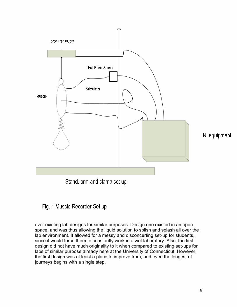
over existing lab designs for similar purposes. Design one existed in an open space, and was thus allowing the liquid solution to splish and splash all over the lab environment. It allowed for a messy and disconcerting set-up for students, since it would force them to constantly work in a wet laboratory. Also, the first design did not have much originality to it when compared to existing set-ups for labs of similar purpose already here at the University of Connecticut. However, the first design was at least a place to improve from, and even the longest of journeys begins with a single step.
9

Design one had the Hall Effect sensor lofted in the air, connected by wire to the muscle and the National Instruments box. Later it would be determined this is most likely not the best placement for the sensor, and its orientation would be altered. Furthermore, there were two electrodes connected directly from the National Instruments equipment to the muscle, which were created to apply stimulation for contraction. The muscle was connected by hook to the stand set-up, and the free loading weight was connected by string to the muscle. Also, the stand, arm, and clamp set up was assembled completely out of steel. Furthermore, this part of the project was clearly poorly developed since the steel was not even required to be painted, thus making it completely vulnerable to rust and decay even thought it was expected to be used in a moist environment. Additionally it was thought that a metal stand was necessary to be used, because of the attractive attributes steel alloys possess. Steel is a sturdy item, in the sense that with the amount of mass and weights being added to it as loads, it would not deform. Also, steel can be made relatively cheaply and is available from a wide range of companies. Since it met constraints with what it was responsible for and agreed reasonably with budget, it was thought as the best approach to making the device. Upon further review, steel’s major fallibility of not being water-resistant deemed it inappropriate for use during this project. The way that design one was set up to record length measurements was far from perfect. Accurate determination of length-tension relationships and force-velocity relationships is unattainable unless the measuring of the unknown terms can be found to a meaningful number of significant digits. The method for determining force developed in design one for the muscle was a logical one. A force transducer was to be hooked up to the top of the muscle which would then report back to the computer how much force was being generated by the muscle in contraction. This number could then be recorded for the student and applied to a graph. What was insufficient was the method described for determining the quantitative length value for the muscle in contraction. Frequently, the muscle in question will be about the size of 25 millimeters, and thus a meaningful number of significant digits would be two, with a tolerance of plus or minus half a millimeter. The method suggesting for evaluating length was to have a ruler next to the muscle which would then allow the user to read off what distance the muscle covers at that moment. There are multiple flaws in this idea, chiefly, this overlooks the fact that the muscle’s length will be changing constantly! From the instant that a muscle length is observed compared to the time its value is recorded, it will have a different length. This also would make the readings of the force transducer not match the time when the readings for the length to be taken. In order for a meaningful graph to be generated, the moments when the values of length tension were recorded would have to match exactly. Also, there is no incorporation of a place to keep the ruler still since it would have to be in order to generate its most accurate possible reading. There should have been a holster for the ruler so that it would not be jittering or shaking in the palm of the operator, keeping the position of the ruler at rest. A ruler’s measurements would do no
10
good if its original position kept changing. Furthermore, all these potential improvements on the ruler’s recordings are moot anyway since a ruler is too inaccurate a device for use on this project. The accuracy of the length measurement must give two reliable significant figures in order to be valid for the purpose of this experiment. A human reading the millimeter value off a cheap ruler would only give a value accurate to plus or minus 3 millimeters if the user does a good job of keeping it steady. The graduates for millimeters are very close together and difficult to read in a pressured environment where the user would be trying to keep up with the recordings of the force transducer. Clearly, in our future designs this process would need revisions. In order to stimulate the muscle in design 1, an artificial muscle stimulator was proposed to be purchased. The RellaMed EMS 500 Digital Electrical Muscle Stimulator was seen as suitable for the aims of this experiment. Of multiple available stimulators online, the RellaMed EMS 500 Digital Electrical Muscle Stimulator met requirements for reliability and budget. It offered a five year warranty, and was offered at a price of $69.00. An integration system was deemed necessary in order to combine all the acquired data together, and read out the two graphical relationships sought after. LabVIEW was excellent for this purpose, since it can be programmed to organize data, and then represent it in a graphical form. Part of this task would be accomplished beforehand to make the lab manageable, and part of this program would be written by our group in order to give each student group a reasonable point to start from. LabVIEW is capable of outputting graphs from a streaming data source, and that is the exact ability which would hope to be harnessed here. The first design allowed for use with different types of muscle tissue. There are three major types of muscle tissue in the human body. These are skeletal muscle, smooth muscle, and cardiac muscle. Cardiac muscle is most unlike the other muscles in that it does not need an electric stimulus to contract. The other two muscles require electrical signal from a neuron to contract, and the usage of electrical stimulus makes these two muscle types ideal for use in this design project where electric current is the instigator of contraction. Design one is applicable for these two types of muscle, smooth and skeletal. The safety of design one was later determined to be insufficient and sub par for the set up. The electrodes of the stimulator were in an open environment, exposed to people and items that may be in its surrounding area. Including the moistness of the open air, this was a possible source for electric shock. In case the leads became worn or the rubber surrounding the wire becomes punctured, live current would be exposed to anyone around the set up, and possibly cause major harm if the person was to absorb the given current. Also, there was a possibility of pathogen contraction if the animal specimen was not cleansed properly. Furthermore, preservative chemicals would be added to the animal in order to keep it fresh and viable, and these must be handled accordingly. Upon
11
completion of the experiment, these chemicals must be disposed of in a way where they would be guaranteed not to eventually infect the ecosystem’s soil or environment. The life long learning underwent in this project was a sort of rude awakening for our group after doing design one. The previous main assignment that our group turned in was the project proposal, which received an unsatisfactory failing grade. Upon completion of this report, we were aware of the fact that we had put in a greater effort on this project then the previous assignment that was due. Our group was hopeful that the extra effort put in would result in a greater value for the grade we would receive. Unfortunately, we once again found ourselves with a 30 for a grade, which is of course failure. What this led to is a realization of the actual demand for work on this project. Over 10 hours per person weekly are necessary for the successful completion of a design on a brand new item. What we turned in on design one was more of a description, not an actual design. Upon retrospect, had the proper amount of hours been spent on not just using what we were already aware of, but investing time into actually designing something new and innovative, our grade would have been higher, and the amount of work that was needed down the line for other alternative designs would have been less. However, our group ended up responding to this well.
12
2.1.2 Design Two:
The second design was an improvement over the first attempted design for the project. This design was created with errors of the first design in mind, in order to improve upon the past effort. The approach to this design was to review the old design, and make the modifications suggested by our advisors Bill Preushnr and Dr. John Enderle. Necessity is the mother of invention, and such is the case with the second alternative design project. The modifications in the second design were created so that it may be a better product than what was initially offered. One of the main problems of the first design was that it was more of a description of an existing product than an original planned out design. Because of this, we aimed to generate some type of unique creative system to separate our project from similar labs already existing. One problem we identified was that muscle freshness was dependent upon the user, and was thus a source for possible error or even loss of viability for the specimen being examined. Upon course of conducting the experiment, the specimen is removed from the saline bath it is kept in once it is removed from the animal body. Because of this, it immediately starts to lose its freshness and vitality as an active body part. If the muscle were to dry out too much, then it would completely stop functioning and no longer be usable in the experiment being conducted. Thus, a saline spray must be applied by the student conducting the experiment so that the muscle will remain fresh and moist. However, this is where a student may foil their whole laboratory exercise. If the student does not apply the spray regularly because of a momentary lapse, then the muscle will die. Additionally, if the student applies the saline solution poorly, the muscle will again expire. Should the liquid not cover the entire surface area of the muscle, then it may become compromised and fail. If elimination of this possible source of laboratory failure was possible, then the experiment could be conducted in a better setting. Seeing this as a possible realm for design improvement, we developed a system to automate the application of saline process. The method developed added a substantial amount of volume to the design setup. Originally, there was one stand housing the whole system. The stand, arm, and its extensions contained the Hall Effect sesnsor, muscle, free weight, and was connected by wire to the National Instruments equipment software. In the new design, a second stand was added on the other side of the setup, in order to house the saline solution. The saline solution was to be kept in a squeeze bottle housed in a clamp which would be attached to a second metal stand. Because of the design of this second stand system, the positioning of the saline solution would be fixed since the joints between the subunits of the second stand would be rigid. Also, the clamp would be manually adjustable, but once it was in place, it would remain in a fixed position as well. What this leads to is having the saline solution in a position where it was insured to aim directly at the muscle, and would thus moisten the entire surface area of the muscle. The other possible fault of the
13

saline application, not paying attention to when the muscle needs moistening, also had a deterrent in the second design. The way that this was to be avoided was to have a stopwatch running along with the experiment. The stopwatch would be a visual aid starring a student right in the face informing them of exactly how much time has passed since the last application of saline. If the stopwatch were further set to beep at every passing minute or so, there would be an auditory reminder that it was time to moisten the specimen yet again.
Steel is an excellent metal alloy. It is safe and sturdy, though it is relatively light in weight. Even though this is true, it is unfortunately prone to deformation overtime. This was mentioned in the last design description, but it was corrected in the making of this alternative design. The way steel deforms is upon a moist environment, it combines with oxygen to form the compound iron oxide, commonly referred to as rust. The major problem with rust is, it is a form of deformation which once begins to take place, spreads throughout the entire object. Rust is permeable to moisture and air, so once it has begun to form, it makes the rest of the structure vulnerable to it as well. In order to avoid this problem in this case, three alternatives were suggested. One idea was to paint the whole steel surface, as painted steel is not vulnerable to rust. A better but more expensive solution would be to galvanize the steel, which would protect it more from rusting since the coating would not eventually chip away as paint tends to. Finally, using aluminum instead of steel was suggested, since aluminum oxide is not a permeable compound like steel is. Aluminum oxide protects the incumbent aluminum and does not allow for any decay on the inside of the structure. Therefore, it would experience no deformation under moistening over time. A third modification upon this design from the last one is the new method for applying muscle stimulus. In the previous design, the RellaMed 500 was the chosen device to deliver a current pulse to the muscle. The current pulse plays the role of a motor neuron, sending a current to a muscle in order to induce contractions from it. This function will now be served from LabVIEW. LabVIEW can be instructed to develop a current pulse of a specific strength, and then wired to send it out through electric wire to an outside device. Since LabVIEW is a device already purchased and operated by those who shall use our device, it is a much more cost effective approach than to go out and purchased some alternate muscle stimulator. This method takes full advantage of the multiple facets LabVIEW can provide. This design better analyzes the risk of chemical preservatives used to keep the muscle fresh. The main solution used to preserve the muscle is the saline solution liquid. Saline solution is given a more detailed explanation in this section, as all its components are listed. In the solution, there is sodium chloride and water. This compound has a number of medical applications, as it can be used for washing contact lenses, or helping patients who cannot perform normal eating or drinking habits. The great advantage to using this simple saline solution
14

is that since it is made of common chemicals that are prevalent everywhere in our environment, it will not contaminate anything upon its disposal from our laboratory. Therefore, once its use is completed, it can be simply tossed down the drain not to be thought about again. It is a biocompatible item. There was major group growth in the development of this second design for our system. Our group first learned of the power of LabVIEW in that it is capable of working with our system in a myriad of ways. It is not just a program for organizing and compiling data, but is also a system for sending electrical signals to and from the computer. Utilizing that ability made it a much more powerful tool. More importantly, our group better improved its team work skills. Before, our group was considered dysfunctional and we were not cooperating as effectively as we could have been. But now, the product we produced was a result of the three of us constructing something together. We were in better communication with each other during the making of this design, and it resulted in a more successful paper to turn in. Our growth and progress was encouraging as it led to a feeling of capability. After receiving two failing grades, it was of utmost importance to show to ourselves that we could improve. By dedicating more time to this project, this was accomplished, and the result was satisfying.
15

2.1.3 Design Three:
Alternative design 3 had modifications that were not very visually noticeable in the setup of the design, but pivotal progressive modifications were made which were just as important as any tangible changes in previous alternatives. Alternative design 3 is still far from what became our optimal design which we developed, which is unexpected since the change from design to design had up to this point been gradual. Designs 1, 2, and 3 all resembled each other visually. If one is to look at the diagrams of each of these designs, the similarity in the structure of the setup is consistent. However, the optimal design is radically different from all of these, not even possessing a metal stand. Design 3 was the last design developed which did feature a metal stand, and is very similar to the structure of design 2. One form of modification made in design 3 is that dimensions and realistic constraints were added to the structure of the design. Up until this point, the designs existed with an idea of what sort of spacing was going to be placed between objects, but this spacing was never defined. It was assumed that the setup was going to be small, since the function it had was to hold in place a muscle no greater than 25 centimeters. The saline solution apparatus was known to be needed to be placed at a close distance to the muscle setup since a squirt bottle will only shoot out liquid a small distance. Though there is reasonable logic behind these ideas, they are insufficient scientifically because they do not provide knowledge of the true location of something. If an attempt is going to be made to manufacture some type of product, then every distance must be measured to a specific number of significant figures. The quantitative value for the positioning of object that are inter working together will indicate exactly where these objects are located, and allow us to manufacture them later on easily. This was deemed to be a reference for our own building later on, so as if we were ever curious where to place something, we could quickly refer to this as a blue print and take care of our own problems. This distance labeled diagram figured to be extremely helpful later on since it would provide one less thing to worry about when we actually go ahead and build the product. Unfortunately, this material ended up not being as advantageous as previously hoped since the design was completely reformed in optimal design. Our group anticipated that alterations would be made and that distances would need to be recalculated and adjusted, but did not anticipate that basically all the expected values for structure were going to eventually change. Well defined structure was supposed to be a foundation for other amendments made to the project, but the whole setup was deemed to be useless. In retrospect, reaching this stage of setup did teach us valuable lessons about positioning though. Critical thinking took place in how much distance an item will take up, which was a thought process previously not undergone by our group. When we sat down to determine what will go where, we had to take elements into account that we did not plan on. What this led to was constant adjustment and readjustment of exactly where something was placed. As an example, when determining how long the base for the secondary saline solution stand was needed to be, it would seem by inspection that it should be symmetric to the
16
muscle stand which is across from it. Upon review by ourselves, we determined that it might be wise to make it a little shorter since it can serve its purpose from a distance without as long of a base. The longer the base, the more sturdy the structure, which is a good attribute for something with multiple extensions and parts attached to it. However, in the case of the saline solution stand, it only has one real extension, the arm and then the clamp for the bottle. The base for this does not need to be as extensive, and reducing materials and size will make development in the future quicker, easier, and most importantly, cheaper. The greater the volume of material needed, the more material will be needed, and thus the more expensive it would become. Various adjustments were made like this for various reasons throughout the third design.
Another modification undergone in this project was the positioning of the Hall Effect sensor. Initially, the Hall Effect sensor was placed lofted in the air on the left side of the pole belonging to the stand set up. Upon review, this positioning was deemed unsatisfactory because of the problems it could potentially create. Our group wanted to make sure that the users of our setup were safe, and that we could minimize possible potential damage to the sensor. We realized that the original setup of where the Hall Effect sensor was failed to meet these two objectives. Furthermore, it would be difficult to place it on the top of the pole, since it would require some sort of attachment fixture to the pole. In order for the Hall Effect sensor to function properly in the setup above, it would have to remain stationary. Because of this, attaching it appropriately in that spot would be an arduous task. The sensor would need more than a clamp to function properly, since a clamp is not reliable enough to remain still. A clamp could slip, a clamp could be adjusted by someone unknowingly just fooling around with it, a multiple number of things could go wrong with that method of holding the sensor still. Therefore, some machinery would have to be involved in order to attach the sensor onto the pole, probably soldering. Moving the position of the sensor could potentially eliminate an extra amount of work, and the sensor shouldn’t be in that position due to other issues anyway. There was a safety hazard involved with the Hall Effect sensor in the case described above. The sensor is a live circuit with wires running into it, and the position in previous design lends it to be in a dangerous point because of how it could interfere with somebody handling the apparatus. Should someone attempt to load or adjust a muscle, the open circuit would be right there sitting next to their hands. It would be a laboratory technique error to toy with the placement of the muscle with the National Instruments interface operating, but it is an error which one student would be likely to eventually do. Therefore, in order to eliminate a spot where something could go wrong in the laboratory, the sensor had to be moved. Also, the Hall Effect sensor is a delicate circuit, and must be treated as so. If students were repeatedly bumping their hands into the structure, then it would weaken over time. Again in this case, to do so would demonstrate poor lab technique by the user, but it is something that is likely enough to happen where eliminating its possibility is a good idea. Upon review of these three threats posed, the positioning of the Hall Effect sensor had to be moved.
17
Putting the Hall Effect sensor on the bottom surface near the LabVIEW interface box solves all the potential problems listed above. Even though the Hall Effect sensor is an open circuit and thus exposes live wire, its hazardous nature can be reduced. This can be managed by placing the device out of a position where hands will traffic frequently. The best spot for this would be near the interface box since it is a surface which will not need adjustment the way the actual apparatus will. People’s hands will generally be moving the parts of the functioning system, not as much by the interface itself. The second problem of attaching the instrument to the pole is obviously eliminated by placing it on the bottom surface of the design. Simply having it lie on the bottom will be sufficient for what it needs to accomplish, and this is the simplest possible placement for the stand. The third error leak in the sensor placement is also alleviated by the modified sensor positioning. The sensor is not something which we want bumped into and subject to damage over time. Again by moving it out of a higher traffic area, it will come in contact with a human body much less.
18
2.2 Optimal Design: 2.2.1 Objective:
The muscle recorder is a device designed to record the Force-Velocity and Length-Tension Relationship for a variety of muscles at various stimuli percentages. The Force-Velocity should be able to record both shortening and lengthening contractions of the muscle. Most devices used in other laboratories measure only the shortening (concentric contraction) of the muscle, and this device will also be able to measure the lengthening (eccentric contraction) of the muscle. With the use of LabVIEW® program the graphs showing the Force-Velocity (for both shortening and lengthening) and Length-Tension Relationships should be acquired or displayed. This device will be implemented by the students in one of the Biomedical Engineering course. The course is the Biomeasurements laboratory (lab) and students would be able to use the device in one of the experiments along with the LabVIEW® program. A LabVIEW® program would be written to test the accuracy of the device and the measurements obtained, but besides from performing the hands on experiment students would need to write a more elaborate program to work with the muscle recorder. The aim is that students can understand the mechanics of muscle contractions analyzing muscle responses using the LabVIEW® program.
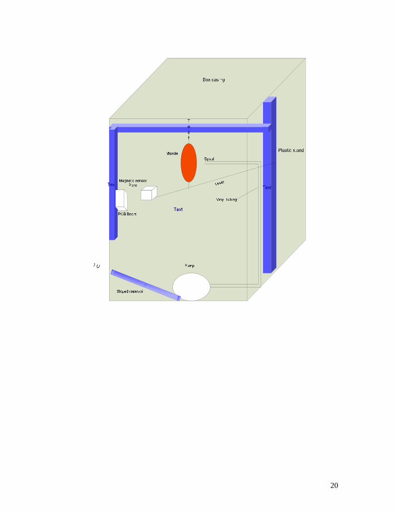
The device to be designed needs to be durable and relatively light in weight since it is not a stationary device. It will be a plastic enclosure consisting of a lever attached to a motorized track by means of a fulcrum. The muscle is attached to the lever by a clamp; a tray that holds weights is attached to the lever as well. On the opposite side of the enclosure, there is the Hall Effect system on a PCB board. The bottom contains a saline reservoir, a pump and a vinyl tube pipe that sprays the muscle specimen with saline in an aerosol manner. The setup will be connected to NI equipment and a computer with LabVIEW software.
The optimal design features more modifications than any other design to design process we have undergone so far. The optimal design had a brand new system setup radically different from its predecessors. Instead of an out in the open setup, a containment device was now proposed. A plastic box was added to the setup so that it would hold everything in place, and contain spatter from the saline solution spray. Also, a brand new saline spray system was introduced to the project in this stage. A completely new reservoir-pump-tubing system is suggested for moving the liquid upward the container, and then directly onto the muscle. Additionally, every support structure below is plastic, and thus will not deteriorate the way that steel would have in previous designs. These are the multiple creative innovations invoked on our optimal design. A diagram of the setup is shown below:
19
20

21

2.2.2 Subunits: 2.2.2.1 Equations: Newtonian mechanics equations:
Eq. 1) Fnet = ma
Eq. 2) Fnet = ∑ F
Eq. 3) Fnet = FgHall + FgLever + FgMasses - FtMuscle
Eq. 4) W = U + K Miscellaneous Equations:
Eq. 5) V = lwh
Eq. 6) V = IB
Eq. 7) σ= (Lf – Lo) / Lo
Newtonian mechanics are the fundamentals of basic physics. The equations in the basic mechanics of physics will tell us how objects will act when something happens to them. This applies true if the object is tiny as in the case of an atom, or will apply just as correctly to the study of great massive heavenly bodies. The only time these equations will fail is if the object in question starts to approach relativistic speeds. However, something needs to travel at 10% the speed of light in order to necessitate concern with the effect its velocity has on how much inertia it has. Our items are stationary, thus making these equations well suitable to describe the system. Equation 1 shows the relationship between force and acceleration. It shows that how much force acts on an object is directly proportional to its acceleration, and the constant of proportionality is the object’s mass. It further implies that if the net force on an object is 0, then the object will not accelerate. This is an equilibrium we hope to reach with the lever in our system, as the lever would be still if the net force acting on it were equal to 0. Also, if the net force on the lever were a non-zero value, as long as it is a known value, then that could be of value as well. If a force transducer were hooked up to the lever, it would find this value and then allow its use appropriately. The next equation, equation 2, allows the application of the idea of net force. It states that the net force acting on an object is equal to the sum of all forces acting on an object. The beauty of this formula is that it takes direction into consideration, as forces acting in one direction are labeled positive, and forces acting in the opposite direction are labeled negative. In our system, three forces act downward, which were labeled positive forces, and one acts upward, labeled a negative force. By going ahead and substituting these forces for sigma F into
22

equation 2, we arrive at equation 3. Equation 3 is simply the statement of how all the forces active on the lever shall equal the net force acting on the lever. Also, it labels every force that is active within the system. Plugging in values which are determinable into that equation will leave one unknown. This unknown will be the tensile force in the muscle, which is what is needed in conducting the project. As long as the equation reduces to one unknown, then its single variable value can be found. The 4th equation in this setup is part of classical Newtonian mechanics, but has nothing to do with force. The statement is born out of the law of conservation of energy. It is not a perfect equation, since it neglects a heat quantity called Q which does exist, but is assumed to be negligible. Each side of the equation shows a form of energy. In the process described in the design, water is being lifted by pump through a tube. That is another way of saying work is being done on the water solution, and it is given a greater potential and kinetic energy. Because energy is conserved, the work done on the water, otherwise seen as the change in its energy, must be equal to the new potential and kinetic energies it develops, plus the heat which it loses in the process. There is a very small amount of heat loss as the pump churns the water, developed from friction between the pump and water, and friction between water and the vinyl tubing as it travels up the tube. Because this quantity is very small relative to the rest of the system, it is ignored and the final applicable equation becomes W = U + K where W is work, U is potential energy, and K is kinetic energy. Equation 5 is a formula which is used to determine the volume of a rectangular prism. The plastic casing encompassing the whole design is of the shape of a prism, thus this equation applies to its volume calculation. The three known values are length, width, and height, and multiplying them all lead to its volume. Knowing its volume is extremely important since this dictates how big to build the box. The sixth equation is from classical description of magnetics and electricity in physics. It is the statement, V = IB, where V is voltage, I is current, and B is magnetic field. The correct form of this statement is actually V = I x B x sin θ, but since in most cases, theta equals 90 degrees, that term just becomes 1. Theta is a measure of the angle between the direction of current and the direction of the magnetic field. The product of all three of these terms outputs a voltage value, and this is exactly what the Hall Effect sensor does. Once this value is known, it can then be converted into length by using a correlation. The final equation used in this design is designed to calculate the strain of the muscle. Muscle strain, which is denoted σ, is equal to the change in length of the muscle divided by its original length. Its final length is denoted Lf, and its original length is denoted Lo. Mathematically, writing out change in length amounts to (Lf – Lo), and all that is left in the equation is dividing by the original length. [3]
23
2.2.2.2 Transducer
An integral piece of the device is the transducer. A transducer is a tool that converts one type of energy to another for various purposes including measurement or information transfer, it takes the analog reading of how much force is produced and translates it into digital code which is then readable by a computer. The LabVIEW® software is capable to acquire signals that will be provided via the User Interface. This acquisition can then be stored and read; in addition it can then be exported and used in Microsoft Excel. If a student were assigned to do this part of the task, it can easily comply with the existing materials. In reality students will need to use the device in a laboratory of one of a required course in the Biomedical Engineering department. Students will need to set up the experiment, record data, and write a program that would take the data with inputs and outputs like force, velocity, length, tension, shortening and lengthening aiming to make it work and obtain graphs of the force-velocity and length-tension relationships. Direct measurement of displacement arises in studying the contractility of isolated muscle and it can be done as a means of transducing a physical quality into electrical signals.
Force is defined through the equation F= M x A. As a result it depends on
two quantities: mass, which is a fundamental quantity; and acceleration, which is derived from two other fundamental quantities, length and time. The unit of the force is the Newton which is the force required to accelerate a mass of 1 kg by 1 m/sec^2. Since the earth’s gravitational acceleration is essentially constant with time and varies in a known manner with location and height, it provides an excellent means whereby known masses can be used to create an accurately calculable force. The static calibration of force transducers is usually carried out in this way. A means by which a force can be measured can be by balancing the unknown force against the gravitational force of a standard mass. Isometric conditions are achieved if the maximum displacement of the transducer is sufficiently small for it to have no significant effect on the force produced.
When external forces are applied to a stationary object, stress and strain are the result. Stress is defined as the object's internal resisting forces, and strain is defined as the displacement and deformation that occur. More specifically, strain is defined as the fractional change in length. For a uniform distribution of internal resisting forces, stress can be calculated by dividing the force applied by the unit area, and strain is defined as the amount of deformation per unit length of an object when a load is applied. Strain is calculated by dividing the total deformation of the original length by the original length. While there are several methods of measuring strain, the most common is with a strain gauge, a device whose electrical resistance varies in proportion to the amount of strain in the device. There are several methods of measuring strain, and the most common is with a strain gauge, a device whose electrical resistance varies in proportion to the amount of strain in the device. Force is defined through the equation Force =
24
Mass x Acceleration. The two quantities: mass which is a fundamental quantity; and acceleration which is defined from length and time. Measurement of isolated muscle under isometric conditions can be made by attaching one end of the muscle to a force transducer and the other end to a fixed frame of reference. Isometric conditions are achieved if the maximum displacement of the transducer is sufficiently small for it to have no significant effect on the force produced.
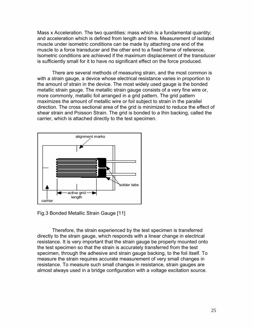
There are several methods of measuring strain, and the most common is with a strain gauge, a device whose electrical resistance varies in proportion to the amount of strain in the device. The most widely used gauge is the bonded metallic strain gauge. The metallic strain gauge consists of a very fine wire or, more commonly, metallic foil arranged in a grid pattern. The grid pattern maximizes the amount of metallic wire or foil subject to strain in the parallel direction. The cross sectional area of the grid is minimized to reduce the effect of shear strain and Poisson Strain. The grid is bonded to a thin backing, called the carrier, which is attached directly to the test specimen.
Fig.3 Bonded Metallic Strain Gauge [11]
Therefore, the strain experienced by the test specimen is transferred directly to the strain gauge, which responds with a linear change in electrical resistance. It is very important that the strain gauge be properly mounted onto the test specimen so that the strain is accurately transferred from the test specimen, through the adhesive and strain gauge backing, to the foil itself. To measure the strain requires accurate measurement of very small changes in resistance. To measure such small changes in resistance, strain gauges are almost always used in a bridge configuration with a voltage excitation source.
25

Fig. 4 Strain Gage Circuit Diagram, it shows that a strain gages are nothing more than resistors used with bridge circuits as shown.
Ideally, we would like the resistance of the strain gauge to change only in response to applied strain. However, strain gauge material, as well as the specimen material to which the gauge is applied, will also respond to changes in temperature. By using two strain gauges in the bridge, the effect of temperature can be further minimized in the way that a strain gauge configuration where one gauge is active (RG + DR), and a second gauge is placed transverse to the applied strain and the strain has little effect on the second gauge, called the dummy gauge.
Fig. 5 Use of Dummy Gauge to Eliminate Temperature Effects [11] PRIME STRAIN GAGE SELECTION CONSIDERATIONS
26

• Gage Length • Number of Gages in Gage Pattern • Arrangement of Gages in • Gage Pattern • Grid Resistance • Strain-Sensitive Alloy • Carrier Material • Gage Width
SPECIFICATIONS SGT SERIES Foil Measuring Grid Constantan foil 5 microns thick Carrier Polyimide Substrate Thickness 20 microns Cover Thickness 25 microns Connection Dimensions: mm (in) Solder pads or ribbon leads,
tinned copper flat wire 30 L x 0.1 D x 0.3 W (1.2 L x 0.004 Dia. x 0.012 W); other wire types available upon request Stated in “To Order” box
Fig. 4 Strain Gages
27
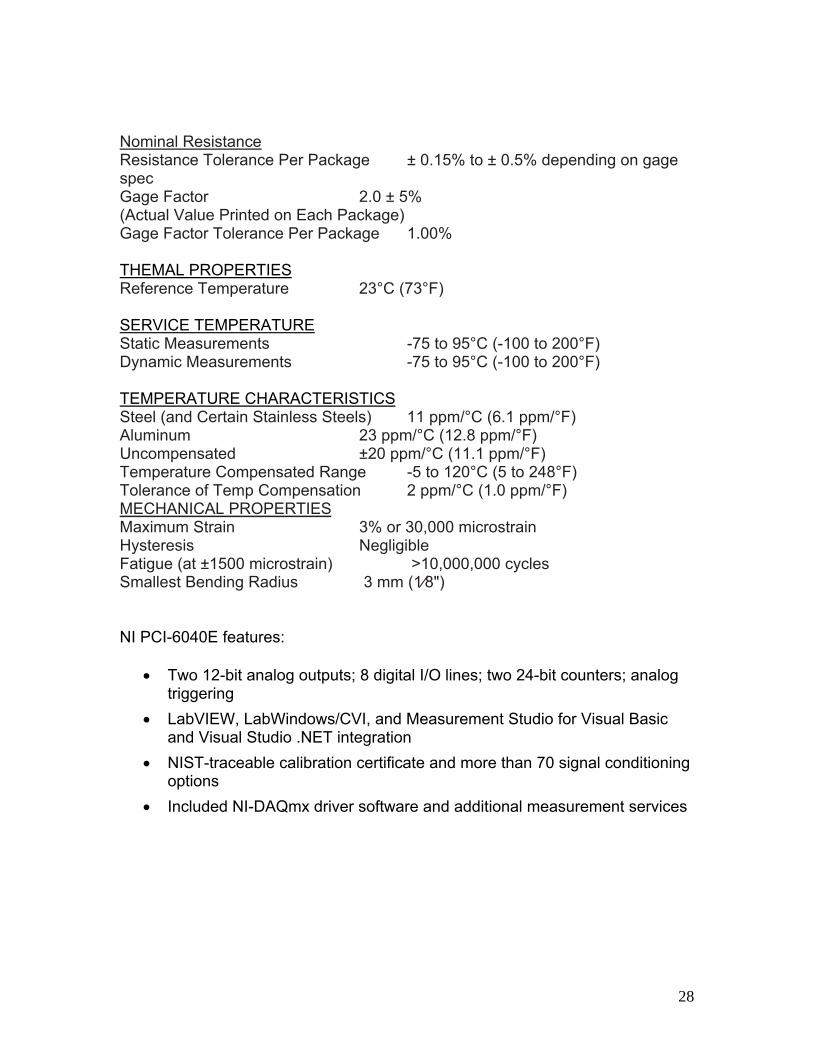
Nominal Resistance Resistance Tolerance Per Package ± 0.15% to ± 0.5% depending on gage spec Gage Factor 2.0 ± 5% (Actual Value Printed on Each Package) Gage Factor Tolerance Per Package 1.00% T THEMAL PROPERTIES Reference Temperature 23°C (73°F) SERVICE TEMPERATURE SERVICE TEMPERATURE Static Measurements -75 to 95°C (-100 to 200°F) Dynamic Measurements -75 to 95°C (-100 to 200°F) TEMPERATURE CHARACTERISTICS TEMPERATURE CHARACTERISTICS Steel (and Certain Stainless Steels) 11 ppm/°C (6.1 ppm/°F) Aluminum 23 ppm/°C (12.8 ppm/°F) Uncompensated ±20 ppm/°C (11.1 ppm/°F) Temperature Compensated Range -5 to 120°C (5 to 248°F) Tolerance of Temp Compensation 2 ppm/°C (1.0 ppm/°F) MECHANICAL PROPERTIESMECHANICAL PROPERTIES Maximum Strain 3% or 30,000 microstrain Hysteresis Negligible Fatigue (at ±1500 microstrain) >10,000,000 cycles Smallest Bending Radius 3 mm (1⁄8") NI PCI-6040E features:
• Two 12-bit analog outputs; 8 digital I/O lines; two 24-bit counters; analog triggering
• LabVIEW, LabWindows/CVI, and Measurement Studio for Visual Basic and Visual Studio .NET integration
• NIST-traceable calibration certificate and more than 70 signal conditioning options
• Included NI-DAQmx driver software and additional measurement services
28
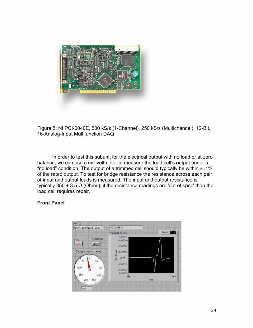
Figure 5: NI PCI-6040E, 500 kS/s (1-Channel), 250 kS/s (Multichannel), 12-Bit, 16-Analog-Input Multifunction DAQ
In order to test this subunit for the electrical output with no load or at zero balance, we can use a millivoltmeter to measure the load cell’s output under a “no load” condition. The output of a trimmed cell should typically be within ± .1% of the rated output. To test for bridge resistance the resistance across each pair of input and output leads is measured. The input and output resistance is typically 350 ± 3.5 Ω (Ohms); if the resistance readings are 'out of spec' than the load cell requires repair.
Front Panel
29
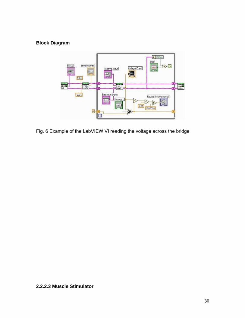
Block Diagram
Fig. 6 Example of the LabVIEW VI reading the voltage across the bridge 2.2.2.3 Muscle Stimulator
30

The muscle has to be stimulated by an electric pulse of about 12 mA so
that th
o
he
be re
the
e will like to use a real-time functional electrical stimulation system that deliver
e
s
ing or
lements needed: tion (DAQ)
CI
Requirements:
• Operate under isometric and nonisometric modes
• eliver the stimulation patterns with negligible timing errors between each
• odulate or truncate the stimulation trains automatically at the user-t
s
e muscle responds by contracting. In the body, this is done by the naturalsource of the motor unit, the nervous tissue which directly connects to the musclefiber. In our case of this fabricated version of contracting a muscle, a muscle stimulator, should be used as opposed to the natural motor unit source in the body. A muscle stimulator is simply a current pulse which is directly attached tskeletal muscle. LABView® is capable of being programmed to deliver this current pulse on its own, and this would be a cheaper way of implementing tstimulation since LabVIEW® already exists in the setups of this lab. The LabVIEW® program dictating how much current should be applied shouldwritten by our group, and not left to be the responsibility of the students who agoing to actually use the setup in the Biomesurements laboratory. Once the software starts the stimulation sent to the muscle, it records the voltage from Hall Effect sensor against the time.
Ws customized stimulation patterns, acquire and store data, monitor the
muscle responses to stimulation, and modify the stimulation patterns in real timto reflect physiological alterations in muscle responses. Using the multithreading capabilities of LABView® to simultaneously deliver stimulation patterns through a PCI-6602 board, acquire and monitor the data through two PCI-6024E boards, and modify the stimulation patterns in real time to reflect physiological alterationin muscle responses seem to be a good way of stimulating the muscle. FES (functional electrical stimulation sytem) is the use of electrical stimulation to activate artificially the muscles of patients with central nervous system dysfunction to help them to restore functional movement, such as standwalking. E
• Data Acquisi• LabVIEW® • PXI/CompactP
Dpulse and between each train Mdefined muscle performance level, such as switching from a constanfrequency train to a variable frequency train when the muscle force fall
31

below a desired level due to fatigue
• Acquire and store muscle performance data for subsequent analysis
• Write the data in a form that is compatible with existing analysis software
• Interface easily with the user
• Provide safety mechanisms to prevent undue stimulations being delivered to the patient
For electrical simulation, a pair of electrodes can be placed on the muscles for electrical stimulation. A Grass stimulator driven by a PC to stimulate the muscles through the electrode pair can be used. Timed Transistor Logic (TTL) pulses from the PC drive the Grass stimulator. The Grass stimulator puts out a corresponding amplified pulse at each rising edge of the TTL pulse. Then the amplified pulse is delivered to the patient’s muscle through electrodes placed on the muscle. When there is no motion, the muscle contraction as isometric. Isometric contraction involves an increase in muscle tension without a change in muscle length. When there is motion, the contraction is nonisometric, or isotonic. Isotonic contraction involves an increase in muscle tension with an accompanied change in muscle length. Using a DAQ board to collect and store muscle force, angular position, and velocity data on the PC for later analysis is needed.
32

Fig. 7 Muscle Stimulation Set Up DAQ Boards:
DAQ board is a basic A/D converter coupled with an interface that allows
a personal computer to control the actions of the A/D, as well as to capture the digital output information from the converter. A DAQ board is designed to plug directly into a personal computer's bus. All the power required for the A/D converter and associated interface components is obtained directly from the PC bus.
PXI:
PXI (PCI extensions for Instrumentation) is a rugged PC-based platform
for measurement and automation systems. Features:
• Rugged, compact package with slots for five peripheral modules
33

• Compact chassis for remote controllers or 1 or 2-slot embedded controllers
• Compatibility with both 3U PXI and Compact/PCI modules
• Quiet acoustic noise emissions as low as 41 dBA
• 300 W universal AC power supply
• Low-cost, low-power system ideal for remote, real-time, and data acquisition applications
Fig.8: NI PXI-1036 6-Slot 3U PXI Chassis with AC
34
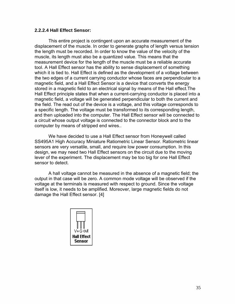
2.2.2.4 Hall Effect Sensor: This entire project is contingent upon an accurate measurement of the displacement of the muscle. In order to generate graphs of length versus tension the length must be recorded. In order to know the value of the velocity of the muscle, its length must also be a quantized value. This means that the measurement device for the length of the muscle must be a reliable accurate tool. A Hall Effect sensor has the ability to sense displacement of something which it is tied to. Hall Effect is defined as the development of a voltage between the two edges of a current carrying conductor whose faces are perpendicular to a magnetic field, and a Hall Effect Sensor is a device that converts the energy stored in a magnetic field to an electrical signal by means of the Hall effect.The Hall Effect principle states that when a current-carrying conductor is placed into a magnetic field, a voltage will be generated perpendicular to both the current and the field. The read out of the device is a voltage, and this voltage corresponds to a specific length. The voltage must be transformed to its corresponding length, and then uploaded into the computer. The Hall Effect sensor will be connected to a circuit whose output voltage is connected to the connector block and to the computer by means of stripped end wires..
We have decided to use a Hall Effect sensor from Honeywell called
SS495A1 High Accuracy Miniature Ratiometric Linear Sensor. Ratiometric linear sensors are very versatile, small, and require low power consumption. In this design, we may need two Hall Effect sensors on the circuit due to the moving lever of the experiment. The displacement may be too big for one Hall Effect sensor to detect.
A hall voltage cannot be measured in the absence of a magnetic field; the output in that case will be zero. A common mode voltage will be observed if the voltage at the terminals is measured with respect to ground. Since the voltage itself is low, it needs to be amplified. Moreover, large magnetic fields do not damage the Hall Effect sensor. [4]
35

The Hall Sensor device has four terminals, and it produces a voltage output. Its voltage is relative to the current, magnetic field, and the angle. The equation can be generalized to:
Where V is the voltage, I is the current, and B is the magnetic field. Included below is a table of specifications for the Hall Affect sensor:
In order to test the functioning of the Hall Effect circuit, we plan to build a virtual circuit using Pspice and troubleshooting it. After we are certain the circuit functions properly, we will continue to physically build the circuit on our PCB board.
36

2.2.2.5 PCB Board: During the course of Senior Design two, we should have a circuit board printed out for us to use as part of the setup. The printed circuit board (PCB) will include a general amplifier, resistors, a 5 Volts regulator, potentiometer, and finally, the Hall Effect Sensor. The voltage vs. time measurement obtained from the Hall Effect sensor is used to calculate the distance of contraction. Velocity is obtained from the distance and the time recorded. After that, the length-tension and force-velocity (for both shortening and lengthening) calculations are acquired from Excel and displayed on graphs after the data is exported from LabVIEW, or directly from LabVIEW. Before we print out the PCB board, we should build a similar model virtually using Pspice, and physically using breadboard designs to ensure that the system is working properly. The software to design the PCB boards can be obtained from www.expresspcb.com. After we obtain the PCB, we can solder the components such as resistors and Hall Effect sensor, and then mount the circuit to its designated place in the plastic enclosure.
37

2.2.2.6 Plastic casing The best approach to forming the plastic casing is to start off with sheet plastic and then bend it. After that, a hinge will be put on the front panel in order to make the inside accessible, like a door. The plastic will be bent into a rectangular prism with dimensions shown above. Therefore, the amount of plastic required is going to be the surface area represented by those dimensions. The formula for surface area of a rectangular prism is SA = 2(lw) + 2(hw) +2(lh). With our given dimensions of 30 x 30 x 40 this equals out to 6600 cm2. The company which we intend to purchase this product from is called MSC Industrial Supply
Company. An image they offered of their product was this: Using machinery which we hope to master in a machine shop class, we will mold this plastic into the proper shape. This plastic is called Premium Grade UHMW-PE Sheets Material: Polyethylene - Anti-Static UHMW. One exciting attribute about this plastic is that it is fairly malleable, so we will be able to use it with hopefully a certain amount of ease during the machining of it. The reason for the plastic casing is the modification which we made on the original design. One issue with our project all along was that it was considered a remake of previous existing works, and did not involve many innovative processes to make it a true creative design. A description is well different from a design, and up until this point our project was not distinguishable from anything else done in the past. What defines our project now is the enclosure of all the subunits involved with it. An innovation we developed is to house a muscle stimulator in a containment dome, and it qualifies our project as a brand new design, something we came together and made that had not existed in any way shape or form before. Beyond just housing all the equipment that is supposed to be in the structure, the containment plastic box acts as a spatter shield. Saline solution will splish and splash a little bit as it is applied to the muscle. In previous muscle stimulation labs, it simply would get moisture all over the place, making for a messy lab environment. This casing is an innovative way of keeping the work station clean, and not allowing for a wet lab surface.
38
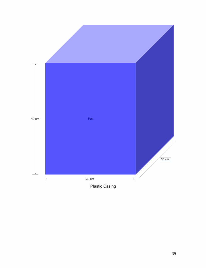
Text
30 cm
40 cm
30 cm
Plastic Casing
39

2.2.2.7 Sloped reservoir Another innovation which we developed is the reuse of saline solution. Saline solution is squirted and then falls to the bottom, and then it is never used again. In a fairly wasteful process, it is utilized one time, reaches the lab table, and that particular amount of liquid is then considered finished. Our innovation of a sloped reservoir hopes to reuse saline, and thus reduce cost of the overall laboratory price. The slope is going to be a simple acrylic sheet, soldered into the left and bottom sides of the plastic casing. Then what would happen is saline hits the reservoir and easily slides down the slope into a water pump. The pump would next channel water from the bottom of the tank up into the top of the tank. It would send this through an acrylic tubing attached to a plastic stand vertically oriented along the right side of the box. Then the solution would exit the tubing via a spray spout on the end the tubing. This is the whole slaine collection system which we have developed. The reservoir is intended to be built from one acrylic sheet. An acrylic sheet is a good choice because it is a form of plastic which is durable, and will not bend under small amount of force. The acrylic sheet we will choose to work with is supplied by United States Plastic Corporation. They build a durable product, which has other features which we find ideal for the purposes of this project. Fabrication from this sheet is simple. All that is needed is for the sheet to be sawed to dimensions with fine tooth blades, drilled with plastic drills, then sanded, and finally polished. An example of what multiple sheets look like is available below.
40
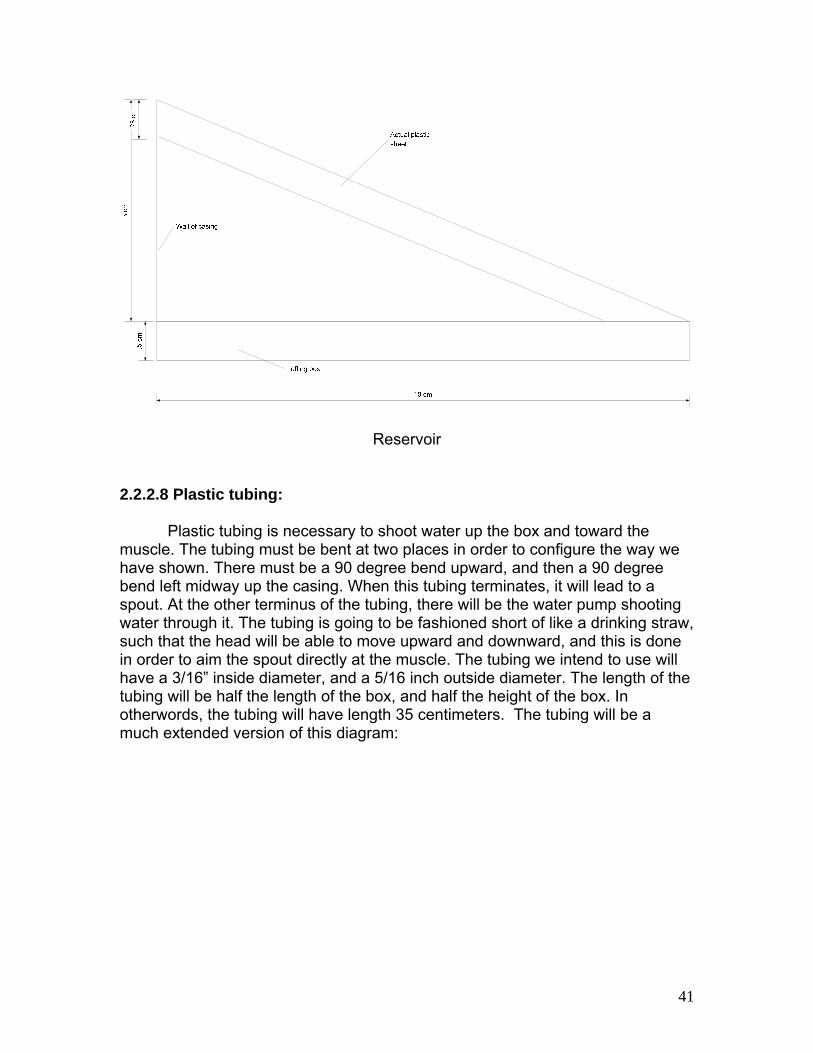
Reservoir
2.2.2.8 Plastic tubing: Plastic tubing is necessary to shoot water up the box and toward the muscle. The tubing must be bent at two places in order to configure the way we have shown. There must be a 90 degree bend upward, and then a 90 degree bend left midway up the casing. When this tubing terminates, it will lead to a spout. At the other terminus of the tubing, there will be the water pump shooting water through it. The tubing is going to be fashioned short of like a drinking straw, such that the head will be able to move upward and downward, and this is done in order to aim the spout directly at the muscle. The tubing we intend to use will have a 3/16” inside diameter, and a 5/16 inch outside diameter. The length of the tubing will be half the length of the box, and half the height of the box. In otherwords, the tubing will have length 35 centimeters. The tubing will be a much extended version of this diagram:
41
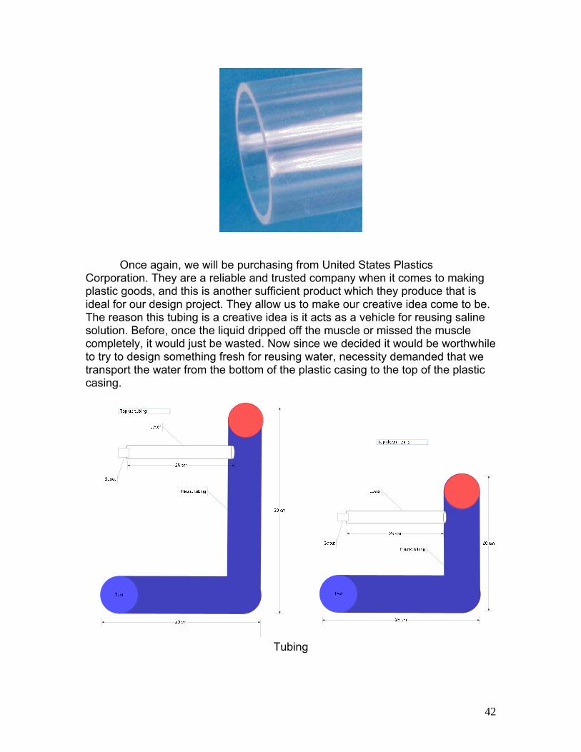
Once again, we will be purchasing from United States Plastics Corporation. They are a reliable and trusted company when it comes to making plastic goods, and this is another sufficient product which they produce that is ideal for our design project. They allow us to make our creative idea come to be. The reason this tubing is a creative idea is it acts as a vehicle for reusing saline solution. Before, once the liquid dripped off the muscle or missed the muscle completely, it would just be wasted. Now since we decided it would be worthwhile to try to design something fresh for reusing water, necessity demanded that we transport the water from the bottom of the plastic casing to the top of the plastic casing.
Text
Tubing
42
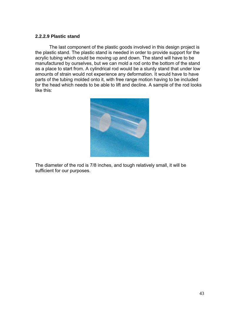
2.2.2.9 Plastic stand The last component of the plastic goods involved in this design project is the plastic stand. The plastic stand is needed in order to provide support for the acrylic tubing which could be moving up and down. The stand will have to be manufactured by ourselves, but we can mold a rod onto the bottom of the stand as a place to start from. A cylindrical rod would be a sturdy stand that under low amounts of strain would not experience any deformation. It would have to have parts of the tubing molded onto it, with free range motion having to be included for the head which needs to be able to lift and decline. A sample of the rod looks like this:
The diameter of the rod is 7/8 inches, and tough relatively small, it will be sufficient for our purposes.
43
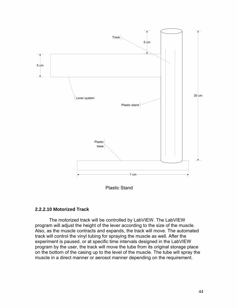
7 cm
30 cm
5 cm
5 cm
Lever system
Plastic stand
Plastic base
Track
Plastic Stand 2.2.2.10 Motorized Track The motorized track will be controlled by LabVIEW. The LabVIEW program will adjust the height of the lever according to the size of the muscle. Also, as the muscle contracts and expands, the track will move. The automated track will control the vinyl tubing for spraying the muscle as well. After the experiment is paused, or at specific time intervals designed in the LabVIEW program by the user, the track will move the tube from its original storage place on the bottom of the casing up to the level of the muscle. The tube will spray the muscle in a direct manner or aerosol manner depending on the requirement.
44
2.2.2.11 Computer Software
Acquire data with LabVIEW®
National Instruments LabVIEW® is designed to make interfacing with any measurement hardware simple. With interactive assistants, code generation, and connectivity to thousands of devices, LabVIEW® makes gathering data as simple as possible. Because LabVIEW® provides connectivity to virtually any measurement device, you can easily incorporate new LabVIEW® applications into existing systems without losing your hardware investment. Regardless of your hardware requirements, LabVIEW® provides an interface to make connecting to Input/Output (I/O) easy. With National Instruments LabVIEW®, you can acquire and generate signals from plug-in boards, USB devices, and Ethernet-based systems. These I/O capabilities, combined with special data types and measurement analysis functions, are specifically designed to get the measurements you need from your physical sensors as quickly and easily as possible.
Measurements with LabVIEW® include:
• Temperature • Voltage • Resistance • Pressure • Strain • Current • Pulse • Force • Vibration • Frequency • Period • Sound • Light • Digital Signals
Analyze Data with LabVIEW®
National Instruments LabVIEW® software has more than 600 built-in
functions for signal synthesis, frequency analysis, probability, statistics, math, curve fitting, interpolation, digital signal processing, and more. You can also extend NI LabVIEW® with application-specific processing for sound and vibration, machine vision, RF/communications, transient/short-time duration signal analysis, and others. With LabVIEW®, you can choose among multiple
45
programming approaches to implement math, signal processing, and analysis. This gives you the freedom to select the most appropriate approach for the problem or situation.
One case is that one can work with graphical dataflow programming, a
fundamental part of LabVIEW® that resembles a block diagram. For text, you can work with MathScript, a textual math-oriented programming language with both interactive and programmatic interfaces. For additional flexibility, one can easily integrate external software with the LabVIEW® applications. For instance, one can call on custom signal processing or math from a DLL or third-party software such as Microsoft Excel or The MathWorks, Inc. MATLAB® software.
Present Data with LabVIEW®
After one acquires and performs analysis on the data, one likely needs to present the data. Data presentation encompasses data visualization, report generation, data storage, Web publishing, database connectivity, data management, and more. The National Instruments LabVIEW® graphical development environment includes hundreds of built-in functions and tools for data presentation, and one can add more functions with application-specific NI LabVIEW® toolkits.
Visualize Data
It is challenging to effectively present data with spreadsheets and text files. Using LabVIEW®, you graphically can present your data with a wide array of user interface (UI) objects such as charts, graphs, thermometers, and 2D and 3D visualization tools. You even can configure object attributes such as color, font size, and graph type, as well as dynamically rotate, zoom, and pan graphs with no programming.
46

Synchronization with a Reference Clock [5]
Design Professional Interfaces
LabVIEW®, designed specifically for engineers and scientists, provides hundreds of measurement-specific UI objects to help you quickly develop a professional UI. Simply drag and drop built-in objects onto your UI and use interactive property pages to customize object behavior.
Creating a simple cone-shaped object [5]
Efficiently Store Data in Multiple File Formats
Quickly write your data to textual and binary file formats using the LabVIEW® Storage Virtual Instrument’s (Vis) and File I/O VIs. You can also include custom meta data with your data files to help you extract useful information later.
47
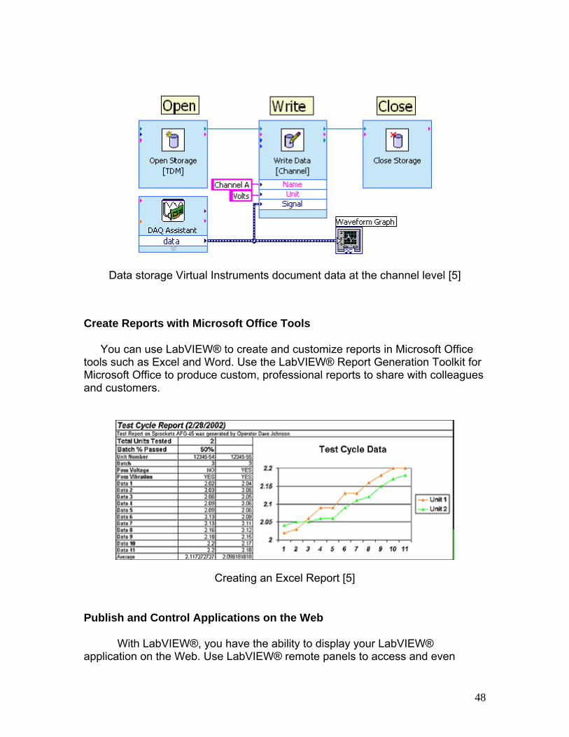
Data storage Virtual Instruments document data at the channel level [5]
Create Reports with Microsoft Office Tools
You can use LabVIEW® to create and customize reports in Microsoft Office tools such as Excel and Word. Use the LabVIEW® Report Generation Toolkit for Microsoft Office to produce custom, professional reports to share with colleagues and customers.
Creating an Excel Report [5]
Publish and Control Applications on the Web
With LabVIEW®, you have the ability to display your LabVIEW® application on the Web. Use LabVIEW® remote panels to access and even
48
control your VI across the Web and implement security settings to safeguard your data.
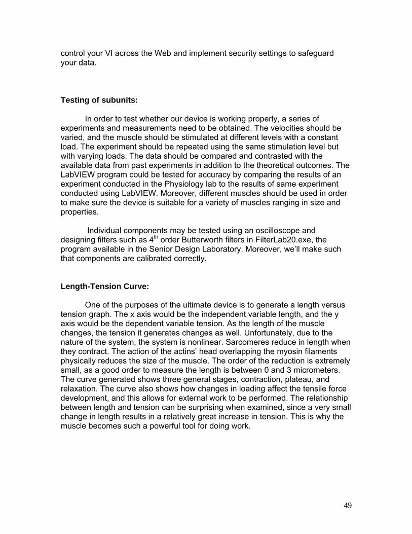
Testing of subunits:
In order to test whether our device is working properly, a series of experiments and measurements need to be obtained. The velocities should be varied, and the muscle should be stimulated at different levels with a constant load. The experiment should be repeated using the same stimulation level but with varying loads. The data should be compared and contrasted with the available data from past experiments in addition to the theoretical outcomes. The LabVIEW program could be tested for accuracy by comparing the results of an experiment conducted in the Physiology lab to the results of same experiment conducted using LabVIEW. Moreover, different muscles should be used in order to make sure the device is suitable for a variety of muscles ranging in size and properties.
Individual components may be tested using an oscilloscope and
designing filters such as 4th order Butterworth filters in FilterLab20.exe, the program available in the Senior Design Laboratory. Moreover, we’ll make such that components are calibrated correctly. Length-Tension Curve: One of the purposes of the ultimate device is to generate a length versus tension graph. The x axis would be the independent variable length, and the y axis would be the dependent variable tension. As the length of the muscle changes, the tension it generates changes as well. Unfortunately, due to the nature of the system, the system is nonlinear. Sarcomeres reduce in length when they contract. The action of the actins’ head overlapping the myosin filaments physically reduces the size of the muscle. The order of the reduction is extremely small, as a good order to measure the length is between 0 and 3 micrometers. The curve generated shows three general stages, contraction, plateau, and relaxation. The curve also shows how changes in loading affect the tensile force development, and this allows for external work to be performed. The relationship between length and tension can be surprising when examined, since a very small change in length results in a relatively great increase in tension. This is why the muscle becomes such a powerful tool for doing work.
49
Force-Velocity Curve: The other curve hoped to be developed by the experiment is a curve analyzing force versus velocity. On this graph, velocity is the independent variable on the x axis, and force is the dependent variable on the y axis. The way the relationship develops is that a muscle undergoes shortening and lengthening under constant loads. In the case of this lab design, the constant load shall be the weight applied which is physically connected to the muscle. The velocity during shortening is measured by the devices already set in place, and the resistive force is recorded from the force transducer. Physiologically, the basis for the relationship is the quantitative result of the number of time for force bridges to attach. Though a muscle acts quickly, (within less than half a second when excited), it takes a few milliseconds for the cross bridges to form. As cross bridges attach, filament velocity increases. However, from the same process, force decreases from the fewer quantity of filaments now attached. The converse of this situation also holds to be true as well. If filament velocity decreases, more cross bridges have an opportunity to attach, and thus more force will be generated by the muscle. Ultimately, the determining factor for the shape of the force-velocity curve is the number of filaments that have developed cross bridges at that point. The two terms are related inversely, and as velocity goes up force goes down. As force goes up, velocity goes down.
50

Testing required for the relationships
• Obtain fresh muscle for experiments to be conducted • Creation and design of a working Hall effect sensor circuit • Testing and calibration • Measuring the rate of shortening and lengthening of muscle contraction
under different loads • The use of the lever arm for isometric conditions to reduce the force of
gravity and the inertial force of the load at the muscle • A variable for change in muscle length from the resting length • To experiment when the muscle is first stretched to its optimal length to
the start of the isotonic experiment Isotonic Contraction Experiment
• Muscle will shorten to exert a tension greater than the external load • Stimulate muscle • Record the position • Repeat experiment with different loads at same stimulation level • Obtain and calculate maximum velocity from position data
Force-Velocity Curve
• Begin the recording • Stimulate muscle once at maximal stimulus (to show when muscle
shortens with no load • Place five grams (5 g) of weigh to the lever arm • Allow it to stop moving
51

• Stimulate several times at each weight until muscle can no longer lift the load
• Measure height of the response at the peak for each recording in millimeters (mm)
• Record time required for each peak of the contraction in seconds (s) • Calculate the velocity (v), average of distance (mm) by the average of time
(s) Isometric Contraction Experiment
• Experiment at constant length • Measure and record the minimum physiological length of the muscle • Record at zero • Place five grams (5 g) of weight • Calibrate • Tighten muscle • Position stimulator electrode • Moist periodically the muscle • Record position and force
Length-Tension Relationship
• Set muscle at shortest physiological length • Calibrate at zero grams (0 g) • Deliver a single pulse at maximum stimulus • Change to new length • Calibrate • Stimulate • Record amount of tension produced a this length • Change length again • Calibrate • Wait few minutes • Enter a new length • Stimulate • Repeat as many times as necessary • Stimulate at its longest physiological length • Reset muscle to its shortest length • Wait few minutes • Stimulate • Record tension
52

3. Realistic Constraints: Based on the optimal design, the muscle recorder incorporates engineering
standards including, but not limited to, realistic economic, environmental, sustainability, manufacturability, ethical, and health and safety constraints. As an engineering standard we will be measuring and calculating in the International System of Units (SI) units. If at some point we come across English units the SI equivalents would be calculated and given. Moreover, we will the previously mentioned equations to calculate force, velocity, tension, and displacement.
Economically, this project needs to consider the available budget. Even though we do not have a given budget our aim is to keep the cost low since it would be nice to be able to install at least more than one muscle recorder station. We should use materials NI and LabVIEW® software. This device will not need a high maintenance cost since the parts we want to purchase would be durable.
Environmentally, this product does not induce noise to the students or faculty. The saline solution we use is made up of solution of sodium chloride, or salt, in sterile water. This solution is used for many application dealing with patients that can not eat or drink, used for contact lenses, and it also used to promote nasal health, therefore it can be rinsed or dumped down the drain and will not be a water contaminant. Since we are dealing with muscles, the only environmental concern as part of the design would be the appropriate handling and disposal of the muscle. At the end of each experiment, students or faculty will need to get rid of the muscle but in needs to be done in the correct manner. It needs to be placed in a waste disposal bag for waste disposal service, or one can wrap the remains in a lot paper and tie securely to prevent spillage. This can be placed in a plastic bag and it need to be refrigerated until garbage collection.
The sustainability is also an important aspect of our design since the durability and life span under the operation conditions should be considered. The durability will depend on the handling of the students, proper cleaning if any saline solution is spilled, and the temperature at which the device is being exposed. Most of the time, the labs are kept under a moderate temperature. Furthermore, the recorder is durable. The only items that will need to be replaced would be the muscle to be tested and the saline solution.
The manufacturability of the device is challenging yet within our capabilities. The manufacture of it should not harm any one in the process or in the testing. The measurements are taken easily with the help of measurement devices and the usage of the NI program represents no problem at all. Since we are aimed at making this device as light as possible it would get easier for students or faculty to move the device around as needed. Most importantly, all the items we need for the design of the device are available and are found very easily.
53
Ethically, this product is designed considering the safety and health of the users. None of the parts are chosen for appearance over safety. This technological device therefore does not violate the code of ethics because no one using the device will be put at risk, results will be reproducible and students will gain knowledge in more than one subject. Plagiarism is not a problem in this design since research has been done, and we haven’t found a device that will perform the different aspects of our device including, but not limited to, the use of NI and LabVIEW® software to stimulate the muscle, the lengthening of the muscle, and the automated spraying of the solution. Some people think that is not right experimenting with different parts of animals and some might not even want to participate in experiments that treat with animal parts. Gloves are going to be provided in order to handle and touch the animal muscle but for some people just the thought of seeing the flesh of a dead animal might be sickening. Since this lab will be performed in teams, hopefully if this is the case for any students, the rest can do the set up while that student performs other tasks.
Health and safety are the most important aspects of a design. This device doesn’t contain any allergens and is safe for users who know how to operate it. As stated before no noise in the design will be enough to cause hearing loss or harm anyone at this level. None of the products used are toxic, hazardous, or radioactive. Proper disposal of the muscle was described above to prevent any hazard. As mentioned earlier, the saline solution is not toxic but items should be cleaned after using this solution. When the stimulus is programmed by the software, the needles should always be connected to the muscle even if the voltages used in the experiment are not extremely dangerous.
54

4. Safety Issues:
Based on the design, electrical, mechanical, biological and chemical hazards are safety issues that need to be taken into consideration. All the materials are safe for the users. Even in the case of the gloves, which are used for hygienic purposes when handling the animal muscle, we decided to also include free-latex gloves since some students may be allergic to latex. Electrically, there is no risk for students or faculty because no direct contact of parts connecting others is necessary. Only when handling the needles to the muscle attention must be present since voltage will be produced. The NI equipment is safe to work with since the safety of it was tested by the company. The set up is designed in a way that it is sturdy and set up in a table station so no worries for cables being around or tripping on them are necessary.
One of the major safety issues in the experiment with the design will be the usage of animal muscle. This issue includes biological and chemical hazards. We are going to be dealing with raw materials that are going to be in storage prior to use, therefore one needs to be sure that the product has been properly handled in a way that pathogen contamination is minimized, e.g., letters or certificates of guarantee, product temperature tracking, and microbial testing. There are chemicals that are present in order to preserve dead specimen, and these can contaminate water, soil, people, and wildlife in they are not disposed properly. These chemicals can also be irritating or harmful to humans, therefore gloves must be work at all times, and proper disposal of the muscle is crucial to prevent biological hazards like cancer of the throat, lungs, risk damage to the eyes, skin irritation, bronchitis, asthma attacks and nasal passages. Since great amounts of these chemicals will not be around, students should not be worried about being exposed to the mentioned hazards but prevention and good handling of the muscle will minimize any risk even if it is a small one. If human muscle tissue is used, IRB approval must be met. We are limited to using small animal muscles and are thus not required to obtain IRB approval.
55
5. Impact of Engineering Solutions:
The optimal design of the muscle recorder has global, economic, environmental, and societal impacts. With the help of the muscle recorder device and its applications with the use of NI and LabVIEW® software, students would be able to appreciate the impact of the Biomedical Engineering solutions for this particular device and the experiment that is performed with its help.
This device is used globally since virtually everyone is familiar with muscle contractions and how they affect our organism and every activity we perform. Some might not be fully aware of the different types of contractions and how they are related and different from each other, or how one can obtain measurements and graphs from experiments. One thing is for sure and it is that through out the world, experiments with muscles dealing with contractions are being made in order to gain more knowledge about this important aspect of our lives since it can affect every single task we perform. We know that for example in the University of Connecticut, the Physiology and Neurobiology department has a lab for the Human Physiology and Anatomy course that currently measures contractions in a frog muscle basically for the shortening or concentric contraction of the muscle using different forces. Moreover, both NI equipment and the LabVIEW software are used internationally.
Economically, this device should not impact engineering solutions for the reason that all the components needed for the design of the device are relatively inexpensive compared to other market prices, and the only expensive items included would be the software and the computer. The software and the computer in this case should not be an issue to be concerned about as we have these items offered by the Biomedical Engineering Department and the students using this devices will be students enrolled in this particular program. Replacing parts for this device is non-expensive and the cost can be maintained to the lowest since the lab can use one set up of the device and teams can take turns to perform the experiment. It would be really nice if more than one station was available as it would let students spend more time with the device since students will need at least twenty different forces to be measured in order to obtain maximum contraction velocity. We think that the more time students spend during the experiment, the more knowledge students will be able to get out of it.
The use of the muscle recorder can help to find out if activities are not being performed in a right manner or if unusual things are happening inside the muscle or the system the muscle belongs to, or if certain movements or activities are not being executed as is supposed to and to its maximum range. It also helps athletes to perform at their highest potential by finding out the relationships of force-velocity and length-tension. Failure for a variety of sports can also be detected from quadriplegic to elite athletes. For power athletes it seems that eccentric contraction movements are more useful than concentric ones.
56

Environmentally, the design of this product will mean little harm to the ecosystem and other people. The materials used in the set up can be fully thrown away or recycled after they no longer functioning or if any part needs to be replaced. As mentioned earlier, proper disposal of the muscle and gloves should be followed to prevent biological or chemical hazards. The environment in which the device and the experiment are located would also make a great difference. People need to be aware that dealing with electronic devices would mean good storage, proper cleaning, no extreme temperatures or harsh conditions.
In a societal context this design and all the aspects that make part of it can greatly impact the way people see and use the features of the muscle recorder. Students in general will be able to know that skeletal muscles produce a force that is proportional to the muscle length - which will be specified as the Length-Tension relationship. The other force would be the muscle contraction velocity – which in this experiment is known as the Force-Velocity relationship. There are many classes, labs, books, literature that try to teach basic features of the muscle and how it can be stimulated to give meaningful results using data in graphs. None of the found experiments include the extra features we are adding to this new device and we are sure that students will greatly appreciate this advancement in the field because it does not only give you knowledge about muscle contractions, relationships, usage of NI and LabVIEW® software but in addition it serves as a tool for future students to really think about the applications behind the experiment and the way this device can be redesigned to add features as well as to develop more accurate techniques in a future. Society can greatly be benefited from the experiments this device will be able to reproduce since as mentioned earlier, some of these measurements can efficiently help athletes and the way they can perform in different activities. Many people are not aware that many of the injuries and soreness that one can experience happen during the eccentric or lengthening contraction. Therefore, by fully having access to the understanding of these aspects people and especially athletes can be prevented from performing wrong activities that can lead to harm to different muscles.
57
6. Life-long Learning:
In the process of designing our muscle recorder, new knowledge and techniques were acquired. By researching about different components such as the Hall Effect sensor and the transducer, we learned about the functions of these components as well as the ways we can incorporate them in our design. We also learned about the different types of contractions, what they mean, how they are measured, and put into graph by researching the background of the muscle recorder.
Although we were familiar with the LabVIEW software, at first it didn’t
occur to us to operate the device using a LabVIEW program. LabVIEW; however, has a wide spectrum of applications, and we realized that it would be innovative to create a LabVIEW automated muscle recorder. Dealing with and creating a LabVIEW program is always a challenging and rewarding experience because this program has so many features and so many different ways of creating something.
Other things we learned include team management, performing patent
searches, using different Microsoft applications, and using Dreamweaver to set up a website. The skills learned throughout the senior design project will be very helpful in industry. In industry, it is vital to be familiar with the process of researching, designing, testing, and building a product.
Our group had a rough start; as one underestimated the amount of time
and effort that had to put in designing an innovative instrument. There is a great difference between designing and building a device and between operating it in a lab setting, as one should fully understand each aspect of the design that is being performed and demonstrated. Moreover, extensive research is required in order to design the most effective and accurate device based on the client’s requirements, and if one isn’t willing to do the research, the project will be lacking in more than one aspect.
Due to people’s conflicting schedules, it is very hard to work with others, but this project gives students the opportunity to come together with ideas in order to compile them in a single project trying to achieve the best possible result to offer the client. One needs to develop a higher level of thinking since a project like this has never been introduced and it is easy to make a lot of mistakes as one is not thinking professionally as it is done in the industry. One should also improve on his time management techniques, since procrastination has detrimental effects on the project in hand. And last but not least, communication about the progress made regarding the project is essential, and lack of communication proved to be problematic.
58

7. Budget and Timeline:
7.1 Budget:
In this table we list the cost of the products needed in the set up of the device. The budget is subject to change as we revise the design. The aim is to keep the cost as low as possible since the group would like the laboratory to have at least more than one station for students to work on. These products also need to be practical and durable since these are going to be used quite often by different students. The computer software needed for the display of the force-velocity and length-tension relationship is the LabVIEW® software program which is available in the Biomedical Engineering labs as well as other Engineering labs, therefore there is no need of purchasing this program. The muscle cost can be subject to change as we are not exactly sure if we would need to dissect the muscle, ready to be tested, or obtained through the same department as the physiology and neurobiology department does. One force transducer is needed but two Hall Effect sensors will be needed. The electrodes are more expensive than the regular one since the ones needed are needle electrodes to stimulate the muscle. The weights range from 10g to 100g which can be ideal for different muscle sizes. Size is important and the whole device needs to be practical to be moved around therefore a casing is an appropriate way to keep things together and easy to move around and at the same way it is a cheap apparatus to build. We took into account gloves in order to preserve the specimen and for hygienic reasons and estimated free-latex gloves also as some students may be allergic to latex.
59

ITEMS MARKET COST ESTIMATED COST
Muscle $6.90 - $28.00 $6.90
Saline Solution $3.89 - $10.99 $5.95
Pump $20.00- $89.00 $39.99
Transducer $130.00- $180.00 $150
Weights $24.95 - $199.99 $24.95
Computer Software $2500.00 - $5000.00 $0.00
Case $15.00- $50.00 $50.00
Electrodes $25.00 - $101.12 $25.00
Gloves $2.90 - $3.60 $2.90
2 Hall Effect sensors $7.00-$47.00 $ 45.00
Total $2649.09 - $8214.98 $177.15
60

7.2 Timeline
61
8 Team Members Contributions to the Project:
Team Member 1: Roua Taha
Roua researched for the Hall Effect Sensor. She found out what it was and how it worked with the device. It is an integral piece of the project since it is used to determine the length. Roua also was the first to research about the Force-Velocity and Length-Tension relationships in the muscle. She found different literatures so that the group could have an idea of what they would look like, and what the project was going to be like. She worked on different portions of this paper including abstract, objectives, subunits, purposes, realistic constraints, engineering solutions and the lifelong learning section. She also edited the project for spelling and grammar and put together all the components in a consistent manner.
Team Member 2: Angela Correa
Angela worked for the most part with the transducer and the muscle stimulator part. Different transducers were researched on in order to find out a transducer that it was thought to work wit the set up of the muscle inside the casing. The muscle stimulator is an important part in the experiment since it the part that stimulates the muscle instead of buying an apparatus. With the help of LabView, the group minimizes costs and learns more about the application of this software. Angela worked in sections like the subunits, and safety issues since animal’s flesh is exposed in this lab the group needed to make sure that the health and safety of all students was a priority. Also other products and patents were done by this member, and parts of the budget and conclusions.
Team Member 3: Mark Mazmanian Mark worked for the most part working in the set up of the project. He worked initially with the stand and the pump, and later on with the casing trying to figure out materials needed as well as prices and sizes. He also worked with needed equation in the project. He helped in other portions including describing the alternative designs. Mark worked with the pictures in Visio and helped in conclusions and summaries through out the paper. The methods were designed by him therefore he worked in the timeline that the group believes need to be followed next semester in the second half of BME Senior Design.
62

9. Conclusion: The muscle recorder is a new device that is being sponsored by Dr. John Enderle. This device needs to be able to stimulate a muscle and from there be able to show the Force-Velocity and Length-Tension relationship curves in which the Force-Velocity curve needs to be able to show lengthening as well as shortening of the muscle. Similar products and similar patents were found but none seem to have the characteristics that are unique to this device. One of the unique characteristics is that this device instead of using a muscle stimulator that one can purchase, it uses software to generate the electrical current needed for the muscle to simulate contractions. The measurements that one will be able to obtain from this device with the help of a transducer and a Hall effect sensor will be force, velocity, length, and tension. Most of the calculation needed will be obtained and processes in the software itself which will be providing the feedback of the curves. Once built, the group will know for sure how many sets of data are needed to obtain the needed relationships by comparing to old data found in the literature. The different parts needed in the casing are mentioned as well as the position each element in the casing will have. This casing should be a portable device and it also serves as a way of protecting the important parts like the transducer and the sensor. We know it is important the way the muscle is handled and a description of the pump is given as well as the safety issues, and the constraints related to this device and experiment. The introduction and the objectives provide the needed information and background of the project. We showed a summary of each alternative design and the reason for an optimal design and how each of these different parts differs from each other.
63

10. References: [1]http://www.abledata.com/abledata.cfm?pageid=113583&top=0&productid=101317&trail=0 [2]http://www.abledata.com/abledata.cfm?pageid=19327&top=15247&productid=101829&trail=0&discontinued=0 [3] Enderle, John. Introduction to Biomedical Engineering. Academic Press Series, 2003 [4] Hall Effect Sensing and Application. Honeywell- MICRO SWITCH Sensing and Control, 11 West Spring Street, Freeport, Illinois 61032. PDF file: www.honeywell.com/sensing/hallbook.pdf [5] http://www.ni.com/labview/whatis/
[6] http://www.ni.com/labview/whatis/present.htm 11. Acknowledgements:
We would like to express our gratitude to our kind advisor and esteemed client Dr. John Enderle, who has been supportive of our group despite the complications the group encountered along the semester.
We would also like to thank Mr. William Pruehsner for his valuable input
regarding our project design.
64

12 Appendix 12.1 Updated Specifications Dr. John Enderle, director of the Biomedical Engineering Department at the University of Connecticut, has expressed his need for a muscle recorder to be used in the Biomeasurements laboratory. The muscle recorder is a device designed to record the Force-Velocity and Length-Tension Relationship for a variety of muscles at various stimuli percentages. The Force-Velocity should be able to record both shortening and lengthening contractions of the muscle. The muscle should be completely automated by the LabVIEW software. The aim is that students can understand the mechanics of muscle contractions analyzing muscle responses using the LabVIEW program. Technical specifications: Device: Size- small enough to fit on the counter in the laboratory Weight – light enough to be moved from storage to laboratory; portable Stability- sturdy enough to withstand load up to 300 g Subunits: Hall Effect sensor- reads out a voltage corresponding to a specific length Automated track- moves the vinyl tube used for saline spraying as well as the lever Motorized pump- pumps saline solution Transducer- calculates force Stimulator- electric pulse of about 12 mA Software Labview software Microsoft Excel Other Parameters 2 free wire ends (provides stimulation) clamps to hold muscle string to tie off and tighten muscle scissor to cut extra parts, (skin, femur, etc.) free weight saline solution plastic enclosure
65