Final Report (DREAMER) - GÉANT Project Home · Final Report (DREAMER) Open Call ... This document...
81
31-03-2015 Open Call Deliverable OCG-DS1.1 Final Report (DREAMER) Open Call Deliverable OCG-DS1.1 Grant Agreement No.: 605243 Activity: NA1 Task Item: 10 Nature of Deliverable: R (Report) Dissemination Level: PU (Public) Lead Partner: CNIT Document Code: Authors: S. Salsano, G. Siracusano, F. Lo Presti, F. Griscioli, F. Patriarca (CNIT)M. Gerola, E. Salvadori, M. Santuari (CREATE NET)M. Campanella, P. L. Ventre, L. Prete (GARR) © GEANT Limited on behalf of the GN3plus project. The research leading to these results has received funding from the European Community’s Seventh Framework Programme (FP7 2007–2013) under Grant Agreement No. 605243 (GN3plus). Abstract The DREAMER project had the objective of developing and exploiting Software Defined Networking (SDN) capability in carrier grade IP backbones. DREAMER focused and delivered results on how a network based on an OpenFlow/SDN control plane can provide the same functionalities of an IP/MPLS control plane, offering a carrier grade approach to resiliency and fault management. DREAMER has developed software, performed testing and achieved results in three main areas of OpenFlow/SDN research: data plane, control plane and experimental tools. Concerning the Data Plane, a hybrid IP and SDN networking approach has been considered. A solution called “OSHI” (Open Source Hybrid IP / SDN networking) has been designed and implemented over Linux OS. As for the Control Plane, the project exploited and contributed to the development of the ONOS Open Source controller, with a solution to distribute the control of a geographical scale SDN network among a set of clusters of ONOS controllers. The solution is called “ICONA” (Inter Cluster ONos Application). As for the experimental tools, DREAMER has developed and released Mantoo (Management tools) that provides an easy design, deployment and control of the SDN experiments. It Includes a web front end called “Topology 3D” (Topology Designer, Deployer & Director) that allows to graphically design a network topology (made of L3 routers, L2 switches, end devices) and to configure the set of services to be provided on top. DREAMER has implemented prototypes of the proposed solutions based on Open Source tools and has contributed to the development of some of these tools. Therefore DREAMER is having an impact towards the availability of a truly open ecosystem for carrier grade backbone IP networks based on the SDN paradigm. DREAMER has produced results than can be used by the NRENs and the GÉANT backbone when planning future upgrades. The software has been released as Open Source.
Transcript of Final Report (DREAMER) - GÉANT Project Home · Final Report (DREAMER) Open Call ... This document...

31-03-2015
Open Call Deliverable OCG-DS1.1 Final Report (DREAMER)
Open Call Deliverable OCG-DS1.1
Grant Agreement No.: 605243
Activity: NA1
Task Item: 10
Nature of Deliverable: R (Report)
Dissemination Level: PU (Public)
Lead Partner: CNIT
Document Code:
Authors: S. Salsano, G. Siracusano, F. Lo Presti, F. Griscioli, F. Patriarca (CNIT)M. Gerola, E. Salvadori, M.
Santuari (CREATE NET)M. Campanella, P. L. Ventre, L. Prete (GARR)
© GEANT Limited on behalf of the GN3plus project.
The research leading to these results has received funding from the European Community’s Seventh Framework
Programme (FP7 2007–2013) under Grant Agreement No. 605243 (GN3plus).
Abstract
The DREAMER project had the objective of developing and exploiting Software Defined Networking (SDN) capability in carrier
grade IP backbones. DREAMER focused and delivered results on how a network based on an OpenFlow/SDN control plane
can provide the same functionalities of an IP/MPLS control plane, offering a carrier grade approach to resiliency and fault
management.
DREAMER has developed software, performed testing and achieved results in three main areas of OpenFlow/SDN research:
data plane, control plane and experimental tools. Concerning the Data Plane, a hybrid IP and SDN networking approach has
been considered. A solution called “OSHI” (Open Source Hybrid IP / SDN networking) has been designed and implemented
over Linux OS. As for the Control Plane, the project exploited and contributed to the development of the ONOS Open Source
controller, with a solution to distribute the control of a geographical scale SDN network among a set of clusters of ONOS
controllers. The solution is called “ICONA” (Inter Cluster ONos Application). As for the experimental tools, DREAMER has
developed and released Mantoo (Management tools) that provides an easy design, deployment and control of the SDN
experiments. It Includes a web front end called “Topology 3D” (Topology Designer, Deployer & Director) that allows to
graphically design a network topology (made of L3 routers, L2 switches, end devices) and to configure the set of services to
be provided on top.
DREAMER has implemented prototypes of the proposed solutions based on Open Source tools and has contributed to the
development of some of these tools. Therefore DREAMER is having an impact towards the availability of a truly open
ecosystem for carrier grade backbone IP networks based on the SDN paradigm. DREAMER has produced results than can
be used by the NRENs and the GÉANT backbone when planning future upgrades. The software has been released as Open
Source.

Deliverable OCG-DS1.1 Final Report (DREAMER) Document Code: GN3PLUS14-1289-51
i
Table of Contents
Executive Summary 1
1 Introduction 3
2 Requirement analysis: Carrier Grade Requirements and Research and Education
Networks 5
2.1 The NRENs and the GÉANT networks 5
2.1.1 GÉANT 6
2.1.2 GARR-X 7
2.2 Carrier Grade requirements 9
2.3 DREAMER Requirements 10
3 Data plane aspects 13
3.1 SDN Applicability in IP Providers Networks 13
3.1.1 State of the art 14
3.2 Proposed Hybrid IP/SDN Architecture 15
3.3 Detailed Design of the Hybrid IP/SDN Solution 17
3.3.1 OSHI High Level Node Architecture 17
3.3.2 OSHI basic services: IP VLL and PW 18
3.3.3 OSHI - VLAN based approach 19
3.3.4 OSHI - MPLS based approach 20
3.3.5 OSHI detailed node architecture 25
4 Experimental tools and performance evaluation 27
4.1 Mantoo: Management Tools for SDN experiments on Mininet and
Distributed SDN testbeds 28
4.1.1 Topology 3D 29
4.1.2 Deployment and control phases 29
4.1.3 Measurement Tools 33
4.2 Performance evaluation experiments 34
4.2.1 First performance assessment of OSHI 35
4.2.2 Performance comparison of OpenVPN and VXLAN tunneling 36
4.2.3 Performance analysis on distributed SDN testbed 37
4.2.4 Performance assessment of PW service 37
4.2.5 Performance analysis of the OVS kernel cache 39
4.2.6 Effects of larger flow table on the OVS performance 40

Deliverable OCG-DS1.1 Final Report (DREAMER) Document Code: GN3PLUS14-1289-51
ii
5 Control plane aspects 42
5.1 State of the art in distributed controllers 43
5.2 An overview of ONOS 44
5.3 The ICONA Architecture 45
5.3.1 Topology Manager 47
5.3.2 Service Manager 47
5.3.3 Backup Manager 48
5.4 Evaluation 48
5.4.1 Reaction to Network Events 49
5.4.2 Startup Convergence Interval 51
5.5 Integration of ICONA and OSHI 51
6 Future work 53
6.1 OSHI: gap analysis, ongoing and future work 53
6.2 ICONA: future work 54
7 Project impact 55
7.1 Scientific papers, demo, posters 56
7.2 Presentations, posters, videos 56
8 Conclusions 58
8.1 Comparison of final results with requirements 59
8.2 Taking DREAMER to the real world 61
9 Appendix 62
9.1 Appendix A: OSHI 63
9.2 Appendix B: ICONA software 64
9.2.1 Installation procedure 64
9.2.2 Configuration procedure 65
9.2.3 Running procedure 66
9.2.4 Accessing the ICONA Console 67
9.3 Appendix C: Mantoo 68
9.4 Appendix D: Topology Deployer 69
References 70
Glossary 74
Acknowledgements 76

Deliverable OCG-DS1.1 Final Report (DREAMER) Document Code: GN3PLUS14-1289-51
iii
Table of Figures
Figure1: GÉANT network topology [6] 7
Figure 2: GARR-X fiber topology 8
Figure 3: Resiliency as a secondary characteristics 10
Figure 4. Reference scenario: an IP provider network 14
Figure 5. OSHI Hybrid IP/SDN node architecture 17
Figure 6. IP VLL and PW services 18
Figure 7. Packet processing in the OFCS flow tables 21
Figure 8. IP VLL and PW tunneling operations at the Provider Edges 22
Figure 9. PW implementation in the OSHI node prototype 23
Figure 10. Virtual Switch Service (VSS) in the OSHI network 24
Figure 11. OSHI-PE architectural details 25
Figure 12. An OSHI node that hosts a bridging point for a VSS 26
Figure 13. The Topology 3D (Topology and Services Design, Deploy & Direct) web
Graphical User Interface 28
Figure 14. Testbed Deployer 30
Figure 15. Mininet Extensions 30
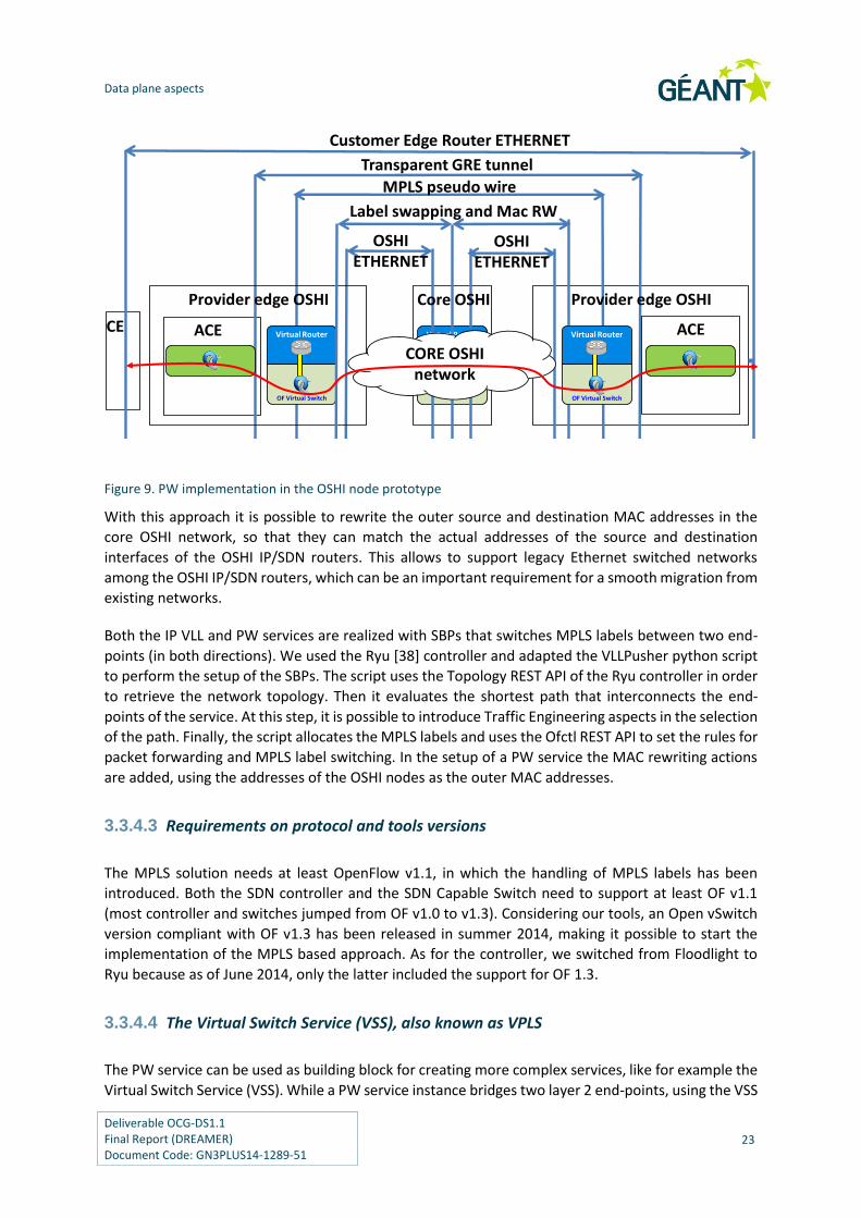
Figure 16. Mantoo enabled emulation workflow 31
Figure 17. Implementing VXLAN tunnels using Open vSwitch (OVS) 33
Figure 18. Measurement Tools in action 34
Figure 19 - CPU load vs. packet rate (plain VLAN) 35
Figure 20 – CPU load linear regression (plain VLAN) 35
Figure 21. Physical network 36
Figure 22. Overlay network 36
Figure 23. CPU Load for different tunneling mechanisms. 36
Figure 24. CPU load with VXLAN tunneling. 37
Figure 25. GOFF Physical network 38
Figure 26.GOFF Overlay network 38
Figure 27. CPU load for different OSHI services. 38
Figure 28. CPU load with limited kernel cache (10 flows) and increasing average flows. 40
Figure 29. CPU load for different number of fake flows installed in the OFCS table. 41
Figure 30 - ONOS distributed architecture 45
Figure 31 - ICONA architecture: the data plane is divided in portions interconnected
through so-called inter-cluster links (in red). Each portion is managed by multiple co-
located ONOS and ICONA instances, while different clusters are deployed in various
data centers. 46
Figure 32 - Average, maximum and minimum latency to reroute 100 paths in case of link
failure for ONOS and ICONA (2, 4 and 8 clusters) 50

Deliverable OCG-DS1.1 Final Report (DREAMER) Document Code: GN3PLUS14-1289-51
iv
Table of Tables
Table 1: Carrier Grade Network characteristics 9
Table 2: Characteristics and requirements 11
Table 3 – Average number of kernel flow entries for different traffic patterns 39
Table 4 - GÉANT network: average, maximum and minimum latency to reroute 100
paths in case of link failure for ONOS and ICONA (2, 4 and 8 clusters) 50
Table 5 - Amount of time required to obtain the network convergence after
disconnection for ONOS and ICONA 51

Deliverable OCG-DS1.1 Final Report (DREAMER) Document Code: GN3PLUS14-1289-51
1
Executive Summary
This document represents the final report of the DREAMER project, one of the beneficiary projects of
the GÉANT Open Call research initiative. Its partners are the CNIT research consortium (www.cnit.it),
the CREATE-NET research center (www.create-net.org) and the GARR consortium, the Italian NREN
(www.garr.it). The DREAMER project started in November 2013 and ended in March 2015, according
to its work plan it has produced a set of internal milestone documents describing the requirements,
the architecture and the software prototypes. The purpose of this document is to collect all the
relevant information produced by the project in a single publicly available document.
The DREAMER project had the objective of developing and exploiting Software Defined Networking
(SDN) capability in carrier grade IP backbones. DREAMER focused and produced results on how a
network based on an OpenFlow/SDN control plane can provide the same functionalities of an IP/MPLS
control plane, offering a carrier grade approach to resiliency and fault management.
The requirements for the DREAMER project have been analyzed as reported in section 2. DREAMER
considered the operational requirements coming from the GARR National Research and Education
Network (NREN) to drive the design of the solutions.
The DREAMER project had two main dimensions: scientific and experimental. The scientific dimension
considered a resilient SDN system able to smoothly operate in case of link and node failures, by
providing resiliency to the controller element and by promptly restoring paths in the data plane. The
experimental dimension implemented and validated the designed modules over the testbed facilities
provided by GÉANT.
The project developed software, performed testing and achieved results in three main areas of
OpenFlow/SDN research: data plane, control plane and experimental tools, which are respectively
dealt with in sections 3, 5 and 4.
Concerning the Data Plane (activities described in section 3), hybrid IP and SDN networking has been
considered. A solution called “OSHI” (Open Source Hybrid IP / SDN networking) has been designed
and implemented over Linux OS. An OSHI node combines traditional IP forwarding/routing (with OSPF)
and SDN forwarding implemented by means of Open vSwitch in a hybrid IP/SDN node. No open source
solutions for such a hybrid node were available before. As services to be offered to the customers,
DREAMER considered IP point to point Virtual Leased Lines (VLL), Layer 2 Pseudo Wires (PW) and Layer
2 Virtual Switches over an IP backbone. These services are implemented with virtual circuits which
have been denoted as “SBP”, for SDN Based Paths. The SBPs are established by the centralized SDN
Controllers.

Executive Summary
Deliverable OCG-DS1.1 Final Report (DREAMER) Document Code: GN3PLUS14-1289-51
2
Two approaches have been designed and implemented for the SBPs. The first approach is based on
VLAN tags, it has some limitations in terms of scalability and interoperability with legacy equipment,
but it can be implemented using OpenFlow 1.0 compliant equipment. The second approach is based
on MPLS tags, it does not suffer from scalability issues and can better interoperate with legacy
equipment, but it requires OpenFlow 1.3. The section 3 of this report provides the detailed design of
the OSHI solution, a discussion on alternative design approaches and some considerations on the
potential evolution of OpenFlow standards and equipment capability. The performance evaluation of
the implemented solutions for the data plane are reported in section 4.
The activities related to the Control Plane are described in section 5, the project exploited and
contributed to the development of the ONOS Open Source controller [2]. Thanks to an agreement
with ON.LAB (a research lab on SDN based in San Francisco), the DREAMER project partners were able
to work on the ONOS source code before it was released to the general public (which happened on
December 2014 [4]). The default ONOS features provide data plane resilience, as well as control plane
resilience for a single cluster of controllers in the same data center. The contribution of the project is
a solution to distribute the control of a geographical scale SDN network among a set of clusters of
ONOS controllers. The solution is called “ICONA” (Inter Cluster ONos Application). Section 5 includes
the results of experimental tests aimed at comparing ICONA with a standard ONOS setup, and
evaluating the performance of the two solutions in an emulated environment.
As for the experimental tools (see section 4), DREAMER has developed and released Mantoo
(Management tools) that provides an easy design, deployment and control of the SDN experiments.
It Includes a web front end called “Topology 3D” (Topology Designer, Deployer & Director) that allows
to graphically design a network topology (made of L3 routers, L2 switches, end devices) and to
configure the set of services to be provided on top. Then the topology can be automatically deployed
as an overlay network over a distributed testbed (e.g. the GÉANT testbed) or within a Mininet
emulator. Finally, the web front end allows to access the shell interface on each node of the deployed
topology. The Mantoo experimental tools have been used to gather performance measurements of
some aspects related to the data plane (OSHI) solution as described in sections 4.2.
DREAMER has implemented prototypes of the proposed solutions based on Open Source tools and
has contributed to the development of some of these tools (the details about software installation
and use are reported in appendix). The software developed by the DREAMER project has been
released as Open Source, under the terms of the Apache 2.0 license. Therefore DREAMER is having an
impact towards the availability of a truly open ecosystem for carrier grade backbone IP networks
based on the SDN paradigm. DREAMER has produced results than are available and can be used by
the NRENs and the GÉANT backbone when planning future upgrades. The software has been released
as Open source.

Deliverable OCG-DS1.1 Final Report (DREAMER) Document Code: GN3PLUS14-1289-51
3
1 Introduction
Software Defined Networking (SDN) [12] is proposed as the new paradigm for networking that may
drastically change the way IP networks are run today. Important applications have been found in Data
Centers and in corporate/campus scenarios and there have been several proposals considering SDN
applicability in wide area IP networks of large providers. Considering the wide area IP networks use-
case, critical open issues are:
(i) how to provide the scalability and fault tolerance required in operators’ environments;
(ii) how to cope with the high latency in the control plane (due to a geographically distributed
deployment).
More generally, the scientific and technological question “what is the best approach to introduce SDN
in large-scale IP Service Providers (ISP) networks?” is definitely still open and different solutions have
been proposed, A complete and definitive answer to this question needs to consider data plane and
control plane aspects.
The OSHI (Open Source Hybrid IP/SDN) networking architecture, addresses the above question from
the point of view of data plane. The DREAMER project has designed the OSHI and provided an Open
Source reference implementation complemented with a set of services (IP Virtual Leased Lines,
Ethernet Pseudo-Wirese and Virtual Switches, that will be described in section 3) and a set of
management tools for performing experiments (described in section 4).
As for the control plane, its reliability, scalability and availability were among the major concerns
expressed by Service and Cloud Providers since the beginning of the Software Defined Networking
(SDN) revolution. Existing deployments show that standard IP/MPLS networks natively offer fast
recovery in case of failures. Their main limitation lies in the complexity of the distributed control plane,
implemented in the forwarding devices. IP/MPLS networks fall short when it comes to design and
implementation of new services that require changes to the distributed control protocols and service
logic. The SDN architecture, that splits data and control planes, simplifies the introduction of new
services, moving the intelligence from the physical devices to a Network Operating System (NOS), also
known as controller, that is in charge of all the forwarding decisions. As the NOS cannot introduce a
single point of failure in production environments, it is usually considered logically centralized. In
practical terms, it needs to be replicated to provide the required resiliency. The DREAMER project
starts from the resiliency solution provided by the ONOS controller, which implements a cluster of
controllers. This solutions works well when the cluster of controllers resides in a single data center
and it is not able to properly synchronize remote controller instances. The proposed ICONA (Inter

Introduction
Deliverable OCG-DS1.1 Final Report (DREAMER) Document Code: GN3PLUS14-1289-51
4
Cluster ONos Application) solution considers a set of clusters of ONOS controllers. The controllers in
each cluster are in the same data center, but the different clusters are geographically distributed.
The main contributions of DREAMER are listed hereafter. Items 1 to 3 are related to data plane aspects
of SDN integration in ISP networks. Items 4 and 5 concern the emulation platform and its management
tools. Item 6 is about performance assessment.
1. Design of a hybrid IP/SDN architecture called Open Source Hybrid IP/SDN (OSHI).
2. Design and implementation of an OSHI node made of Open Source components.
3. Analysis of extensions to the OpenFlow protocol and to hardware/software switches to
optimize the support the proposed architecture.
4. Design and implementation of the ICONA (Inter Cluster ONos Application) solution to control
a large scale geographical network with a set of clusters of ONOS controllers.
5. Design and implementation of an open reference environment to deploy and test the OSHI
framework and the services developed on top of it.
6. Design and implementation of a set of management tools for the emulation platforms, called
Mantoo.
7. Evaluation of some performance aspects of the proposed architecture and its implementation.
The source code of all the components of the prototypes developed by DREAMER is freely available
at [26] (OSHI and Mantoo) and [52] (ICONA). In order to ease the initial environment setup, several
components have also been packaged in a ready-to-go virtual machine, with pre-designed example
topologies up to 60 nodes. To the best of our knowledge, there is no such hybrid IP/SDN node available
as Open Source software, nor such an emulation platform with a comprehensive set of management
tools.

Deliverable OCG-DS1.1 Final Report (DREAMER) Document Code: GN3PLUS14-1289-51
5
2 Requirement analysis: Carrier Grade Requirements and Research and Education Networks
The objective of the DREAMER proposal is to investigate and prototype how a network based on the
OpenFlow/SDN control plane can provide the same functionalities of an IP/MPLS control plane,
offering a “carrier grade” approach to resiliency and fault management.
Most NRENs and the GÉANT backbone introduced the MPLS protocol in the operation of their IP-based
networks. The main functionalities considered are the possibility to do traffic engineering and the
creation of virtual circuits, including at Layer 2 to provide VPN services.
The NRENs and GÉANT networks are largely over provisioned and Traffic engineering is seldom used.
The request for VPNs has instead constantly increased during the last years. Multi Domain VPNs are
particularly suited to the large number of Research and Education domains and projects in Europe. A
MD-VPN service has been recently brought into service [5]. For this reason the Traffic Engineering
aspects will be taken into account with lower priority in the DREAMER project. The designed
architecture will offer the capability of doing traffic engineering, but the design and implementation
of specific algorithms and solution will be out of the scope of the DREAMER project.
The SDN paradigm and the OpenFlow protocol may provide a simplification in control plane and their
main advantage lies in the flexibility and “openness” of the approach: adding a new service or feature
can be a matter of software engineering, and may not be limited to protocols/capabilities of the
existing hardware; vendor lock-in issues could be avoided or reduced.
This section of the document elaborates on the carrier grade requirements for NREN networks and
considers their implication for an SDN/OpenFlow implementation to side and eventually replace the
MPLS technology in the NRENs and GÉANT networks.
2.1 The NRENs and the GÉANT networks
Research and education networking in Europe is organised in a hierarchical fashion, connecting
research and education community users. The network connection between two end users will be
provided by a chain of several networks, each connected to the next. This chain will typically start with

Requirement analysis: Carrier Grade Requirements and Research and Education Networks
Deliverable OCG-DS1.1 Final Report (DREAMER) Document Code: GN3PLUS14-1289-51
6
a campus network, then may include a regional network before connecting to a national (NREN)
network. Then to the pan-European backbone GÉANT, from there to another NREN and so on back
down the chain to the user at the other end. Most of international connectivity is provided through
GÉANT. Connectivity to General Internet is often local to each country, only some NRENs use the
GÉANT DWS service to access Internet providers.
The networks are used by tens of millions of users for all purposes and are required to perform to high
quality standards for reliability and performance.
2.1.1 GÉANT
The GÉANT [1] network topology is shown in Figure1. The topology is based on a large core of leased dark
fibers and a set of circuits. The physical topology has been carefully chosen to avoid or minimize any shared
path between fibers. The optical data plane is based on INFINERA equipment, with up to 100 Gbps for each
wavelength and a maximum of 500Gbps for each direction in an optical node. The switching equipment is
based on Juniper equipment.
The offered network service include to provide point to point circuits at all layers, including optics and
IP/MPLS.
GÉANT Plus is delivered over the highly resilient IP network and, as such, offers extremely high
availability:
99.999% in the core backbone
99.4% (across GÉANT, including client interfaces).
For an unprotected lambda, the availability target is 99.5% up to 1000km, which is then reduced by
0.5% for every additional 1000km.

Requirement analysis: Carrier Grade Requirements and Research and Education Networks
Deliverable OCG-DS1.1 Final Report (DREAMER) Document Code: GN3PLUS14-1289-51
7
Figure1: GÉANT network topology [6]
2.1.2 GARR-X
GARR-X is the latest generation of the GARR network infrastructure (Figure 2). It is based on direct
control of all its components, from its 8500 Km of fiber to application level systems. The GARR-X
network seamlessly peers and it is integrated with regional or metropolitan networks to provide an
end to end services to all its users.

Requirement analysis: Carrier Grade Requirements and Research and Education Networks
Deliverable OCG-DS1.1 Final Report (DREAMER) Document Code: GN3PLUS14-1289-51
8
Figure 2: GARR-X fiber topology
On top of the fiber topology the GARR-X network features a highly reliable and robust IP network. Its
availability is similar to the GÉANT:
99.99% in the core backbone
99.84% (including client interfaces).

Requirement analysis: Carrier Grade Requirements and Research and Education Networks
Deliverable OCG-DS1.1 Final Report (DREAMER) Document Code: GN3PLUS14-1289-51
9
2.2 Carrier Grade requirements
The term "carrier grade" is used in telecommunication and computing to denote a system that is
extremely reliable and with stable performances and functionalities [9].
Large communication networks provide essential services to the community, which are expected to
be always available and therefore networks have to exhibit “carrier grade” characteristics. The
network is itself a complex system made from different active and passive components arranged in a
physical topology. The Table 1 summarizes the key characteristics required by the system as a whole
and by its components to various degree. It is a summary of requirements in literature [7], [8] and
reference therein.
Table 1: Carrier Grade Network characteristics
Characteristic Description
Reliability Low failure rates to minimize maintenance and inventory
costs. High availability, including live upgrades.
Fault-tolerant architecture is here
considered a subset of Reliability
The architectural aspect refers to the type of redundancy—
both internal redundancy and inter-element or network-
level redundancy. The system has to behave with none or
minor degradation under known/random faults and
recover in a short period of time
Robustness and security features Required to avoid and/or mitigate the impact of intrusion
or denial of services (DoS) attacks, traffic overloads, and
human error.
Scalability Support a variety of equipment and services, capacities up
to 100 Gbps, operate up to thousands of equipment.
Operate in a wide range of network latencies,
Management features to support
operational measurement and
tracking, performance and alarm
monitoring, and fault diagnostics
Effective monitoring of failures and system performance. It
provides operators with data for proactive network
planning and pre- and post-failure data for causal analysis
to drive corrective and preventive actions.
Maintainability is here considered a
subset of Reliability
fast provisioning, fault tracking, performance
measurement
Quality of Service is here considered a
quantification of above
characteristics implementation
More a service definition of SLA supported by the
characteristics in this table. The availability and quality of
packet transmissions (packet losses, delay variation and
errors), also known as “number of ‘9’”, places more
stringent requirements for carrier grade characteristics

Requirement analysis: Carrier Grade Requirements and Research and Education Networks
Deliverable OCG-DS1.1 Final Report (DREAMER) Document Code: GN3PLUS14-1289-51
10
Resiliency (see picture below) Resiliency is not consider an elementary characteristic, but
rather the intersection of reliability and security. The choice
in dreamer is in line with the definition of the word as “the
ability of a substance or object to spring back into shape;
elasticity” and “the capacity to recover quickly from
difficulties”.
ReliabilitySecurity .
RobustnessResiliency
Figure 3: Resiliency as a secondary characteristics
The implementation of Carrier Grade characteristics involves every component of the system and its
architecture. In case of networking every layer has to be carefully engineered.
In the NRENs networks the fiber and leased circuit topology is chosen to obtain physical path resiliency
in case of failures and avoid physical partitioning also in the case of multiple failures in the core. The
optical equipment and the switching equipment are also redundant in their components and in the
physical positions.
2.3 DREAMER Requirements
The objective of DREAMER is “to investigate how a network based on an OpenFlow/SDN control plane
can provide the same functionalities of an IP/MPLS control plane, offering a carrier grade approach to
resiliency and fault management.”
This restrict the focus of the project to the control plane (and virtual data planes created), considering
software running on computing elements. The project will take the following assumptions:
The physical network has been engineered to be carrier grade, as defined above, in its
components: fibers/circuit, topology, hardware in routers and switches
The computing elements’ hardware and the operating systems used are carrier grade (e.g. [10])
Usual control and data plane IP is present in all network nodes, including DREAMER own
control plane (e.g. based on OSPF, BGP)

Requirement analysis: Carrier Grade Requirements and Research and Education Networks
Deliverable OCG-DS1.1 Final Report (DREAMER) Document Code: GN3PLUS14-1289-51
11
IP/MPLS service targeted are VPN (high priority for DREAMER) and traffic engineering (lower
priority for DREAMER).
The DREAMER architecture requirements can be derived from the MPLS functionalities to be replaced
and from Table 1 characteristics, quantified according to the GARR and GÉANT network current
performance metrics.
In considering the DREAMER objectives, the carrier grade requirements will consider that the physical
components of the network have been engineered to be carrier grade. Also computing system are
supposed to be carrier grade, see for Linux the specification of carrier grade Linux [10]. The control
plane functionalities and the DREAMER behavior will be engineered and tested to verify their grade.
The MPLS functionalities that DREAMER has to provide, with carrier grade characteristics are:
virtual point to point circuit creation at layer 2 (emulation of Ethernet circuits), with and
without automatic resiliency
a VPN functionality similar to the one that can be created with MPLS (the BGP/MPLS solution
uses BGP to distribute VPN routing information across the provider's backbone and MPLS to
forward VPN traffic from one VPN site to another)
traffic engineering of flows (implementation of specific algorithms is out of scope for
DREAMER project)
Given the multi-domain nature of the European NREN and the need to provide virtual private
networks that span more than one NREN, the DREAMER architecture and functionalities it should be
possible to extend it toward multi-domain stitching of virtual circuit at layer 2 and at layer 3, either
manually or automatically.
Table 2: Characteristics and requirements
Reliability The software components and the architecture should
ensure that the system can remain active for a very long
period of time, without interruption.
Fault-tolerant architecture The DREAMER architecture should be capable of
graciously handling the various type of failures, mostly in
software. It should also react to physical substrate
failures, e.g. redirecting traffic to different paths.
Robustness and security features The DREAMER active components and the protocols used
to communicate should react properly to attacks and
protect information, using encryption, authentication and
authorization e.g.
Characteristic DREAMER requirement

Requirement analysis: Carrier Grade Requirements and Research and Education Networks
Deliverable OCG-DS1.1 Final Report (DREAMER) Document Code: GN3PLUS14-1289-51
12
Scalability Support a variety of equipment and services, capacities up
to 100 Gbps, operate up to thousands of equipment.
Operate in a wide range of network latencies, preserving
fast resilience
Management features to support
operational measurement and
tracking, performance and alarm
monitoring, and fault diagnostics
The dreamer components should include monitoring
functionalities for the system and the traffic.
Maintainability The system should be modular and upgradable with minor
downtime.
Two architectural aspects, will be specifically targeted:
i) the control plane controller resilience and its distribution;
ii) the data plane resilience, with carrier grade fast restoration mechanism.
The target performance is to offer availability values in the same range of GÉANT and GARR-X
networks.
In addition to availability, the architecture should also keep at minimum the packet loss in case of
circuit or node failures. The capacity to consider are between 10 Gbps and 100 Gbps, which
correspond to about one to twelve MB for each millisecond. A typical router buffer of 2 GB is capable
of storing between 2 and 100 millisecond of traffic in case of routing issues, in case of circuits longer
than 1 millisecond the buffering time is correspondently reduced. A target convergence time of tens
of milliseconds is desirable.

Deliverable OCG-DS1.1 Final Report (DREAMER) Document Code: GN3PLUS14-1289-51
13
3 Data plane aspects
This section deals with data plane aspects, reporting on the design of the proposed hybrid IP/SDN
networking solution (OSHI). In section 3.1 we discuss some issues related to the introduction of SDN
in IP Service Providers networks and describe the state of the art of similar solutions; in section 3.2 we
define the main concepts of the proposed hybrid IP/SDN networking architecture; section 3.3 provides
the detailed description of the proposed design, the notion of “SDN Based Paths” (SBP) is provided
and the two implemented solutions using VLAN tags or MPLS labels to guarantee the coexistence
among regular IP and SDN traffic implementing the so called are respectively described in section
3.3.3 and 3.3.4; in section 6.1 we show some limitations of current SDN ecosystem and propose the
needed extensions. The performance evaluation of some aspects of the proposed OSHI solution will
be reported in the section 4 later on, after the discussion of the experimental tools.
3.1 SDN Applicability in IP Providers Networks
SDN is based on the separation of the network control and forwarding planes. An external SDN
controller can (dynamically) inject rules in SDN capable nodes. According to these rules the SDN nodes
perform packet inspection, manipulation and forwarding, operating on packet headers at different
levels of the protocol stack.
We focus on SDN applicability in IP Service Providers networks. Figure 4 shows a reference scenario,
with a single IP provider interconnected with other providers using the BGP routing protocol. Within
the provider network, an intra-domain routing protocol like OSPF is used. The provider offers Internet
access to its customers, as well as other transport services (e.g. layer 2 connectivity services or more
in general VPNs). Using the terminology borrowed by IP/MPLS networks, the provider network
includes a set of Core Routers (CR) and Provider Edge (PE) routers, interconnected by point to point
links (Packet Over Sonet, GigaBit Ethernet, 10GBE…) or by legacy switched LANs (and VLANs). The
Customer Edge (CE) routers is the node in the customer network connected to the provider network.
Most often, an ISP integrates IP and MPLS technologies in its backbone. MPLS creates tunnels (LSP –
Label Switched Path) among routers. On one hand, this can be used to improve the forwarding of
regular IP traffic providing:
i) traffic engineering
ii) fault protection
iii) no need to distribute of the full BGP routing table to intra-domain transit routers.

Data plane aspects
Deliverable OCG-DS1.1 Final Report (DREAMER) Document Code: GN3PLUS14-1289-51
14
On the other hand, MPLS tunnels are used to offer VPNs and layer 2 connectivity services to customers.
In any case, the commercial MPLS implementations are based on traditional (vendor-locked) control
plane architectures that do not leave space for introducing innovation in an open manner. As a matter
of fact, in case of complex services involving the MPLS control plane, IP Service Providers rely on single-
vendor solutions. The management of large-scale IP/MPLS network is typically based on proprietary
(and expensive) management tools, which again constitute a barrier to the innovation.
PE – Provider Edge Router
CR - CoreRouter
L2 – Layer 2Switch
CR
CRCR CR
CR
PE
PE
PE
PEs
Peering withother providers
Peering with otherproviders
CE – Customer Edge Router
PEs
PEs
L2
L2
CE
CE
CE
CEs
CEs CEs
CEs
CE
CE
Figure 4. Reference scenario: an IP provider network
Let us consider the migration of a Service Provider network, based on IP/MPLS, to SDN. CR and PE
routers could be replaced by SDN capable switches, giving the ability to realize advanced and
innovative services and/or to optimize the provisioning of existing ones. The migration paths should
foresee the coexistence of IP and SDN based services, in a hybrid IP/SDN scenario (resembling the
current coexistence of IP and MPLS). According to the taxonomy defined by Vissicchio et al [14], this
approach can be classified as Service-Based Hybrid SDN or Class-Based Hybrid SDN, depending on the
portion of the traffic controlled: classes of traffic or different type of services. In this migration
scenario a set of hybrid IP/SDN nodes are capable of acting as plain IP routers (running the legacy IP
routing protocols), as well as SDN capable nodes, under the control of SDN controllers. We observe
that IP/MPLS control and forwarding plane have been optimized in the years and are capable to
operate on large-scale carrier networks, while SDN technology has not reached the same maturity
level. Therefore, the advantage of introducing SDN technology in a carrier grade IP backbone is not
related to performance improvements. Rather we believe that the openness of the SDN approach
eliminates the need of complex distributed control planes architectures with closed implementations
and difficult interoperability, facilitates the development of new services and fosters innovation.
3.1.1 State of the art
Pure SDN solutions based on L2 switches inter-connected with a centralized controller have been
demonstrated both in data-centers and in geographically distributed research networks, such as
OFELIA [20] in EU, GENI [21] and Internet2 [22][23] in US. To the best of our knowledge, these solutions
do not integrate L3 routing among the SDN capable L2 switches. We argue that an ISP network

Data plane aspects
Deliverable OCG-DS1.1 Final Report (DREAMER) Document Code: GN3PLUS14-1289-51
15
requires a more sophisticated approach that integrates IP routing protocols and can natively interwork
with legacy IP routers. As stated in [14], a hybrid SDN model that combines SDN and traditional
architectures may “sum their benefits while mitigating their respective challenges”. The recent
literature presents some preliminary architectures toward hybrid IP/SDN networks. An example of a
solution that tries to integrate also L3 routing and SDN is reported in [24].
RouteFlow [17] creates a simulated network, copy of the physical one, in the SDN controller, and uses
distributed routing protocols, such as OSPF, BGP, IS-IS between the virtual routers inside the emulated
network. A traditional IP routing engine (Quagga) computes the routing tables that are eventually
installed into the hardware switches via the OF protocol.
In [16] the authors present an Open Source Label Switching Router that generates OSPF and LDP
packets using Quagga [30]. The node computes the MPLS labels that are then installed in the switches
using the OpenFlow (OF) protocol. This architecture provides a distributed “standard” control plane,
while it uses OF only locally in a node to synchronize the FIBs and to program the data plane.
The Google B4 WAN [19] can be considered as an integrated hybrid SDN solution, and it has likely been
the first application of the SDN approach to a large-scale WAN scenario. However in this use case the
intra-domain routing protocol uses SDN as an interface to the forwarding plane. The B4 solution takes
into account the WAN which interconnects the Google’s datacenter, we believe that this use case is
rather different from traditional ISP scenario. To give an example, administrative problems are not
addressed in a single administrative domain. The RouteFlow hybridization is quite similar to the one
designed for Google’s B4 solution.
Compared with these works, our solution considers hybrid IP/SDN nodes also capable of dealing with
IP routing, thus achieving easier interoperability with non-OF devices in the core network and fault-
tolerance based on standard IP routing. The idea of supporting retro-compatibility and incremental
deployment of SDN is not new. According to the OF specifications [18], two types of devices are
considered: OF-only and OF-hybrid which can support both OF processing and standard L2/L3
functionalities. Currently, only proprietary hardware switches implement the hybrid approach offering
also L3 standard routing capabilities; in our work we analyzed and implemented a fully Open Source
OF-hybrid solution designed to be flexible and scalable, so as to facilitate experimentation on hybrid
IP/SDN networks at large scale.
3.2 Proposed Hybrid IP/SDN Architecture
In the IP/MPLS architecture there is a clear notion of the MPLS tunnels, called Label Switched Paths
(LSPs). In an SDN network several types of tunnels or more generically network paths can be created,
leveraging on the ability of SDN capable nodes to classify traffic based on various fields such as MAC
or IP addresses, VLAN tags, MPLS labels. As there is not a standard established terminology for such
concept, we will refer to these paths as SDN Based Paths (SBP). An SBP is a “virtual circuit” setup using
SDN technology to forward a specific packet flow between two end-points across a set of SDN capable
nodes. The notion of packet flow is very broad and it can range from a micro-flow i.e. a specific TCP
connection between two hosts, to a macro-flow e.g. all the traffic directed towards a given IP subnet.
As highlighted before, a flow can be classified looking at headers at different protocol levels.

Data plane aspects
Deliverable OCG-DS1.1 Final Report (DREAMER) Document Code: GN3PLUS14-1289-51
16
We address the definition of the hybrid IP/SDN network by considering:
i) mechanisms for coexistence of regular IP traffic and SBPs
ii) the set of services that can be offered using the SBPs;
iii) ingress traffic classification and tunneling mechanisms.
Let us consider the coexistence of regular IP traffic and SBPs on the links between hybrid IP/SDN nodes.
An SDN approach offers a great flexibility and can classify packets with a “cross-layer” approach, by
considering packet headers at different protocol levels (MPLS, VLANs, Q-in-Q, Mac-in-Mac and so on).
Therefore it is possible to specify a set of conditions to differentiate the packets to be delivered to the
IP forwarding engine from the ones that belong to SBPs. In general, these conditions can refer to
different protocol headers, can be in the form of white- or black- lists and can change dynamically,
interface by interface. This flexibility may turn into high complexity, therefore the risk of
misconfigurations and routing errors should be properly taken into account (see [11]). Without
preventing the possibility to operate additional coexistence and tunneling mechanisms in a hybrid
IP/SDN network, we propose MPLS tagging as the preferred choice and VLAN tagging as a sub-optimal
choice. Both solutions have been implemented in our platform.
Let us now consider the services and features that can be offered by the hybrid IP/SDN network. As
primary requirements we assume three main services/functionalities:
(i) virtual private networks (Layer 2 and Layer 3),
(ii) traffic engineering
(iii) fast restoration mechanisms.
Moreover the architecture should facilitate the realization of new services or the development of new
forwarding paradigms (for example Segment Routing [33]) without the introduction of complex and
proprietary control planes.
As for the traffic classification, the ingress PEs need to classify incoming packets and decide if they
need to be forwarded using regular IP routing or they belong to the SBPs. The egress edge router will
extract the traffic from the SBPs and forward it to the appropriate destination. We considered (and
implemented in our platform) two approaches for the ingress classification: i) classification based on
physical access port; ii) classification based on VLAN tags. As the ingress classification is not a specific
feature of our architecture, we did not consider other traffic classification, e.g. based on MAC or IP
source/destination addresses. However these approaches can be easily implemented without
changing the other components.
Finally, we considered a VLAN based tunneling mechanisms and two MPLS based tunneling
mechanisms: plain IP over MPLS ([34], here referred to as IPoMPLS) and Ethernet over MPLS (EoMPLS,
described in RFC 3985 [35]). Different services are supported by these tunneling mechanisms: the
IPoMPLS and the VLAN based tunneling only support the relay of IP and ARP packets between two IP
end points. We refer to this service as IP Virtual Leased Line (IP VLL). The EoMPLS tunneling mechanism
can support the relaying of arbitrary layer 2 packets, providing the so called Pseudo-Wire (PW) service.

Data plane aspects
Deliverable OCG-DS1.1 Final Report (DREAMER) Document Code: GN3PLUS14-1289-51
17
3.3 Detailed Design of the Hybrid IP/SDN Solution
In this section we present the detailed design and the implementation of the proposed architecture.
We describe the Open Source tools that we have integrated and how their practical limitations have
been taken into account to deliver a working prototype. We will first introduce the high level
architecture of an OSHI node (3.3.1) and the basic services we provide (IP Virtual Leased Line and
Pseudo-wires, 3.3.2). Then we describe the two different options of using VLAN tags or MPLS labels to
realize SDN Based Paths (SBPs) and to support the coexistence between IP based forwarding and SBP
forwarding. As we will show, the design of MPLS based option has been more challenging and the
resulting implementation is more complex. In part this is due to inherent limitation of OpenFlow
architecture, in part to the shortcomings of the Open Source tools that we have integrated. In part
due to the fact that MPLS over Ethernet is not clarified because usually MPLS over PPP is used.
3.3.1 OSHI High Level Node Architecture
We designed our Open Source Hybrid IP/SDN (OSHI) node combining an OpenFlow Capable Switch
(OFCS), an IP forwarding engine and an IP routing daemon. The OpenFlow Capable Switch is connected
to the set of physical network interfaces belonging to the integrated IP/SDN network, while the IP
forwarding engine is connected to a set of OFCS virtual ports, as shown in Figure 5. In our OSHI node,
the OFCS component is implemented using Open vSwitch (OVS) [29], the IP forwarding engine is the
Linux kernel IP networking and Quagga [30] acts as the routing daemon.
Virtual ports
Physical interfaces
IP Forwarding Engine – IP FE(Linux networking)
IP Routing Daemon(Quagga)
IP
SDNOF Capable Switch - OFCS
(Open vSwitch)
LocalManagementEntity (LME)
Figure 5. OSHI Hybrid IP/SDN node architecture
The internal virtual ports that interconnect the OFCS with the IP forwarding engine are realized using
the “Virtual Port” feature offered by Open vSwitch. Each virtual port is connected to a physical port of
the IP/SDN network, so that the IP routing engine can reason in term of the virtual ports, ignoring the
physical ones. The OFCS differentiates among regular IP packets and packets belonging to SDN Based
Paths. By default, it forwards the regular IP packets from the physical ports to the virtual ports, so that
they can be processed by the IP forwarding engine, controlled by the IP routing daemon. This approach
avoids the need of translating the IP routing table into SDN rules to be pushed in the OFCS table. A

Data plane aspects
Deliverable OCG-DS1.1 Final Report (DREAMER) Document Code: GN3PLUS14-1289-51
18
small performance degradation is introduced because a packet to be forwarded at IP level will cross
the OFCS switch twice. It is possible to extend our implementation to consider mirroring of the IP
routing table into the OFCS table, but this is left for future work.
An initial configuration of the OFCS tables is needed to connect the physical interfaces and the virtual
interfaces, to support the OFCS-to-SDN-controller communication, or for specific SDN procedures (for
example to perform Layer 2 topology discovery in the SDN controller). A Local Management Entity
(LME) in the OSHI node takes care of these tasks. In our setup, it is possible to use an “in-band”
approach for OFCS-to-SDN-controller communication, i.e. using the regular IP routing/forwarding and
avoiding the need of a separate out-of-band network. Further details and the block diagram of the
control plane architecture of OSHI nodes are reported in [27].
3.3.2 OSHI basic services: IP VLL and PW
We designed and implemented two basic services to be offered by the hybrid IP/SDN networks: the
IP “Virtual Leased Line” (IP VLL) and the Layer 2 “Pseudo-wire” (PW) see Figure 6. Both services are
offered between end-points in Provider Edge routers, the end-points can be a physical or logical port
(i.e. a VLAN on a physical port) of the PE router connected to a Customer Edge (CE). The
interconnection is realized in the core hybrid IP/SDN network with an SBP using VLAN tags or MPLS
labels.
Figure 6. IP VLL and PW services
The IP VLL service guarantees to the IP end-points to be directly interconnected as if they were in the
same Ethernet LAN and sending each other IP and ARP packets. It is not meant to allows the served
SBP end-points to send packets with arbitrary Ethertype (e.g. including VLAN packets). We

Data plane aspects
Deliverable OCG-DS1.1 Final Report (DREAMER) Document Code: GN3PLUS14-1289-51
19
implemented the IP VLL service both using VLAN tags and MPLS tags. In both cases the original source
and destination MAC addresses, shown as “C” (for Customer) in the headers of the packets in Figure
6, are preserved in the transit in the network core. This may cause problems if legacy L2 switches are
used to interconnect OSHI nodes, therefore our implementation of IP VLL service can only work if all
edge and core nodes are OSHI capable connected to each other without legacy intermediate switches
in between. In principle one could implement MAC address rewriting replacing the customer
addresses them with the addresses of the ingress and egress PEs or on a hop-by-hop case. This is
rather complex to realize and to manage, because the egress node should restore the original
addresses, needing state information per each SBP, so we did not follow this option.
The PW service is also known as “Pseudowire Emulation Edge to Edge” (PWE3), described in RFC 3985
[35]. The PW service provides a fully transparent cable replacement service: the endpoints can send
packets with arbitrary Ethertype (e.g including VLAN, Q-in-Q). We implemented the PW service only
using the MPLS tags, the customer Ethernet packet is tunneled into an MPLS packet as shown in Figure
6. This approach solves the interworking issues with legacy L2 networks related to customer MAC
addresses exposure in the core.
3.3.3 OSHI - VLAN based approach
3.3.3.1 Coexistence mechanisms
Two coexistence mechanisms have been designed:
i) Tagged coexistence, in which the IP traffic is transported with a specific VLAN tag while
SBPs use other VLAN tags;
ii) Untagged coexistence, in which the IP traffic travels “untagged” and SBPs use VLAN tags.
Both mechanisms can interwork with existing legacy VLANs, as long as a set of tags is reserved for our
use on each physical subnet/link (and this is needed only if the link between two routers already runs
on a VLAN). As for the implementation of coexistence mechanisms we used the multiple tables
functionality. It has been introduced with OF v1.1, but it is possible to emulate it using OF v1.0 with
the so called “Nicira extensions”. We have initially leveraged the Nicira extensions implementation in
Open vSwitch and then migrated to standard multiple tables when their support has been included in
Open vSwitch. For Untagged coexistence, incoming untagged traffic will be directed to a virtual port
(toward the IP forwarding engine), incoming tagged traffic will be directed to a physical port according
to the configuration of the SBPs (VLAN tag can be switched appropriately). For Tagged coexistence,
incoming traffic tagged with the specific VLAN tag for regular IP traffic will be directed to a virtual port
(toward the IP forwarding engine), while traffic tagged with the other VLAN tags will be directed to a
physical port according to the configuration of the SBPs (VLAN tag can be switched appropriately). The
details are also reported in [27].
3.3.3.2 Ingress classification and tunneling mechanisms
As for the ingress classification functionality in a Provider Edge router, we use the input port to classify
untagged traffic as regular IP traffic or as belonging to the end-point of a VLL. For VLAN tagged traffic
entering in a physical port of a PE router, each VLAN tag can individually mapped to a VLL end point
Data plane aspects
Deliverable OCG-DS1.1 Final Report (DREAMER) Document Code: GN3PLUS14-1289-51
20
or assigned to regular IP traffic. For the untagged traffic, the implementation of the ingress
classification is realized within the OFCS of the OSHI Provider Edge nodes. By configuring rules in the
OFCS, it is possible to map the untagged traffic on an ingress physical port to a virtual port (for regular
IP) or to an SBP (for a VLL end-point). For the tagged traffic, the incoming classification relies on the
VLAN handling of the Linux networking: each VLAN tag x can be mapped to a virtual interface eth0.x
that will simply appear as an additional physical port of the OFCS.
The IP VLL service is realized with an SBP that switches VLAN tags between two end-points (in both
directions). This has a severe scalability issues as the number of SBPs on a link is limited to 4096.
Moreover in case legacy VLAN services are implemented on the links among the OSHI nodes, the VLAN
label space needs to be partitioned between the SBPs and the legacy VLAN services, complicating the
management and reducing the maximum number of SBPs on a link.
We have implemented the IP VLL service in the VLAN based approach on top of the Floodlight
controller [28]. In particular, the SBPs are setup using a python script called VLLPusher. It uses the
Topology REST API of the Floodlight controller in order to retrieve the route that interconnects the
VLL end-points. In this approach the route is chosen by the Floodlight controller (currently it simply
selects the shortest path). The implementation of traffic engineering mechanisms for the VLLs would
require to modify the route selection logic within the Floodlight controller. The script allocates the
VLAN tags and then uses the Static Flow Pusher REST API of Floodlight in order to set the rules for
packet forwarding and VLAN tag switching.
3.3.3.3 Requirements on protocol and tools versions
The proposed implementation of the VLAN based approach only requires OpenFlow 1.0 compliance
in the controller. On the OFCS side, it requires the support for multiple tables which has been
introduce in OF 1.1 and can be emulated using the proprietary Nicira extensions. In fact, the Local
Management Entity uses the multiple table features for the initial configuration of the OFCS, while the
run-time rules injected by the controller use OF v1.0. In our first implementation we relied on the
Nicira extensions implemented in Open vSwitch, hence we were able to release a working prototype
of a hybrid IP/SDN network using Open Source components in May 2014.
3.3.4 OSHI - MPLS based approach
In this subsection we illustrate the MPLS based approach. With respect to the VLAN based solution, it
extends the functionality and the services offered by the OSHI networks. It solves the scalability issue
(in terms of number of SBPs that can be supported on each link) of the VLAN solution. The use of MPLS
labels enables the establishment of up to 220 (more than 106) SBPs on each link. We have implemented
both IP VLL and PW services with MPLS, in both cases the MPLS solution does not interfere with VLANs
that can potentially be used in the links between OSHI nodes.
3.3.4.1 Coexistence mechanisms
For the coexistence of regular IP service (best effort traffic) and SDN services (using SDN Based Paths)
we use the Ethertype field of the L2 protocol. This corresponds to one of the mechanisms that can be

Data plane aspects
Deliverable OCG-DS1.1 Final Report (DREAMER) Document Code: GN3PLUS14-1289-51
21
used in the IP/MPLS model: regular IP traffic is carried with IP Ethertype (0x0800), SBPs are carried
with MPLS Ethertypes (0x8847 and 0x8848). We have implemented the coexistence solution using the
OpenFlow multi-table functionality, as shown in Figure 7. Table 0 is used for regular IP, ARP, LLDP,
BLDP, etc..., table 1 for the SBPs. In particular, Table 0 contains:
i) two rules that forward the traffic with the Ethertypes 0x8847 (MPLS) and 0x8848
(Multicast MPLS) to Table 1;
ii) the set of rules that “bridge” the physical interfaces with Virtual Interfaces and vice versa;
iii) two rules that forward the LLDP and BLDP traffic to the controller.
Table 1 contains the set of rules that forward the packets of the SBPs according to the associated IP
VLL or PW service. The coexistence in Table 0 is assured through different levels of priority. As regards
the rule associated to the Multicast MPLS Ethertype, it is used for the VLL service (more below), while
the PW service would need only the rule matching the unicast MPLS Ethertype.
Packet IN start at table 0
Match in table 0 ?
Send to controller
GOTO table 1
Execution action set
Match in table 1 ?
MATCH1, action1MATCH2, action2MATCH3, action3MATCH4, action4
Execution action set
....
MPLSM, goto:1INPORT=1, output:2
INPORT=3, output:4
MPLS, goto:1MPLSM, goto:1
INPORT=1, output:2
IP, ARP, ...
SBPs RyuLME
Figure 7. Packet processing in the OFCS flow tables
3.3.4.2 Ingress classification and tunneling mechanisms
As regards the ingress classification, the same mechanisms described for the VLAN approach are
reused: the classification can be based on the physical input port or on the incoming VLAN.
Let us analyze the tunneling mechanisms in the OSHI MPLS approach. Figure 8 shows the tunneling
realized by OSHI-PE for the IP VLL service in the left half. C stands for Customer, Ingr refers to the
ingress direction from customer to core, Egr refers to the opposite direction (egress). This solution
borrows the IPoMPLS approach, in which an MPLS label is pushed within an existing frame. In this case
an input Ethernet frame carrying an IP or ARP packet, keeps its original Ethernet header, shown as C-
ETH in Figure 8. As we have already stated for the VLAN implementation of the IP VLL, this solution
has the problem of exposing the customer source and destination MAC address in the core. Moreover,
note that the MPLS Ethertype (0x8847) overwrites the existing Ethertype of the customer packets.
This does not allow to distinguish between IP and ARP packets at the egress node. A solution would
be to setup two different bidirectional SBPs, one for the IP and one for the ARP packets. In order to
save the label space and simplify the operation we preferred to carry IP packets with the MPLS

Data plane aspects
Deliverable OCG-DS1.1 Final Report (DREAMER) Document Code: GN3PLUS14-1289-51
22
Ethertype and to (ab)use the multicast MPLS Ethertype (0x8848) to carry the ARP packets. With this
approach, the same MPLS label can be reused for the two SBPs transporting IP and ARP packets
between the same end-points.
C-ETH
C-ETHGREP-IP
C-ETHMPLS P-IP
GREP-ETH
GRE
P-IP C-ETH
P-ETH
C-ETH
MPLSC-ETH
IP VLL tunneling PW tunneling
Ingress EgressEgress
Ingress
i4
i1
i3
e1
e2
e3
e4
i2
Figure 8. IP VLL and PW tunneling operations at the Provider Edges
The right half of Figure 8 shows the tunneling operations performed by the PE for the PW service. P
stands for Provider, it indicates the headers added/removed by the PE. This tunneling mechanism is
an “Ethernet over MPLS” (EoMPLS) like solution. In the EoMPLS case the customer packet is
encapsulated, including its original Ethernet header, in an MPLS packet to be carried in a newly
generated layer 2 header. Unfortunately the OpenFlow protocol and most OpenFlow capable switches
(including Open vSwitch that we are using for our prototype) do not natively support EoMPLS
encapsulation and de-capsulation. A similar issue has been identified in [36], in which the authors
propose to perform Ethernet in Ethernet encapsulation before handing the packet to a logical
OpenFlow capable switch that will deal with pushing MPLS labels. Obviously this requires a switch
capable of doing Ethernet in Ethernet encapsulation. Note that the process cannot be fully controlled
with OpenFlow, as the Ethernet in Ethernet encapsulation is out of the OpenFlow scope. In our
solution, Open vSwitch does not offer Ethernet in Ethernet encapsulation and we relied on GRE
encapsulation. As shown in Figure 8, this approach introduces the additional overhead of a GRE tunnel
(20 bytes for P-IP and 4 bytes for GRE headers) to the standard EoMPLS encapsulation, but allowed us
to rely on Open Source off-the-shelf components. The implementation of the PW service required a
careful design, whose result is shown in Figure 9. A new entity is introduced, called ACcess
Encapsulator (ACE) in order to deal with the GRE tunnel at edges of the pseudo wire. The ACE is further
analyzed in subsection 3.3.5.
Data plane aspects
Deliverable OCG-DS1.1 Final Report (DREAMER) Document Code: GN3PLUS14-1289-51
23
OSHI ETHERNET
MPLS pseudo wire
Transparent GRE tunnel
Customer Edge Router ETHERNET
ACE
Provider edge OSHI Provider edge OSHI
Virtual Router
OF Virtual Switch
ACEVirtual RouterVirtual Router
OF Virtual Switch
CEVirtual Router
Label swapping and Mac RW
CORE OSHInetwork
OSHI ETHERNET
Core OSHI
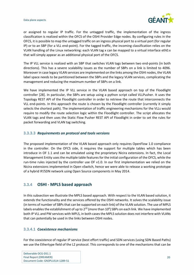
Figure 9. PW implementation in the OSHI node prototype
With this approach it is possible to rewrite the outer source and destination MAC addresses in the
core OSHI network, so that they can match the actual addresses of the source and destination
interfaces of the OSHI IP/SDN routers. This allows to support legacy Ethernet switched networks
among the OSHI IP/SDN routers, which can be an important requirement for a smooth migration from
existing networks.
Both the IP VLL and PW services are realized with SBPs that switches MPLS labels between two end-
points (in both directions). We used the Ryu [38] controller and adapted the VLLPusher python script
to perform the setup of the SBPs. The script uses the Topology REST API of the Ryu controller in order
to retrieve the network topology. Then it evaluates the shortest path that interconnects the end-
points of the service. At this step, it is possible to introduce Traffic Engineering aspects in the selection
of the path. Finally, the script allocates the MPLS labels and uses the Ofctl REST API to set the rules for
packet forwarding and MPLS label switching. In the setup of a PW service the MAC rewriting actions
are added, using the addresses of the OSHI nodes as the outer MAC addresses.
3.3.4.3 Requirements on protocol and tools versions
The MPLS solution needs at least OpenFlow v1.1, in which the handling of MPLS labels has been
introduced. Both the SDN controller and the SDN Capable Switch need to support at least OF v1.1
(most controller and switches jumped from OF v1.0 to v1.3). Considering our tools, an Open vSwitch
version compliant with OF v1.3 has been released in summer 2014, making it possible to start the
implementation of the MPLS based approach. As for the controller, we switched from Floodlight to
Ryu because as of June 2014, only the latter included the support for OF 1.3.
3.3.4.4 The Virtual Switch Service (VSS), also known as VPLS
The PW service can be used as building block for creating more complex services, like for example the
Virtual Switch Service (VSS). While a PW service instance bridges two layer 2 end-points, using the VSS

Data plane aspects
Deliverable OCG-DS1.1 Final Report (DREAMER) Document Code: GN3PLUS14-1289-51
24
service a set of end-points can be transparently bridged into a virtual layer2 switch (see Figure 10).
The ports of a VSS instance correspond to an arbitrary set of ports of the Provider Edge nodes. This
service is called Virtual Private LAN Service (VPLS) in RFC 4761 [37]. A VSS provides the same VPLS
service described in the RFC, but its implementations is based on SDN and does not exploit other
control plane functionalities, therefore we renamed it.
Physical
Virtual
Hybrid network
IP/SDN
OSHI 1
Transparent
Virtual Switch
OSHI 2
OSHI 3 OSHI 4
OSHI 5
Figure 10. Virtual Switch Service (VSS) in the OSHI network
The VSS needs to relay upon the PW service, because using the IP VLL service the OSHI network does
not provide a transparent forwarding of layer 2 packets. The VSS service is built using PWs that connect
the end-points to one or more “bridging points” in the OSHI network in which a virtual layer 2 switch
instance is reserved to bridge the packets coming from the PW.
The deployment of a VSS instance is realized in three steps: the first step is executed by a python script
called VSSelector. It retrieves the topology from the controller and then choices the OSHI nodes that
will host the virtual switches. The second step is the deployment of the virtual switches, according to
the decision taken by the VSSelector, Using the OSHI management tools additional instances of Open
vSwitch are deployed on top of the selected OSHI nodes. The final step is the deployment of the PWs
that will interconnect the CEs to the bridging points (if multiple bridging points are used, additional
PWs will interconnect them as needed. We implemented two versions of the first step (bridging point
selection) : i) un-optimized; ii) optimized. In the un-optimized version a random node from the
topology is chosen and used to deploy the virtual bridge. For the optimized version, we observe that
the selection of an optimal internal topology to implement a VSS exactly corresponds to the Steiner
tree problem [39]. We implemented the heuristic defined in [40] to find an approximate solution of
the minimal Steiner tree. Using the tree topology obtained from the heuristic, a set of virtual switches
is deployed only in the branching points of the tree. These branching points are connected each other
and with end-points through direct Pseudo Wires, In this way, the forwarding of the packets is
optimized, as they are duplicated them only when it is necessary.

Data plane aspects
Deliverable OCG-DS1.1 Final Report (DREAMER) Document Code: GN3PLUS14-1289-51
25
3.3.5 OSHI detailed node architecture
In order to the support of the PW and VSS services, the architecture of an OSHI node needs to be more
complex with respect to the high level architecture shown in Figure 5.
Figure 11 provides a representation of the proposed solution for the PE nodes. The critical aspect is
the support of PW encapsulation and decapsulation (as shown in the right side of Figure 8) in OSHI PE
nodes. The circles refer to the encapsulation steps represented in Figure 8. The OF Capable Switch
only handles the push/pop of MPLS labels, instead the ACE handles the GRE encapsulation. The ACE is
implemented with a separate instance of Open vSwitch and it exploits two virtualization functions
recently introduced in the Linux Kernel: network namespaces and Virtual Ethernet Pairs. For each PW
the ACE has two ports, a “local” port facing toward the CE locally connected to the PE node, and a
“remote” one facing towards the remote side of the PW. The remote port is a GRE port as provided
by OVS, and proper rules are configured in the ACE to bind the two ports. Therefore the ACE receives
customer layer 2 packets on the local ports and sends GRE tunneled packets on the remote port (and
vice-versa). The interconnection of OFCS ports and ACE ports (the endpoints of the yellow pipes in
Figure 11) are realized using the Virtual Ethernet Pair offered by Linux Kernel.
Physical ports
IP Forwarding Engine – IP FE(Linux networking)
IP Routing Daemon
(Quagga)
OF Capable Switch - OFCS (Open vSwitch)
ACcess Encapsulator –ACE
(Open vSwitch)
Pseudo Wire
GRE port
Virtual Ethernet with
IP address
Virtual Ethernet
ACE namespace Root Name Space
2F
3F
4F
2R
3R
4R
1F 1R
Figure 11. OSHI-PE architectural details
For each PW two “Virtual Ethernet Pairs”, are needed. Three endpoints are used as plain switch ports
(two belong to the OFCS, one to the ACE), the last one on the ACE is configured with an IP address and
it is used as endpoint of the GRE tunnel (Virtual Tunnel Endpoint, i.e. VTEP). As regards the GRE port,
it is configured with the IP address of the remote VTEP, the VTEPs are in the same subnet and the ARP
resolution is avoided through a static ARP entry. The interconnection among the namespaces is
assured by means of OpenFlow rules in the OFCS. In the access port (1F) these rules are provided by
the LME at the time of the ACE creation, while in the 4F and 2R cases they are pushed by the OpenFlow
Controller during the PW establishment.
An instance of ACE is used to handle all the PWs of a single Customer Edge (CE): there will be as many
ACE instances as many connected CEs that are using PWs. The ACE runs in a private network

Data plane aspects
Deliverable OCG-DS1.1 Final Report (DREAMER) Document Code: GN3PLUS14-1289-51
26
namespace, and has a private folders tree, as needed to guarantee proper interworking of difference
instances of OVS in the same OSHI-PE.
Coming to the implementation of the VSS, the internal design of an OSHI node that hosts a VSS
Bridging Point (VBP) is shown in Figure 12. The design is quite similar to the one analyzed before for
the PW encapsulation. A VBP is implemented with an OVS instance that does not have local ports, but
only remote ones. A VPB instance represent a bridging point for a single VSS instance and cannot be
shared among VSS instances.
Physical ports
IP Forwarding Engine – IP FE(Linux networking)
IP Routing Daemon
(Quagga)
OF Capable Switch - OFCS (Open vSwitch)
VSS Bridging Point – VBP
(Open vSwitch)
Pseudo Wire
VBP Name Space Root Name Space
Figure 12. An OSHI node that hosts a bridging point for a VSS

Deliverable OCG-DS1.1 Final Report (DREAMER) Document Code: GN3PLUS14-1289-51
27
4 Experimental tools and performance evaluation
With respect to the issue of introducing SDN in ISP networks, let us consider two key aspects:
(i) design, implementation and testing of a solution;
(ii) evaluation of a solution and comparison of different ones.
As for the development and testing of a solution, it ideally requires the availability of a large-scale test
network with real hardware nodes on which to deploy the solution. This is clearly an expensive
approach which is typically not feasible for a researcher or research entity.
The evaluation of a solution (and the comparison among different ones) is a rather complex task. First
of all the functional properties of the solution needs to be assessed: which services can be offered to
the customers and which management tools will be available to the service provider itself. Then
several non-functional properties need to be evaluated (and this is by far the most difficult part). These
properties range from quantitative properties like node performance in processing packets/flows, to
qualitative properties which are more difficult to assess, like “network scalability” or “easiness to
deploy new services”.
In order to support both the development/testing aspects and the evaluation/comparison it is
fundamental to have a realistic emulator platform. The platform should be capable to scale up to
hundreds of nodes and links, representing an IP carrier network at a reasonably large scale. Performing
experiments should be affordable also for research and academic teams, not only for corporate
developers, therefore we advocate the need of an Open Source reference node implementation and
of an Open Source emulation platform. On top of the platform the researcher/developer should be
able to design and deploy services with a minimal effort. The management of these emulation
platforms and the tools for setting up and controlling experiments are also non-trivial problems, for
which we propose an Open Source set of tools called Mantoo (Management tools), described in
section 4.1.
In section 4.2 the Mantoo experimental tools have been used to gather performance measurements
of some aspects related to the data plane solutions (OSHI) developed by DREAMER.

Experimental tools and performance evaluation
Deliverable OCG-DS1.1 Final Report (DREAMER) Document Code: GN3PLUS14-1289-51
28
4.1 Mantoo: Management Tools for SDN experiments on
Mininet and Distributed SDN testbeds
Mantoo is a set of Open Source tools meant to support SDN experiments over emulators and
distributed testbeds. Mantoo is able to drive and help the experimenters in the three phases that
compose an experiment: design, deployment and control. It includes: 1) the Topology 3D (Topology
and Services Design, Deploy and Direct), a web based GUI shown in Figure 13; 2) a set of python scripts
to configure and control emulators or distributed testbeds; 3) a set of scripts for performance
measurements. The overall Mantoo workflow is represented in Figure 16. Using the Topology 3D, the
user can design its experiment in terms of physical topology and services, start the deployment of the
topology and finally run the experiments exploiting the provided measurement tools. The design of
Mantoo and of its components is modular and it can be easily extended to support scenarios that goes
beyond the use cases of our interest. Hereafter, section 4.1.1 describes the Topology 3D GUI, section
4.1.2 the deployment and control phases over the supported testbeds, section 4.1.3 the Measurement
Tools.
Figure 13. The Topology 3D (Topology and Services Design, Deploy & Direct) web Graphical User Interface

Experimental tools and performance evaluation
Deliverable OCG-DS1.1 Final Report (DREAMER) Document Code: GN3PLUS14-1289-51
29
4.1.1 Topology 3D
The Topology 3D offers a web GUI to design a network topology and configure the services for an
experiment (see Figure 13). It consists in a JavaScript client and a Python back-end. A link to a public
instance of the Topology 3D can be accessed from [26]. The Topology 3D is meant to be an extensible
framework, that can support different models of topology and services. A model corresponds to a
technological domain to be emulated and is characterized by the set of allowed node types (e.g.
routers, switches, end-hosts), link types, service relationships and related constraints. As shown in
Figure 16 the Topology 3D takes in input a textual description of the model. The model description is
used to configure the topology designer page, to enforce the constraints when the user is building the
topology and/or during the validation of the topology. So far, we have provided two models: 1) the
OSHI topology domain, including two types of OSHI nodes (Core Routers, Provider Edge routers), the
Customer Edge routers which are also used as traffic source/sinks and the SDN controllers; 2) a generic
layer 2 network with OpenFlow capable switches, end-nodes and SDN controllers. Each model is
decomposed in a set of views. A view is a perspective on a model, which focuses on some aspects
hiding the unnecessary details. For example the OSHI model is decomposed in 5 views: data plane,
control plane and 3 views for the 3 services (IP VLLs, Pseudo Wires and Virtual Switches). In the data
plane view the user can design the physical topology in terms of nodes (OSHI CR and PE, Controllers,
and CEs) and links; in the control plane view the user defines the association of OSHI nodes with
controllers; in the service views the user can select the end points of the services.
The Topology 3D integrates Networkx [25], a pre-existing Python package for the
creation/manipulation of complex networks, making it also possible to randomly generate a data
plane topology with given characteristics.
The Topology 3D exports the representation of the views (topology and services) in a JSON format,
which is the input to the deployment phase described hereafter.
4.1.2 Deployment and control phases
The deployment phase translates the designed topology into the set of commands that instantiate
and configure the nodes and the services for a given experiment. This phase can target different
execution environments for the experiments, by means of a specific “deployer”. So far, we targeted
one emulator (Mininet) and two distributed SDN testbeds (the OFELIA testbed [20] and the GÉANT
OpenFlow Facility - GOFF [41]). We are now planning another deployer that will allow the deployment
and the control of experiment over the Amazon Web Services.
Technically, the deployment phase is performed by a set of python scripts (Topology Deployer) that
parse the JSON file with the representation of the views and produce further scripts (mostly shell
scripts). The proper execution of these scripts deploys the experiment over Mininet or over a
distributed SDN testbeds. The Testbed Deployer (see Figure 14) and Mininet Extensions (see Figure
15) are Python libraries, that are used by the actual deployers. The Mininet Extensions library is
tailored for Mininet emulator, while the Testbed Deployer currently supports the OFELIA and GOFF
testbeds but it can be easily extended to support other testbeds.

Experimental tools and performance evaluation
Deliverable OCG-DS1.1 Final Report (DREAMER) Document Code: GN3PLUS14-1289-51
30
Figure 14. Testbed Deployer Figure 15. Mininet Extensions
4.1.2.1 Mininet Extensions
By default, Mininet only provides the emulation of hosts and switches. We extended Mininet
introducing an extended host capable to run as a router and managed to run the Quagga and OSPFD
daemons on it. Then we have added Open vSwitch to it, as needed to realize the OSHI node. Another
enhancement to the default Mininet setup depends on our requirement to reach the emulated nodes
via SSH from an external “non-emulated” process. To this purpose, we introduce a fictitious node in
the root namespace of the hosting machine, that is connected to the emulated network and works as
relay between the emulated world of Mininet and the “real” world of the hosting machine. The details
on the architecture for the deployment on Mininet can be found in [27]. The Mininet Extensions library
is able to automate all the aspects of an experiment. This includes the automatic configuration of IP
addresses and of dynamic routing (OSPF daemons) in all nodes, therefore it relieves the experimenter
from a huge configuration effort. As for the software design we have to followed a Mininet oriented
design, instead of a big python script that uses the core functionality of Mininet. From an architectural
point of view we have realized Mininet wrappers, extending and overriding when necessary the
default behavior of the Mininet modules. This approach guarantees a more manageable, extensible
and flexible project.
GOFF Deploy
er
OFELIA
Deployer
Testbed Deployer
library
OSHI IP
OSHI Deployer
Mininet Extensions
library
OSHI IP
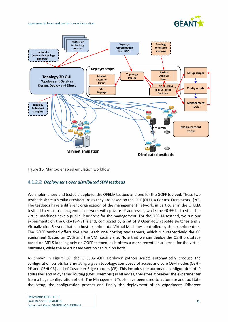
Experimental tools and performance evaluation
Deliverable OCG-DS1.1 Final Report (DREAMER) Document Code: GN3PLUS14-1289-51
31
Setup scripts
Config scripts
ManagementTools
Topologyrepresentation
file (JSON)
Deployer scripts
TopologyParser
networkx(automatic topology
generator)
Topologyto testbedmapping
GOFF - OSHIDeployerOFELIA - OSHI
Deployer
OSHIDeployer
Distributed testbedsMininet emulation
ModelsModelsModels oftechnology
domains
VM servers
Topology 3D GUITopology and Services
Design, Deploy and Direct
MininetExtension
library
TestbedDeployer
library
Topologyto testbedmapping
Measurementtools
Figure 16. Mantoo enabled emulation workflow
4.1.2.2 Deployment over distributed SDN testbeds
We implemented and tested a deployer the OFELIA testbed and one for the GOFF testbed. These two
testbeds share a similar architecture as they are based on the OCF (OFELIA Control Framework) [20].
The testbeds have a different organization of the management network, in particular in the OFELIA
testbed there is a management network with private IP addresses, while the GOFF testbed all the
virtual machines have a public IP address for the management. For the OFELIA testbed, we run our
experiments on the CREATE-NET island, composed by a set of 8 OpenFlow capable switches and 3
Virtualization Servers that can host experimental Virtual Machines controlled by the experimenters.
The GOFF testbed offers five sites, each one hosting two servers, which run respectively the OF
equipment (based on OVS) and the VM hosting site. Note that we can deploy the OSHI prototype
based on MPLS labeling only on GOFF testbed, as it offers a more recent Linux kernel for the virtual
machines, while the VLAN based version can run on both.
As shown in Figure 16, the OFELIA/GOFF Deployer python scripts automatically produce the
configuration scripts for emulating a given topology, composed of access and core OSHI nodes (OSHI-
PE and OSHI-CR) and of Customer Edge routers (CE). This includes the automatic configuration of IP
addresses and of dynamic routing (OSPF daemons) in all nodes, therefore it relieves the experimenter
from a huge configuration effort. The Management Tools have been used to automate and facilitate
the setup, the configuration process and finally the deployment of an experiment. Different

Experimental tools and performance evaluation
Deliverable OCG-DS1.1 Final Report (DREAMER) Document Code: GN3PLUS14-1289-51
32
mechanisms have been used: a management server coordinates the needed operations,
communicating with the rest of the experiment machines through the testbed management network.
It uses the Management Tools project, based on Distributed SHell (DSH), for distributing and executing
remote scripts and commands. Once DSH has been properly configured with the IP of the VMs
belonging to the experiment, it can run commands on a single machine, on a subset (group), or on all
the machines deployed.
The configuration files generated by the deployers have to be uploaded on a site reachable from the
testbed, for example on a webserver running in the management machine. During the deployment
process these files are downloaded by each virtual machine belonging to the experiment. The
deployment is realized through the Management Tools, these scripts simplify as possible the running
of the experiments and speed up the deployment through parallel commands. They relieve the
experimenter from tedious and error prone activities and are able to: i) enable root login, activate
login without password and avoid initial ssh paring; ii) automatically configure the local DSH (we
assume that these scripts are ran by the management server); iii) setup the machines; iv) update
machines already setup; v) configure the experiment; vi) stop the experiment; vii) clean the machines;
viii) change the repository of the configuration files. Other shell commands can be executed leveraging
DSH, obviously as precondition it is necessary to properly configure the above tool. A more detailed
overview of the Management Tools and a typical use-case can be found at [26].
As regards the emulation, each OSHI node and each CE is mapped into a different VM running in one
of the Virtualization Server of a given testbed (OFELIA or GOFF). The Topology to testbed mapping file
contains the association of OSHI nodes and CEs to testbed VMs, the functionality “Mapped” topology,
offered by the Topology 3D, makes this file useless, however it is still used for backward compatibility
with standard topology. An overlay of Ethernet over UDP tunnels is created among the VMs to emulate
the network links among OSHI nodes and between OSHI nodes and CEs.
In our first design we created the tunnels using the user space OpenVPN tool (with no encryption).
The performance was poor, as performing encapsulation in user space is very CPU intensive. Therefore
we considered a second design approach that uses VXLAN tunnels [32] provided by Open vSwitch
(OVS). As explained in [31], OVS implements VXLAN tunnels in kernel space, and this allows to
dramatically improve performance with respect to OpenVPN. The design of the VXLAN tunneling
solution for OSHI over a OCF testbed is reported in Figure 17. We only use VXLAN as a point-to-point
tunneling mechanism (the VXLAN VNI identifies a single link between two nodes) and we do not need
underlying IP multicast support as in the full VXLAN model. The SDN capable OVS is also able to
perform encapsulation and decapsulation of VXLAN tunnels, each tunnel corresponds to a port in the
switch. The VXLAN tunnel ports in Figure 17 are conceptually equivalent to physical ports shown in
Figure 5.

Experimental tools and performance evaluation
Deliverable OCG-DS1.1 Final Report (DREAMER) Document Code: GN3PLUS14-1289-51
33
Virtual ports
VXLAN tunnel “ports”
IP
SDNOF Capable Switch - OFCS
(Open vSwitch)
Physical interface with “testbed”IP address (e.g. 192.168.1.x)
IP forwarding & routing component
eth1.199 port
Ethernetover UDP
Figure 17. Implementing VXLAN tunnels using Open vSwitch (OVS)
4.1.2.3 Control phase (running the experiments)
After the deployment, it is possible to control the experiments by opening consoles on the different
nodes fully integrated in the web GUI of the Topology 3D. The consoles show the output generated
by ssh processes connected to the emulated nodes (deployed in the Mininet emulator or in a virtual
machine hosted in the distributed testbeds). The generated output is conveyed to the terminal shell
running in the experimenter browser, leveraging the WebSocket API, where each terminal has a
separate WebSocket channel.
4.1.3 Measurement Tools
In order to automate as much as possible the process of running the experiments and collecting the
performance data we have developed an object oriented multithreaded Python library called
Measurement Tools (MT). The library offers an intuitive API, that allows the experimenter to “program”
his/her tests. Using the library we can remotely (through SSH) run the traffic generators (iperf) and
gather load information (CPU utilization) on all nodes (VMs). As for the load monitoring, taking CPU
measurements from within the VMs (e.g. using the top tool) does not provide reliable measurements.
The correct information about the resource usage of each single VM can be gathered from the
virtualization environment, for example in Xen based system we can leverage on the xentop tool,
which must be run as root in the hosting XEN server. Therefore for the OFELIA environment we have
developed a python module that collects CPU load information for each VM of our interest in the XEN
host using xentop and formats it in a JSON text file. MT retrieves the JSON file from the python module
with a simple message exchange on a TCP socket. Instead, in the GOFF environment, we cannot
leverage on the same tool used in the OFELIA testbed, because the measurement data are provided
through Zabbix interface [42]. In order to retrieve the necessary information we have extended our
tools, in particular we have realized a python module able to retrieve the data from Zabbix API.

Experimental tools and performance evaluation
Deliverable OCG-DS1.1 Final Report (DREAMER) Document Code: GN3PLUS14-1289-51
34
getVMInfo(VM3)
iperf -s
iperf -c
Figure 18. Measurement Tools in action
It should be noted that the MT offers a general framework simple to extend. To give an example,
instead of iperf tool, we could run new commands with little extensions to the code. Currently we
have developed tools able to generate UDP traffic and able to gather CPU load information from the
virtualization environment. In future, an experimenter can easily extend this framework to run his/her
tests and to measures his/her key indicators.
4.2 Performance evaluation experiments
In this section we analyze some performance aspects of the solutions designed and developed for the
hybrid IP/SDN data plane. During the project lifetime, we had two releases of the experimental
platform (corresponding to the two internal milestones M2 and M4). In the first release we provided
the VLAN tag based mechanism for creating the SBPs, while in the second release we included the
MPLS tag based mechanism. The first 3 experiments described hereafter have been realized using the
first release, the second group of 3 experiments has been run using the final release.
i) IP forwarding performance using OSHI, with reference to the data plane architecture
shown in Figure 5 (section 4.2.1)
ii) Comparison of OpenVPN and VXLAN tunneling for experiments over distributed SDN
testbeds (section 4.2.2)
iii) IP forwarding performance (plain and OSHI) and SBP forwarding in an overlay topology
using tunneling mechanisms over distributed SDN testbeds (section 4.2.3)
In the experiments i, ii and iii we use the iperf tool as traffic source/sink in the CE routers and generate
UDP packet flows from 500 to 2500 packet/s (datagram size is set at 1000 Byte). We evaluate the CPU
load in the PE routers with our xentop based measurement tool. We executes periodic polling and
gather the CPU load of the monitored VMs. In each run we collect 20 CPU load samples with polling
interval in the order of two seconds, the first 10 samples are discarded and the last 10 are averaged
to get a single CPU load value. Then we evaluate the mean (AVG) and standard deviation (DEV) over
20 runs.

Experimental tools and performance evaluation
Deliverable OCG-DS1.1 Final Report (DREAMER) Document Code: GN3PLUS14-1289-51
35
The following 3 experiments have been executed using the final prototype. We have performed these
experiments over GOFF testbed (physical topology is represented in Figure 25) using the overlay
topology shown in Figure 26, the experiments are listed below:
iv) Comparison of VLL and PW forwarding (section 4.2.4)
v) Performance evaluation of the OVS kernel cache (section 4.2.5)
vi) Effect of the increasing the number of OVS flows on the OSHI performance (section 4.2.6)
4.2.1 First performance assessment of OSHI
In this experiment, we consider the design in Figure 5 and compare the OSHI IP forwarding (each
packet crosses the Open vSwitch two times) with ROUTER IP forwarding (the Open vSwitch is removed
and the OSHI node interfaces are directly connected to the IP forwarding engine). We refer to this
scenario as “plain VLAN” as no tunneling mechanism is used. This experiment is not automatically
deployed using the Topology 3D, and we setup a limited topology with two CE nodes and two OSHI
nodes. In this case it is not possible to deploy the IP VLL service and only plain IP router and OSHI IP
have been compared. In the experiment results (see [27] for details) we can appreciate a CPU load
penalty for OSHI IP forwarding with respect to plain IP forwarding in the order of 10%-20%. Apparently,
the CPU load penalty is decreasing in relative terms at higher CPU load, but this is subject to further
evaluation in future experiments. The theoretical CPU saturation rate for plain IP router is in the order
of 14000 p/s. Adding OSHI-IP forwarding reduces the theoretical CPU saturation rate to something in
the order of 12500 p/s.
In all the experiments (including the ones reported in the following subsections) we used UDP
datagram with 1000 bytes length. We had preliminary assessed that packet size had negligible impact
on processing load, by using UDP packets ranging from 100 bytes to 1400 bytes. Performance was only
influenced by the packet rate.
Figure 19 - CPU load vs. packet rate (plain VLAN) Figure 20 – CPU load linear regression (plain VLAN)
0
2
4
6
8
10
12
14
16
18
20
500 1000 1500 2000 2500
%C
PU
load
Packet Rate (p/s)
% CPU Load vs. Packet Rate
OSHI IP
ROUTER IP
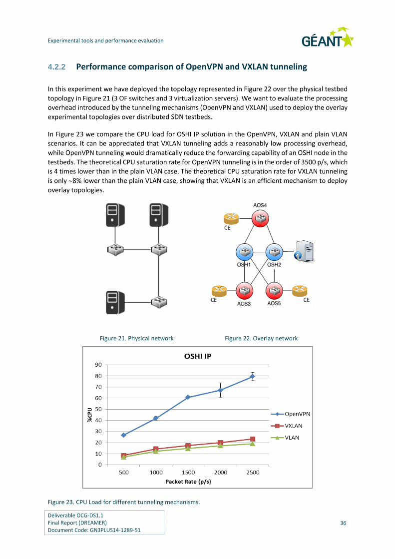
Experimental tools and performance evaluation
Deliverable OCG-DS1.1 Final Report (DREAMER) Document Code: GN3PLUS14-1289-51
36
4.2.2 Performance comparison of OpenVPN and VXLAN tunneling
In this experiment we have deployed the topology represented in Figure 22 over the physical testbed
topology in Figure 21 (3 OF switches and 3 virtualization servers). We want to evaluate the processing
overhead introduced by the tunneling mechanisms (OpenVPN and VXLAN) used to deploy the overlay
experimental topologies over distributed SDN testbeds.
In Figure 23 we compare the CPU load for OSHI IP solution in the OpenVPN, VXLAN and plain VLAN
scenarios. It can be appreciated that VXLAN tunneling adds a reasonably low processing overhead,
while OpenVPN tunneling would dramatically reduce the forwarding capability of an OSHI node in the
testbeds. The theoretical CPU saturation rate for OpenVPN tunneling is in the order of 3500 p/s, which
is 4 times lower than in the plain VLAN case. The theoretical CPU saturation rate for VXLAN tunneling
is only 8% lower than the plain VLAN case, showing that VXLAN is an efficient mechanism to deploy
overlay topologies.
Figure 21. Physical network Figure 22. Overlay network
Figure 23. CPU Load for different tunneling mechanisms.

Experimental tools and performance evaluation
Deliverable OCG-DS1.1 Final Report (DREAMER) Document Code: GN3PLUS14-1289-51
37
4.2.3 Performance analysis on distributed SDN testbed
In this set of experiments we evaluate the processing load of different forwarding solutions over the
distributed SDN testbeds considering the topology shown in Figure 22. For the OSHI solution, we
consider IP forwarding (“OSHI IP”) and SBP forwarding (“OSHI VLL”). Then we consider plain IP
forwarding as a reference (“ROUTER IP”).
We executed the performance tests of OSHI IP, OSHI VLL and ROUTER IP using the VXLAN tunneling
solution. Figure 24 provides reports the experiment results. As shown in Figure 17, in this case in the
plain IP forwarding (ROUTER IP) solutions the packets always cross the Open vSwitch which handles
the VXLAN tunneling, therefore as expected there is no advantage with respect to OSHI IP forwarding.
The OSHI VLL solution is the least CPU intensive and its theoretical CPU saturation rate is in the order
of 13000 p/s. The OSHI IP solution increases CPU load of less than 10%, and its theoretical CPU
saturation rate is in the order of 12000 p/s.
Figure 24. CPU load with VXLAN tunneling.
4.2.4 Performance assessment of PW service
We have performed these experiments over GOFF testbed (physical topology is represented in Figure
25) using the overlay topology shown in Figure 26. In the experiments we use the iperf tool as traffic
source/sink in the CE routers and generate UDP packet flows. We evaluate the CPU load in the OSHI-
PE5 node, by periodically polling to gather the CPU load of the monitored VM. The CPU load samples
are provided by Zabbix every minute, and they report the average calculated in this period with 1-
second-interval sample. We executed a single run and we collected 7 CPU load values, the first 2 are
discarded and the last 5 are averaged to get a single CPU load value.
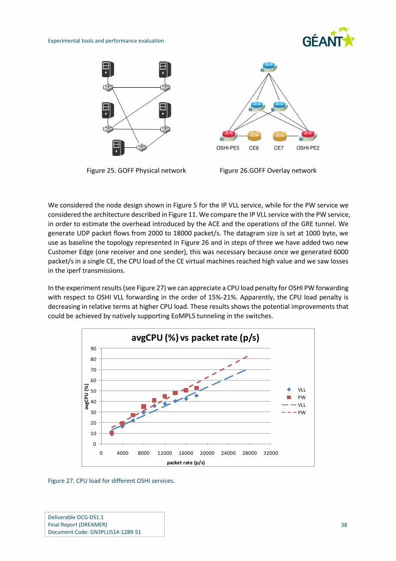
Experimental tools and performance evaluation
Deliverable OCG-DS1.1 Final Report (DREAMER) Document Code: GN3PLUS14-1289-51
38
Figure 25. GOFF Physical network Figure 26.GOFF Overlay network
We considered the node design shown in Figure 5 for the IP VLL service, while for the PW service we
considered the architecture described in Figure 11. We compare the IP VLL service with the PW service,
in order to estimate the overhead introduced by the ACE and the operations of the GRE tunnel. We
generate UDP packet flows from 2000 to 18000 packet/s. The datagram size is set at 1000 byte, we
use as baseline the topology represented in Figure 26 and in steps of three we have added two new
Customer Edge (one receiver and one sender), this was necessary because once we generated 6000
packet/s in a single CE, the CPU load of the CE virtual machines reached high value and we saw losses
in the iperf transmissions.
In the experiment results (see Figure 27) we can appreciate a CPU load penalty for OSHI PW forwarding
with respect to OSHI VLL forwarding in the order of 15%-21%. Apparently, the CPU load penalty is
decreasing in relative terms at higher CPU load. These results shows the potential improvements that
could be achieved by natively supporting EoMPLS tunneling in the switches.
Figure 27. CPU load for different OSHI services.
0
10
20
30
40
50
60
70
80
90
0 4000 8000 12000 16000 20000 24000 28000 32000
avgC
PU
(%
)
packet rate (p/s)
avgCPU (%) vs packet rate (p/s)
VLL
PW
VLL
PW

Experimental tools and performance evaluation
Deliverable OCG-DS1.1 Final Report (DREAMER) Document Code: GN3PLUS14-1289-51
39
4.2.5 Performance analysis of the OVS kernel cache
In the OVS architecture, the first packet of a flow arriving at a node is forwarded to ovs-switchd, a user
space process. Ovs-switchd processes the packet, forwards it (if there exists a matching rule) and
finally installs a “kernel flow”. The kernel flows act like a cache: if another packet belonging to the
same flow arrives in a short time, it will be forwarded using the kernel flow cache, otherwise it will be
forwarded in user space. OVS performance is optimal as long as the packets are forwarded using the
kernel flow cache. The probability of a “cache-hit” depends on the cache size and on the variability of
the input traffic. The aim of this test is to evaluate the importance of the kernel flow cache in OSHI
scenario.
According to the Open vSwitch documentation in the source code, the kernel cache can theoretically
supports up to 200,000 flows. In the Open vSwitch instances that we used in the experiments, the
practical limit was of 10,000 flows. The default idle time before deletion from the cache is ten seconds,
but a kernel flow can be removed earlier due to the cache management policies of Open vSwitch.
In order to evaluate the impact of the kernel cache we generated different traffic patterns with an
increasing number (N) of packet flows, fixing the aggregate packet rate to 12500 packet/s. For each
packet flow in the experiment we used an independent iperf packet generator with rate of 12500/N
packet/s. Part of the packet flows are handled with best effort IP, part with SBPs. There is not a one-
to-one mapping between packet flows and the needed kernel flows: a number of kernel flows are
needed for the best effort IP, regardless of the packet flows, while two kernel flows are needed for a
packet flow handled with SBP (one for each direction). We evaluated the average number of needed
kernel flows for a given traffic pattern, by running an experiment with the default kernel cache size
(10000 entries) and periodically monitoring the number of active kernel flows (using the OVS
command line interface). We used 6 traffic patterns and measured the number of average kernel flows
installed as shown in Table 3.
Table 3 – Average number of kernel flow entries for different traffic patterns
best effort iperf UDP packet flows
VLL SBPs iperf UDP packet flows
average number of kernel flow entries
1 0 9
1 1 11
1 2 13
5 5 17
10 10 22
20 20 43
Then we modified the OVS source code in order to limit the kernel cache dimension to 10 entries.
Figure 28 we report the CPU load with respect to the average needed number of kernel flows. We
observe that the system operates in two states: either the packets are handled by the kernel cache
and the CPU utilization is 40% for the given packet rate, or the packets needs to be processed in user
space and as expected there is a great performance degradation (the CPU load is around 94%).

Experimental tools and performance evaluation
Deliverable OCG-DS1.1 Final Report (DREAMER) Document Code: GN3PLUS14-1289-51
40
0
10
20
30
40
50
60
70
80
90
100
avgC
PU
(%)
avgFlows
avgCPU (%) vs. avgFlows
avgCPU (%)
17 22 439 1311
Figure 28. CPU load with limited kernel cache (10 flows) and increasing average flows.
The design insight that we gather from this experiment, related to our OSHI solution, is that the
number of active SBPs should remain within the limit of the kernel flow table in order to have good
performance. With the hardware configuration that we used in our experiments, this corresponds to
10000 active SBPs.
4.2.6 Effects of larger flow table on the OVS performance
In this experiment we want to evaluate how a larger flow table can influence the forwarding
performance of an OSHI node. We evaluate the OSHI IP forwarding (each packet crosses two time the
OFCS) performance with an increasing number of flows in the Table 0, where the rules for the IP
forwarding are installed. In particular we analyzed two scenarios: kernel cache enabled and disabled.
We fixed the UDP packet rate at 6250 packet/s and installed a variable number of fake flows (they will
never match) from 0 to 5000.
It is to be noted that in all the analyzed cases, the table 0 of the OFCS is not empty, but there are at
least the rules necessary to forward correctly the IP packets. In Figure 29 we report the results of the
experiment.
The increasing number of flows in the table does not influence the forwarding performance in both
cases: kernel cache enabled and disabled. With kernel cache enabled, this is expected. In fact, the
kernel cache will only contain the active flows, irrespective of how many flows are installed in the
switch flow table. On the other hand, with the kernel cache disable all the packets are sent to the user
space daemon that will forward them using the user space table (where there are also the fake flows).
The results in this case show that OVS performance is not influenced by the number of the flows in
the switch flow table.

Experimental tools and performance evaluation
Deliverable OCG-DS1.1 Final Report (DREAMER) Document Code: GN3PLUS14-1289-51
41
Figure 29. CPU load for different number of fake flows installed in the OFCS table.
0
10
20
30
40
50
60
70
80
90
100
0 1000 2000 3000 4000 5000 6000
avgC
PU
(%)
fake flows
avgCPU (%) vs. fake flows
cache en.
cache dis.

Deliverable OCG-DS1.1 Final Report (DREAMER) Document Code: GN3PLUS14-1289-51
42
5 Control plane aspects
Several distributed NOS architectures have been proposed recently to guarantee the proper level of redundancy in the control plane: ONIX [43], Kandoo [44], HyperFlow [45], to name a few. One of the most promising solutions to properly deal with control plane robustness in SDN is ONOS (Open Networking Operating System) [50]. ONOS offers a stable implementation of a distributed NOS and it has been recently released under a liberal open-source license, supported by a growing community of vendors and operators. In ONOS architecture, a cluster of controllers shares a logically centralized network view: network resources are partitioned and controlled by different ONOS instances in the cluster and resilience to faults is guaranteed by design, with automatic traffic rerouting in case of node or link failure. Despite the distributed architecture, ONOS is designed in order to control the data plane from a single location, even in case of large Wide Area Network scenarios. However, as envisioned in the work of Heller et al. [51], even though a single controller may suffice to guarantee round-trip latencies on the scale of typical mesh restoration target delays (200 msec), this may not be valid for all possible network topologies. Furthermore, ensuring an adequate level of fault tolerance can be guaranteed only if controllers are placed in different locations of the network. To this purpose, we designed a geographically distributed multi-cluster solution called ICONA (Inter Cluster ONOS Network Application) which is working on top of ONOS and whose purpose is to both increase the robustness to network faults by redounding ONOS clusters in several locations but also to decrease event-to-response delays in large scale networks. In the rest of the chapter we will consider a large scale Wide Area Network use-case under the same administrative domain (e.g. single service provider), managed by a single logical control plane. ICONA is a tool that can be deployed on top of ONOS; a first release is available under the Apache 2.0 open source license [52]. The ICONA multi-cluster architecture represents an answer to the control plane scalability and resiliency requirements outlined in section 2. The basic scalability and resilience are provided by the ONOS clustering approach: within each cluster the number of ONOS instances can be dimensioned depending on the number of devices to be controlled in the cluster. If one of the ONOS instances in the cluster fails, the other instances can take control of the devices that were controlled by the failing instances. The cluster dimensioning can take into account a maximum number of controller failures to be corrected. The multi-cluster aspects introduced by ICONA enhances the scalability as regards the

Control plane aspects
Deliverable OCG-DS1.1 Final Report (DREAMER) Document Code: GN3PLUS14-1289-51
43
geographical dimension of the provider network. Having a single cluster of controllers (in which all controllers need to reside in the same data center) could be not adequate to cover a large geographical network, with network delays that can be in the order of 100 ms. The ICONA multi-cluster architecture with inter-cluster communication provides the right answer to control providers’ networks with large geographical span. The contribution on control plane is structured as follows. Section 5.1 discusses the state-of-the-art in the field. Section 5.2 provides an overview of ONOS, while section 5.3 presents the ICONA architecture. Some preliminary results are then discussed in section 5.4.
5.1 State of the art in distributed controllers
One of the fundamentals of SDN is the logical centralization of the control plane. It fosters flexibility thanks to the centralized network state view and common management interface with the network devices. On the other hand, this approach introduces some drawbacks and requires a specific design in terms of control network performance, scalability and fault tolerance. Most of the open source controllers currently available are focused on function more than on scalability and fault tolerance. This section provides a review on the literature about SDN distributed architectures that address the scalability and fault tolerance issues. ONIX [43] provides an environment on top of which a distributed NOS can be implemented with a logically centralized view. The distributed Network Information Base (NIB) stores the state of network in the form of a graph; the platform is responsible for managing the replication and distribution of the NIB, the applications have to detect and resolve conflicts of network state. Scalability is provided through network partitioning and aggregation (hiding the details), control over the consistency of the state is provided. In regard to the fault tolerance, the platform provides the basic functions, while the control logic implemented on top of ONIX needs to handle the failures. ONIX has been used in the B4 network, the private WAN [19] that inter-connects Google’s data centers around the planet, using the OpenFlow protocol to control the forwarding devices. The large geographical dimension is addressed through a hierarchical architecture in which multiple sites are considered as logical Autonomous Systems. Within each site, a modified version of the ONIX platform is deployed. A logically centralized application with a global view provides the overall coordination across the multiple sites, providing Traffic Engineering functionality. This high level design is similar to our ICONA solution, but ICONA is not tailored to a specific use case, providing a reusable framework on top of which it is possible to build specific applications (for example Traffic Engineering). The Kandoo [44] architecture faces the scalability issue by creating hierarchical controllers architecture: the so-called root controller is logically centralized and maintains the global network state; the bottom layer is composed by local controllers in charge of managing a restricted number of switches and actions that do not require the network-wide state. Applications, which require a global network view, are managed by the root controller that consequently delegates the requests (e.g., flow installation in the devices) to the local controllers. Applications with a local scope are managed directly by the local controller. The Kandoo architecture does not focus on the distribution/replication of the root controller. Fault tolerance management either in the data and control plane are not considered. A local controller cannot always manage a fault (e.g., link failure between two switches controlled by different local controllers). The consequence is that local controllers should notify the root one and wait before reacting. HyperFlow [45] focuses on both scalability and fault tolerance. Each HyperFlow instance manages a group of devices without losing the centralized network view: the network state is propagated to all the instances through a publish/subscribe mechanism. A control plane failure is managed by

Control plane aspects
Deliverable OCG-DS1.1 Final Report (DREAMER) Document Code: GN3PLUS14-1289-51
44
redirecting the switches to another HyperFlow instance. Such a solution is suited to a data-center scenario, when latencies in the control plane are very short (roughly under 10 ms). In a WAN scenario, where the physical distance, and thus the delay, between the different instances can easily exceed that threshold, this architecture is unable to react fast to network events. DISCO [46] architecture considers a multi-domain environment and provides an East-West interface between different controllers. This approach is specifically designed to control a WAN environment, composed of different geographical controllers that exchange summary information about the local network topology and events. This solution overcomes the HyperFlow limitations, however it does not provide local redundancy: in the case of a controller failure, a remote instance takes control of the switches, increasing the latency between the devices and their primary controller. ElastiCon [47] and Pratyaastha [48] aim to provide an elastic and efficient distributed SDN control plane to address the load imbalances due to static mapping between switches and controllers and spatial/temporal variations in the traffic patterns. Fleet [49], PANE [57] and STN [58] design robust and distributed SDN control planes, which consider the problem of conflicting network-policy updates, each one from a different point-of-view. Fleet aims to resolve the “malicious administrator problem” that arises in a multi-domain administrative environment. PANE considers as scenario the participatory networks, in which the control plane provides a configuration API to its users, applications and end-hosts. Finally, STN “focuses on how to solve concurrency issues that arise from the concurrent execution of control modules on different physical nodes”. SMaRtLight [59] considers a distributed SDN controller aiming at a fault-tolerant control plane. It only focuses on control plane failures, assuming that data plane failures are dealt with by SDN applications on top of the control platform. Its core component is the replicated database that stores all network state. Each replica is “warm” and immediately updated. Scaling of such solution to WAN scenarios is not addressed. The Beacon cluster [60] project also targets the Datacenter scenario, with a general framework focusing on load balancing (with addition and removal of controllers), dynamic switch-to-controller mapping and instance coordination. In OpenDaylight [61], an initial work on clustering has been provided in the last release of the project (Helium), where the Akka framework [62] and the RAFT consensus algorithm [63] have been exploited to realize a clustered version of the data store. At the time of writing, it is not possible for us to assess the maturity of these components in implementing a reliable, available and scalable control platform.
5.2 An overview of ONOS
ONOS (Open Network Operating System) is a distributed SDN controller that has been recently released as open source by ON.Lab as part of a joint community effort with a number of partners including AT&T, NEC and Ericsson among the others [53]. ONOS implements a distributed architecture in which multiple controller instances share multiple distributed data stores with eventual consistency. The whole cluster manages the entire data plane simultaneously. However, for each device a single controller acts as a master, while the others are ready to step in if a failure occurs. With these mechanisms in place, ONOS achieves scalability and resiliency. Figure 30 shows the ONOS internal architecture within a cluster of four instances.

Control plane aspects
Deliverable OCG-DS1.1 Final Report (DREAMER) Document Code: GN3PLUS14-1289-51
45
Figure 30 - ONOS distributed architecture
The Southbound modules manage the physical topology, react to network events and program/configure the devices leveraging on different protocols. The Distributed Core is responsible to maintain the distributed data stores, to elect the master controller for each network portion and to share information with the adjacent layers. The NorthBound modules offer an abstraction of the network and the interface for application to interact and program the NOS. Finally, the Application layer offers a container in which third-party applications can be deployed. In case of a failure in the data plane (switch, link or port down), an ONOS instance detects the event (using the Southbound modules), computes alternative paths for all the traffic crossing the failed element (operation in charge of the Intent Framework), and publishes them on the Distributed Core: then, each master controller configures accordingly its network portion. ONOS leverages on Apache Karaf [54], a java OSGi based runtime, which provides a container onto which various component can be deployed. Under Karaf, an application, such as ICONA, can be installed, upgraded, started and stopped at runtime, without interfering other components.
5.3 The ICONA Architecture
The basic idea behind ICONA is to partition the Service Provider's network into several geographical regions, each one managed by a different cluster of ONOS instances. While the management of the network is still under the same administrative domain, a peer-to-peer approach allows a more flexible

Control plane aspects
Deliverable OCG-DS1.1 Final Report (DREAMER) Document Code: GN3PLUS14-1289-51
46
design. The network architect can select the number of clusters and their geographical dimension depending on requirements (e.g. leveraging on some of the tools being suggested within the aforementioned work [51], without losing any feature offered by ONOS, neither worsening the system performances. In this scenario, each ONOS cluster provides both scalability and resiliency to a small geographical region, while several clusters use a publish-subscribe event manager to share topology information, monitor events and operator's requests.
Figure 31 - ICONA architecture: the data plane is divided in portions interconnected through so-called inter-
cluster links (in red). Each portion is managed by multiple co-located ONOS and ICONA instances, while
different clusters are deployed in various data centers.
The ICONA control plane is geographically distributed among different data centers, each one controlling the adjacent portion of the physical network. Figure 31 shows the aforementioned architecture where each cluster is located in a different data center (e.g. ONOS 1a and ONOS 1b are co-located instances). To offer the same reliability already available in ONOS, the ICONA application runs on top of each instance. Referring on Figure 30, ICONA is deployed in the Application layer, and interacts with ONOS using the Northbound - Intent Framework. Inside each cluster, a master controller is elected, using a distributed registry. The ICONA master is in charge of sharing information and applying decisions, while all the backups are aware of the network status, and can become master in case of failure. The communication between different ICONA instances, both intra and inter-cluster, is currently based on Hazelcast [55]. Hazelcast offers a multicast event-based messaging system, inspired by Java Messaging System (JMS). Applications (e.g. controllers) can publish a message onto a topic, which will

Control plane aspects
Deliverable OCG-DS1.1 Final Report (DREAMER) Document Code: GN3PLUS14-1289-51
47
be distributed to all instances of the application that have subscribed to that topic. Hazelcast does not have a single point of failure that is not achieved easily by pure JMS solutions. In ICONA, one Hazelcast channel is devoted to the intra-cluster communication (e.g. local ONOS cluster) and another one for the inter-cluster messages. ICONA runs as bundle in the ONOS Karaf container, taking advantages of all the features mentioned in Sect. 5.2. In devising a geographical architecture, covering thousands of square kilometers, a key element is the type and amount of information that the different segments of the control plane have to share. Control traffic has to be minimized and the system has to optimize is performance in terms of:
Offering an up-to-date view of the network, including status of the nodes,
Configuring the network devices,
Reacting to failures both in data and control plane without disrupting customer's traffic. Three internal modules implement these features in ICONA (see Figure 31): the Topology Manager, the Service Manager and the Backup Manager. In the following Sections an overview of each of these components is provided.
5.3.1 Topology Manager
The Topology Manager (TM) is responsible to discover the data plane elements, reacts to network events, stores in a persistent local database the links and devices with the relevant metrics. To offer a partial view of its network portion, each TM shares with the other ICONA clusters the following information through the inter-cluster channel:
Inter-cluster link (IL): an IL is the physical connection between two clusters. ICONA
implements an enhanced version of the ONOS discovery mechanism, based on the Link Layer
Discovery Protocol (LLDP). Each IL is shared with all the clusters tagged by some metrics, such
as the link delay, available bandwidth and number of flows crossing the link.
End-point (EP) list: an EP defines the interconnection between the customer's gateway router
and the ICONA network. Each cluster shares the list of its EPs and the metrics (bandwidth,
delay) between these EPs and all the clusters ILs.
5.3.2 Service Manager
The Service Manager (SM) handles all the interaction between the network operators and the control plane. This module offers a REST API used to poll ICONA for network events and alarms, and to manage (instantiate, modify and delete) the services. In our initial implementation, we have considered only two services: L2 pseudo-wire tunnels and MPLS VPN overlay networks, which are key services in a Service provider network. However, the application can be easily extended to provide other functionalities. The implemented services require interconnecting two or multiple EPs that can be controlled by the same ICONA cluster or by different ones. The SM computes the overall metrics and chooses the best path between two EPs. There are two cases:
If they belong to the same cluster, it directly asks ONOS to install an OpenFlow 1.3 [18] MPLS-
based flow path in the physical devices.

Control plane aspects
Deliverable OCG-DS1.1 Final Report (DREAMER) Document Code: GN3PLUS14-1289-51
48
If they belong to two different clusters, the SM follows this procedure:
o It contacts all the involved clusters (e.g. the ones that are crossed by this service
request) asking to reserve the local portion of the path.
o As soon as all the clusters have replied to the reservation event (if at least one does
has a negative reply, the SM releases the path and computes an alternative ones), it
requests to switch from the reservation status to the installation. Each ICONA cluster
master then contacts the local ONOS asking to install the flow path in the physical
devices.
o If the second step is successful too, the SM ends the procedure, otherwise it asks all
the clusters to release the resources, computes an alternative route and restarts the
procedure. Finally, the SM updates all the ICONA clusters with the new installed service and the relevant information. While this path installation procedure is slower than the original implemented by ONOS (around three times), ICONA cannot assume a strong consistency between the remote databases. In the aforementioned ISP scenarios, the amount of time required for a service installation is not a relevant metric, but the procedure has to be robust enough to tolerate substantial delays.
5.3.3 Backup Manager
If a failure happens within the same cluster, ONOS takes care of rerouting all the paths involved in the failure. After receiving a PORT_STATUS or LINK_DOWN OpenFlow message, ONOS detects all the flows crossing the failed element and computes an alternative path to the destination. Finally, it installs the new flows in the network and removes the old ones. If instead the failure happens between two different clusters (e.g. it involves an IL or one of the two nodes that sits at the edge of the IL) then the ICONA's module named Backup Manager (BM) will handle the failure. In particular:
For each IL, a backup link (BIL) completely decoupled from the primary one, is computed and
pre-installed in the data plane. The BIL is a virtual link selected among all the available paths
between the source and destination ICONA clusters, taking into account composite metrics,
such as the delay, available bandwidth and numbers of flows.
When the failure happens, all the traffic crossing the IL is rerouted to the BIL by each ICONA
edge cluster, without the need to wait for remote instances to share any information.
When the rerouting is completed, the new path is notified to all the remote clusters, in order
to share the same network status. The amount of time required for the rerouting is particularly relevant in an ISP network because it is most directly related to SLAs guaranteed by network operators.
5.4 Evaluation

Control plane aspects
Deliverable OCG-DS1.1 Final Report (DREAMER) Document Code: GN3PLUS14-1289-51
49
The purpose of the experimental tests described in this section is to compare ICONA with a standard ONOS setup, and evaluate the performances of the two solutions in an emulated environment. The control plane is always composed of 8 virtual machines, each with four Intel Core i7-2600 CPUs @ 3.40GHz and 8GB of RAM. While for the ONOS tests all the instances belong to the same cluster, with ICONA we have created 2, 4 and 8 clusters, respectively with 4, 2 and 1 instances each. The data plane is emulated by Mininet [65] and Netem [56]: the former creates and manages the OpenFlow 1.3 [18] network, while the latter emulates the properties of wide area networks, such as variable delay, throughput and packet loss. In particular, we have created multiple data plane topologies, emulating grid networks and the GÉANT facility using Mininet. Mininet allows specifying some useful parameters that can be associated to links and switches, such as bandwidth, delay and packet loss. In addition to the data plane impairments, we have also set the control plane characteristics using Netem. This tool has been used to set bandwidth, delay and packet loss in the interfaces of the 8 VMs running the control plane and interconnecting it with the data plane. Both solutions (ONOS and ICONA) have been tested with both a regular (grid) topology and with the topology of the GÉANT [1] pan-European network. It is important to highlight that the current ONOS release (Avocet 1.0.1) is focusing on functions and correctness, while Blackbird, to be released in March, will dramatically improve the internal performance. For these reasons, the results presented in this section should not be considered as benchmark.
5.4.1 Reaction to Network Events
5.4.1.1 Grid networks
The first performance metric is the overall latency of the system for updating the network state in response to events; examples include rerouting traffic in response to link failure or moving traffic in response to congestion. To evaluate how the system performs when the forwarding plane scales-out, we have selected some standard grid topologies, with a fixed link delay of 5ms (one-way) and then we have been comparing the latency needed to reroute a certain number of installed paths when an inter-cluster link fails for both ONOS and ICONA with various clustering settings.
We define as overall latency the amount of time that both ONOS and ICONA require to react to the failure as the sum of:
The amount of time for the OpenFlow messages (PORT_STATUS and FLOW_MOD) to
traverse the control network,
The alternative path computation,
The installation of new flows in the network devices and
The deletion of the pre-existing flows. In particular, we have been running several simulations by installing one thousand paths in the network and then by making fail an inter-cluster link with at least one hundred pseudo-wires running.
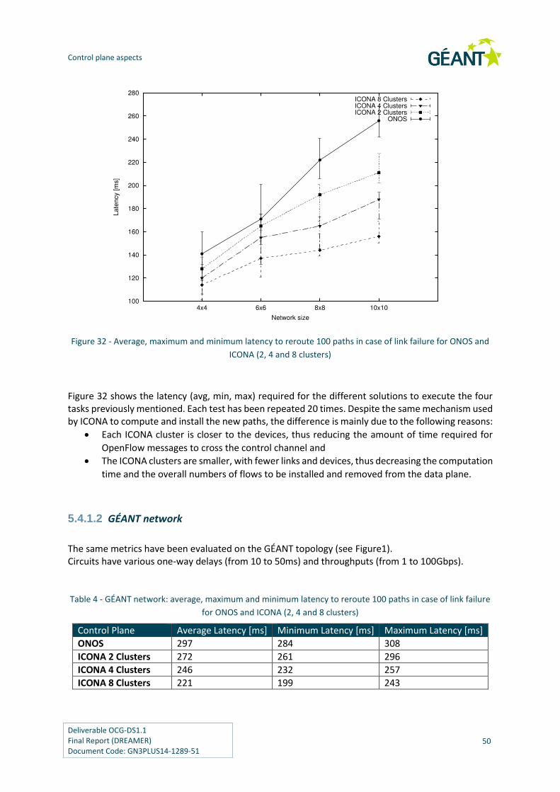
Control plane aspects
Deliverable OCG-DS1.1 Final Report (DREAMER) Document Code: GN3PLUS14-1289-51
50
Figure 32 - Average, maximum and minimum latency to reroute 100 paths in case of link failure for ONOS and
ICONA (2, 4 and 8 clusters)
Figure 32 shows the latency (avg, min, max) required for the different solutions to execute the four tasks previously mentioned. Each test has been repeated 20 times. Despite the same mechanism used by ICONA to compute and install the new paths, the difference is mainly due to the following reasons:
Each ICONA cluster is closer to the devices, thus reducing the amount of time required for
OpenFlow messages to cross the control channel and
The ICONA clusters are smaller, with fewer links and devices, thus decreasing the computation
time and the overall numbers of flows to be installed and removed from the data plane.
5.4.1.2 GÉANT network
The same metrics have been evaluated on the GÉANT topology (see Figure1). Circuits have various one-way delays (from 10 to 50ms) and throughputs (from 1 to 100Gbps).
Table 4 - GÉANT network: average, maximum and minimum latency to reroute 100 paths in case of link failure
for ONOS and ICONA (2, 4 and 8 clusters)
Control Plane Average Latency [ms] Minimum Latency [ms] Maximum Latency [ms]
ONOS 297 284 308
ICONA 2 Clusters 272 261 296
ICONA 4 Clusters 246 232 257
ICONA 8 Clusters 221 199 243

Control plane aspects
Deliverable OCG-DS1.1 Final Report (DREAMER) Document Code: GN3PLUS14-1289-51
51
Table 4 depicts similar results as the previous test. ONOS has been compared with three different ICONA deployments, with 2, 4 and 8 clusters, respectively with 4, 2 and 1 instances each. While having the same number of VMs running the control plane software, their geographical distribution improves the overall performance of the system. While the network is smaller than the 10*10 grid topology, with 41 switches and 58 bi-directional links, the higher delay in the data plane requires an additional amount of time to reconverge.
5.4.2 Startup Convergence Interval
This second experiment measures the overall amount of time required for both solutions to re-converge after a complete disconnection between the control and data planes. The tests have been performed over the GÉANT topology, and replicated 20 times. Table 5 shows the average, maximum and minimum values in seconds.
Table 5 - Amount of time required to obtain the network convergence after disconnection for ONOS and
ICONA
Control Plane Average Latency [s] Minimum Latency [s] Maximum Latency [s]
ONOS 6,98 6,95 7,06
ICONA 4 Clusters 6,96 6,88 7,02
The result shows that ICONA and ONOS require comparable time intervals to return to a stable state, in case of a complete shutdown or a failure of the control plane.
5.5 Integration of ICONA and OSHI
Conceptually the ICONA and OSHI solutions can interwork, as ICONA is using ONOS; which in turn is
using OpenFlow to control the network devices and an OSHI node is just a specific network device.
On the other hand, some details needs to be fixed for having a running interoperability, considering
that ONOS by default is configured to operate on a pure layer 2 network, while we introduce the
Hybrid IP/SDN networking.
1) Within the ONOS controller the “automatic layer 2 forwarding” of packets needs to be
disabled (the module is called iForwarding).
2) The handling of ARP within ONOS needs to be disabled as well (in particular the ProxyArp
module and the HostLocationProvider module, we do not need them)
3) For the IP VLL service, the implementation of MPLS tunnels in ONOS (provided by DREAMER)
does not support the second MPLS path based on MPLS multicast Ethertype which we use to
carry ARP packets in the VLLs. Either static ARP is added at the VLL end-point or the support
for the second MPLS path based on MPLS multicast Ethertype should be added

Control plane aspects
Deliverable OCG-DS1.1 Final Report (DREAMER) Document Code: GN3PLUS14-1289-51
52
4) For the PW service, the implementation of MPLS tunnels in ONOS (provided by DREAMER)
does not support hop-by-hop MAC rewriting. The functionality of the PW should be preserved,
but the customer edge virtual MAC of the GRE endpoint will be exposed in the core.
All these features require that ICONA diverge from ONOS, because OSHI behavior can only be obtained
with modifications inside the core modules of ONOS. In order to maintain ICONA as general as possible,
thus allowing other researchers to use and contribute to it, we choose not to fully integrate the OSHI
data plane in the main ICONA software release, but we are planning a joint demo that will be probably
hosted at the next ONS conference (June 2015), in which we will show how ICONA and OSHI can
smoothly interoperate. This code base will then be uploaded to GitHub in a separate branch.
Deliverable OCG-DS1.1 Final Report (DREAMER) Document Code: GN3PLUS14-1289-51
53
6 Future work
6.1 OSHI: gap analysis, ongoing and future work
Let us consider solution for PW encapsulation described in section 3.3.4, based on GRE tunneling
performed by the ACE. It has been designed as a replacement of the more efficient Ethernet over
MPLS (EoMPLS) encapsulation described in [35], which cannot be realized by the current version of
Open vSwitch. The GRE tunneling introduces a transport and a processing overhead. The transport
overhead is 20 (IP header) + 16 (GRE header) bytes for each packet. The processing overhead depends
on the implementation architecture, our solution (shown in Figure 11) was not meant to be highly
efficient, but only to demonstrate the feasibility of the approach with a working component. We do
not plan to improve the efficiency of the solution, rather we believe that native Ethernet over MPLS
(EoMPLS) encapsulation should be provided by open source switches and we are considering to
extend the Open vSwitch or other open source switches to support EoMPLS.
Assuming that a switch supports EoMPLS, a second important gap to be filled is the lack of support for
such tunneling operations in the OpenFlow protocol. Note that the lack of encapsulation support in
OpenFlow does not only concern EoMPLS, but also other tunneling solutions like GRE, VXLAN, Ethernet
in Ethernet. In fact, while it is possible to some extent with OpenFlow to control GRE and VXLAN
packets already tunneled (and specific matches have been introduced in OF 1.4 for VXLAN), it is not
possible to control the encapsulation (i.e. pushing the GRE, VXLAN or simply an additional Ethernet
headers) and decapsulation (i.e. popping the header) operations. Currently, external tools are needed
to manage the tunnel end-points (e.g. using the switch CLIs - Command Line Interfaces), with added
complexity in the development, debug and operations. Having the possibility to configure the
tunneling end-points on a OF capable switch from the SDN controller by means of the OpenFlow
protocol would be a great simplification in the management of SDN based services.
We observe that the described OSHI solution represents an open starting point to design and
implement additional “core” functionality and user oriented services following the SDN paradigm. As
for the core functionality we are now considering protection/restoration and traffic engineering
mechanism. For traffic engineering we have already implemented a flow assignment heuristic for
optimal mapping of PWs with required capacity on the core OSHI links. As for additional services, we
are considering the realization of the Layer 3 VPNs on top of the PW service. Following the same
approach used for the VSS service, the idea is to deploy virtual router instances within the OSHI nodes
that can exchange routing information with routers in the CE nodes. Finally, we mention our ongoing
work on an Open Source implementation of Segment Routing [33] on top of OSHI. All these ongoing
efforts are reported on the OSHI web page [26], including links to preliminary results and source code.

Future work
Deliverable OCG-DS1.1 Final Report (DREAMER) Document Code: GN3PLUS14-1289-51
54
6.2 ICONA: future work
A preliminary release of ICONA is available under permissive open source license (Apache 2.0) and we are collaborating with ON.Lab to evaluate the opportunity to include some of the ideas developed therein as part of the official release of ONOS. Future improvements of ICONA will focus on solutions to improve the path installation procedure and on combining clustering design techniques with ICONA deployment in order to guarantee the best tradeoff between performances and replication of clusters in different network locations. Moreover, while this first prototype already implements the core functionalities of the envisioned architecture, it still misses some key features, such as:
A more advanced routing algorithm, evolving the Shortest Path First one, that takes in account
advanced metrics between remote data plane clusters
The service portfolio needs to be extended to support customer’s requests and use cases
The current communication channel, based on JMS Hazelcast, can be further investigated, and
maybe replaced with another mechanism However, taking in account that all the software is based on a well-known open source control plane (ONOS), we would like not only to extend the work done in other projects, but also to share our results with the community, waiting for interested researchers to test and contribute to ICONA.

Deliverable OCG-DS1.1 Final Report (DREAMER) Document Code: GN3PLUS14-1289-51
55
7 Project impact
The highlights of DREAMER impact are reported in the following bullet list.
o The OSHI nodes source code has been released and we have already received some expression of interest and feedback by other researchers that are using it. In particular we have opened a public mailing list about OSHI, it currently has 17 subscriber, of which 11 are people external to the project. 4 people external to the project have posted questions and feedback so far.
o The Topology 3D tool is re-usable for designing and executing SDN experiment over Mininet emulator and over different testbeds.
o The project has contributed to the design and development of the ONOS controller. The MPLS intent has been developed: now it is possible to created MPLS label switched path using ONOS.
o The ICONA application for the coordination of distributed clusters of ONOS controller will contribute to the realization of such coordination in future releases of ONOS controller.
o The project has contributed to the progress of the Open vSwitch Open Source project. In particular it has provided a feedback on the support of multiple nested MPLS labels. The OVS version that was officially released was not able to properly handle MPLS label stacking. Thanks to our problem reports and following some iterations on the ovs-discuss mailing list, the issue has been fixed by the core OVS development team.
o The project has published 2 papers, one demo paper and a poster to refereed conferences, submitted one more conference paper and a journal paper, and has given 3 presentations to public events (see sections 7.1 and 7.2 for the details). The project will showcase a demo at the 1st IEEE Conference on Network Softwarization (Netsoft 2015), London, UK, 13-17 April 2015. The project is preparing a demo between ON.LAB-Internet2 and GÉANT-DREAMER testbeds to be shown at ONS 2015 (15-18 June 2015, Santa Clara US).
o The DREAMER project has organized the Workshop “Software Defined Networking and its applications: where are we now?” (http://netgroup.uniroma2.it/twiki/bin/view/DREAMER/SdnWorkshop), held in Rome, June 9th 2014, which saw the participation of 60 people from academia and industry.
Project impact
Deliverable OCG-DS1.1 Final Report (DREAMER) Document Code: GN3PLUS14-1289-51
56
7.1 Scientific papers, demo, posters
S. Salsano, P. L. Ventre, L. Prete, G. Siracusano, M. Gerola, E. Salvadori,
“Open Source Hybrid IP/SDN networking (and its emulation on Mininet and on distributed SDN
testbeds)”, 3rd European Workshop on Software Defined Networks, EWSDN 2014, 1-3 September 2014, Budapest, Hungary http://arxiv.org/abs/1404.4806
S. Salsano, N. Blefari-Melazzi, F. Lo Presti, G. Siracusano, P. L. Ventre,
“Generalized Virtual Networking: an enabler for Service Centric Networking and Network Function
Virtualization”, 16th International Telecommunications Network Strategy and Planning Symposium, Networks 2014, 17-19 September 2014 http://arxiv.org/abs/1409.5257
Mauro Campanella, Luca Prete, Pier Luigi Ventre, Matteo Gerola, Elio Salvadori, Michele Santuari, Stefano Salsano, Giuseppe Siracusano
"Bridging OpenFlow/SDN with IP/MPLS", poster presentation at TNC2014, 19 - 22 May 2014, Dublin, Ireland http://netgroup.uniroma2.it/Stefano_Salsano/papers/DREAMER-tnc2014-poster.pdf
M. Gerola, M. Santuari, E. Salvadori, S. Salsano, P. L. Ventre, M. Campanella, F. Lombardo, G. Siracusano,
"ICONA: Inter Cluster ONOS Network Application", demo paper accepted to 1st IEEE Conference on Network Softwarization (Netsoft 2015), London, UK, 13-17 April 2015 http://netgroup.uniroma2.it/Stefano_Salsano/papers/ icona_netsoft2015_demo.pdf
M. Gerola, M. Santuari, E. Salvadori, S. Salsano, M. Campanella, P. L. Ventre, A. Al-Shabibi, W. Snow,
"ICONA: Inter Cluster ONOS Network Application", submitted to SOSR 2015 - ACM Sigcomm Symposium on SDN Research, Co-located with Open Networking Summit 2015 http://arxiv.org/abs/1503.07798
S. Salsano, P. L. Ventre, F. Lombardo, G. Siracusano, M. Gerola, E. Salvadori, M. Santuari, M. Campanella,
"OSHI - Open Source Hybrid IP/SDN networking and Mantoo - a set of management tools for
controlling SDN/NFV experiments", to be submitted to IEEE Transactions on Network and Service Management
7.2 Presentations, posters, videos
Presentation of "Open Source Hybrid IP/SDN networking (and its emulation on Mininet and on
distributed SDN testbeds)" (see full paper info above) at EWSDN 2014 http://netgroup.uniroma2.it/Stefano_Salsano/papers/salsano-oshi-ewsdn-2014-pptx.pdf
Stefano Salsano, Pier Luigi Ventre (speaker), Luca Prete, Giuseppe Siracusano, Matteo Gerola, Elio Salvadori,
"OSHI - Open Source Hybrid IP/SDN networking (and its emulation on Mininet and on distributed
SDN testbeds)", talk given at GTTI 2014 Annual Meeting, June 19, 2014, Palermo, Italy. Selected as winner of
"Premio Carassa 2014" for the best paper on the "Networking" topic co-authored and presented by a young researcher. http://netgroup.uniroma2.it/twiki/pub/DREAMER/WebHome/oshi-gtti14-v11ss-external-video.pdf
Pier Luigi Ventre, Stefano Salsano, Giuseppe Siracusano, Francesco Lombardo,
"OSHI video demo June 2014" (oshi-v5.wmv file (80 MB)) https://www.dropbox.com/s/5ahmuiqlcr3wnue/oshi-v5.wmv

Project impact
Deliverable OCG-DS1.1 Final Report (DREAMER) Document Code: GN3PLUS14-1289-51
57
Stefano Salsano,
"The DREAMER project", presentation in the session "Looking ahead to network services", GEANT Symposium, Tuesday 24th Feb, Athens, Greece http://netgroup.uniroma2.it/twiki/pub/DREAMER/WebHome/dreamer-gn3plus-symposium-v08ss.pdf
"DREAMER video demo February 2015" @ GEANT Symposium https://www.dropbox.com/s/kyolyns4bqyrkxx/dreamer-gn3plus-symposium-2015-v02.mp4?dl=0

Deliverable OCG-DS1.1 Final Report (DREAMER) Document Code: GN3PLUS14-1289-51
58
8 Conclusions
The DREAMER project focused on introducing and exploiting Software Defined Networking (SDN)
capability in carrier grade IP backbones. The objective of the DREAMER proposal was to investigate
how a network based on an OpenFlow/SDN control plane can provide the same functionalities of an
IP/MPLS control plane, offering a carrier grade approach to resiliency and fault management.
DREAMER considered the operational requirements coming from the GARR National Research and
Education Network (NREN) to drive the design of the solutions.
The DREAMER project had two main dimensions: scientific and experimental. The scientific dimension
considered a resilient SDN system able to smoothly operate in case of link and node failures, by
providing resiliency to the controller element and by promptly restoring paths in the data plane. The
experimental dimension implemented and validated the designed modules over the testbed facilities
provided by GÉANT.
The project has contributed in three main areas of OpenFlow/SDN research: data plane, control plane
and experimental tools.
As for the Data Plane, IP and SDN hybrid networking has been considered, by designing the “OSHI”
solution (Open Source Hybrid IP / SDN networking) and implementing it over Linux OS. An OSHI node
combines traditional IP forwarding/routing (with OSPF) and SDN forwarding implemented by means
of Open vSwitch in a hybrid IP/SDN node. No open source solutions for such a hybrid node were
available. Using the OSHI solution, DREAMER demonstrated services like Layer 2 Pseudo Wires (PW)
and Layer 2 Virtual Switches over an IP backbone.
As for the Control Plane, the project exploited and contributed to the development of ONOS Open
Source controller. Thanks to an official agreement of the partners with ON.LAB (a research lab on SDN
based in San Francisco), the DREAMER project partners were able to work on the ONOS source code
before it was released to the general public. The contribution of the project is a solution to distribute
the control of a geographical scale SDN network among a set of clusters of ONOS controllers. The
solution is called “ICONA” (Inter Cluster ONos Application). ONOS features provide data plane
resilience, as well as control plane resilience for a single cluster of controllers in the same data center.
As for the experimental tools, the project has developed the “Topology 3D” tool (Topology Designer,
Deployer & Director) that provides an easy design, deployment and control of the SDN experiments.
It consists in a web front end that allows to graphically design a network topology (made of L3 routers,
L2 switches, end devices) and to configure the set of services to be provided on top. Then the topology
can be automatically deployed as an overlay network over a distributed testbed (e.g. the GÉANT

Conclusions
Deliverable OCG-DS1.1 Final Report (DREAMER) Document Code: GN3PLUS14-1289-51
59
testbed) or within a Mininet emulator. Finally, the web front end allows to access the shell interface
on each node of the deployed topology.
DREAMER has implemented prototypes of the proposed solutions based on Open Source tools and
has contributed to the development of some of these tools. Therefore DREAMER is having an impact
towards the availability of a truly open ecosystem for carrier grade backbone IP networks based on
the SDN paradigm. See also section 8.2 for a discussion on taking DREAMER results to the real world.
Finally, we would like to highlight impact and future fostered by the DREAMER project.
o The hybrid IP/SDN approach is of interest for the GÉANT evolution. The definition of provided services (Pseudo Wires, Virtual Layer 2 Switches) and the SDN architecture to control such services proposed by DREAMER is of interest of the GÉANT community. It naturally fits in the “Future Network Services” topic that will be addressed by the GÉANT community in the short term future.
o The research will continue in GN4 year 1 in the JRA2 activity.
o The Topology 3D tool could be easily extended to support the GTS (GÉANT Testbed Service), in particular it could be used to produce a testbed description in the DSL format starting from a graphical representation.
o The DREAMER project has identified limitation in the OpenFlow protocol and in the OpenFlow capable open source switches (e.g. Open vSwitch) as far as the support of Ethernet over MPLS encapsulation. These limitations have been circumvented with workaround in the DREAMER project. The development of cleaner and more efficient solutions, which could also be improved with extensions to the OpenFlow protocol is of great interest for a continuation of the project.
o Further services and applications on top of the already developed solutions can be investigated. We are already focusing on a SDN based segment routing solution exploiting the DREAMER results (OSHI Open Source nodes and network architecture).
8.1 Comparison of final results with requirements
The text within frames is extracted from section 2 (Requirement analysis)
The functionalities that DREAMER has to provide, with carrier grade characteristics are:
virtual point to point circuit creation at layer 2 (emulation of Ethernet circuits), with and
without automatic resiliency
DREAMER has designed and implemented the IP VLL and Layer 2 PW services in the OSHI nodes. Both
services have been realized with SDN Based Paths using MPLS labels. The ONOS controller has been
modified to support the creation of MPLS paths, this is meant to be the “carrier grade”
implementation at the control plane level, as it relies on all the scalability and resilience characteristics
of ONOS. An implementation based on Ryu controller is also available, which is useful for fast
prototyping and proof of concepts.

Conclusions
Deliverable OCG-DS1.1 Final Report (DREAMER) Document Code: GN3PLUS14-1289-51
60
a VPN functionality similar to the one that can be created with MPLS (the BGP/MPLS solution
uses BGP to distribute VPN routing information across the provider's backbone and MPLS to
forward VPN traffic from one VPN site to another)
DREAMER has implemented a Layer 2 virtual switch service using OSHI nodes, called VSS (Virtual
Switch Service). This service corresponds to the VPLS (Virtual Private LAN Service) service [37], but
uses an SDN approach for the service establishment. The OSHI node architecture that has been
designed and implemented makes it relatively easy to implement also a Layer 3 VPN like the
BGP/MPLS, because a separate Linux network namespace is used in the Provider Edge nodes to
process the packets of a given customer.
traffic engineering of flows (implementation of specific algorithms is out of scope for
DREAMER project)
The use of Traffic Engineering algorithms in the selection of paths performed by the controller can be
decided by the controller itself (or by the “application” running on top of the controller). This was not
considered among the high priority tasks in the requirement analysis. DREAMER has started some
exploratory work on this using the control plane implementation based on the Ryu controller. For
traffic engineering we have implemented a flow assignment heuristic for optimal mapping of PWs with
required capacity on the core OSHI links. The optimality criteria was related to the equalization of
maximum link load.
Given the multi-domain nature of the European NREN and the need to provide virtual private
networks that span more than one NREN, the DREAMER architecture and functionalities it should be
possible to extend it toward multi-domain stitching of virtual circuit at layer 2 and at layer 3, either
manually or automatically.
The ICONA inter cluster solution from an algorithmic point of view lends itself also to be revisited as
inter-domain solution (no work in this direction has been performed during the DREAMER project
timeframe).
Two architectural aspects, will be specifically targeted:
i) the control plane controller resilience and its distribution;
The ONOS controller is designed to address resilience. It provides resilience with respect to controller
failures by having a local cluster of controller and a shared data base. The ICONA solution has targeted
the distribution of the control plane across a set of controller clusters that can be placed in remote
geographical locations. Only single-domain scenarios have been considered.
ii) the data plane resilience, with carrier grade fast restoration mechanism.
The ONOS controller is able to enforce mechanism for data plane resilience, including fast restoration.
The performance of some mechanisms depend on the delay between the controller and the controlled
network devices. Therefore the ICONA multi-cluster solution is able to reduce this delay by distributing
the control among a set of clusters placed in remote locations.

Conclusions
Deliverable OCG-DS1.1 Final Report (DREAMER) Document Code: GN3PLUS14-1289-51
61
8.2 Taking DREAMER to the real world
The work done on the OSHI architecture with the development of the Open Source OSHI node is
already usable for performing experiments and emulations of Hybrid IP/SDN networking on single
nodes (using Mininet) or on a distributed testbed. It does not target line speed performance
implementation in real Provider Edge or Core Routers node. In this respect the Mantoo tools represent
the natural complement, helping the experimenters to setup and manage complex emulated hybrid
IP/SDN networks.
The work done on ICONA architecture will be pushed to the mainstream of the ONOS controller. The
setup of MPLS paths has already been integrated in the ONOS mainstream and represent a notable
contribution developed by DREAMER. The ICONA results will be discussed within the ONOS
community, as the DREAMER partners intend to push these results and to contribute to their
integration into ONOS.
The contribution, whether or not is fully or partially accepted is a positive contribution to the
development of a commercial product that satisfies the requirements. If accepted, its further
implementation developments and maintenance will also be undertaken by the ONOS community,
possibly benefitting by some of the improvements described in section 6.2.

Appendix
Deliverable OCG-DS1.1 Final Report (DREAMER) Document Code: GN3PLUS14-1289-51
62
9 Appendix
This section provides a brief description of the software released, and reports pointer to the released
code. In particular, the Appendix includes the software of the Hybrid IP/SDN node (T 1.3), of the SDN
mechanisms to support resilience (T 1.4), and of the deployment tools (T 1.5). Topology Deployer and
Mantoo have been developed as components parts of the T 1.5.
All the code released for this milestone is using the “liberal” Open Source license Apache 2.0 [64] and
links to public git repositories are given in this appendix.
Appendix A reports a brief description of the Hybrid IP/SDN node (OSHI) and the related project
(Dreamer-Setup-Scripts). The appendix ends with pointers to the released code, links for the how-to
documents and for ready-to-go Virtual Machine, already configured with all the OSHI software, where
the experimenter can run OSHI networks in the Mininet [65] emulation environment.
Appendix B includes the DREAMER Network Operating System (ONOS and ICONA) installation and
configuration procedures. The guide will help the user in the whole process of setting up the hardware,
install the required software packages and configure them to have a running environment. Finally, the
latest sub-chapter introduces the console interface, through which the operator can interact with
ICONA, to control and monitor the underlined SDN network.
Appendix C describes the Mantoo project, a set of Open Source management tools for the emulation
of the DREAMER solutions over the Mininet emulator and over distributed testbeds. The section ends
with pointers to the released code, and a link for the how-to document, which explains how to perform
an experiment with the Mantoo suite.
Appendix D illustrates the Topology Deployer project, which helps the experimenter and relieves
him/her from an huge configuration effort in the deployment of an arbitrary layer 2 topology between
a set of virtual machines. Moreover the section provides the hyperlinks of the released code and the
pointer to a brief how-to document.

Appendix
Deliverable OCG-DS1.1 Final Report (DREAMER) Document Code: GN3PLUS14-1289-51
63
9.1 Appendix A: OSHI
The data plane architecture founds its operation on an Hybrid IP/SDN node, called Open Source Hybrid
IP/SDN (OSHI). OSHI node combines an OFCS, an IP forwarding engine (IP FE) and an IP routing daemon.
The prototype is fully based on Open Source components, in our current implementation, the OFCS
component is realized using OVS, the IP FE is the IP networking of the Linux kernel and finally Quagga
acts as the routing daemon (in particular for our experiments, we have activated the OSPF daemon).
We have developed two design for the OSHI architecture:
i) VLAN based approach uses VLAN tags to realize SBP and to support the coexistence
between IP based forwarding and SBP forwarding;
ii) MPLS based approach leverages the MPLS labels to realize the same functionalities;
The project related to the OSHI node is Dreamer-Setup-Scripts. The code of the project can be
downloaded from our public git repository [66]. The last version released is the v1.0.5-beta. It includes
the scripts to install and configure all the OSHI dependencies, and transforms a VM in an Hybrid node.
In particular it provides the following scripts:
OSHI nodes setup and configuration bash scripts;
End-point node (CE and Controllers) setup and configuration bash scripts;
IP-router setup and configuration bash scripts;
The aforementioned project contains also the Management Scripts, which have been used to
automate and facilitate the setup, the configuration process and finally the deployment of an
experiment both on GOFF and OFELIA facilities. We use a management server to coordinate the
needed operations, communicating with the rest of the experiment machines through the testbed
management network. It uses the Management Scripts project, based on DSH, for distributing and
executing remote scripts and commands.
As for instructions, the project does not have a real README file, but we have produced with the same
purposes a set of slides that tells our experience over the OFELIA/GOFF SDN testbeds, finally describes
the Dreamer-Setup-Scripts project and provides the how-to for the experiments. The slides can be
downloaded from [67] and the last version released is the 0.4.
The OSHI VM can be downloaded from [68], it has been configured with all the OSHI software
dependencies, and through this the experimenter can run OSHI networks in the Mininet emulation
environment.
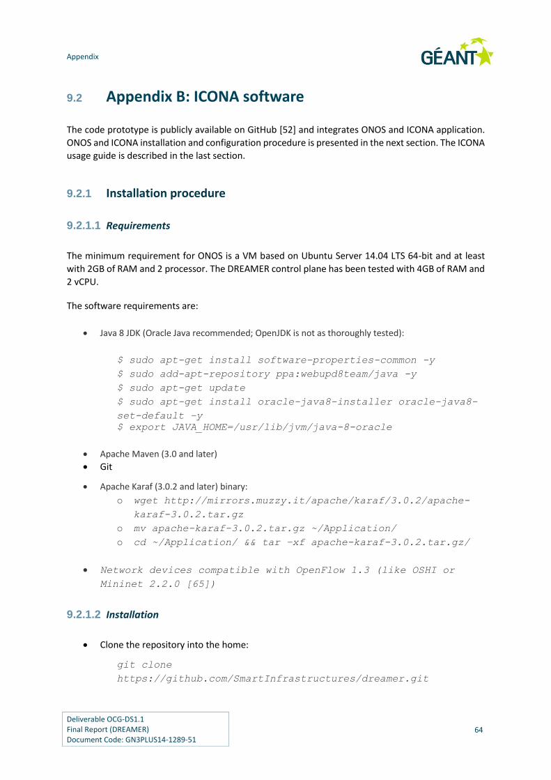
Appendix
Deliverable OCG-DS1.1 Final Report (DREAMER) Document Code: GN3PLUS14-1289-51
64
9.2 Appendix B: ICONA software
The code prototype is publicly available on GitHub [52] and integrates ONOS and ICONA application.
ONOS and ICONA installation and configuration procedure is presented in the next section. The ICONA
usage guide is described in the last section.
9.2.1 Installation procedure
9.2.1.1 Requirements
The minimum requirement for ONOS is a VM based on Ubuntu Server 14.04 LTS 64-bit and at least
with 2GB of RAM and 2 processor. The DREAMER control plane has been tested with 4GB of RAM and
2 vCPU.
The software requirements are:
Java 8 JDK (Oracle Java recommended; OpenJDK is not as thoroughly tested):
$ sudo apt-get install software-properties-common -y
$ sudo add-apt-repository ppa:webupd8team/java -y
$ sudo apt-get update
$ sudo apt-get install oracle-java8-installer oracle-java8-
set-default –y
$ export JAVA_HOME=/usr/lib/jvm/java-8-oracle
Apache Maven (3.0 and later)
Git
Apache Karaf (3.0.2 and later) binary:
o wget http://mirrors.muzzy.it/apache/karaf/3.0.2/apache-
karaf-3.0.2.tar.gz
o mv apache-karaf-3.0.2.tar.gz ~/Application/
o cd ~/Application/ && tar –xf apache-karaf-3.0.2.tar.gz/
Network devices compatible with OpenFlow 1.3 (like OSHI or
Mininet 2.2.0 [65])
9.2.1.2 Installation
Clone the repository into the home:
git clone
https://github.com/SmartInfrastructures/dreamer.git
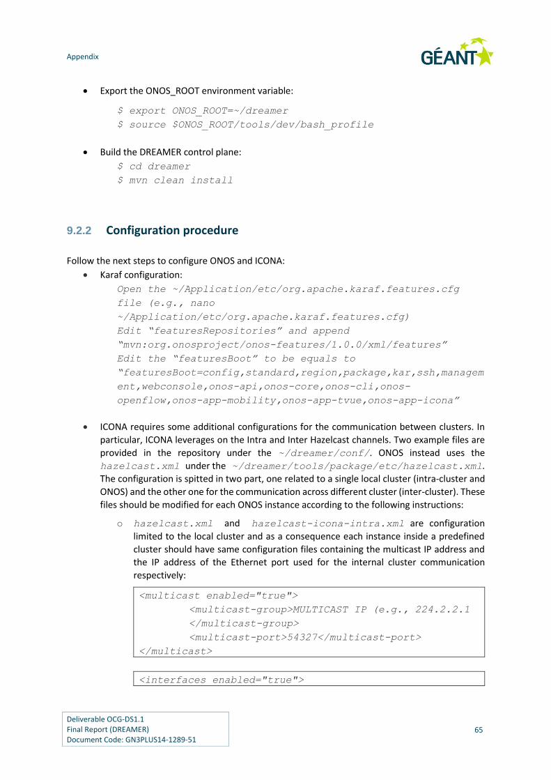
Appendix
Deliverable OCG-DS1.1 Final Report (DREAMER) Document Code: GN3PLUS14-1289-51
65
Export the ONOS_ROOT environment variable:
$ export ONOS_ROOT=~/dreamer
$ source $ONOS_ROOT/tools/dev/bash_profile
Build the DREAMER control plane:
$ cd dreamer
$ mvn clean install
9.2.2 Configuration procedure
Follow the next steps to configure ONOS and ICONA:
Karaf configuration:
Open the ~/Application/etc/org.apache.karaf.features.cfg
file (e.g., nano
~/Application/etc/org.apache.karaf.features.cfg)
Edit “featuresRepositories” and append
“mvn:org.onosproject/onos-features/1.0.0/xml/features”
Edit the “featuresBoot” to be equals to
“featuresBoot=config,standard,region,package,kar,ssh,managem
ent,webconsole,onos-api,onos-core,onos-cli,onos-
openflow,onos-app-mobility,onos-app-tvue,onos-app-icona”
ICONA requires some additional configurations for the communication between clusters. In
particular, ICONA leverages on the Intra and Inter Hazelcast channels. Two example files are
provided in the repository under the ~/dreamer/conf/. ONOS instead uses the
hazelcast.xml under the ~/dreamer/tools/package/etc/hazelcast.xml.
The configuration is spitted in two part, one related to a single local cluster (intra-cluster and
ONOS) and the other one for the communication across different cluster (inter-cluster). These
files should be modified for each ONOS instance according to the following instructions:
o hazelcast.xml and hazelcast-icona-intra.xml are configuration
limited to the local cluster and as a consequence each instance inside a predefined
cluster should have same configuration files containing the multicast IP address and
the IP address of the Ethernet port used for the internal cluster communication
respectively:
<multicast enabled="true">
<multicast-group>MULTICAST IP (e.g., 224.2.2.1
</multicast-group>
<multicast-port>54327</multicast-port>
</multicast>
<interfaces enabled="true">

Appendix
Deliverable OCG-DS1.1 Final Report (DREAMER) Document Code: GN3PLUS14-1289-51
66
<interface>IP ADDRESS OF ETHERNET
PORT (e.g., 10.216.160.*) </interface>
</interfaces>
hazelcast.xml and hazelcast-icona-intra.xml should have different
multicast IP addresses.
o hazelcast-icona-inter.xml configures the communication with different
clusters across geographical locations. As a consequence the multicast IP address
should be equal across all the ONOS instances also belonging to different clusters. An
IP address of interface permitting the communication with different clusters should
be indicate as aforementioned.
After the modification of files, run the following commands:
$ cp ~/dreamer/tools/package/etc/hazelcast.xml
~/Applications/apache-karaf-3.0.2/etc/
$ cp ~/dreamer/conf/hazelcast-icona-*.xml
~/Applications/apache-karaf-3.0.2/conf/
ONOS, and sub sequentially ICONA, requires network devices to point to multiple controller
instances belonging to the same cluster. OpenFlow devices support natively multiple
controllers per device. We tested our prototype against Open vSwitch, that can be configured
adding the following command:
$ sudo ovs-vsctl set-controller SWITCH-NAME tcp:CTL-
IP:CTL-PORT tcp:CTL-IP:CTL-PORT
9.2.3 Running procedure
The ICONA application developed on top of ONOS permits to:
1. Discovery, share and update the geographical topology.
2. Install Ethernet pseudo wire exploiting the usage of MPLS-Label switched path between end-
points.
After the installation procedure, run this command in each VM to launch ONOS that will automatically
load also ICONA on top of each instance:
$ karaf clean
It is possible to verify the expected behaviour of all the components retrieving the status of the
modules with the command on the ONOS console:
onos> bundle:list
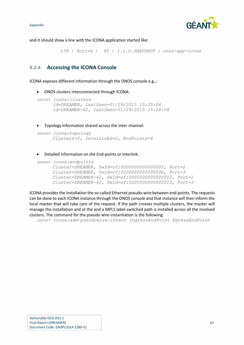
Appendix
Deliverable OCG-DS1.1 Final Report (DREAMER) Document Code: GN3PLUS14-1289-51
67
and it should show a line with the ICONA application started like:
139 | Active | 80 | 1.1.0.SNAPSHOT | onos-app-icona
9.2.4 Accessing the ICONA Console
ICONA exposes different information through the ONOS console e.g.,:
ONOS clusters interconnected through ICONA:
onos> icona:clusters
id=DREAMER, lastSeen=01/29/2015 15:25:04
id=DREAMER-42, lastSeen=01/29/2015 15:28:04
Topology information shared across the inter-channel:
onos> icona:topology
Clusters=2, InterLinks=2, EndPoints=4
Detailed information on the End-points or Interlink:
onos> icona:endpoints
Cluster=DREAMER, SwId=of:000000000000000f, Port=2
Cluster=DREAMER, SwId=of:000000000000000b, Port=3
Cluster=DREAMER-42, SwId=of:0000000000000012, Port=1
Cluster=DREAMER-42, SwId=of:0000000000000013, Port=3
ICONA provides the installation the so-called Ethernet pseudo-wire between end-points. The requests can be done to each ICONA instance through the ONOS console and that instance will then inform the local master that will take care of the request. If the path crosses multiple clusters, the master will manage the installation and at the end a MPLS label-switched path is installed across all the involved clusters. The command for the pseudo wire instantiation is the following:
onos> icona:add-pseudowire-intent IngressEndPoint EgressEndPoint
Appendix
Deliverable OCG-DS1.1 Final Report (DREAMER) Document Code: GN3PLUS14-1289-51
68
9.3 Appendix C: Mantoo
Mantoo [69] is a project meant to support SDN experiments over emulators and distributed testbeds.
Mantoo is able to drive and help the experimenters in the three phases that compose an experiment:
design, deployment and control. Mantoo includes an extensible web-based graphical topology
designer providing different layered network “views” (e.g. physical interconnections, control
relationships with SDN controllers, end-to-end service relationships among nodes). The framework is
able to validate a topology against a configurable set of constraints and then to automatically deploy
the topology over a Mininet emulator or a distributed SDN testbed, like Ofelia and the Géant
OpenFlow Facility. Mantoo offers the ability to access nodes by opening consoles directly via the web
GUI. Finally, Mantoo provides tools for evaluating the performance of the deployed solution [74].
Mantoo includes the Topology 3D, in fact it allows to design an OSHI network topology (both aspects
of the data plane and of the control plane) and to plan also the services, which have to be guaranteed
for the CEs. The topologies are exported in JSON format, and the project Dreamer-Topology-Parser-
And-Validator [70] provides the parsing functionality needed by the Topology Deployer project.
The code related to the Mantoo project can be downloaded from a public repository on github [69].
The latest version released is the v1.0-beta. Currently, it includes the support for the Mininet
emulation environment. The repository includes a README file, where we explain how to install the
components of the Mantoo project and deploy it on a server. A how-to is available at [73], providing
a walkthrough on the core functionality of the project.

Appendix
Deliverable OCG-DS1.1 Final Report (DREAMER) Document Code: GN3PLUS14-1289-51
69
9.4 Appendix D: Topology Deployer
In the current release of the Mantoo project is not possible to realize the deployment over distributed
testbeds, the support will be added in the next releases, so the Topology Deployer project has a key
role in the OSHI experiments over the distributed testbeds. It is composed by python modules that
are able to automatically produce the configuration files necessary for emulating a given topology,
composed of access and core OSHI nodes (OSHI-PE and OSHI-CR) and of CE routers. This includes the
automatic configuration of IP addresses, of dynamic routing (OSPF daemons), and of VXLAN/OpenVPN
tunnels in all nodes, therefore it relieves the experimenter from a huge configuration effort.
The configuration files generated by the deployer have to been uploaded on a site reachable from the
testbed or uploaded in each VMs belonging to the experiment. In order to realize the designed
topology we have to provide for each machine the private configuration files and then run the config
script (it is part of Dreamer-Setup-Scripts project). The automatic deployment is realized through the
Management Scripts (They also part of the project Dreamer-Setup-Scripts), that are able to download
the configuration files for all the testbed machines at once and execute the config script. The complete
procedure has been described in [67].
The code related to the Topology Deployer is collect under the repository called Dreamer-Testbed-
Deployer, and it can be downloaded from our public git repository [71]. The last version released is
the v1.1-beta. It includes scripts to automatically generate the configuration files for the Dreamer –
Setup – Scripts project, in particular the code released contains:
i) the automated generation of OSHI experiments configuration files (they include also
the configuration of the CEs and OpenFlow controllers);
ii) the automated generation of Plain IP router experiments configuration files (they
include also the configuration of the End points);
iii) the automated generation of the configuration of the layer 2 topology based on UDP
tunnels (VXLAN or OpenVPN).
As for instructions, the project has a README file, moreover we have realized also a how-to [72], that
explains step by step how to run the project in order to generate the configuration files of a given
topology.

Deliverable OCG-DS1.1 Final Report (DREAMER) Document Code: GN3PLUS14-1289-51
70
References
[1] The pan European NREN backbone.
http://www.geant.net/Network/The_Network/Pages/default.aspx
[2] ONOS - Open Network Operating System, http://onosproject.org/
[3] ON.LAB, the Open Networking Lab, http://onlab.us
[4] “ON.Lab Launches Revolutionary SDN Open Source Network Operating System — ONOS™
— on behalf of its Community of Service Providers and Innovator Partners”,
http://onosproject.org/2014/11/04/onlab-launches-onos-operating-system/
[5] X. Jeannin, T. Szewczyk, "GN3Plus SA3T3 - Multi Domain VPN - technical architecture",
2nd TERENA Network Architects Workshop(Prague) – 14th Nov. 2013 -
http://www.terena.org/activities/netarch/ws2/programme2.html
[6] GÉANT network topology,
http://geant3.archive.geant.net/Network/NetworkTopology/pages/home.aspx
[7] Sachin Sharma, Dimitri Staessens, Didier Colle, Mario Pickavet, Piet Demeester,
OpenFlow: Meeting Carrier-Grade Requirements, Computer Communications, Volume
36, Issue 6, 15 March 2013, Pages 656–665S.
[8] A. Hecker, “Carrier SDN: Security and Resilience Requirements”, VDE/ITG Working Group
5.2.4, 12th WorkShop,, 5 Nov 2013, München
[9] Wedge Greene & Barbara Lancaster, “Carrier-Grade: Five Nines, the Myth and the Reality
Pipeline”, Volume 3, Issue 11 2006, http://www.pipelinepub.com
[10] Carrier Grade Linux workgroup, Carrier Grade Linux Requirements Definition, Version 5.0,
March 2011, http://www.linuxfoundation.org/collaborate/workgroups/cgl/group
[11] S. Vissicchio et al: “Safe Update of Hybrid SDN Networks” – Public Technical Report
http://hdl.handle.net/2078.1/134360
[12] “Software-Defined Networking: The New Norm for Networks”, ONF White Paper, April
13, 2012
[13] S. Salsano, P. L. Ventre, L. Prete, G. Siracusano, M. Gerola, E. Salvadori, “Open Source
Hybrid IP/SDN networking (and its emulation on Mininet and on distributed SDN
testbeds)”, EWSDN 2014, 1-3 September 2014, Budapest, Hungary
[14] S. Vissicchio et al., “Opportunities and Research Challenges of Hybrid Software Defined
Networks”, ACM SIGCOMM Computer Communications Review, Editorial Zone (April
2014).
[15] C. Rothenberg et al. “Revisiting routing control platforms with the eyes and muscles of
software-defined networking”, HotSDN'12 Workshop, Aug. 2012

References
Deliverable OCG-DS1.1 Final Report (DREAMER) Document Code: GN3PLUS14-1289-51
71
[16] J. Kempf, et al “OpenFlow MPLS and the open source label switched router”. In proc. of
the 23rd ITC, 2011
[17] M. R. Nascimento et al., “Virtual routers as a service: the Routeflow approach leveraging
software-defined networks”. 6th International Conference on Future Internet
Technologies, CFI 2011.
[18] Open Networking Foundation (ONF) “OpenFlow Switch Specification” Version 1.4.0 (Wire
Protocol 0x05) October, 2013
[19] S. Jain, et al, “B4: Experience with a Globally-Deployed Software Defined WAN” in
SIGCOMM, 2013
[20] Marc Suñé et al., “Design and implementation of the OFELIA FP7 facility: The European
OpenFlow testbed”, Computer Networks, Vol. 61, March 2014
[21] Mark Berman et al., “GENI: A federated testbed for innovative network experiments”,
Computer Networks, Vol. 61, March 2014
[22] Internet2 Layer 2 Services
http://www.internet2.edu/products-services/advanced-networking/layer-2-
services/#service-features
[23] Internet2 Software Defined Networking Group homepage
http://www.internet2.edu/communities-groups/advanced-networking-groups/software-
defined-networking-group/
[24] TREEHOUSE, an international research network for SDN
[25] Networkx homepage - http://networkx.github.io/
[26] OSHI homepage http://netgroup.uniroma2.it/OSHI
[27] P. L. Ventre et al. “OSHI technical report”, http://netgroup.uniroma2.it/TR/OSHI.pdf and
available at [26]
[28] Floodlight’s home page - http://www.projectfloodlight.org
[29] Open vSwitch home page - http://openvswitch.org/
[30] Quagga homepage - http://www.nongnu.org/quagga/
[31] J Pettit, E. Lopez, “OpenStack: OVS Deep Dive”, Nov 13 2013,
http://openvswitch.org/slides/OpenStack-131107.pdf
[32] M. Mahalingam et al. “VXLAN: A Framework for Overlaying Virtualized Layer 2 Networks
over Layer 3 Networks”, draft-mahalingam-dutt-dcops-vxlan-09.txt, April 10, 2014
[33] C. Filsfils, S. Previdi, (Eds.) et al. “Segment Routing Architecture”, draft-ietf-spring-
segment-routing-01, Feb 2015
[34] E. Rosen et al., “MPLS Label Stack Encoding”, IETF RFC 3032
[35] S. Bryant, P. Pate, “Pseudo Wire Emulation Edge-to-Edge (PWE3) Architecture”, IETF RFC
3985
[36] J. Medved, A. McLachlan, D. Meyer, “MPLS-TP Pseudowire Configuration using OpenFlow
1.3” draft-medved-pwe3-of-config-01
[37] VPLS, RFC 4761 – https://tools.ietf.org/html/rfc4761
[38] RYU homepage – http://osrg.github.io/ryu/
[39] Steiner tree – http://mathworld.wolfram.com/SteinerTree.html
[40] L. Kou et al., “A Fast Algorithm for Steiner Trees”
References
Deliverable OCG-DS1.1 Final Report (DREAMER) Document Code: GN3PLUS14-1289-51
72
[41] GOFF homepage – https://openflow.geant.net/#
[42] Zabbix homepage - http://www.zabbix.com/
[43] Teemu Koponen, Martin Casado, Natasha Gude, Jeremy Stribling, Leon Poutievski, Min
Zhu, Rajiv Ramanathan, Yuichiro Iwata, Hiroaki Inoue, Takayuki Hama, and Scott Shenker.
Onix: A distributed control platform for large-scale production networks. In Proceedings
of the 9th USENIX Conference on Operating Systems Design and Implementation, 2010.
[44] Y.Ganjali H. Y. Soheil. Kandoo: a framework for efficient and scalable offloading of control
applications. In HotSDN 2012.
[45] Y. Ganjali A. Tootoonchian. Hyperflow: a distributed control plane for OpenFlow. In 2010
internet network management conference on Research on enterprise networking, pp. 3-
3, 2013.
[46] K. Phemius, M. Bouet, and J. Leguay. Disco: Distributed sdn controllers in a multi-domain
environment. In NOMS 2014.
[47] AA Dixit et al. ElastiCon: an elastic distributed sdn controller. Proceedings of the tenth
ACM/IEEE symposium on Architectures for networking and communications systems,
2014.
[48] A Krishnamurthy et al. Pratyaastha: an efficient elastic distributed sdn control plane.
Proceedings of the third workshop on Hot topics in in software defined networking 2014
[49] S Matsumoto et al. Fleet: defending SDNs from malicious administrators. Proceedings of
the third workshop on Hot topics in software defined networking, 2014
[50] P. Berde et al. ONOS: towards an open, distributed SDN OS. Proceedings of the third
workshop on Hot topics in software defined networking, 2014
[51] B. Heller et al. The Controller Placement Problem. Proceedings of the first workshop on
Hot topics in software defined networking, 2012
[52] ICONA software. https://github.com/SmartInfrastructures/dreamer
[53] ONOS web-site. http://onosproject.org/
[54] Apache Karaf. http://karaf.apache.org/
[55] Hazelcast web-site. http://www.hazelcast.com
[56] Netem web-site. http://www.linuxfoundation.org/collaborate/
workgroups/networking/netem
[57] AD Ferguson et al. Participatory networking: An API for application control of SDNs. ACM
SIGCOMM Computer Communication Review, 2013
[58] M Canini et al. A Distributed and Robust SDN Control Plane for Transactional Network
Updates. The 34th Annual IEEE International Conference on Computer Communications
(INFOCOM 2015)
[59] F Botelho et al. SMaRtLight: A Practical Fault-Tolerant SDN Controller. ArXiv preprint
arXiv:1407.6062, 2014.
[60] V Yazici et al. Controlling a software-defined network via distributed controllers. ArXiv
preprint arXiv:1401.7651, 2014
[61] OpenDaylight - http://www.opendaylight.org/
[62] Akka framework - http://akka.io/
[63] Raft consensus algorithm - http://en.wikipedia.org/wiki/Raft_%28computer_science%29
[64] Apache 2.0 license – http://www.apache.org/licenses/LICENSE-2.0

References
Deliverable OCG-DS1.1 Final Report (DREAMER) Document Code: GN3PLUS14-1289-51
73
[65] Mininet - http://mininet.org/
[66] Dreamer – Setup – Scripts – https://github.com/netgroup/Dreamer-Setup-Scripts
[67] OSHI (Open Source Hybrid IP/SDN) Experiment over the OFELIA SDN TESTBED –
http://netgroup.uniroma2.it/twiki/pub/Oshi/WebHome/ofelia-experiment.pdf
[68] OSHI VM -
https://mega.co.nz/#!jIxTWaAS!pP1ZHDmntjyzxpFH9Do4FkJSPL5V6on9pKislunGdMA
[69] DREAMER Mantoo repository- https://github.com/netgroup/Dreamer-Mantoo
[70] DREAMER Topology Parser And Validator repository-
https://github.com/netgroup/Dreamer-Topology-Parser-and-Validator
[71] DREAMER Testbed Deployer repository - https://github.com/netgroup/Dreamer-Testbed-
Deployer
[72] DREAMER Testbed Deployer how to
http://netgroup.uniroma2.it/twiki/bin/view/Oshi/OshiExperimentsHowto#TestbedDeplo
yer
[73] DREAMER Mantoo and Topology 3D how-to
http://netgroup.uniroma2.it/twiki/bin/view/Oshi/OshiExperimentsHowto#ManToo
[74] Dreamer Measurement Tools repository – https://github.com/netgroup/Dreamer-
Measurements-Tools

Deliverable OCG-DS1.1 Final Report (DREAMER) Document Code: GN3PLUS14-1289-51
74
Glossary
ACE ACcess Encapsulator
BIL Backup Inter cluster Link
CE Customer Edge
CLI Command Line Interface
CR Core Router
DSH Distributed SHell
EoMPLS Ethernet over MPLS
EP End Point
GOFF GÉANT OpenFlow Facility
ICONA Inter Cluster ONos Application
IL Inter cluster Link
IP FE IP Forwarding Engine
IPoMPLS IP over MPLS
JMS Java Messaging System
LME Local Management Entity
LSP Label Switched Path
Mantoo Management tools
MT Measurement Tools
NIB Network Information Base
NOS Network Operating System
NREN National Research and Education Network
OCF OFELIA Control Framework
OF OpenFlow
OFCS OpenFlow Capable Switch
ONOS Open Networking Operating System
OSHI Open Source Hybrid Ip/sdn
OVS Open vSwitch
PE Provider Edge
PW Pseudo Wire
PWE3 Pseudo Wire Emulation Edge
SBP SDN Base Path
SDN Software Defined Networking
SM Service Manager
TM Topology Manager
Topology 3D Topology and Service Design, Deploy, Direct
Glossary
Deliverable OCG-DS1.1 Final Report (DREAMER) Document Code: GN3PLUS14-1289-51
75
VBP VSS Bridging Point
VLL Virtual Leased Line
VPLS Virtual Private Lan Service
VSS Virtual Switch Service
VTEP Virtual Tunnel End Point

Deliverable OCG-DS1.1 Final Report (DREAMER) Document Code: GN3PLUS14-1289-51
76
Acknowledgements
We would like to thank the GÉANT technical coordinator for DREAMER, Milosz Przywecki for his
continuous and valuable supervision to the project activities and his precious revisions and
suggestions in the preparation of milestone documents and of this deliverable.
We also thank the GÉANT technical staff that supported our experimental activities on the GÉANT
testbeds.
Finally the project leader would like to thank the GÉANT Open Call administration staff for their
availability and their professional support in the lifetime of the project.