Final Presentation Group 16 Mike Orr Loc Truong Dang Khoa Le.
39
SmartWalker Final Presentation Group 16 Mike Orr Loc Truong Dang Khoa Le
-
Upload
penelope-garrison -
Category
Documents
-
view
213 -
download
0
Transcript of Final Presentation Group 16 Mike Orr Loc Truong Dang Khoa Le.

SmartWalkerFinal Presentation
Group 16Mike Orr
Loc TruongDang Khoa Le

SmartWalker Mechanical
Brake
Camera
Electronics

Interested in robotics and wireless control
To create a useful product◦ Help the elderly and/or disabled
Motivation

Assist in day-to-day activity of user
Durable◦ Battery over-charging protection
Low cost
Goals and Objectives

Weight less than 50 pounds Be able to support up to 200 pounds of
weight (manual) Travel no faster than 3 miles per hour Have no more than a 2 second delay in video
streaming and control Be able sustain functionality up to 40 meters
away from the walker Be able to sustain functionality for up to 2
hours without recharging (non-continuous use)
Specifications

Overall System Block Diagrams

Remote Controller
Remote Controller
2” color display
DPDTSwitches
2.4 GHzVideo
Receiver
433 MHzRF
Transmitter
HT12E4 ChannelEncoder
Receiver

Receiver
Receiver
2.4 GHzVideo
Transmitter
433 MHzRF Receiver
HT12D4 ChannelDecoder
L293DDual H-bridge Motor Driver
M1
M2RemoteController

Task Distribution

Remote Control Schematic

Receiver Schematic

Sub-systems

Motors and Motor Controller
Motor Controller
Left Motor
Right Motor

Using Bridge Motor Drive L293D (16 PIN chip)
Cost : $2.50. Used for DC or Stepper Motor
Motor Controller
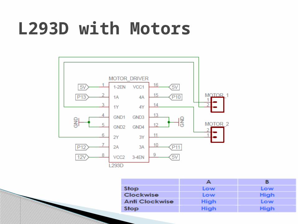
L293D with Motors

Forward and Backward Turning left and right
Driving Method

Produce high torque Have reasonable turn speed Require 12V DC (to be compatible with
system voltage supplier) Generates low current to reduce heat Low cost
Specifications desired for motors

Motor Names
Voltage(V)
Current(A)
Torque(N*m)
RPM Cost(USD/piece)
Electric Gear Motor
12 3-15 11.5 50 59.99
63ZYT01C DC Motor
24 4.5 1.3 2800 18
Leeson M1135246
12 0.23 17.51 83 347
Motor Choices (DC Motor)

ON/OFF switch Momentary switch
Latch Switch
Voltage source 12 V 12 V 12 V
Current rating 15 A 3 A 3 A
Control method On - Off Hold right : turnRelease : stopHold left : turn
opposite directionRelease : stop
Press right : turnPress right : stopPress left : turn
opposite directionPress left : stop
Motor control options :

L293D Motor Driver
Electric Gear
Motor(Left)
Electric Gear
Motor(Right)
Motor Parts

Motors connect to small discs.
Pulleys connects to the fixed-wheels using low-tension belts.
Small pins are used switch from remote control to manual use.
When using remote, the pins will connect the motors to the plastic pulleys.
Motor – Wheels connection

433MHz RF ModulesParameters Transmitter Receiver
Operating Voltage 3V-12V 5V (±0.5V)
Operating Current 40mA (12V)9 mA (3V) 5.5mA (5V)
Modulation Mode ASK/OOK OOK/ASK
Frequency 315MHz -433.9 MHz 315MHz-433.9MHz
Transmission Power 25mW (315MHZ at 12V) ---
Operating Range 120ft (clear of obstructions) same
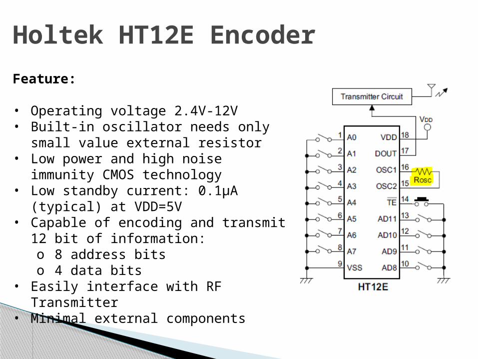
Holtek HT12E Encoder
Feature:
• Operating voltage 2.4V-12V • Built-in oscillator needs only small
value external resistor• Low power and high noise immunity
CMOS technology• Low standby current: 0.1µA (typical)
at VDD=5V• Capable of encoding and transmit 12
bit of information:o 8 address bitso 4 data bits
• Easily interface with RF Transmitter• Minimal external components
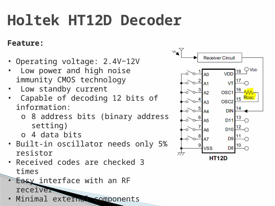
Holtek HT12D DecoderFeature:
• Operating voltage: 2.4V~12V• Low power and high noise immunity
CMOS technology• Low standby current• Capable of decoding 12 bits of
information:o 8 address bits (binary address
setting)o 4 data bits
• Built-in oscillator needs only 5% resistor• Received codes are checked 3 times• Easy interface with an RF receiver• Minimal external components
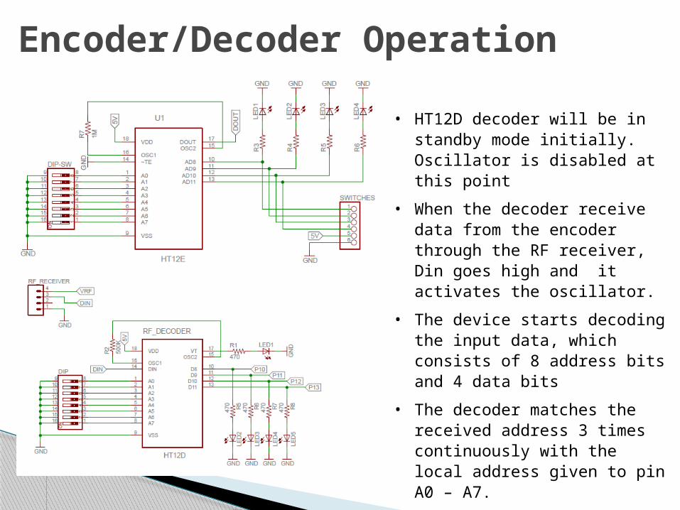
• HT12D decoder will be in standby mode initially. Oscillator is disabled at this point
• When the decoder receive data from the encoder through the RF receiver, Din goes high and it activates the oscillator.
• The device starts decoding the input data, which consists of 8 address bits and 4 data bits
• The decoder matches the received address 3 times continuously with the local address given to pin A0 – A7.
• Once confirmed, the data bits are decoded and activates 4 output pins D8-D11.
Encoder/Decoder Operation

Control Switches
Motion
L293D Output Terminals ( Motor Input Terminals)
+ Motor 1 - Motor 1 + Motor 2 - Motor 2
Forward 1 0 0 1
Reverse 0 1 1 0
Left 0 0 0 1
Right 1 0 0 0
Stop 0 0 0 0
• Rotation of the motor changes by switching its polarity• To switch/control the polarity of the motors from the
remote controller, 2 DPDT switches are used

Control Switches

Foscam FI9821W◦ HD Quality, 1280x 720 Resolution◦ High Cost
TENVIS JPT3815W◦ Lesser Quality◦ Good Pricing
Q-SEE Security Camera◦ Good Quality◦ RCA Compatible◦ Free of Charge (Loc)
Camera

2.4 GHz Wireless Video/Audio Module◦ 9 Volts◦ Max Current:
180mA (Receiver) 30mA (Transmitter)
◦ Frequency: 2.4 GHz◦ RCA Connectors
Video Transmitter/Receiver

Power System-Block Diagram
UA7805Regulator
9VBattery
Remote Controller Block DiagramPowerControlVideo
DPDTSwitches
2.4 GHzVideo
Receiver
433 MHzRF
Transmitter
HT12E4 ChannelEncoder
2” color display

Power System-Block Diagram
12VBattery
Receiver Block Diagram
Regulator(5V)
PowerControlVideo
2.4 GHzVideo
Transmitter
433 MHzRF Receiver
HT12D4 ChannelDecoder
L293DDual H-bridge Motor Driver
M1
M2

3 options:
◦ HitLights Rechargeable 3800mAh Lithium Ion Battery Pack
◦ Pitsco TETRIX 12-Volt Rechargeable NiMH Battery Pack and Charger
◦ NiMH Battery Pack: Customize 12V 5000mAh
Battery

μA7805CKC◦ Internal Thermal-Overload Protection◦ High Power-Dissipation Capability
LM7809◦ Short Circuit Protection◦ Thermal Overload Protection
Regulators

Power ConsumptionDevice Voltage (V) Current (mA) Power (mW)HT12E 5 5 25HT12D 5 5 25
RF Receiver 5 5 25RF Transmitter 5 5 25
L293D (1) - chip 5 0.1 0.5L293D (2) - chip 5 0.1 0.5
Left Motor 12 2400 28800Right Motor 12 2400 28800
Video Transmitter 9 30 270
Video Receiver 9 30 270Camera 12 600 7200
Video Display 9 216 1944
Total Power: 67.385 Watts

Battery Life Calculation
3800----------------------------
5696.2
0.467 Hours*
*calculated for all components running constantly at maximum ratings

Power◦ Constant running motor◦ Varying on/off
Max Weight Supported◦ Driving – 25 pounds◦ Stationary – 200 pounds
Speed (Max vs Avg)◦ Max < 3 MPH◦ Avg = 0.77 MPH
Video – tested at subsystem level
Testing

Thermal Issues◦ Motor Driver reaching thermal threshold
Use 12V relays to drive motors
Mechanical Issues◦ Platform causes stability issues◦ Wheel drive limits weight support capability
Redo platform
Antenna◦ Limits transmission range
Need longer antenna
Current Issues/Solutions

BudgetItem Unit Price Ordered Price
Video Transmitter/Receiver $32.00 1 $32.00
RF Transmitter/Receiver $4.12 1 $4.12HT12D/HT12E 1 $0.00UA7805CKCS $0.49 1 $0.49LM7809 $0.67 1 $0.67
Pitsco TETRIX 12-Volt Rechargeable NiMH Battery Pack and Charger $84.90 1 $84.90Video Display $42.31 1 $42.31
22 pF capacitor (30pk) $2.43 1 $2.43
QSEE Security Camera FREE 1 $0.00
Wondermotor 12V DC Gear Motor $59.99 2 $119.98L293D $2.50 2 $5.00DPDT Switches $5.00 2 $10.00PCB $48.36 2 $96.72
Miscellaneous (bolts, screws, welding etc) $100.00 1 $100.00
Total $498.62

Questions?

![DQcl~p - TI]' HOktkthcm.edu.vn/./uploads/files/Mon_Chinh_tri_Coso... · 2017-07-01 · cua Hieu truong Truong Cao dAng Kinh d-Ky thudt Thanh pho H6 Chi Minh) STT MiiSV HQd~m Ten Lop](https://static.fdocuments.net/doc/165x107/5e257831d08e44357d2b7479/dqclp-ti-2017-07-01-cua-hieu-truong-truong-cao-dang-kinh-d-ky-thudt-thanh.jpg)