FINAL Geotechnical Engineering Report Northcreek Road ... GEOTECHNICAL Report_217-112...exploration...
33
FINAL Geotechnical Engineering Report Northcreek Road Culverts Replacement Beulah, Pueblo County, Colorado Yeh Project No.: 217-112 October 9, 2017 Prepared for: Wilson & Company, Inc. Attn: Don Garcia, P.E. 5755 Mark Dabling Blvd., Suite #220 Colorado Springs, CO 80919 Prepared by: Yeh and Associates, Inc. 627 Elkton Dr. Colorado Springs, CO 80907 Phone: 719-434-1643
Transcript of FINAL Geotechnical Engineering Report Northcreek Road ... GEOTECHNICAL Report_217-112...exploration...
FINAL
Geotechnical Engineering Report
Northcreek Road Culverts Replacement
Beulah, Pueblo County, Colorado
Yeh Project No.: 217-112
October 9, 2017
Prepared for:
Wilson & Company, Inc. Attn: Don Garcia, P.E.
5755 Mark Dabling Blvd., Suite #220 Colorado Springs, CO 80919
Prepared by:
Yeh and Associates, Inc. 627 Elkton Dr.
Colorado Springs, CO 80907
Phone: 719-434-1643
FINAL
Geotechnical Engineering Report
Northcreek Road Culverts Replacement
Beulah, Pueblo County, Colorado
Yeh Project No.: 217-112
October 9, 2017
Prepared by: Reviewed by: Hai Ming Lim, P.E. Hsing-Cheng Liu, P.E., Ph.D. Project Manager Senior Project Manager
Independent Reviewer: Michael L. Kiefer, P.E. Senior Project Manager
10-9-17
i
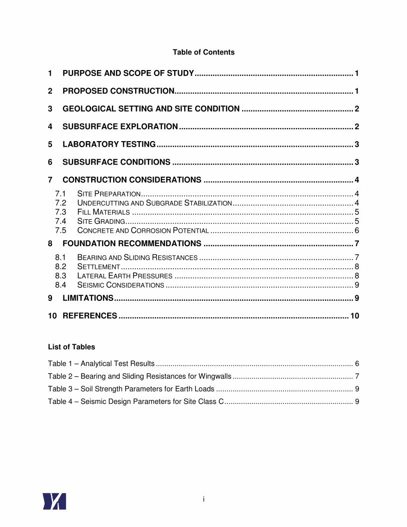
Table of Contents
1 PURPOSE AND SCOPE OF STUDY ....................................................................... 1
2 PROPOSED CONSTRUCTION ................................................................................ 1
3 GEOLOGICAL SETTING AND SITE CONDITION .................................................. 2
4 SUBSURFACE EXPLORATION .............................................................................. 2
5 LABORATORY TESTING ........................................................................................ 3
6 SUBSURFACE CONDITIONS ................................................................................. 3
7 CONSTRUCTION CONSIDERATIONS ................................................................... 4
7.1 SITE PREPARATION ............................................................................................... 4
7.2 UNDERCUTTING AND SUBGRADE STABILIZATION ...................................................... 4
7.3 FILL MATERIALS ................................................................................................... 5
7.4 SITE GRADING ...................................................................................................... 5
7.5 CONCRETE AND CORROSION POTENTIAL ................................................................ 6
8 FOUNDATION RECOMMENDATIONS ................................................................... 7
8.1 BEARING AND SLIDING RESISTANCES ..................................................................... 7
8.2 SETTLEMENT ........................................................................................................ 8
8.3 LATERAL EARTH PRESSURES ................................................................................ 8
8.4 SEISMIC CONSIDERATIONS .................................................................................... 9
9 LIMITATIONS ........................................................................................................... 9
10 REFERENCES ....................................................................................................... 10
List of Tables
Table 1 – Analytical Test Results ............................................................................................... 6
Table 2 – Bearing and Sliding Resistances for Wingwalls .......................................................... 7
Table 3 – Soil Strength Parameters for Earth Loads .................................................................. 9
Table 4 – Seismic Design Parameters for Site Class C .............................................................. 9
ii
List of Figures
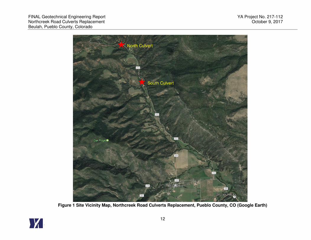
Figure 1 Site Vicinity Map, Northcreek Road Culverts Replacement, Pueblo County, CO
(Google Earth) ................................................................................................................. 122
Figure 2 Geologic Map of Area, Northcreek Road Culvert Replacement ................................. 133
List of Appendices
Appendix A. Boring Location Plans
Appendix B. Legend, Boring Logs and Laboratory Test Results
FINAL Geotechnical Engineering Report YA Project No. 217-112 Northcreek Road Culverts Replacement October 9, 2017 Beulah, Pueblo County, Colorado
1
1 PURPOSE AND SCOPE OF STUDY
This report presents the results of Yeh and Associates, Inc.’s (Yeh) geotechnical engineering
evaluation and geotechnical recommendations for the proposed two culverts replacement on
Northcreek Road in Beulah, Pueblo County, Colorado. The purpose of this report is to provide
geotechnical engineering recommendations for use by Wilson & Company, and Pueblo County
for the design and construction of the proposed culvert replacements. The subsurface
exploration and engineering evaluation were conducted in general accordance with the
Colorado Department of Transportation (CDOT) guidelines and American Association of State
Highway and Transportation Officials Seventh Edition, 2014 (AASHTO, 2014).
Our scope of services includes the following:
• Drilling 2 borings at each culvert replacement sites, for a total of 4 borings to obtain
subsurface information.
• Performing laboratory testing on select soil and bedrock samples collected during our
investigation.
• Preparing a report that summarizes the field and laboratory data, presents the results of
geotechnical engineering analyses for the design of concrete box culverts (CBC), and
provides geotechnical engineering recommendations.
2 PROPOSED CONSTRUCTION
It is our understanding that the existing culverts over North Creek were damaged in a 2015 flood
event, and were temporary repaired with 60 inch diameter corrugated steel pipes (CSP). Both
culverts are on Northcreek Road, with the north culvert approximately 0.9 miles north of the
south culvert. The proposed project is to replace both 60 inch CSPs with 8 feet wide by 8 feet
high CBCs as part of the Pueblo County Flood Recovery projects. Installation of bank
protection (e.g. rip rap) and replacement of the approach pavements at the box structures
(approximately 100 feet at each location) are also planned as part of the project. The
approximate location of the planned CBC are shown on Figure 1 and Boring Location Plans
presented in Appendix A.

FINAL Geotechnical Engineering Report YA Project No. 217-112 Northcreek Road Culverts Replacement October 9, 2017 Beulah, Pueblo County, Colorado
2
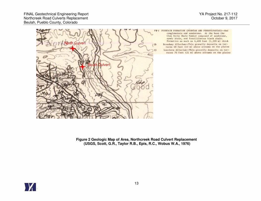
3 GEOLOGICAL SETTING AND SITE CONDITION
The project is located in the Fountain formation of Permian and Pennsylvanian age. The
Fountain formation is comprised of red conglomerate and sandstone. The Glen Eyrie Shale
member composed of sandstone, sandy shale, and fossiliferous black shale is present at the
base of the unit. The Fountain formation can be as much as 4,400 feet thick. A geologic map
of the project area is included in Figure 2.
The surficial soils at the proposed culverts locations are mapped by NRCS as Larkson series.
The Larkson series is comprised of sandy soils over heavy clayey soils. Based on subsurface
data obtained during this exploration, the subsurface soils at the proposed culvert locations
consist primarily of sandy soils that are underlain at varying depths by claystone and sandstone
bedrock. The subsurface materials encountered in the borings are generally consistent with the
surficial soils mapped by USGS and NRCS, except that the heavy clay soils were not
encountered in the borings.
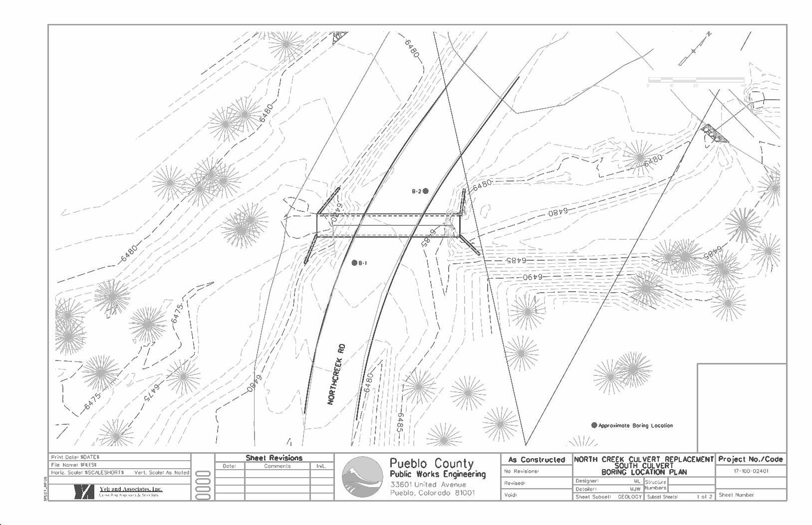
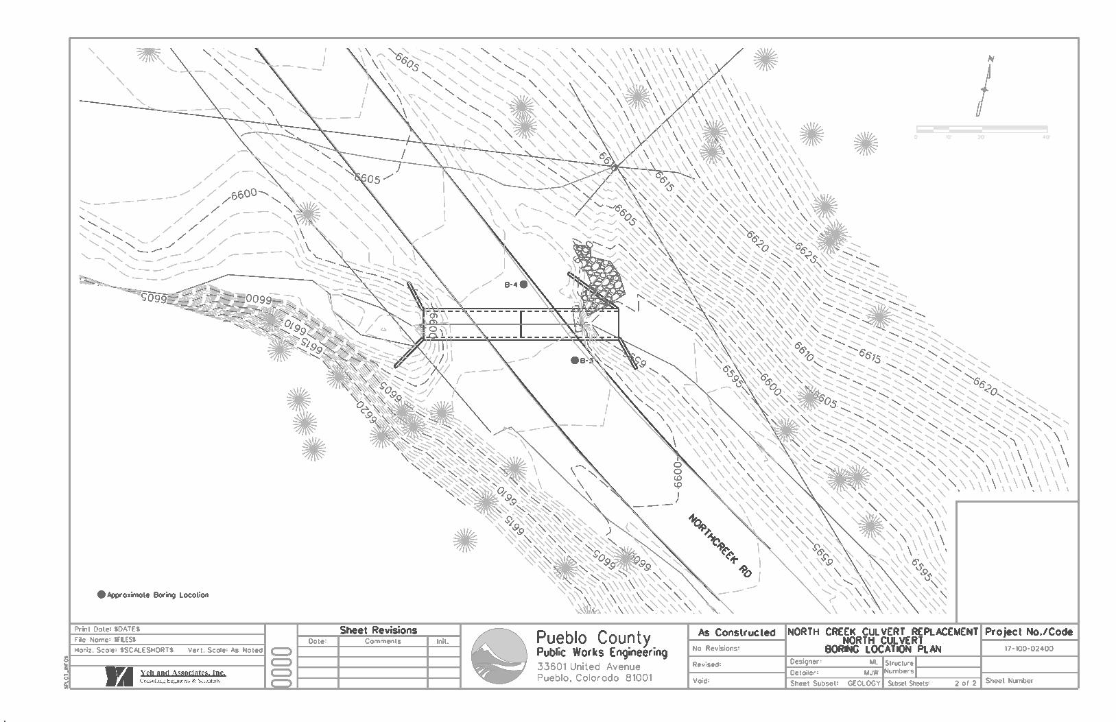
4 SUBSURFACE EXPLORATION
A total of four borings (YA-B-1 through YA-B-4) were drilled by Yeh at the locations of the
proposed culvert structures, with two borings generally drilled diagonally at each culvert
location. At the proposed northern culvert, the borings were drilled on the same side of the road
for traffic safety concerns. The boring locations are shown in on Figure 3 and 4, Boring Location
Plans presented in Appendix A. The locations of the borings were estimated based on the
distances measured from the existing CSPs. The locations and elevations of the existing
ground at the boring locations were not surveyed. The borings were drilled by Vine
Laboratories using drill rigs equipped with an automatic hammer and nominal 4-inch outside
diameter solid-stem augers as noted on the boring logs. Upon completion of drilling, the borings
were backfilled with drill cuttings and on-site soils. The subsurface conditions encountered in
the borings were logged by a representative of Yeh. The legends and borings logs are
presented in Appendix B.
Modified California (MC) tube samples were obtained during the Yeh site investigation. The MC
sampler is 12 inches in length with an inside diameter of 2.0 inches, an outside diameter of 2.5
inches, and uses 4-inch long brass liners to collect samples. The sampler was seated at the
bottom of the boring, then advanced by a 140 pound hammer falling a distance of 30 inches.
FINAL Geotechnical Engineering Report YA Project No. 217-112 Northcreek Road Culverts Replacement October 9, 2017 Beulah, Pueblo County, Colorado
3
The modified California penetration resistance value was recorded as the total number of blows
required to advance the sampler during the final two 6-inch intervals of drive penetration. If 50
blows could not advance the sampler in a 6-inch interval, driving was terminated.
5 LABORATORY TESTING
The samples collected during the subsurface investigation were transported to Yeh’s laboratory.
They were examined and a program of laboratory testing was developed to evaluate the
engineering properties of the collected subsurface materials. Selected soil samples were tested
to evaluate their engineering properties, using the following tests:
• natural moisture content
• grain size analysis
• Atterberg limits
• pH
• resistivity
• water soluble chlorides and sulfates
The test results are shown on the boring logs and are included in Appendix B. Following the
completion of the laboratory testing, the field descriptions were confirmed or modified as
necessary and boring logs were finalized.
6 SUBSURFACE CONDITIONS
Four borings were performed for the subsurface exploration, with 2 borings at each culvert
location. Based on the borings, the existing pavement is approximately 4” of asphalt over 2
inches of aggregate base course at the south culvert. The asphalt pavement at the north culvert
is approximately 3.5” thick, with approximately 2 inches of aggregate base course on the south
approach and no aggregate base course was encountered on the north approach. Fill materials
consisting of varying amounts of broken shale, clay, sand and gravel was encountered below
the pavement and extended to approximately 8 to 8.5 feet below the existing ground surface at
the south culvert, and to approximately 4.5 to 6 feet at the north culvert. Sand with varying
amounts of clay and gravel was encountered below the fill materials and extends to depths
ranging from approximately 11 to 21 feet below the existing ground surface. Claystone and
sandstone were encountered below the sand soils and extended to the terminated depths.

FINAL Geotechnical Engineering Report YA Project No. 217-112 Northcreek Road Culverts Replacement October 9, 2017 Beulah, Pueblo County, Colorado
4
Groundwater observations at the time of drilling were made and are shown on the boring logs.
Groundwater was encountered at approximate depths of 10 to 17 feet below the existing ground
surface at the end of drilling. Based on the site observation and features observed during field
explorations, the proposed culvert areas are also impacted by creek water. Depending on
foundation elevations, groundwater and surface water may be encountered during construction
and should be considered for the design. Groundwater and surface water variations can occur
during different seasons, following precipitation events, after site grading changes, and due to
changes in surface and subsurface drainage characteristics of the site and/or the surrounding
area. Year-round groundwater conditions were beyond the scope of this project.
7 CONSTRUCTION CONSIDERATIONS
7.1 Site Preparation
Subgrade to receive embankemnt fill should be prepared in accordance with Section 203 of
CDOT Standard Specifications. Initial sitework should consist of stripping organic materials or
other deleterious materials, and removing existing structures from areas of the proposed
construction. The exposed subgrade should be free of all organics, topsoil, debris, and loose or
soft material. Deleterious materials should be removed and stockpiled for future use in
proposed landscaped or non-structural areas. Areas to receive fill as part of the site grading
operations should be evaluated by the geotechnical engineer prior to the placement of any new
fill materials.
After stripping and over excavation, the exposed subgrade soils should be scarified to a
minimum of 12 inches at the channel bottom and in other areas (channel side slope, below
pavement), moisture conditioned, and recompacted according to Section 203.07 of the CDOT
Standard Specifications for Road and Bridge Construction, dated 2011.
7.2 Undercutting and Subgrade Stabilization
Based on the field observation, it is anticipated that the existing subsurface materials in the
creek channel may be wet and loose. Creek diversion and de-watering techniques may be
required for foundation subgrade preparation and general construction. If unstable conditions
are encountered or develop during construction, the existing subgrade could be undercut to firm
soil below the soft layer and replaced with properly compacted structural fill in accordance with
Section 7.3 of this report. Additionally, if isolated areas of deep soft soil are encountered,
FINAL Geotechnical Engineering Report YA Project No. 217-112 Northcreek Road Culverts Replacement October 9, 2017 Beulah, Pueblo County, Colorado
5
stabilization of the subgrade using geogrid is acceptable. In these isolated areas, the over-
excavation should extend to a depth of approximately 12 inches below the planned over-
excavation. After the over-exacavation, approximately 3 to 6 inches of aggregate base
materials should be placed at the bottom of the excavation and lightly compacted. A geogrid
should then be placed on top of this aggregate base layer. A minimum of 6 inches of aggregate
base should then be placed on top of the geogrid. The stabilized subgrade should be approved
by a geotechnical engineer. After a stable platform is constructed, the remaining earthwork
construction can commence. The geogrid should be designated by the manufacturer for
stabilization/reinforcement purposes and should be equivalent or better than Tensar TX5.
7.3 Fill Materials
On-site sandy soils or imported granular fill can be used for backfill material around the box
culverts if placed and compacted as Engineered Fill discussed herein. The existing broken
shale fill is not recommended to be used as backfill materials around the box culverts.
The imported granular fill materials should meet the requirements of Class 1 structure backfill
materials specified in Section 703.08 of the CDOT Standard Specifications. All fill placed on
the site should be compacted in accordance with Section 203 of the CDOT Standard
Specifications, and the moisture content should be within 2% of the optimum moisture content.
All fill materials should be placed in horizontal lifts that are 8-inches or less in loose thickness,
using equipment and procedures that will produce a uniform fill with the recommended moisture
contents and densities throughout the lift.
7.4 Site Grading
We recommend that all fill slopes be constructed no steeper than 2.5H: 1V. Cut slopes should
be protected from surface water runoff to prevent erosion and slope failure. Surface drainage
should be provided around all permanent cuts and fills to direct surface runoff away from the
slope faces. Fill slopes, cut slopes, and other stripped areas should be protected against
erosion by re-vegetation or other methods.
Positive drainage should be provided during construction and maintained throughout the life of
the structures. The final slope adjacent to the top of the box culverts should be 10 percent or
steeper to facilitate surface water drainage away from structures. This includes water ponding
FINAL Geotechnical Engineering Report YA Project No. 217-112 Northcreek Road Culverts Replacement October 9, 2017 Beulah, Pueblo County, Colorado
6
temporarily, such as from an overflow, drainage pipe, or other similar cases. Proper design of
drainage should include prevention of ponding of water. Backfill around box culverts should be
well compacted and free of all construction debris in order to reduce the possibility of moisture
infiltration and migration. Concentrated runoff should be avoided in areas susceptible to erosion
and slope instability.
The Contractor is responsible for the stability of temporary excavation slopes and should
observe the nature and conditions of the materials encountered during excavation, including
groundwater. If temporary excavations are made, they should be protected from surface water
runoff to prevent erosion and slope failure. All construction traffic should be set back from the
edge of temporary slopes a minimum of 5 feet, and excavated material, stockpiles of
construction materials, and construction equipment should not be placed closer to the edge of
any excavation than the depth of the excavation. We recommend that the contractor perform
periodic, daily monitoring of excavations and cut slopes to check for displacement,
deformations, bulges, and/or cracks in the soil.
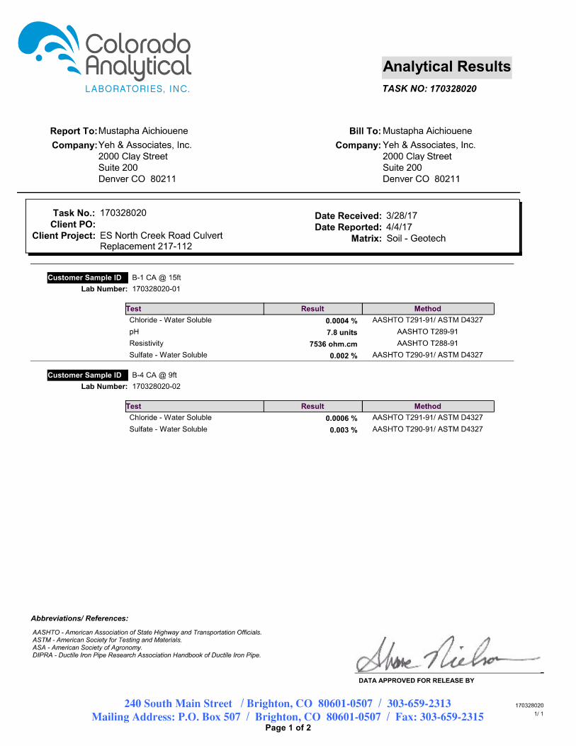
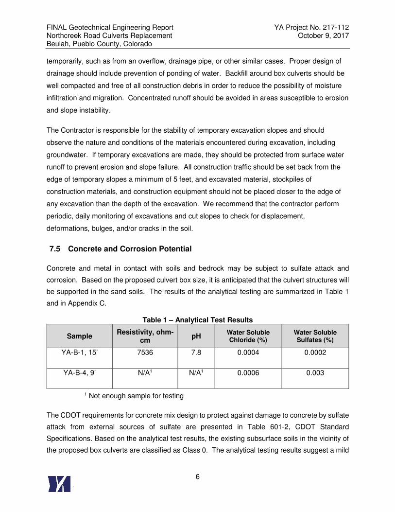
7.5 Concrete and Corrosion Potential
Concrete and metal in contact with soils and bedrock may be subject to sulfate attack and
corrosion. Based on the proposed culvert box size, it is anticipated that the culvert structures will
be supported in the sand soils. The results of the analytical testing are summarized in Table 1
and in Appendix C.
Table 1 – Analytical Test Results
Sample Resistivity, ohm-
cm pH
Water Soluble Chloride (%)
Water Soluble Sulfates (%)
YA-B-1, 15’ 7536 7.8 0.0004 0.0002
YA-B-4, 9’ N/A1 N/A1 0.0006 0.003
1 Not enough sample for testing
The CDOT requirements for concrete mix design to protect against damage to concrete by sulfate
attack from external sources of sulfate are presented in Table 601-2, CDOT Standard
Specifications. Based on the analytical test results, the existing subsurface soils in the vicinity of
the proposed box culverts are classified as Class 0. The analytical testing results suggest a mild
FINAL Geotechnical Engineering Report YA Project No. 217-112 Northcreek Road Culverts Replacement October 9, 2017 Beulah, Pueblo County, Colorado
7
to no corrosion potential towards metal based on values per Table C.1 of FHWA report FHWA0-
IF-3-017, Geotechnical Engineering Circular No. 7 – Soil Nail Walls.
8 FOUNDATION RECOMMENDATIONS
Based on our geotechnical site evaluation and understanding of the proposed box culvert
structures, it is our opinion that the box culverts and wingwalls supported on properly prepared
subgrade is a viable option, provided that the subgrade are prepared in accordance with
Sections 7 of this report. The bottom of the culvert will work as a mat foundation footing to
support the weight of the structure. The wingwalls are anticipated to be supported on strip
footings that are separated from the box structure.
8.1 Bearing and Sliding Resistances
The subsurface materials encountered in the borings are suitable for mat foundations
proportioned using a nominal bearing resistance of 6,700 psf, and a factored bearing resistance
of 3,000 psf with a resistance factor of 0.45. A modulus of subgrade reaction of 125 pci based
on a 1-foot by 1-foot plate can be used for the design. The modulus of subgrade reaction
should be modified according to the actual size of the footing. Resistance to sliding at the
bottom of foundations can be calculated based on a coefficient of friction at the interface
between the concrete and the foundation soils. We recommend the factored coefficient of
friction of 0.5 (a resistance factor of 0.80 is incorporated) for the structure placed on the properly
prepared granular subgrade.
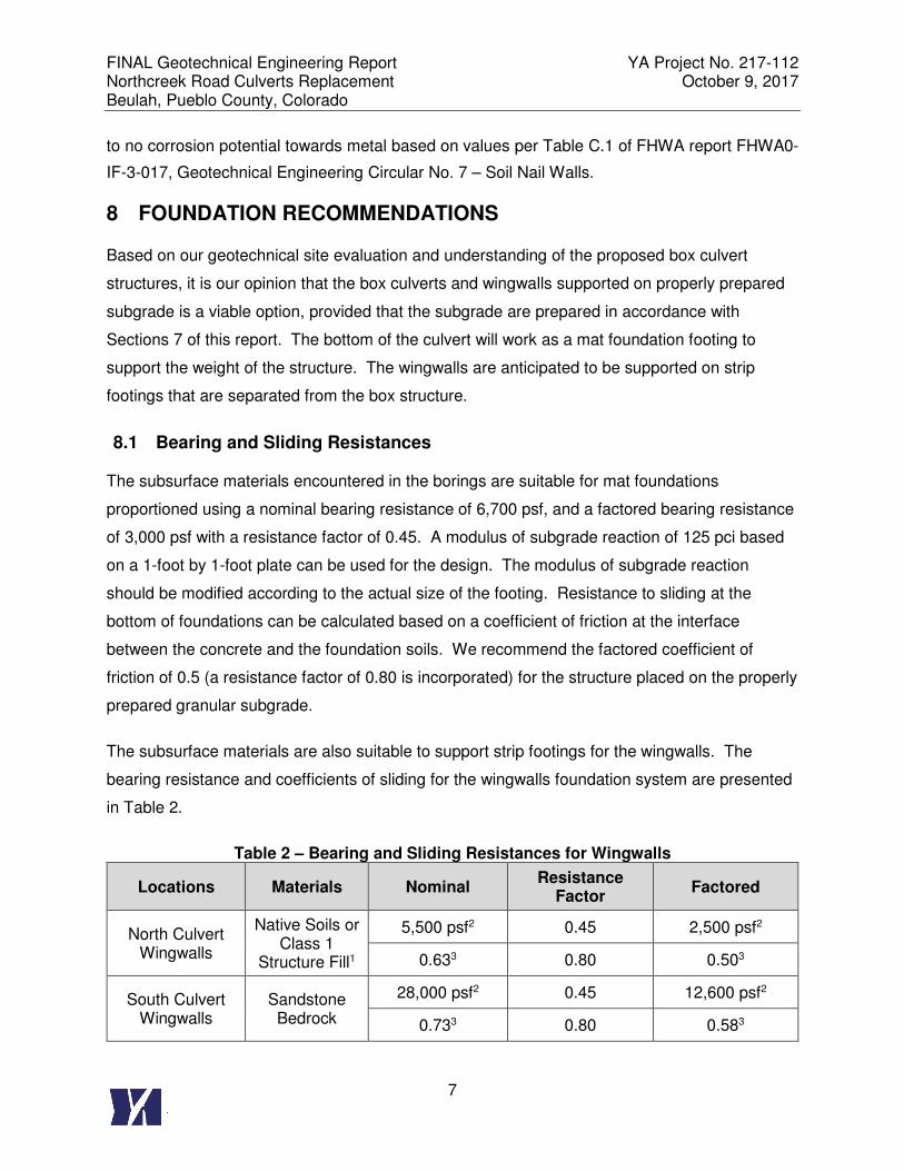
The subsurface materials are also suitable to support strip footings for the wingwalls. The
bearing resistance and coefficients of sliding for the wingwalls foundation system are presented
in Table 2.
Table 2 – Bearing and Sliding Resistances for Wingwalls
Locations Materials Nominal Resistance
Factor Factored
North Culvert Wingwalls
Native Soils or Class 1
Structure Fill1
5,500 psf2 0.45 2,500 psf2
0.633 0.80 0.503
South Culvert Wingwalls
Sandstone Bedrock
28,000 psf2 0.45 12,600 psf2
0.733 0.80 0.583

FINAL Geotechnical Engineering Report YA Project No. 217-112 Northcreek Road Culverts Replacement October 9, 2017 Beulah, Pueblo County, Colorado
8
1 Due to potential dip in bedrock elevation, the wingwall foundation is recommended to be founded in
native soils or structure fill materials. If claystone bedrock is encountered below the foundation during
construction, the claystone should be excavated and replaced with Class 1 Structure Fill Materials to at
least 2 feet below the bottom of the footings. The Class 1 Structure Fill should be compacted to at least
95% of the maximum dry density, and within +/- 2% of the optimum moisture content as determined from
modified proctor test.
2 Bearing Resistance. Wingwall footings should have a minimum foundation width of 18 inches, and
founded at a minimum of 3-feet below the final grade for frost protection.
3 Coefficient of sliding resistance
8.2 Settlement
Based on the anticipated bearing materials and the recommended factored bearing resistance,
total settlement of shallow mat and spread footings due to structural loads are estimated to be
0.5 inch, and the differential settlement across the box culvert structure is estimated to be less
than 0.5 inch. The settlement is anticipated to occur within a short period of time (less than 20
days) after the construction and placement of the embankment materials above the box
culverts.
8.3 Lateral Earth Pressures
Concrete box culvert walls and wing walls will be subject to load from earth and other surcharges.
We anticipate the walls will be backfilled with imported material meeting the requirements of
CDOT Class I backfill within the wedge areas at 1:1 (H:V) slope behind the wall from the heel of
the walls. The box culvert walls will be restrained from rotation therefore should be designed with
an “at-rest” earth pressure. We understand wingwalls could be cantilevered walls on spread
footings and attached to the box culvert, but allowing for wall rotation such that they can be
designed with an “active” earth pressure. Table 3 provides nominal values for evaluation of lateral
earth loads. Hydrostatic load due to creek water level and additional surcharge due to sloping
backfill surfaces or other surcharged loading conditions should be considered and applied where
appropriate.
FINAL Geotechnical Engineering Report YA Project No. 217-112 Northcreek Road Culverts Replacement October 9, 2017 Beulah, Pueblo County, Colorado
9
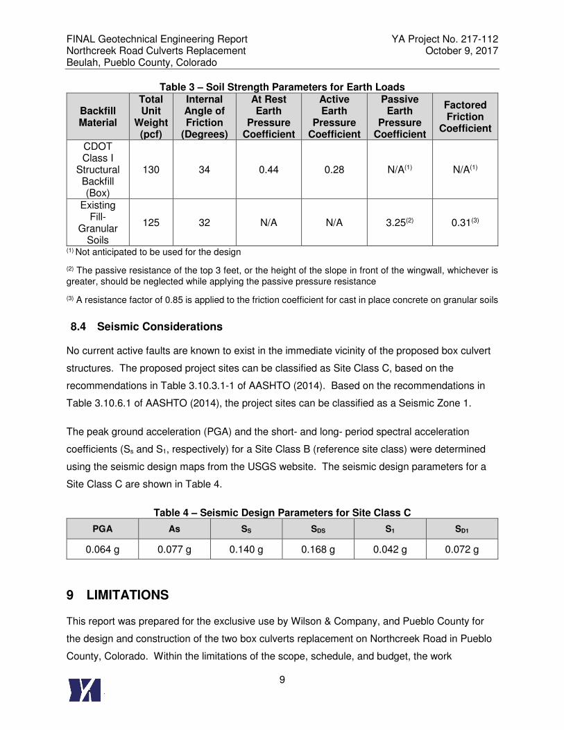
Table 3 – Soil Strength Parameters for Earth Loads
Backfill Material
Total Unit
Weight (pcf)
Internal Angle of Friction
(Degrees)
At Rest Earth
Pressure Coefficient
Active Earth
Pressure Coefficient
Passive Earth
Pressure Coefficient
Factored Friction
Coefficient
CDOT Class I
Structural Backfill (Box)
130 34 0.44 0.28 N/A(1) N/A(1)
Existing Fill-
Granular Soils
125 32 N/A N/A 3.25(2) 0.31(3)
(1) Not anticipated to be used for the design
(2) The passive resistance of the top 3 feet, or the height of the slope in front of the wingwall, whichever is
greater, should be neglected while applying the passive pressure resistance
(3) A resistance factor of 0.85 is applied to the friction coefficient for cast in place concrete on granular soils
8.4 Seismic Considerations
No current active faults are known to exist in the immediate vicinity of the proposed box culvert
structures. The proposed project sites can be classified as Site Class C, based on the
recommendations in Table 3.10.3.1-1 of AASHTO (2014). Based on the recommendations in
Table 3.10.6.1 of AASHTO (2014), the project sites can be classified as a Seismic Zone 1.
The peak ground acceleration (PGA) and the short- and long- period spectral acceleration
coefficients (Ss and S1, respectively) for a Site Class B (reference site class) were determined
using the seismic design maps from the USGS website. The seismic design parameters for a
Site Class C are shown in Table 4.
Table 4 – Seismic Design Parameters for Site Class C
PGA As SS SDS S1 SD1
0.064 g 0.077 g 0.140 g 0.168 g 0.042 g 0.072 g
9 LIMITATIONS
This report was prepared for the exclusive use by Wilson & Company, and Pueblo County for
the design and construction of the two box culverts replacement on Northcreek Road in Pueblo
County, Colorado. Within the limitations of the scope, schedule, and budget, the work
FINAL Geotechnical Engineering Report YA Project No. 217-112 Northcreek Road Culverts Replacement October 9, 2017 Beulah, Pueblo County, Colorado
10
presented in this report was performed in accordance with generally accepted principles and
practices in this area at the time this report was prepared. We make no other warranty, either
express or implied.
The classifications, conclusions, and recommendations submitted in this report are based on
the data obtained from published and unpublished maps, reports, geotechnical analyses, and
our exploratory borings. Our conclusions and recommendations are based on our
understanding of the project as described in this report and the site conditions as interpreted
from the explorations. This data may not necessarily reflect variations in the subsurface
conditions and water levels occurring at other locations.
The nature and extent of subsurface variations may not become evident until excavation is
performed. Variations in the data may also occur with the passage of time. If during
construction, fill, soil, rock, or groundwater conditions appear to be different from those
described in this report, this office should be advised immediately so we could review these
conditions and reconsider our recommendations. If there is a substantial lapse of time between
the submission of this report and the start of work at the site, or if conditions have changed
because of natural forces or construction operations at or adjacent to the site, we recommend
that this report be reviewed to determine the applicability of the conclusions and
recommendations concerning the changed conditions or time lapse. We recommend on-site
observation of foundation excavations and foundation subgrade conditions by the geotechnical
engineer of record or the engineer’s representative.
The scope of work of this investigation did not include hazardous materials sampling or
environmental sampling, investigation, or analyses. In addition, we did not evaluate the site for
potential impacts to natural resources, including wetlands, endangered species, or
environmentally critical areas.
10 REFERENCES
AASHTO, 2014. AASHTO Load-Resistance Factor Design (LRFD) Bridge Design Specifications, Seventh Edition. Washington, DC: American Association of State Highway and Transportation Officials. 2014.
Colorado Department of Transportation, 2011. CDOT Standard Specifications for Road and
Bridge Construction. Denver, Co. 2011 Edition.

FINAL Geotechnical Engineering Report YA Project No. 217-112 Northcreek Road Culverts Replacement October 9, 2017 Beulah, Pueblo County, Colorado
11
Glenn R. Scott, Richard B. Taylor, Rudy C. Epis, and Reinhard A. Wobus, 1976, Geologic Map of the Pueblo 1o x 2o Quadrangle, South-Central Colorado, Department of The Interior, United States Geological Survey
Colorado Department of Transportation, 2012. Bridge Design Manual
FINAL Geotechnical Engineering Report YA Project No. 217-112 Northcreek Road Culverts Replacement October 9, 2017 Beulah, Pueblo County, Colorado
12
Figure 1 Site Vicinity Map, Northcreek Road Culverts Replacement, Pueblo County, CO (Google Earth)
North Culvert
South Culvert
FINAL Geotechnical Engineering Report YA Project No. 217-112 Northcreek Road Culverts Replacement October 9, 2017 Beulah, Pueblo County, Colorado
13
Figure 2 Geologic Map of Area, Northcreek Road Culvert Replacement
(USGS, Scott, G.R., Taylor R.B., Epis, R.C., Wobus W.A., 1976)
North Culvert
South Culvert

Appendix A
Boring Location Plans

Appendix B
Legend, Boring Logs and Laboratory Test Results
Project Number: 217-112
Northcreek Road Culvert Replacement
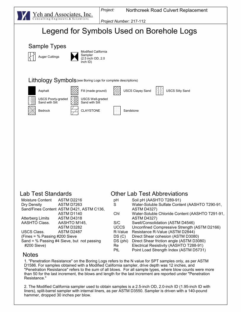
Legend for Symbols Used on Borehole Logs
Yeh and Associates, Inc.C o n s u l t i n g E n g i n e e r s & S c i e n t i s t s
Sample Types
Auger Cuttings
Modified CaliforniaSampler(2.5 inch OD, 2.0inch ID)
Lithology Symbols
Project:
(see Boring Logs for complete descriptions)
Bedrock CLAYSTONE Sandstone
Asphalt Fill (made ground) USCS Clayey Sand USCS Silty Sand
USCS Poorly-gradedSand with Silt
USCS Well-gradedSand with Silt
1. "Penetration Resistance" on the Boring Logs refers to the N value for SPT samples only, as per ASTMD1586. For samples obtained with a Modified California sampler, drive depth was 12 inches, and"Penetration Resistance" refers to the sum of all blows. For all sample types, where blow counts were morethan 50 for the last increment, the blows and length for the last increment are reported under "PenetrationResistance."
2. The Modified California sampler used to obtain samples is a 2.5-inch OD, 2.0-inch ID (1.95-inch ID withliners), split-barrel sampler with internal liners, as per ASTM D3550. Sampler is driven with a 140-poundhammer, dropped 30 inches per blow.
Lab Test Standards Other Lab Test AbbreviationspH Soil pH (AASHTO T289-91)S Water-Soluble Sulfate Content (AASHTO T290-91,
ASTM D4327)Chl Water-Soluble Chloride Content (AASHTO T291-91,
ASTM D4327)S/C Swell/Consolidation (ASTM D4546)UCCS Unconfined Compressive Strength (ASTM D2166)R-Value Resistance R-Value (ASTM D2844)DS (C) Direct Shear cohesion (ASTM D3080)DS (phi) Direct Shear friction angle (ASTM D3080)Re Electrical Resistivity (AASHTO T288-91)PtL Point Load Strength Index (ASTM D5731)
Notes
Moisture Content ASTM D2216Dry Density ASTM D7263Sand/Fines Content ASTM D421, ASTM C136,
ASTM D1140Atterberg Limits ASTM D4318AASHTO Class. AASHTO M145,
ASTM D3282USCS Class. ASTM D2487(Fines = % Passing #200 SieveSand = % Passing #4 Sieve, but not passing #200 Sieve)
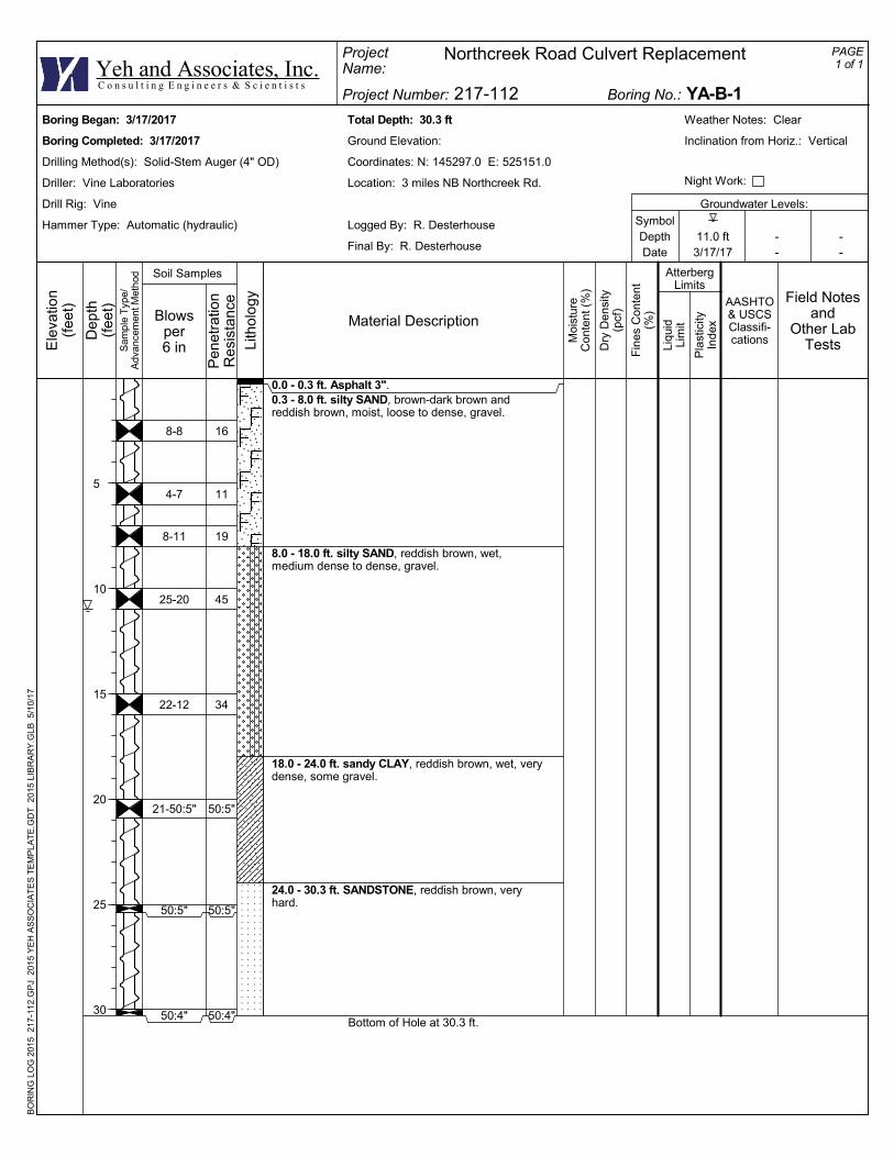
8-8
4-7
8-11
25-20
22-12
21-50:5"
50:5"
50:4"
16
11
19
45
34
50:5"
50:5"
50:4"
0.0 - 0.3 ft. Asphalt 3".0.3 - 8.0 ft. silty SAND, brown-dark brown andreddish brown, moist, loose to dense, gravel.
8.0 - 18.0 ft. silty SAND, reddish brown, wet,medium dense to dense, gravel.
18.0 - 24.0 ft. sandy CLAY, reddish brown, wet, verydense, some gravel.
24.0 - 30.3 ft. SANDSTONE, reddish brown, veryhard.
Bottom of Hole at 30.3 ft.
Total Depth: 30.3 ft
Ground Elevation:
Coordinates: N: 145297.0 E: 525151.0
Location: 3 miles NB Northcreek Rd.
Groundwater Levels:
Logged By: R. Desterhouse
Final By: R. Desterhouse
SymbolDepthDate
Weather Notes: Clear
Inclination from Horiz.: Vertical
Boring Began: 3/17/2017
Boring Completed: 3/17/2017
Drilling Method(s): Solid-Stem Auger (4" OD)
Driller: Vine Laboratories
Drill Rig: Vine
Hammer Type: Automatic (hydraulic)11.0 ft3/17/17
--
--
Night Work:
ProjectName:
PAGE1 of 1
AASHTO& USCSClassifi-cations
Fin
es C
onte
nt(%
)
Pla
stic
ityIn
dex
Project Number: 217-112
Northcreek Road Culvert Replacement
AtterbergLimits
Boring No.: YA-B-1Yeh and Associates, Inc.
Ele
vatio
n(f
eet)
Dep
th(f
eet)
5
10
15
20
25
30
Sam
ple
Typ
e/A
dvan
cem
ent M
etho
d
C o n s u l t i n g E n g i n e e r s & S c i e n t i s t s
Liqu
idLi
mit
Field Notesand
Other LabTests
BO
RIN
G L
OG
201
5 2
17-1
12.
GP
J 2
015
YE
H A
SS
OC
IAT
ES
TE
MP
LAT
E.G
DT
201
5 L
IBR
AR
Y.G
LB 5
/10
/17
Moi
stur
eC
onte
nt (
%)
Dry
Den
sity
(pcf
)Blowsper6 in
Pen
etra
tion
Res
ista
nce
Lith
olo
gy
Material Description
Soil Samples
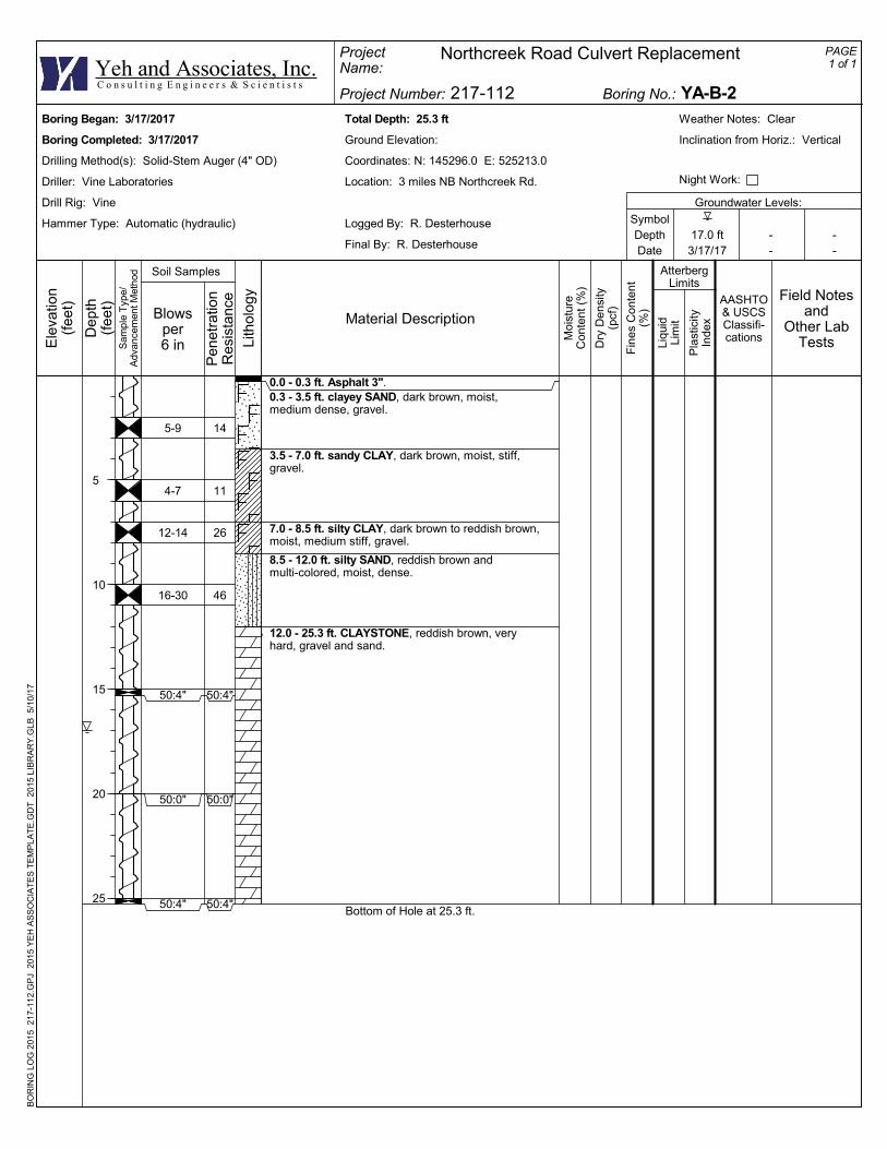
5-9
4-7
12-14
16-30
50:4"
50:0"
50:4"
14
11
26
46
50:4"
50:0"
50:4"
0.0 - 0.3 ft. Asphalt 3".0.3 - 3.5 ft. clayey SAND, dark brown, moist,medium dense, gravel.
3.5 - 7.0 ft. sandy CLAY, dark brown, moist, stiff,gravel.
7.0 - 8.5 ft. silty CLAY, dark brown to reddish brown,moist, medium stiff, gravel.
8.5 - 12.0 ft. silty SAND, reddish brown andmulti-colored, moist, dense.
12.0 - 25.3 ft. CLAYSTONE, reddish brown, veryhard, gravel and sand.
Bottom of Hole at 25.3 ft.
Total Depth: 25.3 ft
Ground Elevation:
Coordinates: N: 145296.0 E: 525213.0
Location: 3 miles NB Northcreek Rd.
Groundwater Levels:
Logged By: R. Desterhouse
Final By: R. Desterhouse
SymbolDepthDate
Weather Notes: Clear
Inclination from Horiz.: Vertical
Boring Began: 3/17/2017
Boring Completed: 3/17/2017
Drilling Method(s): Solid-Stem Auger (4" OD)
Driller: Vine Laboratories
Drill Rig: Vine
Hammer Type: Automatic (hydraulic)17.0 ft3/17/17
--
--
Night Work:
ProjectName:
PAGE1 of 1
AASHTO& USCSClassifi-cations
Fin
es C
onte
nt(%
)
Pla
stic
ityIn
dex
Project Number: 217-112
Northcreek Road Culvert Replacement
AtterbergLimits
Boring No.: YA-B-2Yeh and Associates, Inc.
Ele
vatio
n(f
eet)
Dep
th(f
eet)
5
10
15
20
25
Sam
ple
Typ
e/A
dvan
cem
ent M
etho
d
C o n s u l t i n g E n g i n e e r s & S c i e n t i s t s
Liqu
idLi
mit
Field Notesand
Other LabTests
BO
RIN
G L
OG
201
5 2
17-1
12.
GP
J 2
015
YE
H A
SS
OC
IAT
ES
TE
MP
LAT
E.G
DT
201
5 L
IBR
AR
Y.G
LB 5
/10
/17
Moi
stur
eC
onte
nt (
%)
Dry
Den
sity
(pcf
)Blowsper6 in
Pen
etra
tion
Res
ista
nce
Lith
olo
gy
Material Description
Soil Samples
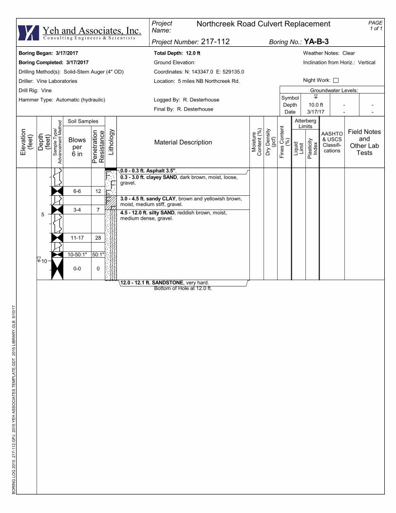
6-6
3-4
11-17
10-50:1"
0-0
12
7
28
50:1"
0
0.0 - 0.3 ft. Asphalt 3.5".0.3 - 3.0 ft. clayey SAND, dark brown, moist, loose,gravel.
3.0 - 4.5 ft. sandy CLAY, brown and yellowish brown,moist, medium stiff, gravel.
4.5 - 12.0 ft. silty SAND, reddish brown, moist,medium dense, gravel.
12.0 - 12.1 ft. SANDSTONE, very hard.Bottom of Hole at 12.0 ft.
Total Depth: 12.0 ft
Ground Elevation:
Coordinates: N: 143347.0 E: 529135.0
Location: 5 miles NB Northcreek Rd.
Groundwater Levels:
Logged By: R. Desterhouse
Final By: R. Desterhouse
SymbolDepthDate
Weather Notes: Clear
Inclination from Horiz.: Vertical
Boring Began: 3/17/2017
Boring Completed: 3/17/2017
Drilling Method(s): Solid-Stem Auger (4" OD)
Driller: Vine Laboratories
Drill Rig: Vine
Hammer Type: Automatic (hydraulic)10.0 ft3/17/17
--
--
Night Work:
ProjectName:
PAGE1 of 1
AASHTO& USCSClassifi-cations
Fin
es C
onte
nt(%
)
Pla
stic
ityIn
dex
Project Number: 217-112
Northcreek Road Culvert Replacement
AtterbergLimits
Boring No.: YA-B-3Yeh and Associates, Inc.
Ele
vatio
n(f
eet)
Dep
th(f
eet)
5
10
Sam
ple
Typ
e/A
dvan
cem
ent M
etho
d
C o n s u l t i n g E n g i n e e r s & S c i e n t i s t s
Liqu
idLi
mit
Field Notesand
Other LabTests
BO
RIN
G L
OG
201
5 2
17-1
12.
GP
J 2
015
YE
H A
SS
OC
IAT
ES
TE
MP
LAT
E.G
DT
201
5 L
IBR
AR
Y.G
LB 5
/10
/17
Moi
stur
eC
onte
nt (
%)
Dry
Den
sity
(pcf
)Blowsper6 in
Pen
etra
tion
Res
ista
nce
Lith
olo
gy
Material Description
Soil Samples

3-3
4-5
1-1
9-19
50:1"
0
6
9
2
28
50:1"
0
0.0 - 0.4 ft. Asphalt 3.5", gravel.0.4 - 6.0 ft. clayey SAND, dark brown to reddishbrown, moist, loose, gravel.
6.0 - 7.5 ft. sandy CLAY, reddish brown, moist, soft.
7.5 - 11.0 ft. silty SAND, reddish brown, moist towet, medium dense.
11.0 - 20.0 ft. SANDSTONE, reddish brown, veryhard.
Bottom of Hole at 20.0 ft.
Total Depth: 20.0 ft
Ground Elevation:
Coordinates: N: 143331.0 E: 529171.0
Location: 5 miles NB Northcreek Rd.
Groundwater Levels:
Logged By: R. Desterhouse
Final By: R. Desterhouse
SymbolDepthDate
Weather Notes: Clear
Inclination from Horiz.: Vertical
Boring Began: 3/17/2017
Boring Completed: 3/17/2017
Drilling Method(s): Solid-Stem Auger (4" OD)
Driller: Vine Laboratories
Drill Rig: Vine
Hammer Type: Automatic (hydraulic)10.0 ft3/17/17
--
--
Night Work:
ProjectName:
PAGE1 of 1
AASHTO& USCSClassifi-cations
Fin
es C
onte
nt(%
)
Pla
stic
ityIn
dex
Project Number: 217-112
Northcreek Road Culvert Replacement
AtterbergLimits
Boring No.: YA-B-4Yeh and Associates, Inc.
Ele
vatio
n(f
eet)
Dep
th(f
eet)
5
10
15
20
Sam
ple
Typ
e/A
dvan
cem
ent M
etho
d
C o n s u l t i n g E n g i n e e r s & S c i e n t i s t s
Liqu
idLi
mit
Field Notesand
Other LabTests
BO
RIN
G L
OG
201
5 2
17-1
12.
GP
J 2
015
YE
H A
SS
OC
IAT
ES
TE
MP
LAT
E.G
DT
201
5 L
IBR
AR
Y.G
LB 5
/10
/17
Moi
stur
eC
onte
nt (
%)
Dry
Den
sity
(pcf
)Blowsper6 in
Pen
etra
tion
Res
ista
nce
Lith
olo
gy
Material Description
Soil Samples
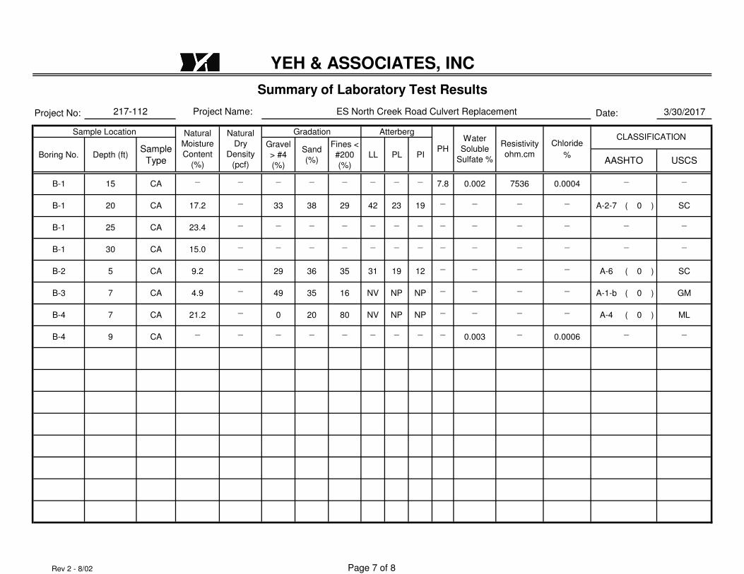
Project No: Date: 3/30/2017
Gradation Atterberg
Chloride
%
B-1 15 CA_ _ _ _ _ _ _ _
7.8 0.002 7536 0.0004_ _
B-1 20 CA 17.2_
33 38 29 42 23 19_ _ _ _
A-2-7 ( 0 ) SC
B-1 25 CA 23.4_ _ _ _ _ _ _ _ _ _ _ _ _
B-1 30 CA 15.0_ _ _ _ _ _ _ _ _ _ _ _ _
B-2 5 CA 9.2_
29 36 35 31 19 12_ _ _ _
A-6 ( 0 ) SC
B-3 7 CA 4.9_
49 35 16 NV NP NP_ _ _ _
A-1-b ( 0 ) GM
B-4 7 CA 21.2_
0 20 80 NV NP NP_ _ _ _
A-4 ( 0 ) ML
B-4 9 CA_ _ _ _ _ _ _ _ _
0.003_
0.0006_ _
PL PIAASHTO USCS
Resistivity
ohm.cm
CLASSIFICATIONWater
Soluble
Sulfate %
Sample
Type
Gravel
> #4
(%)
Sand
(%)
Fines <
#200
(%)
217-112 Project Name:
LL
YEH & ASSOCIATES, INC
Summary of Laboratory Test Results
Sample Location Natural
Moisture
Content
(%)
Natural
Dry
Density
(pcf)
PH
ES North Creek Road Culvert Replacement
Boring No. Depth (ft)
Rev 2 - 8/02 Page 7 of 8
Drawn By: M.A
Date: 03/30/17
Sieve
Size
%
Passing
Checked By: HML
-
-
-
3"
2 ½"
2"
⅜"
#4
#10
#40
1 ½"
1"
Sample
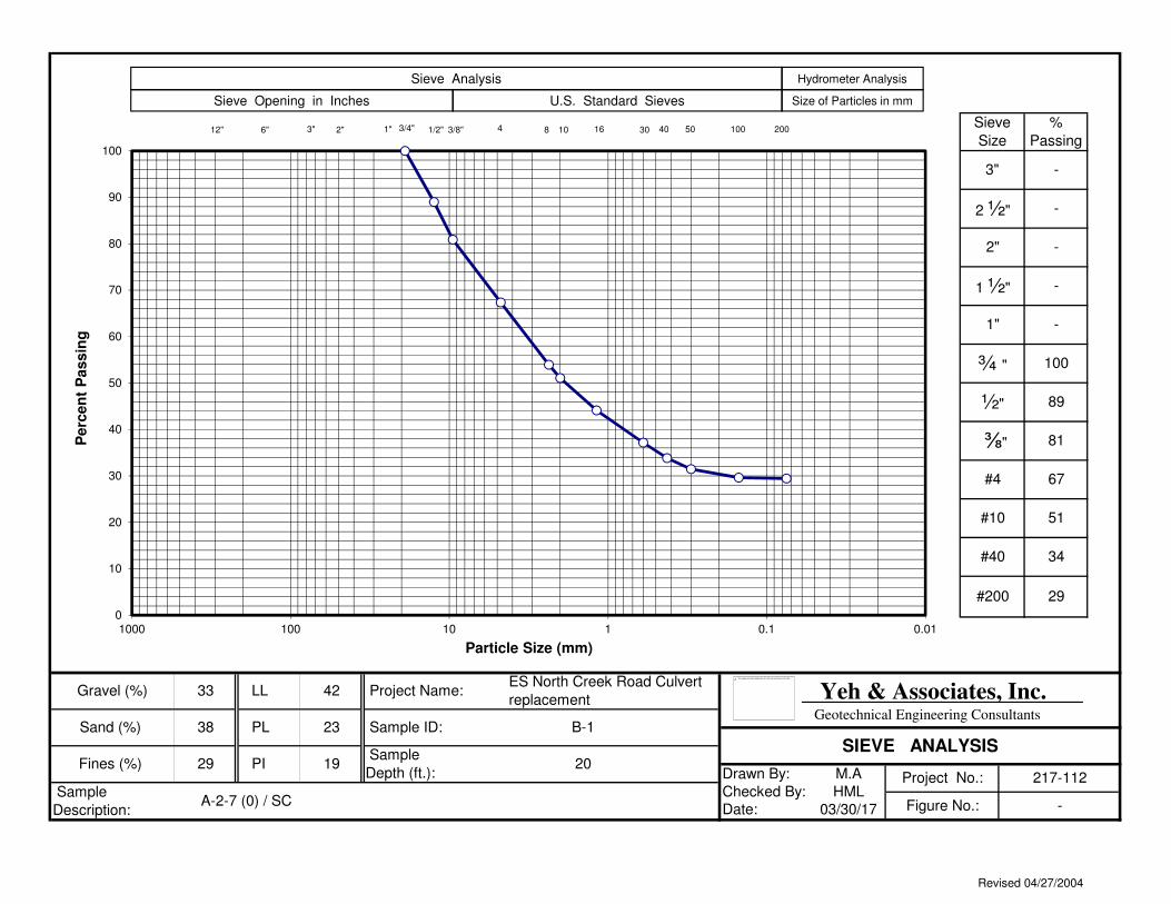
Description:A-2-7 (0) / SC
Project No.: 217-112
Figure No.: -
Fines (%) 29 PI 19
ES North Creek Road Culvert
replacement Project Name:
Sample ID: B-1
Sample
Depth (ft.):20
Gravel (%)
Sand (%)
33
38
LL
PL
¾ "
½"
42
23
-
-
51
34
100
89
81
67
#200 29
Yeh & Associates, Inc. Geotechnical Engineering Consultants
SIEVE ANALYSIS
0
10
20
30
40
50
60
70
80
90
100
0.010.11101001000
Perc
en
t P
assin
g
Particle Size (mm)
20040103/8" 41/2"3/4"3"12" 6" 1" 30 508 16
Sieve Analysis Hydrometer Analysis
Sieve Opening in Inches U.S. Standard Sieves Size of Particles in mm
100
The image part with relationship ID rId2 was not found in the file.
2"
Revised 04/27/2004
Drawn By: M.A
Date: 03/30/17
Sieve
Size
%
Passing
Checked By: HML
-
-
-
3"
2 ½"
2"
⅜"
#4
#10
#40
1 ½"
1"
Sample
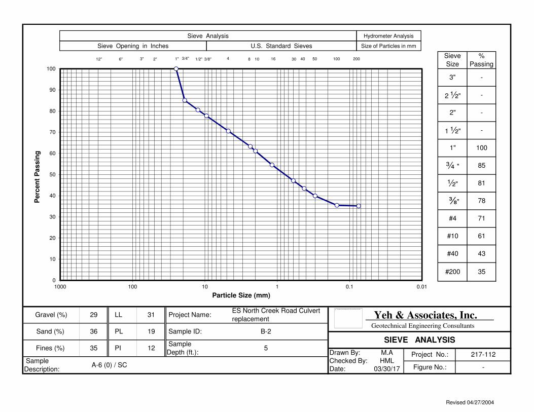
Description:A-6 (0) / SC
Project No.: 217-112
Figure No.: -
Fines (%) 35 PI 12
ES North Creek Road Culvert
replacement Project Name:
Sample ID: B-2
Sample
Depth (ft.):5
Gravel (%)
Sand (%)
29
36
LL
PL
¾ "
½"
31
19
-
100
61
43
85
81
78
71
#200 35
Yeh & Associates, Inc. Geotechnical Engineering Consultants
SIEVE ANALYSIS
0
10
20
30
40
50
60
70
80
90
100
0.010.11101001000
Perc
en
t P
assin
g
Particle Size (mm)
20040103/8" 41/2"3/4"3"12" 6" 1" 30 508 16
Sieve Analysis Hydrometer Analysis
Sieve Opening in Inches U.S. Standard Sieves Size of Particles in mm
100
The image part with relationship ID rId2 was not found in the file.
2"
Revised 04/27/2004
Drawn By: M.A
Date: 03/30/17
Sieve
Size
%
Passing
Checked By: HML
-
-
-
3"
2 ½"
2"
⅜"
#4
#10
#40
1 ½"
1"
Sample
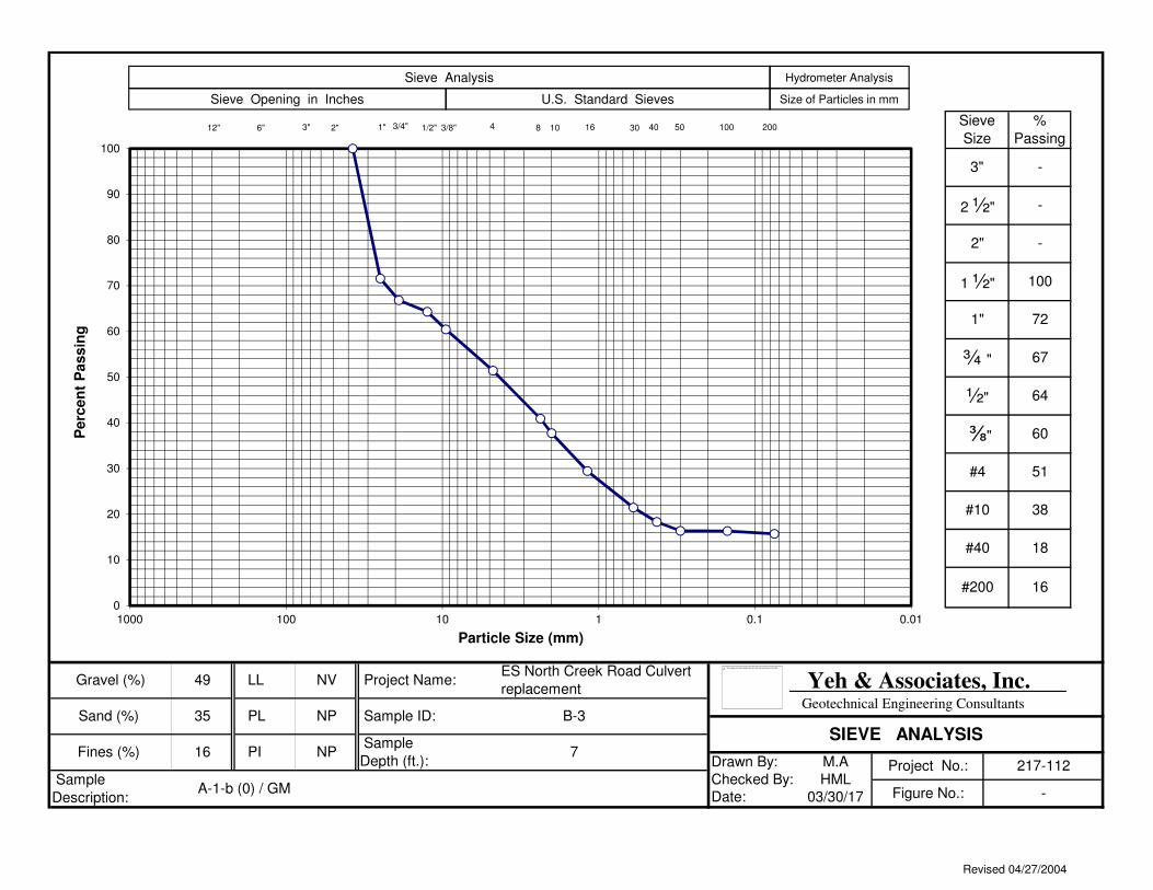
Description:A-1-b (0) / GM
Project No.: 217-112
Figure No.: -
Fines (%) 16 PI NP
ES North Creek Road Culvert
replacement Project Name:
Sample ID: B-3
Sample
Depth (ft.):7
Gravel (%)
Sand (%)
49
35
LL
PL
¾ "
½"
NV
NP
100
72
38
18
67
64
60
51
#200 16
Yeh & Associates, Inc. Geotechnical Engineering Consultants
SIEVE ANALYSIS
0
10
20
30
40
50
60
70
80
90
100
0.010.11101001000
Perc
en
t P
assin
g
Particle Size (mm)
20040103/8" 41/2"3/4"3"12" 6" 1" 30 508 16
Sieve Analysis Hydrometer Analysis
Sieve Opening in Inches U.S. Standard Sieves Size of Particles in mm
100
The image part with relationship ID rId2 was not found in the file.
2"
Revised 04/27/2004
Drawn By: M.A
Date: 03/30/17
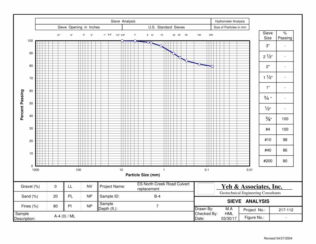
¾ "
½"
NV
NP
-
-
98
86
-
-
100
100
#200 80
Yeh & Associates, Inc. Geotechnical Engineering Consultants
SIEVE ANALYSIS
Gravel (%)
Sand (%)
0
20
LL
PL
ES North Creek Road Culvert
replacement Project Name:
Sample ID: B-4
Sample
Depth (ft.):7
Sample
Description:A-4 (0) / ML
Project No.: 217-112
Figure No.: -
Fines (%) 80 PI NP
Sieve
Size
%
Passing
Checked By: HML
-
-
-
3"
2 ½"
2"
⅜"
#4
#10
#40
1 ½"
1"
0
10
20
30
40
50
60
70
80
90
100
0.010.11101001000
Perc
en
t P
assin
g
Particle Size (mm)
20040103/8" 41/2"3/4"3"12" 6" 1" 30 508 16
Sieve Analysis Hydrometer Analysis
Sieve Opening in Inches U.S. Standard Sieves Size of Particles in mm
100
The image part with relationship ID rId2 was not found in the file.
2"
Revised 04/27/2004

Appendix C
Analytical Test Results