FINAL Duevel AREMA Retaining Wall Design for the … Wall Design for the Railroad Infrastructure:...
22
Retaining Wall Design for the Railroad Infrastructure: What Makes Its Design and Construction Unique? A Selection Approach Authors’ Names and Contact Information: Bryan Duevel Jacobs Associates 101 SW Main Street, Suite 360 Portland, OR 97204 503.384.2914 [email protected] Heather Stewart Jacobs Associates 1109 First Ave, Suite 501 Seattle WA 98101 206.588.8181 [email protected] Rick Smith Jacobs Associates 1109 First Ave, Suite 501 Seattle WA 98101 206.588.8138 [email protected] Word Count This manuscript has 4,584 words, 8 figures, and 1 table. ABSTRACT Many railroad infrastructure projects today require retaining walls to solve a variety of grade differential problems. Retaining walls for railroad infrastructure have a number of unique design and construction considerations not present in many other applications including limited right-of-way, heavy surcharges, environmental limitations, track time constraints, and limited work areas. These make the selection of appropriate retaining wall systems and their design more complex. Walls can generally be grouped into gravity and nongravity types, with the category based on how load resistance is developed. Contrary to suppliers’ statements, no single wall type solves all design issues. By knowing the controlling design and construction characteristics of each, the designer may combine the known site conditions, design requirements and railroad considerations such as surcharge loading and ROW constraints, and impacts to existing infrastructure to select the most appropriate wall system. In many cases, the most © AREMA 2014 1
-
Upload
duongxuyen -
Category
Documents
-
view
216 -
download
2
Transcript of FINAL Duevel AREMA Retaining Wall Design for the … Wall Design for the Railroad Infrastructure:...
Retaining Wall Design for the Railroad Infrastructure: What Makes Its Design and Construction Unique? A Selection Approach
Authors’ Names and Contact Information: Bryan Duevel Jacobs Associates 101 SW Main Street, Suite 360 Portland, OR 97204 503.384.2914 [email protected] Heather Stewart Jacobs Associates 1109 First Ave, Suite 501 Seattle WA 98101 206.588.8181 [email protected] Rick Smith Jacobs Associates 1109 First Ave, Suite 501 Seattle WA 98101 206.588.8138 [email protected]
Word Count This manuscript has 4,584 words, 8 figures, and 1 table.
ABSTRACT Many railroad infrastructure projects today require retaining walls to solve a variety of grade differential problems. Retaining walls for railroad infrastructure have a number of unique design and construction considerations not present in many other applications including limited right-of-way, heavy surcharges, environmental limitations, track time constraints, and limited work areas. These make the selection of appropriate retaining wall systems and their design more complex. Walls can generally be grouped into gravity and nongravity types, with the category based on how load resistance is developed. Contrary to suppliers’ statements, no single wall type solves all design issues. By knowing the controlling design and construction characteristics of each, the designer may combine the known site conditions, design requirements and railroad considerations such as surcharge loading and ROW constraints, and impacts to existing infrastructure to select the most appropriate wall system. In many cases, the most
© AREMA 2014 1

inexpensive wall system (in terms of material and construction costs alone) is not the most cost-effective system when considering the “big picture.” This paper summarizes the special design and construction constraints and considerations of retaining walls encountered with railroad infrastructure, and presents a practical approach to preliminary selection of the wall type for the site conditions and constraints.
INTRODUCTION
Many railroad infrastructure projects today involve modifying existing infrastructure to replace aging components or expand them to increase capacity or improve safety. Retaining walls are often used to solve a variety of grade differential problems associated with these improvements. Walls are required to create additional horizontal space for parallel track systems, for small areas such as signals and switch motor pads, or construction staging (such as turnout pads) at the same grade as the existing tracks. Walls are also frequently a part of projects because of the presence of existing infrastructure and restrictions of right-of-way (ROW).
Retaining walls for railroad infrastructure have a number of unique design and construction considerations not present in many other applications. This makes the selection of the appropriate retaining wall system and its design more complex. Therefore input should be obtained from many different disciplines, including environmental, civil, structural, and geotechnical, as well as railroad operations.
This paper summarizes the special design and construction constraints and considerations of retaining walls in railroad infrastructure, and a practical approach to preliminary selection of the wall type for the site conditions and constraints. The paper provides a general overview of wall systems, appropriate for siting studies and preliminary design. GENERAL CLASSIFICATION OF WALLS
Common Retaining Wall Types by How They Resist Loads
Retaining wall systems may be broken down into general categories based on how the structures resist load. For simplification, wall types have been categorized as “gravity” and “nongravity” walls. These wall types may be used in both cut and fill applications. Gravity Walls
Gravity walls resist loads primarily by the dead weight of the wall. Typical gravity wall systems used in railroad applications include cast-in-place concrete and cantilever walls, modular block walls, T-Walls (R), soil nail walls, and mechanically stabilized earth (MSE) walls. These walls typically have a footprint (base width) from 0.7 to 1.0 times the wall height and are founded at shallow depths. These walls are suitable over a wide range of foundation conditions; in areas of poor ground, foundation soils can be improved with well-established methods. When compared with nongravity walls, gravity walls are easier to construct and significantly less expensive (when considering only the
© AREMA 2014 2
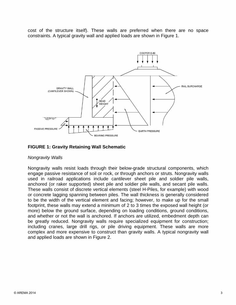
cost of the structure itself). These walls are preferred when there are no space constraints. A typical gravity wall and applied loads are shown in Figure 1.
FIGURE 1: Gravity Retaining Wall Schematic Nongravity Walls
Nongravity walls resist loads through their below-grade structural components, which engage passive resistance of soil or rock, or through anchors or struts. Nongravity walls used in railroad applications include cantilever sheet pile and soldier pile walls, anchored (or raker supported) sheet pile and soldier pile walls, and secant pile walls. These walls consist of discrete vertical elements (steel H-Piles, for example) with wood or concrete lagging spanning between piles. The wall thickness is generally considered to be the width of the vertical element and facing; however, to make up for the small footprint, these walls may extend a minimum of 2 to 3 times the exposed wall height (or more) below the ground surface, depending on loading conditions, ground conditions, and whether or not the wall is anchored. If anchors are utilized, embedment depth can be greatly reduced. Nongravity walls require specialized equipment for construction; including cranes, large drill rigs, or pile driving equipment. These walls are more complex and more expensive to construct than gravity walls. A typical nongravity wall and applied loads are shown in Figure 2.
© AREMA 2014 3

FIGURE 2: Nongravity Retaining Wall Schematic Classification of Retaining Walls by Construction Methods or Approach
Retaining wall systems may also be categorized by their method of construction. Construction methods may be more critical to their selection than cost or structural simplicity. The most common construction methods are described below and shown in Figure 3. Excavation and Backfill
This is simplest construction method. It may be used when there are no footprint constraints, and is commonly used for gravity walls. The site is excavated to the base of the wall; excavation sidewalls are sloped to maintain a safe excavation. Typical temporary excavation slopes for railroad construction range from 1.5 horizontal to 1 vertical (1.5H:1V) to 1H:1V, depending on the soil and rock, and loading conditions. When developing preliminary layouts, 1.5H:1V excavation slopes should be assumed. Typically, the base of the excavation extends a few feet beyond the width of the wall to allow for the placement of drainage materials. After completing the excavation, the retaining wall is constructed on its own followed by backfilling to final grades. Certain types of walls may be backfilled simultaneously as they are constructed (such as T-Walls, and MSE walls).
© AREMA 2014 4
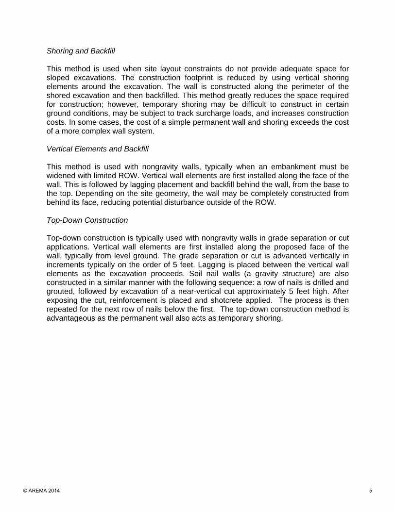
Shoring and Backfill
This method is used when site layout constraints do not provide adequate space for sloped excavations. The construction footprint is reduced by using vertical shoring elements around the excavation. The wall is constructed along the perimeter of the shored excavation and then backfilled. This method greatly reduces the space required for construction; however, temporary shoring may be difficult to construct in certain ground conditions, may be subject to track surcharge loads, and increases construction costs. In some cases, the cost of a simple permanent wall and shoring exceeds the cost of a more complex wall system. Vertical Elements and Backfill
This method is used with nongravity walls, typically when an embankment must be widened with limited ROW. Vertical wall elements are first installed along the face of the wall. This is followed by lagging placement and backfill behind the wall, from the base to the top. Depending on the site geometry, the wall may be completely constructed from behind its face, reducing potential disturbance outside of the ROW. Top-Down Construction
Top-down construction is typically used with nongravity walls in grade separation or cut applications. Vertical wall elements are first installed along the proposed face of the wall, typically from level ground. The grade separation or cut is advanced vertically in increments typically on the order of 5 feet. Lagging is placed between the vertical wall elements as the excavation proceeds. Soil nail walls (a gravity structure) are also constructed in a similar manner with the following sequence: a row of nails is drilled and grouted, followed by excavation of a near-vertical cut approximately 5 feet high. After exposing the cut, reinforcement is placed and shotcrete applied. The process is then repeated for the next row of nails below the first. The top-down construction method is advantageous as the permanent wall also acts as temporary shoring.
© AREMA 2014 5

FIGURE 3: Retaining Wall Construction Methods
© AREMA 2014 6
COMMON RAILROAD DESIGN ISSUES
Retaining walls for railroad structures have a number of unique aspects that make their design challenging. Common design issues are described in the following sections. Surcharge
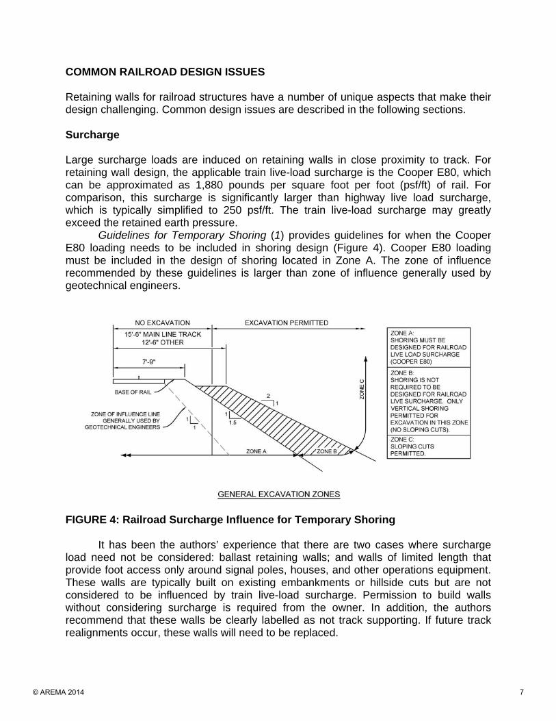
Large surcharge loads are induced on retaining walls in close proximity to track. For retaining wall design, the applicable train live-load surcharge is the Cooper E80, which can be approximated as 1,880 pounds per square foot per foot (psf/ft) of rail. For comparison, this surcharge is significantly larger than highway live load surcharge, which is typically simplified to 250 psf/ft. The train live-load surcharge may greatly exceed the retained earth pressure.
Guidelines for Temporary Shoring (1) provides guidelines for when the Cooper E80 loading needs to be included in shoring design (Figure 4). Cooper E80 loading must be included in the design of shoring located in Zone A. The zone of influence recommended by these guidelines is larger than zone of influence generally used by geotechnical engineers.
FIGURE 4: Railroad Surcharge Influence for Temporary Shoring
It has been the authors’ experience that there are two cases where surcharge load need not be considered: ballast retaining walls; and walls of limited length that provide foot access only around signal poles, houses, and other operations equipment. These walls are typically built on existing embankments or hillside cuts but are not considered to be influenced by train live-load surcharge. Permission to build walls without considering surcharge is required from the owner. In addition, the authors recommend that these walls be clearly labelled as not track supporting. If future track realignments occur, these walls will need to be replaced.
© AREMA 2014 7
Limited ROW
Most railroad projects today involve making modifications to existing infrastructure within well-established corridors. Oftentimes, ROW boundaries were established at the base of embankments long ago (well before thoughts of future expansion). Since their original construction, new infrastructure has developed adjacent to the corridor or undeveloped land is being held by uncooperative landowners. These limit the options for modifying existing track or adding new track, requiring that existing space be maximized. Typically, this results in higher surcharge loads because walls must be constructed close to tracks. Wetlands
Another common issue with railroad expansion is the presence of wetlands around existing infrastructure. At the time of original construction (often around the beginning of the 20th century), wetlands and environmental issues were not considered. Wetlands were simply filled with material to create railroad embankments.
Railroads are now frequently faced with the challenge of having to expand track up against wetland boundaries. Constructing on wetlands is technically challenging because of very weak soil conditions. Permitting wetland “takes” may cause substantial project delays. To accommodate new infrastructure, walls may be constructed to minimize or eliminate impacts to adjacent wetlands. Although constructing walls is a more expensive option than expanding embankments, delays associated with environmental permitting may ultimately make walls an economic option.
Utilities
Railroad corridors were the earliest linear connections spanning great distances and provided the easiest crossing over difficult terrain. As such, railroad corridors are also often utility corridors. The presence of critical utilities presents another logistical and geometric constraint to wall designers.
Existing Rail Infrastructure
Many railroad bridges, retaining walls, and embankment fills were constructed over 100 years ago. These structures are near the end or beyond their design life, and were not designed using current standards; however, they must meet current design standards if they are modified. A typical example is existing embankment slopes, which were built at their angle of repose. If additional load is placed on or near these slopes, they may not meet the local standard of practice with respect to stability. Geotechnical Data
Standard railroad practice typically limits subsurface data on railroad projects to one boring per half-mile, with additional borings at major structures. Geotechnical engineers must extrapolate data between boreholes to develop design parameters. In many parts
© AREMA 2014 8
of the country, subsurface conditions may be complex and vary widely over short distances. Given the uncertainty and risk with extrapolation between boreholes, design assumptions about subsurface parameters tend to be conservative.
By comparison, typical minimum spacing for state and federal highway embankments and cuts is one boring per 200 to 400 feet, and 100 feet for retaining walls (2). While this increases the project design costs, savings are generally realized many times over because of less conservative designs. More geotechnical information also reduces the likelihood of complications and claims during construction. Retaining Walls on Slopes
Designers often must consider placing retaining walls on slopes. While this approach would seem to maximize existing ROW and minimize wall heights, it is very difficult to achieve in practice because of geotechnical constraints. Bearing capacity and global stability are significantly reduced for walls founded on slopes compared with those founded on level ground. Also, this approach is often compounded by embankments that have been constructed using materials of variable quality and strength, resulting in relatively poor conditions for supporting additional loads.
Because of these factors, walls constructed on slopes generally require a wider base and deeper embedment than those constructed on level ground. These geometric factors make wall construction more difficult and expensive because larger cuts (or shoring), potentially closer to existing track, are required. Ground Anchors
Certain wall types require or may be greatly simplified by utilizing ground anchors. Ground anchors used with nongravity wall systems have the effect of reducing wall embedment depth and wall section properties. Railroad guidelines do not allow ground anchors to extend below track structure; however, in cases where great cost savings may be achieved, or there are no feasible alternatives, exemptions may sometimes be obtained from the owner. COMMON RAILROAD CONSTRUCTION ISSUES
Retaining walls for railroad structures have a number of unique construction aspects. Common construction issues related to railroad retaining walls are described in the following sections. Limited Track Time and Live-Track Construction
Different construction techniques and wall systems will impact existing lines in different ways. Construction activities may need to stop while trains pass, reducing efficiency and production rates. Lower production rates ultimately increase construction costs and schedules. Conversely, train traffic may be forced to reduce speeds while passing through construction zones, which comes at a cost to the owner in terms of reduced capacity and traffic management. The retaining wall that can be constructed with the
© AREMA 2014 9
least disruption to train traffic (in terms of slowage or stoppage) may not have the lowest overall construction cost. The costs of reduced capacity should be considered in designing structures and identifying allowable construction methods.
The availability of track time is a significant consideration in the selection of the wall system. For example, if track time is limited to a few hours a day in several small windows, then walls that can be built away from the tracks, while trains continue to pass, are favorable. Limited track time also affects how a contractor plans, schedules, and prices the work. Limited Work Areas and Staging
A large percentage of railroad projects today focus on relieving congestion and expanding capacity. This is generally achieved by adding new track parallel to existing. Inherently, this requires working close to existing, heavily trafficked corridors. The work zone is often tight, and temporary access pads, equipment size, and swing radii should be considered in design.
Railroad projects are linear, frequently narrow, and often traverse through inaccessible areas. Access points may not be near the new structure, requiring equipment to traverse long distances parallel to the track. This is also problematic for staging equipment and materials, all of which must be hauled into the work zone without impacting the public or fouling track. Difficult Ground Conditions
When driving piles for retaining walls, variable embankment soils may result in difficult installation. Embankments were often constructed using whatever material was readily available. Boulders and other obstructions, such as old trestles or other abandoned infrastructure, may be encountered.
In addition to the permitting challenges of completing work within a wetland, constructing on wetlands can be challenging because of very weak soil conditions. A geotextile fabric or geogrid with angular rock fill or granular material placed on top of it may be required to develop adequate construction access. In some cases, all work may need to be completed from the existing track embankment. Temporary Cuts and Shoring near Tracks
Many wall types require the creation of temporary cuts or shoring to provide enough space to construct the new wall. If cuts or shoring fall within the surcharge zone of influence (Figure 4), the design of these elements must be adjusted to account for the additional loads. This has the effect of flattening slopes or increasing the size and strength of temporary shoring. This ultimately increases the cost of construction.
© AREMA 2014 10
RETAINING WALL SELECTION
Selection of the optimal retaining wall system should consider technical feasibility, logistical constraints, environmental factors, cost and schedule, and means and methods. The wall selection process should consider the following series of questions: Site Constraints:
• Site Width: How much width is available for the new retaining wall? A rule of thumb is if the horizontal distance between the edge of the existing track structure and the proposed wall is greater than 2.5 times the required wall height, a gravity wall and temporary cut are feasible.
• ROW Acquisition: If there is limited space available, can additional ROW be acquired? If the ROW is expanded, wall construction may be easier and less expensive.
• Permitting: Are wetlands impacted? Are other jurisdictional agencies involved in the project? There are costs involved with the permitting process, as well as the cost of time for the permitting process. For example, if wetlands will be impacted, the project may be delayed multiple years in order to obtain the necessary permits.
• Temporary/Permanent Easements: Are easements required for construction access or for subsurface wall elements (such as tiebacks or soil nails)?
Technical Feasibility:
• Geotechnical Conditions: Do the site soils and project geometry support the new loads imposed by the wall? Is anticipated settlement compatible with the selected wall system? Different types of walls are more sensitive to settlement than others.
• Wall Stability: Does the wall adequately resist earth pressures and surcharge loads? Does the wall have an acceptable global stability factor of safety?
• Suitable System: Is the wall system consistent with railroad standards of practice?
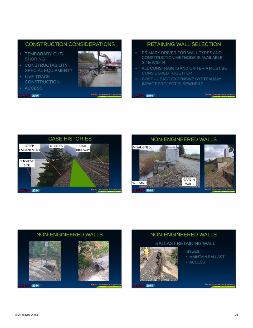
Construction Considerations:
• Temporary Shoring Requirements: Is there enough space for a temporary construction cut? Is temporary shoring required?
• Constructability: Can the wall be constructed using small equipment? Are large cranes or drill rigs required? Is there enough space for equipment?
• Live Track Construction: Can the wall be constructed efficiently under live track conditions? Will train traffic be impacted?
• Construction Access: How will construction equipment access the site? Where are equipment and materials staged?
© AREMA 2014 11
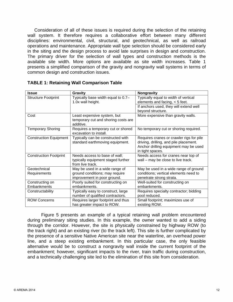
Consideration of all of these issues is required during the selection of the retaining wall system. It therefore requires a collaborative effort between many different disciplines: environmental, civil, structural, and geotechnical, as well as railroad operations and maintenance. Appropriate wall type selection should be considered early in the siting and the design process to avoid late surprises in design and construction. The primary driver for the selection of wall types and construction methods is the available site width. More options are available as site width increases. Table 1 presents a simplified comparison of the gravity and nongravity wall systems in terms of common design and construction issues. TABLE 1: Retaining Wall Comparison Table Issue Gravity Nongravity Structure Footprint Typically base width equal to 0.7–
1.0x wall height. Typically equal to width of vertical elements and facing, < 5 feet. If anchors used, they will extend well beyond structure.
Cost Least expensive system, but temporary cut and shoring costs are additive.
More expensive than gravity walls.
Temporary Shoring Requires a temporary cut or shored excavation to install.
No temporary cut or shoring required.
Construction Equipment Typically can be constructed with standard earthmoving equipment.
Requires cranes or crawler rigs for pile driving, drilling, and pile placement. Anchor drilling equipment may be used in tight spaces.
Construction Footprint Needs access to base of wall; typically equipment staged further from live track.
Needs access for cranes near top of wall – may be close to live track.
Geotechnical Requirements
May be used in a wide range of ground conditions; may require improvement in poor ground.
May be used in a wide range of ground conditions; vertical elements need to penetrate strong strata.
Constructing on Embankments
Poorly suited for constructing on embankments.
Well-suited for constructing on embankments.
Constructability Typically easy to construct, large number of qualified contractors.
Requires specialty contractor; bidding pool reduced.
ROW Concerns Requires larger footprint and thus has greater impact to ROW.
Small footprint; maximizes use of existing ROW.
Figure 5 presents an example of a typical retaining wall problem encountered
during preliminary siting studies. In this example, the owner wanted to add a siding through the corridor. However, the site is physically constrained by highway ROW (to the track right) and an existing river (to the track left). This site is further complicated by the presence of a sensitive Native American site near the waterline, an overhead power line, and a steep existing embankment. In this particular case, the only feasible alternative would be to construct a nongravity wall inside the current footprint of the embankment; however, significant impacts to the river, train traffic during construction, and a technically challenging site led to the elimination of this site from consideration.
© AREMA 2014 12

FIGURE 5: Example of Retaining Wall Problem CASE STUDIES
The following discussion presents a number of case studies illustrating examples of issues described above and solutions that were developed. Nonengineered Retaining Walls There are many retaining walls built by in-house maintenance personnel along railroad corridors. These walls are often “designed” in the field to resolve nuisance problems such as retaining ballast, or support minor structures such as signal poles. While these walls solve the immediate problem at hand, and often are creative and maximize the use of readily available materials, they typically do not meet current engineering standards for stability. Common examples of these types of walls are block walls built on steep embankments or wetlands, and soldier pile and lagging walls constructed using driven rail and railroad ties as the piles and lagging, respectively.
When owners are working with engineering consultants to design new retaining walls, they often refer to existing walls as examples of what they would like. In many cases these walls are marginally stable under static loading conditions, and there is no guarantee that the walls will remain stable under seismic loading or flood conditions. Proposed walls built in a similar fashion often do not meet industry standard practice, and in some cases, the proposed walls are in conflict with the owner’s own guidelines.
The block wall shown in Figure 6 is an example of a wall that is experiencing a global stability and/or bearing capacity failure. The result is that the base of the wall is
SENSITIVE SITE
PROPOSED SIDING
STEEP EMBANKMENT
STATE HIGHWAY
UTILITY
© AREMA 2014 13

rotating away from the embankment, as evidenced by sloping ground above the wall and gaps between blocks.
FIGURE 6: Example of Marginally Stable Nonengineered Block Wall Built Partway up an Embankment and on Wetland Deposits
This wall could have been improved by replacing foundation soils with geogrid-reinforced ballast, increasing the wall embedment depth, or increasing the wall base width.
The used rail and lagging walls shown in Figure 7 are examples of nonengineered walls built using readily available materials. These walls are built partway up existing embankments and typically utilize rail driven vertically into the ground as the soldier piles and old wooden railroad ties or bridge stringers as the lagging. The wall shown on the left appears to have been stable for some time and is assumed to be adequate for static loading conditions. However, this wall would not meet standard stability criteria, and it likely will not withstand earthquake forces. The wall shown on the right has already failed, evidenced by the wall’s negative batter of approximately 15 degrees.
© AREMA 2014 14

FIGURE 7: Example of Nonengineered Walls Constructed Using Driven Rail (left) and Miscellaneous Metal (right) for the Vertical Elements and Railroad Ties for Lagging
More robust soldier pile and lagging walls are possible engineered solutions for both of these examples. Steel HP and W piles have stiffer sections than used rail and can therefore resist higher loads. To eliminate rotational failures like the one seen in the Figure 7, piles need to be installed to a sufficient embedment depth. Ballast-supporting Soldier Pile Wall In this example, the mainline track is located on a narrow corridor along a steeply dipping rock slope (Figure 8). Because of the steep existing topography, the railroad was having difficulty maintaining alignment because the ballast along the downslope edge of the tie was sliding away. To contain the ballast, a soldier pile and tieback wall was selected for the project.
The proposed wall lies within Zone A (Figure 4); however, the new wall is required only to catch ballast and not to support the existing track section. The new wall was also shown to have no influence on the existing, stable embankment. Therefore, it was concluded that the wall did not need to be designed to support the Cooper E80 track surcharge. As an extra precaution, plaques will be placed on the wall stating this and that the existing track cannot be moved closer to the wall.
Because this wall is located along a steeply dipping slope, significant pile embedment lengths are required to develop sufficient passive resistance to support a cantilevered wall structure. From a constructability standpoint, installing the soldier piles deeply into bedrock is time consuming. To reduce embedment depth of the soldier piles, a tie-back anchor is included. The tie-back is located approximately 4 feet below the top of the wall so as to not interfere with railroad operations, utilities, and maintenance crews.
© AREMA 2014 15
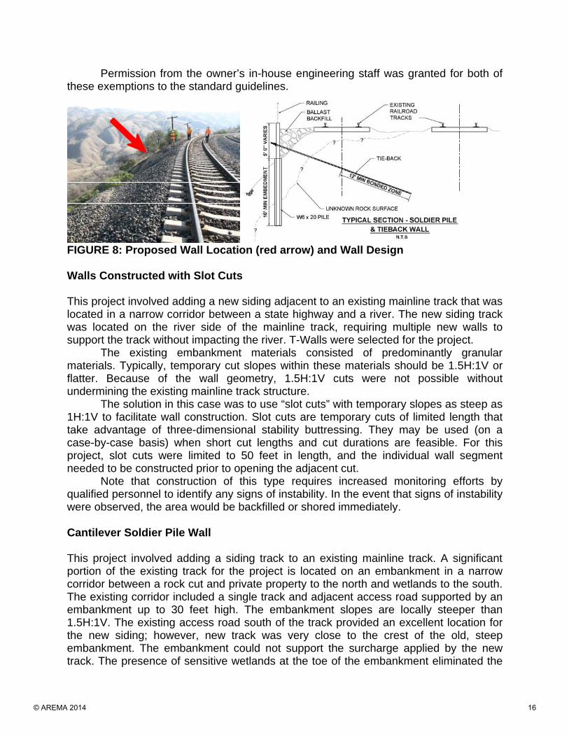
Permission from the owner’s in-house engineering staff was granted for both of these exemptions to the standard guidelines.
FIGURE 8: Proposed Wall Location (red arrow) and Wall Design Walls Constructed with Slot Cuts This project involved adding a new siding adjacent to an existing mainline track that was located in a narrow corridor between a state highway and a river. The new siding track was located on the river side of the mainline track, requiring multiple new walls to support the track without impacting the river. T-Walls were selected for the project.
The existing embankment materials consisted of predominantly granular materials. Typically, temporary cut slopes within these materials should be 1.5H:1V or flatter. Because of the wall geometry, 1.5H:1V cuts were not possible without undermining the existing mainline track structure.
The solution in this case was to use “slot cuts” with temporary slopes as steep as 1H:1V to facilitate wall construction. Slot cuts are temporary cuts of limited length that take advantage of three-dimensional stability buttressing. They may be used (on a case-by-case basis) when short cut lengths and cut durations are feasible. For this project, slot cuts were limited to 50 feet in length, and the individual wall segment needed to be constructed prior to opening the adjacent cut.
Note that construction of this type requires increased monitoring efforts by qualified personnel to identify any signs of instability. In the event that signs of instability were observed, the area would be backfilled or shored immediately. Cantilever Soldier Pile Wall This project involved adding a siding track to an existing mainline track. A significant portion of the existing track for the project is located on an embankment in a narrow corridor between a rock cut and private property to the north and wetlands to the south. The existing corridor included a single track and adjacent access road supported by an embankment up to 30 feet high. The embankment slopes are locally steeper than 1.5H:1V. The existing access road south of the track provided an excellent location for the new siding; however, new track was very close to the crest of the old, steep embankment. The embankment could not support the surcharge applied by the new track. The presence of sensitive wetlands at the toe of the embankment eliminated the
© AREMA 2014 16

possibility of expanding the embankment to support the new track. New gravity walls could not be constructed without undermining the existing mainline track. The solution was to construct a new cantilever soldier pile wall through the embankment shoulder to support the new track. The new wall eliminated impacts to the wetland as well as the need for temporary shoring. CONCLUSIONS Retaining walls for railroad infrastructure have a number of unique design issues and construction considerations. No one type of wall works for every situation. As this paper suggests, understanding the needs of the railroad operations and then combining or overlaying that with the physical and environmental site constraints allows for the most effective solution. The authors recommend that a designer be very knowledgeable of railroad operations and have a background in both geotechnical and structural design considerations to develop the best solution after the physical and environmental constraints are understood. The key to an effective design solution is a thorough understanding of soil structure interaction and knowledge of construction capabilities.
REFERENCES
1. Burlington Northern & Santa Fe Railway / Union Pacific Railroad (UPRR/BNSF. 2004. Guidelines for Temporary Shoring.
2. American Association of State Highway and Transportation Officials (AASHTO).
1988. Manual on Subsurface Investigations, 1st Edition.
Table Titles and Figure Captions TABLE 1: Retaining Wall Comparison Table FIGURE 1: Gravity Retaining Wall Schematic FIGURE 2: Non-Gravity Retaining Wall Schematic FIGURE 3: Retaining Wall Construction Methods FIGURE 4: Railroad Surcharge Influence for Temporary Shoring FIGURE 5: Example of Retaining Wall Problem FIGURE 6: Example of Marginally Stable Nonengineered Block Wall Built Partway up
an Embankment and on Wetland Deposits FIGURE 7: Example of Nonengineered Walls Constructed Using Driven Rail (left) and
Miscellaneous Metal (right) for the Vertical Elements and Railroad Ties for Lagging
FIGURE 8: Proposed Wall Location (red arrow) and Wall Design
© AREMA 2014 17
RE
TAIN
ING
WA
LL D
ES
IGN
FO
R
RA
ILR
OA
DIN
FRA
STR
UC
TUR
ER
AIL
RO
AD
INFR
AS
TRU
CTU
RE
WH
ATM
AK
ES
ITS
DE
SIG
NA
ND
CO
NS
TRU
CTI
ON
WH
AT M
AK
ES
ITS
DE
SIG
N A
ND
CO
NS
TRU
CTI
ON
U
NIQ
UE
? A
SE
LEC
TIO
N A
PP
RO
AC
H
BR
YAN
DU
EV
EL,
P.E
., G
.E.
HE
ATH
ER
STE
WA
RT,
P.E
.R
ICK
SM
ITH
PE
RIC
K S
MIT
H, P
.E.
© AREMA 2014 18

INTRODUCTION• WALLS FOR RAILROADS ARE
UNIQUE• HIGHLIGHT COMMON ISSUES
IMPORTANT TO CONSIDER EARLY• IMPORTANT TO CONSIDER EARLY• PROVIDE GUIDELINES FOR
SELECTION
WALL CLASSIFICATIONS
GRAVITY WALLS NON-GRAVITY WALLS
GRAVITY WALLS
TYPICAL GRAVITY WALLS:• CONCRETE MASS• MODULAR BLOCK WALLS• T-WALLS• CRIB WALLS• MSE WALLS
NON-GRAVITY WALLS
TYPICAL NON-GRAVITY WALLS:
• SHEET PILE • SOLDIER PILE • SECANT PILE
MAY UTILIZE STRUTS OR ANCHORS
COMMON RAIL DESIGN ISSUES
• SURCHARGE• LIMITED ROW / WETLANDS• UTILITIES
EXISTING INFRASTRUCTURE• EXISTING INFRASTRUCTURE• LIMITED GEOTECHNICAL
DATA
• REQUIRED IF SUPPORTING TRACK
• OWNERS PROVIDE
SURCHARGE – COOPER E-80 LOADING
GUIDELINES• OFTEN EXCEEDS
EARTH PRESSURE
BNSF/UPRR SHORING REQUIREMENTS (2003)
© AREMA 2014 19
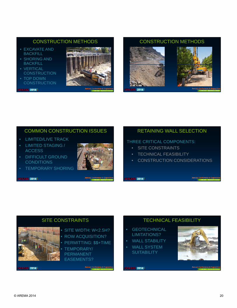
CONSTRUCTION METHODS• EXCAVATE AND
BACKFILL• SHORING AND
BACKFILLBACKFILL• VERTICAL
CONSTRUCTION• TOP DOWN
CONSTRUCTION
CONSTRUCTION METHODS
COMMON CONSTRUCTION ISSUES
• LIMITED/LIVE TRACK • LIMITED STAGING /
ACCESS• DIFFICULT GROUND
CONDITIONS• TEMPORARY SHORING
RETAINING WALL SELECTION
THREE CRITICAL COMPONENTS:• SITE CONSTRAINTS• TECHNICAL FEASIBILITY• TECHNICAL FEASIBILITY• CONSTRUCTION CONSIDERATIONS
SITE CONSTRAINTS
• SITE WIDTH: W<2.5H?• ROW ACQUISITION?• PERMITTING: $$+TIMEPERMITTING: $$+TIME• TEMPORARY/
PERMANENT EASEMENTS?
TECHNICAL FEASIBILITY
• GEOTECHNICAL LIMITATIONS?
• WALL STABILITY• WALL SYSTEM
SUITABILITY
© AREMA 2014 20
CONSTRUCTION CONSIDERATIONS
• TEMPORARY CUT/ SHORING
• CONSTRUCTABILITY: SPECIAL EQUIPMENT?
• LIVE TRACK CONSTRUCTION
• ACCESS
RETAINING WALL SELECTION• PRIMARY DRIVER FOR WALL TYPES AND
CONSTRUCTION METHODS IS AVAILABLE SITE WIDTH
• ALL CONSTRAINTS AND CRITERIA MUST BE• ALL CONSTRAINTS AND CRITERIA MUST BE CONSIDERED TOGETHER
• COST – LEAST EXPENSIVE SYSTEM MAY IMPACT PROJECT ELSEWHERE
CASE HISTORIES
SENSITIVE
STEEP EMBANKMENT
UTILITIES STATE HIGHWAY
SITE
NON-ENGINEERED WALLSMISALIGNED
BulletsWETLAND
GAPS IN WALL
NON-ENGINEERED WALLS NON-ENGINEERED WALLS
BALLAST RETAINING WALL
ISSUES:• MAINTAIN BALLAST• ACCESS
© AREMA 2014 21

BALLAST RETAINING WALL
5 FT
CANTILEVER SOLDIER PILE WALL
EXISTING TRACK
STEEP EMBANKMENT
WETLANDS
BulletsNEWTRACK
WETLANDS
CANTILEVER SOLDIER PILE WALL CANTILEVER SOLDIER PILE WALL
Bullets
CONCLUSIONS
• NO ONE WALL TYPE FOR ALL SITUATIONS• WALL SELECTION A MULTI-DISCIPLINE
EFFORTIDENTIFY ISSUES EARLY IN DESIGN• IDENTIFY ISSUES EARLY IN DESIGN
• THE LEAST EXPENSIVE STRUCTURE MAY NOT HAVE THE LEAST PROJECT IMPACT
QUESTIONS?
Bullets
© AREMA 2014 22