Final catalog 7-09 · 3 INDEX Selection Guide Page 4 Ball Slide Assemblies 7 Anti-Creep Ball Slide...
98
www.ppp-ss.com THAILAND
Transcript of Final catalog 7-09 · 3 INDEX Selection Guide Page 4 Ball Slide Assemblies 7 Anti-Creep Ball Slide...

www.ppp-ss.com THAILAND

Our Mission
Del-Tron Precision was founded in order to serve the needs of automated equipment manufacturers for innovative, highquality and reasonably priced anti-friction linear bearings.
Our Company
The originator of the sub miniature ball bearing slide assembly; Del-Tron Precision Inc. began operations in 1974supplying original equipment manufacturers with the world's first commercially available sub miniature ball slide, modelD-1.
Since then, thousands of Del-Tron® slides have been incorporated into automated equipment throughout the world.Manufacturers of medical analyzing and testing machines, semiconductor and electronic chip processing equipment,printers, plotters, peripherals, assembly systems, lasers and many more have found that Del-Tron® slides provide a costeffective anti-friction interface between moving parts in today's increasingly automated equipment.
Del-Tron's modern corporate campus, home to world headquarters, and its principal manufacturing facility, located in thefoothills of the Berkshires in Western Connecticut, boasts highly automated computer controlled manufacturing andassembly operations.
Highly skilled workers monitor each manufacturing step, ensuring that consistent and repeatable high quality bearingsconform to the published specifications or the customer's particular requirements where applicable. Since its inception,Del-Tron has performed final inspection of 100% of its products.
Del-Tron's operations staff works to assure “just in time” deliveries, if needed, and maintains adequate stock levels of allproducts at authorized distributor locations in major markets across the U.S.A. and Canada. MHK serves as Del-Tron'sEuropean distribution hub in Amberg, Germany. The firm also has locations in Japan and throughout Southeast Asiastand ready to serve the needs of both local and indigenous industries and those of multinational assembly andmanufacturing operations worldwide.
Our Quality Policy
We are dedicated to providing our customers with a product of consistent quality that conforms to our specifications andmeets or exceeds customer expectations while making on-time delivery at a competitive price.
2
www.ppp-ss.com THAILAND
3
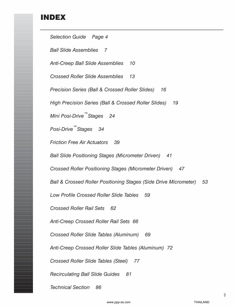
INDEX
Selection Guide Page 4
Ball Slide Assemblies 7
Anti-Creep Ball Slide Assemblies 10
Crossed Roller Slide Assemblies 13
Precision Series (Ball & Crossed Roller Slides) 16
High Precision Series (Ball & Crossed Roller Slides) 19
Mini Posi-Drive™Stages 24
Posi-Drive™Stages 34
Friction Free Air Actuators 39
Ball Slide Positioning Stages (Micrometer Driven) 41
Crossed Roller Positioning Stages (Micrometer Driven) 47
Ball & Crossed Roller Positioning Stages (Side Drive Micrometer) 53
Low Profile Crossed Roller Slide Tables 59
Crossed Roller Rail Sets 62
Anti-Creep Crossed Roller Rail Sets 66
Crossed Roller Slide Tables (Aluminum) 69
Anti-Creep Crossed Roller Slide Tables (Aluminum) 72
Crossed Roller Slide Tables (Steel) 77
Recirculating Ball Slide Guides 81
Technical Section 86
www.ppp-ss.com THAILAND

SelectionGuide
SERIES LOAD TRAVEL LENGTH ACCURACYCAPACITY, LB.
MINI C .75-1.5 0.3-1.5 0.52-1.75 0.0005″/″D-S3 4-205 0.5-12 1.06-15.00 0.0005″/″(51 MODELS)
BALL SLIDES
SERIES LOAD TRAVEL LENGTH ACCURACYCAPACITY, LB.
MINI RD 30-90 0.5-2.0 1.06-3.06 0.0001″/″RE-RS3 48-779 0.5-12.0 1.06-15.00 0.0001″/″(47 MODELS)
CROSSED ROLLER SLIDES
SERIES LOAD TRAVEL LENGTH ACCURACYCAPACITY, LB.
M-2SS-S5-7SS 12-170 1.0-7.0 2.56-9.0 0.0001″/″(17 MODELS)
PRECISION BALL SLIDE SERIES
SERIES LOAD TRAVEL LENGTH ACCURACYCAPACITY, LB.
RS2SS-RS5SS 80-260 1.0-7.0 2.00-9.00 0.0001″/″(12 MODELS)
PRECISION CROSSED ROLLER SLIDE SERIES
SERIES LOAD TRAVEL LENGTH ACCURACYCAPACITY, LB.
HPM-HPS5 8-225 0.5-10.0 1.00-15.00 0.000040″/″(42 MODELS)
HIGH PRECISION SERIES BALL SLIDES (LOW PROFILE & FLANGE BASE)
4
SERIES LOAD TRAVEL LENGTH ACCURACYCAPACITY, LB.
HPRS2-HPRS5 90-450 1.0-10.0 2.00-15.00 0.000040″/″(34 MODELS)
pg 7
pg 13
pg 16
pg 18
pg 19
pg 22
HIGH PRECISION SERIES CROSSED ROLLER SLIDES (LOW PROFILE & FLANGE BASE)
ANTI-CREEP BALL SLIDE ASSEMBLIES
SERIES LOAD TRAVEL LENGTH ACCURACYCAPACITY, LB.
C-AC-S3-AC 1.5-205 .50-12.00 .75-15.00 0.0005″/″pg 10
www.ppp-ss.com THAILAND

SelectionGuide
SERIES LOAD TRAVEL LENGTH ACCURACYCAPACITY, LB.
SERIES LOAD TRAVEL LENGTH ACCURACYCAPACITY, LB.
LS1-1-C125-LS3-12-B10 8-90 1.0-12.0 4.88-21.63 0.0001″/″(36 MODELS)
LRS1-1-C125-LRS3-12-B10 15-180 1.0-12.0 4.88-21.63 0.0001″/″(36 MODELS)
MINI POSI-DRIVE™ & POSI-DRIVE™ STAGES
Friction Free Air Actuator
SERIES LOAD CAPACITY, TRAVEL WORK ACCURACYLB. X, XY, Z SURFACE
R99 40, 40, 1.25 0.25 0.75 x0.75 0.0001″/″
R101-R3204 23-160, 23-160, 1.25-30 0.50-2.00 1.25 x 1.25 to 0.0001″/″(25 MODELS, with micrometers) 5.12 x 5.12
R101P-R3206P 23-160, 23-160 0.50-4.00 1.25 x 1.25 to 0.0001″/″(11 MODELS, X and XY ONLY, no micrometers) 5.12 x 5.12
CROSSED ROLLER POSITIONING STAGES (MICROMETER DRIVEN)INCLUDING SIDE DRIVE CONFIGURATION
SERIES LOAD CAPACITY, TRAVEL WORK ACCURACYLB. X, XY, Z SURFACE
99X 5,5,1.25 0.25 0.75 X 0.75 0.0005″/″
101-3204 4-60, 4-60, 1.25-30 0.50-2.00 1.25 x 1.25 to 0.0005″/″(25 MODELS, with micrometers) 5.12 x 5.12
101P-3206-P 4-60, 4-60 0.50-4.00 1.25 x 1.25 to 0.0005″/″(11 MODELS, X and XY ONLY, no micrometers) 5.12 x 5.12
BALL SLIDE POSITIONING STAGES (MICROMETER DRIVEN)INCLUDING SIDE DRIVE CONFIGURATION
Available with inch or metric micrometers, in X, XY, and XYZ configurations.
Available with inch or metric micrometers, in X, XY, and XYZ configurations.
5
PNRE 1-3 78-94 .50- 2” 3.149- 7.677 0.0001 ″/″
pg 24
pg 39
pg 41
pg 53
pg 53
pg 47
www.ppp-ss.com THAILAND
6
SERIES LOAD TRAVEL LENGTH ACCURACYCAPACITY, LB.
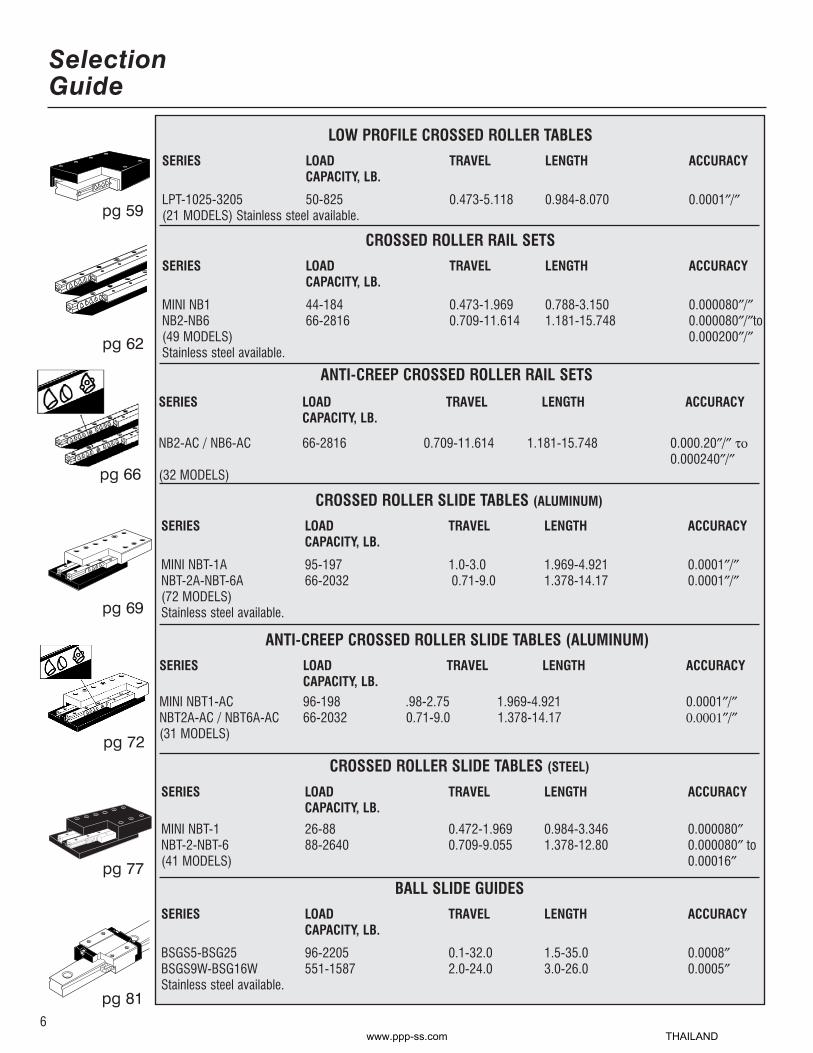
LPT-1025-3205 50-825 0.473-5.118 0.984-8.070 0.0001″/″(21 MODELS) Stainless steel available.
LOW PROFILE CROSSED ROLLER TABLES
SERIES LOAD TRAVEL LENGTH ACCURACYCAPACITY, LB.
MINI NB1 44-184 0.473-1.969 0.788-3.150 0.000080″/″NB2-NB6 66-2816 0.709-11.614 1.181-15.748 0.000080″/″to(49 MODELS) 0.000200″/″Stainless steel available.
CROSSED ROLLER RAIL SETS
SERIES LOAD TRAVEL LENGTH ACCURACYCAPACITY, LB.
MINI NBT-1 26-88 0.472-1.969 0.984-3.346 0.000080″NBT-2-NBT-6 88-2640 0.709-9.055 1.378-12.80 0.000080″ to (41 MODELS) 0.00016″
SERIES LOAD TRAVEL LENGTH ACCURACYCAPACITY, LB.
BSGS5-BSG25 96-2205 0.1-32.0 1.5-35.0 0.0008″BSGS9W-BSG16W 551-1587 2.0-24.0 3.0-26.0 0.0005″Stainless steel available.
SelectionGuide
pg 59
pg 62
pg 77
pg 81
SERIES LOAD TRAVEL LENGTH ACCURACYCAPACITY, LB.
MINI NBT1-AC 96-198 .98-2.75 1.969-4.921 0.0001″/″NBT2A-AC / NBT6A-AC 66-2032 0.71-9.0 1.378-14.17 0.0001″/″(31 MODELS)
ANTI-CREEP CROSSED ROLLER SLIDE TABLES (ALUMINUM)
BALL SLIDE GUIDES
SERIES LOAD TRAVEL LENGTH ACCURACYCAPACITY, LB.
MINI NBT-1A 95-197 1.0-3.0 1.969-4.921 0.0001″/″NBT-2A-NBT-6A 66-2032 0.71-9.0 1.378-14.17 0.0001″/″(72 MODELS)Stainless steel available.pg 69
SERIES LOAD TRAVEL LENGTH ACCURACYCAPACITY, LB.
NB2-AC / NB6-AC 66-2816 0.709-11.614 1.181-15.748 0.000.20″/″ το0.000240″/″
(32 MODELS)
ANTI-CREEP CROSSED ROLLER RAIL SETS
pg 66
CROSSED ROLLER SLIDE TABLES (ALUMINUM)
pg 72
CROSSED ROLLER SLIDE TABLES (STEEL)
www.ppp-ss.com THAILAND

6 Reasons to chooseDel-Tron Ball Slides
Del-TronBall SlidesLoad Ratings and Life EstimatesThe rated load capacity of Del-Tron ball slidesmay be a mass load on a horizontal slide,or aforce load normal to the mounting surface inany position. The rated load must be centered and distributed over the slide, andthe base must be fully supported on a flatmounting surface so that the ball slide doesnot act as a beam subject to concentrated ordistributed bending forces. Loads supportedby protruding arms reduce accuracy and loadcapacity by acting as levers or ratio arms,and should be avoided even when loadforces are small.
When used at the rated load capacity andmoderate speeds, a life of 10 million inches oftravel can be expected.The expected life atone half the rated load is 100 million inches.
Friction and LubricationThe coefficient of friction is lower for linearball bearings than for rotary bearings, wherethe peripheral track is shorter on the innerrace than on the outer race, causing the ballto skid on one or the other. The balls runexactly equal distances on the pair of tracksin linear bearings, permitting the ball to runwithout friction, wear, or skidding at any preload.The typical coefficient of friction forDel-Tron ball slides is 0.003.
Lubrication is recommended for speedsabove 1800 inches/min, and is advisable atlower speeds where high loads are applied incontinuous duty applications.
Mounting and AccuracyThe mounting surfaces of the ball slide aremachined flat and smooth, and parallel toeach other and the line of motion. They mustbe mounted on smooth, flat supports that willnot deflect under load. Especially with longslides of small cross section, binding may becaused by distortion of the bottom memberwhen mounted on irregular surfaces. If so,round shims or spacers may be placed overthe mounting screws to raise the slide abovethe surface asperities. Bedding in epoxy resinis also recommended.
The specified accuracy for all standard Del-Tron ball slides is .0005inch/inch of travel.This is measured by comparison of the line oftravel to a master straight edge, using a gageor indicator mounted on the slide.
7
BALL SLIDES
1. Factory preload adjustment preventssideplay and backlash.
2. Lightweight aluminum carriage andbase with high load capacity.
3. Built-in holes simplify installationand component mounting.
4. Steel shafts, ground over the entirelength, reduce coefficient of frictionto 0.003.
5. Long life, self cleaning ball bearingneeds no lubrication.
6. Mounting surfaces, parallel to theline of motion, provide straight lineaccuracy to 0.0005″″/″″of travel.
®
®®
®
www.ppp-ss.com THAILAND

Ball SlideAssemblies
.33
.50
1.00
1.50
.50
1.00
2.00
3.00
4.00
5.00
.50
1.00
2.00
3.00
4.00
5.00
.50
1.00
1.50
2.00
3.00
.75
1.5
1.5
1.5
4
8
12
14
16
18
8
10
12
14
16
18
10
12
13
15
18
.08
.10
.15
.25
.30
.50
.80
1.1
1.2
1.5
.40
.90
1.3
1.7
2.1
2.5
1.2
1.7
1.9
2.2
5.0
.52
.75
1.25
1.75
1.06
2.06
3.06
4.06
5.06
6.06
1.06
2.06
3.06
4.06
5.06
6.06
1.56
2.56
3.06
3.56
4.56
.23
.23
.23
.23
.32
.32
.32
.32
.32
.32
.41
.41
.41
.41
.41
.41
.50
.50
.50
.50
.50
.38
.38
.38
.38
.56
.56
.56
.56
.56
.56
.75
.75
.75
.75
.75
.75
1.00
1.00
1.00
1.00
1.00
.250
.375
.875
1.375
.625
1.625
2.625
3.625
4.625
5.625
.625
1.625
2.625
3.625
4.625
5.625
1.250
2.250
2.750
3.250
4.250
.156
.156
.156
.156
.218
.218
.218
.218
.218
.218
.375
.375
.375
.375
.375
.375
.437
.437
.437
.437
.437
.135
.135
.135
.135
.187
.187
.187
.187
.187
.187
.250
.250
.250
.250
.250
.250
.250
.250
.250
.250
.250
.156
.156
.156
.156
.250
.250
.250
.250
.250
.250
.375
.375
.375
.375
.375
.375
.500
.500
.500
.500
.500
.250
.375
.875
1.375
.750
1.375
2.375
3.375
3.500
4.500
.750
1.375
2.375
3.375
3.500
4.500
1.250
2.250
2.750
3.250
4.250
MODEL TRAVEL*
LOADCAPACITY
LBWEIGHT
OZLENGTH
AHEIGHT
BWIDTH
CHEIGHT
FWIDTH
G
HOLESPACING
H
CARRIAGEHOLE
SPACING
D E
BASE DIMENSIONS
SERIESCARRIAGE
4 HOLES (I)BASE HOLE d
BASE HOLE D1BASE HOLE h
COUNTER BORESCREW SIZE
C2-56 UNC-2B
THREAD2-56 UNC
--
N/A
D2-56 UNC-2B
THREAD.101.144.100
#2
E4-40 UNC-2B
THREAD.125.198.125
#4
M6-32 UNC-2B
THREAD.125.198.125
#4
N6-32 UNC-2B
THREAD.157.244.150
#6
S16-32 UNC-2B
THREAD.157.244.150
#6
S26-32 UNC-2B
THREAD.157.244.150
#6
S310-32 UNF-2B
THREAD.204.328.205
#10
8
*Travel is 1/2 distance from center in either direction.
moment load ratings + load / life formulas. pg.82
C-.5
C-1
C-2
C-3
D-1
D-2
D-3
D-4
D-5
D-6
E-1
E-2
E-3
E-4
E-5
E-6
M-1
M-2
M-2.5
M-3
M-4
www.ppp-ss.com THAILAND

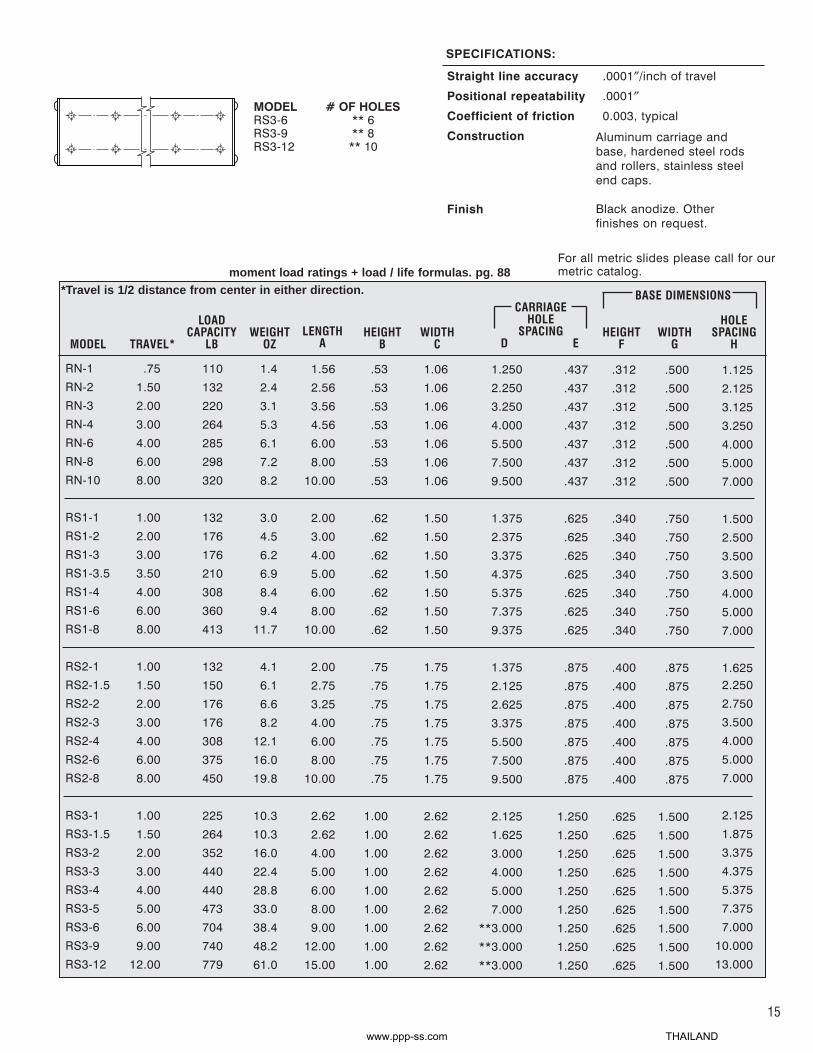
SPECIFICATIONS:
Straight Line Accuracy.0005″/inch of travel
Positional Repeatability.0002″
FinishClear anodize carriage andblack anodize base. Otherfinishes on request.
Coefficient of Friction0.003 typical
ConstructionAluminum carriage and base,hardened steel shafts and balls,mild steel end caps.
For all metric slides please callfor our metric catalog.
MODELS3-6S3-9S3-12
# OF HOLES** 6** 8
** 10
N-1
N-2
N-3
N-4
N-6
N-8
N-10
S1-1
S1-2
S1-3
S1-3.5
S1-4
S1-6
S1-8
S2-1
S2-1.5
S2-2
S2-3
S2-4
S2-6
S2-8
S3-1
S3-1.5
S3-2
S3-3
S3-4
S3-5
S3-6
S3-9
S3-12
.75
1.50
2.00
3.00
4.00
6.00
8.00
1.00
2.00
3.00
3.50
4.00
6.00
8.00
1.00
1.50
2.00
3.00
4.00
6.00
8.00
1.00
1.50
2.00
3.00
4.00
5.00
6.00
9.00
12.00
15
18
20
25
30
35
40
15
20
25
30
35
45
55
20
30
42
52
60
75
90
1.3
2.3
3.0
5.2
6.0
7.0
8.0
2.9
4.3
6.0
6.7
8.2
9.2
11.5
4.0
6.0
6.5
8.0
11.8
15.7
19.5
1.56
2.56
3.56
4.56
6.00
8.00
10.00
2.00
3.00
4.00
5.00
6.00
8.00
10.00
2.00
2.75
3.25
4.00
6.00
8.00
10.00
2.62
2.62
4.00
5.00
6.00
8.00
9.00
12.00
15.00
.53
.53
.53
.53
.53
.53
.53
.62
.62
.62
.62
.62
.62
.62
.75
.75
.75
.75
.75
.75
.75
1.00
1.00
1.00
1.00
1.00
1.00
1.00
1.00
1.00
1.06
1.06
1.06
1.06
1.06
1.06
1.06
1.50
1.50
1.50
1.50
1.50
1.50
1.50
1.75
1.75
1.75
1.75
1.75
1.75
1.75
2.62
2.62
2.62
2.62
2.62
2.62
2.62
2.62
2.62
1.250
2.250
3.250
4.000
5.500
7.500
9.500
1.375
2.375
3.375
4.375
5.375
7.375
9.375
1.375
2.125
2.625
3.375
5.500
7.500
9.500
2.125
1.625
3.000
4.000
5.000
7.000
**3.000
**3.000
**3.000
.437
.437
.437
.437
.437
.437
.437
.625
.625
.625
.625
.625
.625
.625
.875
.875
.875
.875
.875
.875
.875
1.250
1.250
1.250
1.250
1.250
1.250
1.250
1.250
1.250
.312
.312
.312
.312
.312
.312
.312
.340
.340
.340
.340
.340
.340
.340
.400
.400
.400
.400
.400
.400
.400
.625
.625
.625
.625
.625
.625
.625
.625
.625
.500
.500
.500
.500
.500
.500
.500
.750
.750
.750
.750
.750
.750
.750
.875
.875
.875
.875
.875
.875
.875
1.500
1.500
1.500
1.500
1.500
1.500
1.500
1.500
1.500
1.125
2.125
3.125
3.250
4.000
5.000
7.000
1.500
2.500
3.500
3.500
4.000
5.000
7.000
1.625
2.250
2.750
3.500
4.000
5.000
7.000
2.125
1.875
3.375
4.375
5.375
7.375
7.000
10.00013.000
MODEL TRAVEL*
LOADCAPACITY
LBWEIGHT
OZLENGTH
AHEIGHT
BWIDTH
C
CARRIAGEHOLE
SPACINGD E
HEIGHTF
WIDTHG
HOLESPACING
H
BASE DIMENSIONS
30
35
62
88
118
135
150
185
205
10.0
10.0
15.0
20.8
27.2
31.0
35.2
46.5
58.0
9
*Travel is 1/2 distance from center in either direction.moment load ratings + load / life formulas. pg 82
www.ppp-ss.com THAILAND

6 Reasons to chooseDel-Tron® Anti-Creep™™
Ball Slides
Del-Tron®
Anti-Creep™™ SlidesIn certain applications, uneven loads, improperpreload, vertical mounting, or offset forces may causethe ball retainers to become misaligned relative toeach other. The misalignment (“creep”) can ultimatelycause a reduction in overall travel, the need forincreased force to achieve full travel and even failureof the assembly.
Del-Tron’s® Anti-Creep™ retainer design preventsthese problems. The single piece retainer andintegral positive end stops prevent ball retainermisalignment and help keep the rolling elementscentered in the assembly. The retainer is molded ofengineering plastic and slotted in the center. Dowelpins mounted in the base and carriage limit the travelof the retainer and help to keep it centered in theslide for full travel and extended life. In applicationsin which retainer misalignment is a concern, Del-Tron® Anti-Creep™ slides demonstrate greatlyincreased life and improved performance. Anti-Creep™
slides have been extensively tested in Del-Tron’sinternal testing facility and successfully used in thefield for over seven years. If you are concerned thatyour application may induce uneven loads or forcesor if the need for a slide operating vertically exists,consider Del-Tron’s® Anti-Creep™ retainer design.
Anti-Creep Linear Slides
1. Ideal for vertical applications
2. Increased life with overhanging loads
3. Positive internal stops
4. Low friction, straight line design
5. Factory preload controls side playand backlash
6. 0.0005″″/inch straight line accuracy
10
www.ppp-ss.com THAILAND

Anti-Creep LinearSlides
.50
1.00
1.50
.50
1.00
2.00
3.00
4.00
5.00
.50
1.00
2.00
3.00
4.00
5.00
.50
1.00
1.50
2.00
3.00
1.5
1.5
1.5
4
8
12
14
16
18
8
10
12
14
16
18
10
12
13
15
18
.10
.15
.25
.30
.50
.80
1.1
1.2
1.5
.40
.90
1.3
1.7
2.1
2.5
1.2
1.7
1.9
2.2
5.0
.75
1.25
1.75
1.06
2.06
3.06
4.06
5.06
6.06
1.06
2.06
3.06
4.06
5.06
6.06
1.56
2.56
3.06
3.56
4.56
.23
.23
.23
.32
.32
.32
.32
.32
.32
.41
.41
.41
.41
.41
.41
.50
.50
.50
.50
.50
.38
.38
.38
.56
.56
.56
.56
.56
.56
.75
.75
.75
.75
.75
.75
1.00
1.00
1.00
1.00
1.00
.375
.875
1.375
.625
1.625
2.625
3.625
4.625
5.625
.625
1.625
2.625
3.625
4.625
5.625
1.250
2.250
2.750
3.250
4.250
.156
.156
.156
.218
.218
.218
.218
.218
.218
.375
.375
.375
.375
.375
.375
.437
.437
.437
.437
.437
.135
.135
.135
.187
.187
.187
.187
.187
.187
.250
.250
.250
.250
.250
.250
.250
.250
.250
.250
.250
.156
.156
.156
.250
.250
.250
.250
.250
.250
.375
.375
.375
.375
.375
.375
.500
.500
.500
.500
.500
.375
.875
1.375
.750
1.375
2.375
3.375
3.500
4.500
.750
1.375
2.375
3.375
3.500
4.500
1.250
2.250
2.750
3.250
4.250
MODEL TRAVEL*
LOADCAPACITY
LBWEIGHT
OZLENGTH
AHEIGHT
BWIDTH
CHEIGHT
FWIDTH
G
HOLESPACING
H
CARRIAGEHOLE
SPACING
D E
BASE DIMENSIONS
C2-56 UNC-2B
THREAD2-56 UNC
--
N/A
D2-56 UNC-2B
THREAD.101.144.100
#2
E4-40 UNC-2B
THREAD.125.198.125
#4
M6-32 UNC-2B
THREAD.125.198.125
#4
N6-32 UNC-2B
THREAD.157.244.150
#6
S16-32 UNC-2B
THREAD.157.244.150
#6
S26-32 UNC-2B
THREAD.157.244.150
#6
S310-32 UNF-2B
THREAD.204.328.205
#10
11
*Travel is 1/2 distance from center in either direction.
moment load ratings + load / life formulas. pg.88
C-1AC
C-2AC
C-3AC
D-1AC
D-2AC
D-3AC
D-4AC
D-5AC
D-6AC
E-1AC
E-2AC
E-3AC
E-4AC
E-5AC
E-6AC
M-1AC
M-2AC
M-2.5AC
M-3AC
M-4AC
SERIESCARRIAGE
4 HOLES (I)BASE HOLE d
BASE HOLE D1BASE HOLE h
COUNTER BORESCREW SIZE
www.ppp-ss.com THAILAND

12
SPECIFICATIONS:
Straight Line Accuracy.0005″/inch of travel
Positional Repeatability.0002″
FinishClear anodize carriage andblack anodize base. Otherfinishes on request.
Coefficient of Friction0.003 typical
ConstructionAluminum carriage and base,hardened steel shafts and balls,mild steel end caps.
For all metric slides please callfor our metric catalog.
MODELS3-6ACS3-9ACS3-12AC
# OF HOLES** 6** 8
** 10
N-1AC
N-2AC
N-3AC
N-4AC
N-6AC
N-8AC
N-10AC
S1-1AC
S1-2AC
S1-3AC
S1-3.5AC
S1-4AC
S1-6AC
S1-8AC
S2-1AC
S2-1.5AC
S2-2AC
S2-3AC
S2-4AC
S2-6AC
S2-8AC
S3-1AC
S3-1.5AC
S3-2AC
S3-3AC
S3-4AC
S3-5AC
S3-6AC
S3-9AC
S3-12AC
.75
1.50
2.00
3.00
4.00
6.00
8.00
1.00
2.00
3.00
3.50
4.00
6.00
8.00
1.00
1.50
2.00
3.00
4.00
6.00
8.00
1.00
1.50
2.00
3.00
4.00
5.00
6.00
9.00
12.00
15
18
20
25
30
35
40
15
20
25
30
35
45
55
20
30
42
52
60
75
90
1.3
2.3
3.0
5.2
6.0
7.0
8.0
2.9
4.3
6.0
6.7
8.2
9.2
11.5
4.0
6.0
6.5
8.0
11.8
15.7
19.5
1.56
2.56
3.56
4.56
6.00
8.00
10.00
2.00
3.00
4.00
5.00
6.00
8.00
10.00
2.00
2.75
3.25
4.00
6.00
8.00
10.00
2.62
2.62
4.00
5.00
6.00
8.00
9.00
12.00
15.00
.53
.53
.53
.53
.53
.53
.53
.62
.62
.62
.62
.62
.62
.62
.75
.75
.75
.75
.75
.75
.75
1.00
1.00
1.00
1.00
1.00
1.00
1.00
1.00
1.00
1.06
1.06
1.06
1.06
1.06
1.06
1.06
1.50
1.50
1.50
1.50
1.50
1.50
1.50
1.75
1.75
1.75
1.75
1.75
1.75
1.75
2.62
2.62
2.62
2.62
2.62
2.62
2.62
2.62
2.62
1.250
2.250
3.250
4.000
5.500
7.500
9.500
1.375
2.375
3.375
4.375
5.375
7.375
9.375
1.375
2.125
2.625
3.375
5.500
7.500
9.500
2.125
1.625
3.000
4.000
5.000
7.000
**3.000
**3.000
**3.000
.437
.437
.437
.437
.437
.437
.437
.625
.625
.625
.625
.625
.625
.625
.875
.875
.875
.875
.875
.875
.875
1.250
1.250
1.250
1.250
1.250
1.250
1.250
1.250
1.250
.312
.312
.312
.312
.312
.312
.312
.340
.340
.340
.340
.340
.340
.340
.400
.400
.400
.400
.400
.400
.400
.625
.625
.625
.625
.625
.625
.625
.625
.625
.500
.500
.500
.500
.500
.500
.500
.750
.750
.750
.750
.750
.750
.750
.875
.875
.875
.875
.875
.875
.875
1.500
1.500
1.500
1.500
1.500
1.500
1.500
1.500
1.500
1.125
2.125
3.125
3.250
4.000
5.000
7.000
1.500
2.500
3.500
3.500
4.000
5.000
7.000
1.625
2.250
2.750
3.500
4.000
5.000
7.000
2.125
1.875
3.375
4.375
5.375
7.375
7.000
10.00013.000
MODEL TRAVEL*
LOADCAPACITY
LBWEIGHT
OZLENGTH
AHEIGHT
BWIDTH
C
CARRIAGEHOLE
SPACINGD E
HEIGHTF
WIDTHG
HOLESPACING
H
BASE DIMENSIONS
30
35
62
88
118
135
150
185
205
10.0
10.0
15.0
20.8
27.2
31.0
35.2
46.5
58.0
*Travel is 1/2 distance from center in either direction.moment load ratings + load / life formulas. pg 88
www.ppp-ss.com THAILAND

1. Positive stops prevent over travel.
2. Rollers improve load capacity 6-8times that of balls.
3. Precision ground shafts providestraight line accuracy of 0.0001”per inch of travel.
4. Alternately crossed rollers handleforce in any direction.
5. Lightweight aluminum carriage andbase.
6. Interchangeable with many types ofball slides.
6 Reasons to chooseDel-Tron CrossedRoller Slides
Del-TronCrossed RollerSlidesDel-Tron’s new series of crossed roller slides,offer designers additional flexibility in theirchoice of ready to install components forprecision linear transfer.
Our crossed roller slides, when compared toour ball slide products of equal size, offerhigher load carrying capacity and, whenoperating at high cycling rates or with shockand overhanging loads, improved performance. Most importantly, our crossedroller slides provide high accuracy,0.0001″/inch of travel, and repeatability,0.0001″, exceeding our precision ball slides.Although crossed roller slides cost more thanequivalent size ball slides, their overallperformance, especially in applications whereheavy loads must be moved in compactassemblies, often justifies selection.
OperationCrossed roller slides physically resembleball slides except for the bearing design.Specifically, each slide is comprised of analuminum carriage straddling an aluminumbase. Using a bearing system containingcylindrical steel rollers, the carriage glides,almost friction free, over the base.
The rollers, alternately crisscrossed witheach other, move between a set of 4, partially flat, parallel, smooth rods on eachside of the base. The rollers share a largercontact surface with the rods as comparedto the point contact of steel balls. Thisbearing design allows crossed roller slidesto carry larger loads and absorb greaterload impacts than equivalent size ballslides.
Crossed roller slides are not as naturally self-cleaning in operation as ball slides. Inoperating environments, with little or noprotection against dust and when heavyloads are not a consideration, consider Del-Tron’s ball slides.
Wide SelectionDel-Tron offers over 47 models of crossedroller slides. Load capacities range from 30 lb to 779 lb, with travel from 0.5″ to 12″.Installation into your system is simple.Counterbored holes in the base permitquick attachment to your assembly.Components attach to the carriage in theexisting threaded mounting holes.
13
Crossed Roller Slides®
®
www.ppp-ss.com THAILAND

SERIES
CARRIAGE4 HOLES (I)
BASE HOLE d
BASE HOLE D1
BASE HOLE h
COUNTER BORESCREW SIZE
RD
2-56 UNC-2BTHREAD
.101
.144
.100
#2
RM
6-32 UNC-2BTHREAD
.125
.198
.125
#4
RE
4-40 UNC-2BTHREAD
.125
.198
.125
#4
RN
6-32 UNC-2BTHREAD
.157
.244
.150
#6
RS1
6-32 UNC-2BTHREAD
.157
.244
.150
#6
RS2
6-32 UNC-2BTHREAD
.157
.244
.150
#6
RS3
10-32 UNF-2BTHREAD
.204
.328
.205
#10
Crossed RollerSlide Assemblies
RD-1
RD-2
RD-3
RD-4
RD-5
RD-6
RE-1
RE-2
RE-3
RE-4
RE-5
RE-6
RM-1
RM-2
RM-2.5
RM-3
RM-4
.50
1.00
2.00
3.00
4.00
5.00
.50
1.00
2.00
3.00
4.00
5.00
.50
1.00
1.50
2.00
3.00
30
55
66
71
80
90
48
78
94
98
104
108
70
78
78
83
90
0.4
0.6
0.9
1.2
1.3
1.6
0.5
1.0
1.4
1.8
2.2
2.6
1.3
1.8
2.0
2.3
2.8
1.06
2.06
3.06
4.06
5.06
6.06
1.06
2.06
3.06
4.06
5.06
6.06
1.56
2.56
3.06
3.56
4.56
.32
.32
.32
.32
.32
.32
.41
.41
.41
.41
.41
.41
.50
.50
.50
.50
.50
.56
.56
.56
.56
.56
.56
.75
.75
.75
.75
.75
.75
1.00
1.00
1.00
1.00
1.00
.625
1.625
2.625
3.625
4.625
5.625
.625
1.625
2.625
3.625
4.625
5.625
1.250
2.250
2.750
3.250
4.250
.218
.218
.218
.218
.218
.218
.375
.375
.375
.375
.375
.375
.437
.437
.437
.437
.437
.187
.187
.187
.187
.187
.187
.250
.250
.250
.250
.250
.250
.250
.250
.250
.250
.250
.250
.250
.250
.250
.250
.250
.375
.375
.375
.375
.375
.375
.500
.500
.500
.500
.500
.750
1.375
2.375
3.375
3.500
4.500
.750
1.375
2.375
3.375
3.500
4.500
1.250
2.250
2.750
3.250
4.250
MODEL TRAVEL*
LOADCAPACITY
LBWEIGHT
OZLENGTH
AHEIGHT
BWIDTH
C
CARRIAGEHOLE
SPACINGD E
HEIGHTF
WIDTHG
HOLESPACING
H
BASE DIMENSIONS
LOAD RATINGS AND LIFEESTIMATESCrossed roller slide rated load capacities maybe a mass load on a horizontal slide, or aforce load normal to the mounting surface inany position. The rated load must be centeredand distributed over the slide, and the base mustbe supported on a flat mounting surface. Avoid concentrated ordistributed bending forces.
At rated load capacity and moderate speeds,expected life is 10 millioninches of travel. The expected life at one halfthe rated load is 100 million inches.
14
BD1
C
E
G
I
Fh
d
A
D
H
B
LUBRICATIONThe crossed roller slides are lightly lubricated during assembly. Additionallubrication is required for speeds above1200 inches/min. and is advisable at lowerspeeds where high loads are applied incontinuous duty applications.
MOUNTINGMount the crossed roller slides on flatsurfaces to provide full support to the base.
*Travel is 1/2 distance from center in either direction.moment load ratings + load / life formulas. pg. 88
www.ppp-ss.com THAILAND
SPECIFICATIONS:
Straight line accuracy
Positional repeatability
Coefficient of friction
Construction
Finish
.0001″/inch of travel
.0001″
0.003, typical
Aluminum carriage andbase, hardened steel rodsand rollers, stainless steelend caps.
Black anodize. Otherfinishes on request.
For all metric slides please call for ourmetric catalog.
RN-1
RN-2
RN-3
RN-4
RN-6
RN-8
RN-10
RS1-1
RS1-2
RS1-3
RS1-3.5
RS1-4
RS1-6
RS1-8
RS2-1
RS2-1.5
RS2-2
RS2-3
RS2-4
RS2-6
RS2-8
RS3-1
RS3-1.5
RS3-2
RS3-3
RS3-4
RS3-5
RS3-6
RS3-9
RS3-12
.75
1.50
2.00
3.00
4.00
6.00
8.00
1.00
2.00
3.00
3.50
4.00
6.00
8.00
1.00
1.50
2.00
3.00
4.00
6.00
8.00
1.00
1.50
2.00
3.00
4.00
5.00
6.00
9.00
12.00
110
132
220
264
285
298
320
132
176
176
210
308
360
413
132
150
176
176
308
375
450
225
264
352
440
440
473
704
740
779
1.4
2.4
3.1
5.3
6.1
7.2
8.2
3.0
4.5
6.2
6.9
8.4
9.4
11.7
4.1
6.1
6.6
8.2
12.1
16.0
19.8
10.3
10.3
16.0
22.4
28.8
33.0
38.4
48.2
61.0
1.56
2.56
3.56
4.56
6.00
8.00
10.00
2.00
3.00
4.00
5.00
6.00
8.00
10.00
2.00
2.75
3.25
4.00
6.00
8.00
10.00
2.62
2.62
4.00
5.00
6.00
8.00
9.00
12.00
15.00
.53
.53
.53
.53
.53
.53
.53
.62
.62
.62
.62
.62
.62
.62
.75
.75
.75
.75
.75
.75
.75
1.00
1.00
1.00
1.00
1.00
1.00
1.00
1.00
1.00
1.06
1.06
1.06
1.06
1.06
1.06
1.06
1.50
1.50
1.50
1.50
1.50
1.50
1.50
1.75
1.75
1.75
1.75
1.75
1.75
1.75
2.62
2.62
2.62
2.62
2.62
2.62
2.62
2.62
2.62
1.250
2.250
3.250
4.000
5.500
7.500
9.500
1.375
2.375
3.375
4.375
5.375
7.375
9.375
1.375
2.125
2.625
3.375
5.500
7.500
9.500
2.125
1.625
3.000
4.000
5.000
7.000
**3.000
**3.000
**3.000
.437
.437
.437
.437
.437
.437
.437
.625
.625
.625
.625
.625
.625
.625
.875
.875
.875
.875
.875
.875
.875
1.250
1.250
1.250
1.250
1.250
1.250
1.250
1.250
1.250
.312
.312
.312
.312
.312
.312
.312
.340
.340
.340
.340
.340
.340
.340
.400
.400
.400
.400
.400
.400
.400
.625
.625
.625
.625
.625
.625
.625
.625
.625
.500
.500
.500
.500
.500
.500
.500
.750
.750
.750
.750
.750
.750
.750
.875
.875
.875
.875
.875
.875
.875
1.500
1.500
1.500
1.500
1.500
1.500
1.500
1.500
1.500
1.125
2.125
3.125
3.250
4.000
5.000
7.000
1.500
2.500
3.500
3.500
4.000
5.000
7.000
1.6252.250
2.750
3.500
4.000
5.000
7.000
2.125
1.875
3.375
4.375
5.375
7.375
7.000
10.000
13.000
MODEL TRAVEL*
LOADCAPACITY
LBWEIGHT
OZLENGTH
AHEIGHT
BWIDTH
C
CARRIAGEHOLE
SPACINGD E
HEIGHTF
WIDTHG
HOLESPACING
H
BASE DIMENSIONS
15
MODELRS3-6RS3-9RS3-12
# OF HOLES** 6** 8
** 10
*Travel is 1/2 distance from center in either direction.moment load ratings + load / life formulas. pg. 88
www.ppp-ss.com THAILAND

1. Corrosion resistant hardened 400 series stainless steel internal components
2. Up to 5″″ wide cross section.
3. Interchangeable with other manufacturer’s products.
4. Low friction straight line design.
5. Adjustable preload.
6. Straight line design with 0.000050″″repeatability
Precision Series(Ball or Crossed Roller Slides)
Del-Tron’s Precision Series Ball and Roller Slidesoffer the designer an aluminum base and carriagewith hardened stainless components for superiorcorrosion resistance and less chance of particulatecontamination. Available in standard low profilemounting, the designer can choose a style ofbearing and type of rolling element specifically tomeet the needs of the most particular applications.
Preload can be adjusted to change the friction andaxial play characteristics therefore customizing thslide to its intended use. A new 5-inch wide crosssection allows the movement of bulky deviceswithout the necessity of constructing tables withmore than one unit.
6 Reasons to chooseDel-TronPrecision Series(Ball or Crossed Roller Slides)
Precision Series
®
16
www.ppp-ss.com THAILAND

Precision SeriesBall Slides
Model Travel*(in.)
LOAD CAPACITYWeight(lbs.)
Lbs.
1.02.03.0
1.01.52.03.04.0
1.02.03.04.05.06.0
3.05.07.0
122023
2032445462
356492
122139154
92142170
2.563.564.56
2.002.753.254.005.00
2.624.005.006.008.009.00
5.007.009.00
A
---
-----
-----
3.000
2.0003.0004.000
D2
.50
.75
1.00
1.00
B
1.00
1.75
2.62
5.00
C
2.2503.2504.250
1.3752.1252.6253.3754.375
2.1253.0004.0005.0007.0006.000
4.0006.0008.000
D
.125
.157
.204
.281
d
.198
.240
.328
.412
D1
.437
.875
1.250
4.000
E
.25
.40
.61
.61
F
2.2503.2504.250
1.6252.2502.7503.5004.500
2.1253.3754.3755.3757.3757.000
4.0006.0008.000
H
.125
.145
.205
.280
h
#6-32
#6-32
#10-32
1/4-20
I
0.1250.1750.225
0.250.340.410.500.63
0.651.001.251.501.752.25
2.253.254.25
.40
.87
1.50
3.87
G
M-2SSM-3SSM-4SS
S2-1SSS2-1.5SSS2-2SSS2-3SSS2-4SS
S3-1SSS3-2SSS3-3SSS3-4SSS3-5SSS3-6SS
S5-3SSS5-5SSS5-7SS
A
B
D1
C
E
G
I
Fh
d
A
D
H
D2
1
Straight Line Accuracy0.0001″/″ of travel.
Repeatability0.000050″.
Coefficient of Friction0.002.
SPECIFICATIONS:
ConstructionAluminum carriage and base.Hardened 400 series stainless steelballs, shafts, pre-load gibs.Interchangeable with other manufacturers. Economical Ball Slidedesign.
*Travel is 1/2 distance from center in either direction.
moment load ratings + load / life formulas. pg. 88
FinishBlack Anodize. Otherfinishes on request.
17
www.ppp-ss.com THAILAND

Precision SeriesCrossed Roller Slides
Model Travel*(in.)
LOAD CAPACITYWeight(lbs.)
Lbs.
1.02.03.04.0
1.02.03.04.05.0
3.05.07.0
80120130140
210240340380410
220240260
2.003.254.005.00
2.624.005.006.008.00
5.007.009.00
A
----
-----
2.0003.0004.000
D2
.75
1.00
1.00
B
1.75
2.62
5.00
C
1.3752.6253.3754.375
2.1253.0004.0005.0007.000
4.0006.0008.000
D
.157
.204
.281
d
.244
.328
.412
D1
.875
1.250
4.000
E
.40
.61
.61
F
1.6252.7503.5004.500
2.1253.3754.3755.3757.375
4.0006.0008.000
H
.150
.205
.280
h
#6-32
#10-32
1/4-20
I
0.280.460.560.63
0.661.001.251.502.00
2.253.254.25
.87
1.50
3.87
G
RS2-1SSRS2-2SSRS2-3SSRS2-4SS
RS3-1SSRS3-2SSRS3-3SSRS3-4SSRS3-5SS
RS5-3SSRS5-5SSRS5-7SS
A
D1
Fh
d
A
D
H
B
C
E
G
ID2
1
Straight Line Accuracy0.0001″/″ of travel.
Repeatability0.000050″.
Coefficient of Friction0.002.
SPECIFICATIONS:
ConstructionAluminum carriage and base.Hardened 400 series stainless steelrollers, shafts, pre-load gibs.Interchangeable with othermanufacturers. Load capacities up to410 lbs. Crossed Roller design offersself-aligning ways and greater loadcapacity.
*Travel is 1/2 distance from center in either direction.moment load ratings + load / life formulas. pg. 88
FinishBlack Anodize. Otherfinishes on request.
D1
Fh
d
A
D
H
18
www.ppp-ss.com THAILAND

1. Stable flanged base style available
2. Superior accuracy and repeatability.
3. Precision ground carriage and base.
4. Corrosion resistant hardened stainlesssteel internal components.
5. Bigger cross sections and lengths forheavy loads and large moving parts.
6. Smooth low friction motion.
High Precision Series(Ball or Crossed RollerSlides)
Del-Tron’s High Precision Series Ball andCrossed Roller Slides offer the designer highlyaccurate travel characteristics. 0.000040″ perinch of travel with superior repeatability of0.000020″ . The base and carriage innersurfaces are ground to submicron toleranceswhile the mounting surfaces are flat to within0.0001″ per inch.
The standard low profile style incorporates abase which is surrounded by the carriage leaving little surface to attract and hold contaminants. A flanged base style is offered toallow robust mounting at 4 points to assure stability in high impact or rough duty environments.
These slides utilize Del-Tron’s straight linedesign which allows lower friction characteristicsalong with the option to manipulate the preloadto adjust to the needs of the application.
New larger widths and lengths up to 5.75″ wideand 15″ long increase the versatility of thisdesign.
6 Reasons to chooseDel-TronHigh Precision Series(Ball or CrossedRoller Slides)
High Precision Series
®
19
www.ppp-ss.com THAILAND

High Precision SeriesBall Slides(Low Profile)
Straight Line Accuracy0.000040″/″ of travel.
Repeatability0.000020″.
Coefficient of Friction0.002.
HPM-1HPM-2HPM-2.5HPM-3
HPS2-1HPS2-1.5HPS2-2HPS2-3
HPS3-1HPS3-2HPS3-3HPS3-4HPS3-5
HPS4-2HPS4-3HPS4-5HPS4-6.5HPS4-9
HPS5-5HPS5-7HPS5-10
Model Travel*(in.)
LOAD CAPACITYWeight(lbs.)
Lbs.
0.51.01.52.0
1.01.52.03.0
1.02.03.04.05.0
2.03.05.06.59.0
5.07.0
10.0
8152530
25314251
7284
102132145
130140160175200
150180225
0.060.110.160.20
0.280.380.460.56
0.661.001.251.502.00
2.002.884.005.137.00
10.0014.5218.15
1.001.752.503.25
2.002.753.254.00
2.624.005.006.008.00
4.005.758.00
10.2514.00
8.2512.0015.00
A
1.252.002.753.50
2.253.003.504.25
2.624.375.376.378.37
4.506.258.50
10.7514.50
8.7512.5015.50
A1
.500
.750
1.000
1.375
2.000
B
1.00
1.75
2.62
3.50
5.75
C
0.6251.3752.1252.875
1.3752.1252.6253.375
2.1253.0004.0005.0007.000
2.0003.7506.0008.250
12.000
6.25010.00013.000
D
.125
.157
.204
.204
.281
d
.198
.240
.328
.328
.412
D1
CL
0.875
1.250
2.000
4.000
E
0.24
0.40
0.62
0.62
0.98
F
0.40
0.87
1.50
1.98
3.70
G
0.7501.5002.2503.000
1.6252.2502.7503.500
2.1253.3754.3755.3757.375
2.5004.2506.5008.750
12.500
6.25010.00013.000
H
.125
.145
.205
.205
.280
h
#4-40
#6-32
#10-32
#10-32
1/4-20
I
A
D1
Fh
d
A
D
H
1
SPECIFICATIONS:
ConstructionAluminum carriage and base.Hardened 400 series stainless steelballs, shafts, pre-load gibs.Interchangeable with other manufacturers. Carriage and baseground to optical flatness. Bearingway surfaces held to submicrontolerances. Carriage surface flat to0.0001″/″. Ball Slide design offers lowrolling resistance and economicalprice.
*Travel is 1/2 distance from center in either direction.moment load ratings + load / life formulas. pg. 88
FinishBlack Anodize. Otherfinishes on request.
20
HPM SERIES ONLY
www.ppp-ss.com THAILAND

High Precision SeriesBall Slides(Flange Base)
Model Travel*(in.)
LOAD CAPACITYWeight(lbs.)
Lbs.
0.51.01.52.0
1.01.52.03.0
1.02.03.04.05.0
2.03.05.06.59.0
5.07.0
10.0
8152530
25314251
7284
102132145
130140160175200
150180225
0.080.140.200.26
0.380.520.610.75
0.911.401.752.102.80
2.503.595.006.418.75
12.0017.4021.76
1.001.752.503.25
2.002.753.254.00
2.624.005.006.008.00
4.005.758.00
10.2514.00
8.2512.0015.00
A
1.252.002.753.50
2.253.003.504.25
2.624.375.376.378.37
4.506.258.50
10.7514.50
8.7512.5015.50
A1
.750
1.031
1.375
1.750
2.375
B
1.00
1.75
2.62
3.50
5.75
C
0.6251.3752.1252.875
1.3752.1252.6253.375
2.1253.0004.0005.0007.000
2.0003.7506.0008.250
12.000
6.25010.00013.000
D
.125
.157
.204
.204
.281
d
.198
.240
.328
.328
.412
D1
CL
0.875
1.250
2.000
4.000
E
0.50
0.68
1.00
0.99
1.35
F
0.750
1.312
2.062
2.750
5.000
H1
0.7501.5002.2503.000
1.6252.2502.7503.500
2.1253.3754.3755.3757.375
2.5004.2506.5008.750
12.500
6.25010.00013.000
H
.125
.145
.205
.205
.280
h
HPM-1FBHPM-2FBHPM-2.5FBHPM-3FB
HPS2-1FBHPS2-1.5FBHPS2-2FBHPS2-3FB
HPS3-1FBHPS3-2FBHPS3-3FBHPS3-4FBHPS3-5FB
HPS4-2FBHPS4-3FBHPS4-5FBHPS4-6.5FBHPS4-9FB
HPS5-5FBHPS5-7FBHPS5-10FB
#4-40
#6-32
#10-32
#10-32
1/4-20
I
0.25
0.28
0.37
0.37
0.37
K
A
D1
Fh
d
A
D
H
1
Straight Line Accuracy0.000040″/″ of travel.
Repeatability0.000020″.
Coefficient of Friction0.002.
ConstructionAluminum carriage and base.Hardened 400 series stainless steelballs, shafts, pre-load gibs.Interchangeable with other manufacturers. Carriage and baseground to optical flatness. Bearingway surfaces held to submicron tolerances. Carriage surface flat to0.0001″/″. Flange Base design allowsease of mounting and stability.
SPECIFICATIONS:
*Travel is 1/2 distance from center in either direction.moment load ratings + load / life formulas. pg 88
FinishBlack Anodize. Otherfinishes on request.
21
HPM SERIES ONLY
www.ppp-ss.com THAILAND

High Precision SeriesCrossed Roller Slides(Low Profile)
Model Travel*(in.)
LOAD CAPACITYWeight(lbs.)
Lbs.
1.01.52.03.0
1.02.03.04.05.0
2.03.05.06.59.0
5.07.0
10.0
90115130140
220250350390420
260280320350400
300360450
2.002.753.254.00
2.624.005.006.008.00
4.005.758.00
10.2514.00
8.2512.0015.00
A
2.253.003.504.25
2.624.375.376.378.37
4.506.258.50
10.7514.50
8.7512.5015.50
A1
.750
1.000
1.375
2.000
B
1.75
2.62
3.50
5.75
C
1.3752.1252.6253.375
2.1253.0004.0005.0007.000
2.0003.7506.0008.250
12.000
6.25010.00013.000
D
.157
.204
.204
.281
d
.244
.328
.328
.412
D1
0.875
1.250
2.000
4.000
E
0.40
0.62
0.62
0.98
F
1.6252.2502.7503.500
2.1253.3754.3755.3757.375
2.5004.2506.5008.750
12.500
6.25010.00013.000
H
.145
.205
.205
.280
h
#6-32
#10-32
#10-32
1/4-20
I
HPRS2-1HPRS2-1.5HPRS2-2HPRS2-3
HPRS3-1HPRS3-2HPRS3-3HPRS3-4HPRS3-5
HPRS4-2HPRS4-3HPRS4-5HPRS4-6.5HPRS4-9
HPRS5-5HPRS5-7HPRS5-10
0.280.380.460.56
0.661.001.251.502.00
2.002.884.005.137.00
10.0014.5218.15
0.87
1.50
1.98
3.70
G
A
B
D1
C
E
G
I
Fh
d
A
D
H
1
Straight Line Accuracy0.000040″/″ of travel.
Repeatability0.000020″.
Coefficient of Friction0.002.
SPECIFICATIONS:
ConstructionAluminum carriage and base.Hardened 400 series stainless steelrollers, shafts, pre-load gibs.Interchangeable with other manufacturers. Carriage and baseground to optical flatness. Bearingway surfaces held to submicrontolerances. Carriage surface flat to0.0001″/″. Crossed Roller designgreatly increases load capacity andoverhung load capability.
*Travel is 1/2 distance from center in either direction.moment load ratings + load / life formulas. pg. 88
FinishBlack Anodize. Otherfinishes on request.
22
www.ppp-ss.com THAILAND

High Precision SeriesCrossed Roller Slides(Flange Base)
Model Travel*(in.)
LOAD CAPACITYWeight(lbs.)
Lbs.
1.01.52.03.0
1.02.03.04.05.0
2.03.05.06.59.0
5.07.0
10.0
90115130140
220250350390420
260280320350400
300360450
2.002.753.254.00
2.624.005.006.008.00
4.005.758.00
10.2514.00
8.2512.0015.00
A
2.253.003.504.25
2.624.375.376.378.37
4.506.258.50
10.7514.50
8.7512.5015.50
A1
1.031
1.375
1.750
2.375
B
1.75
2.62
3.50
5.75
C
1.3752.1252.6253.375
2.1253.0004.0005.0007.000
2.0003.7506.0008.250
12.000
6.25010.00013.000
D
.157
.204
.204
.281
d
.240
.328
.328
.412
D1
0.875
1.250
2.000
4.000
E
0.68
1.00
.99
1.35
F
1.6252.2502.7503.500
2.1253.3754.3755.3757.375
2.5004.2506.5008.750
12.500
6.25010.00013.000
H
.145
.205
.205
.280
h
#6-32
#10-32
#10-32
1/4-20
I
0.380.520.610.75
0.911.401.752.102.80
2.503.595.006.418.75
12.0017.4021.76
0.28
0.37
0.37
0.37
K
HPRS2-1FBHPRS2-1.5FBHPRS2-2FBHPRS2-3FB
HPRS3-1FBHPRS3-2FBHPRS3-3FBHPRS3-4FBHPRS3-5FB
HPRS4-2FBHPRS4-3FBHPRS4-5FBHPRS4-6.5FBHPRS4-9FB
HPRS5-5FBHPRS5-7FBHPRS5-10FB
1.312
2.062
2.750
5.000
H1
A
B
D1
C
E I
Fh
d
A
D
H
H
K
1
1
Straight Line Accuracy0.000040″/″ of travel.
Repeatability0.000020″.
Coefficient of Friction0.002.
SPECIFICATIONS:
ConstructionAluminum carriage and base.Hardened 400 series stainless steelrollers, shafts, pre-load gibs.Interchangeable with other manufacturers. Carriage and baseground to optical flatness. Bearingway surfaces held to submicron tolerances. Carriage surface flat to0.0001″/″. Flange Base with crossedroller design offers the ultimate inaccuracy, capacity and stability.
*Travel is 1/2 distance from center in either direction.moment load ratings + load / life formulas. pg. 88
FinishBlack Anodize. Otherfinishes on request.
23
www.ppp-ss.com THAILAND

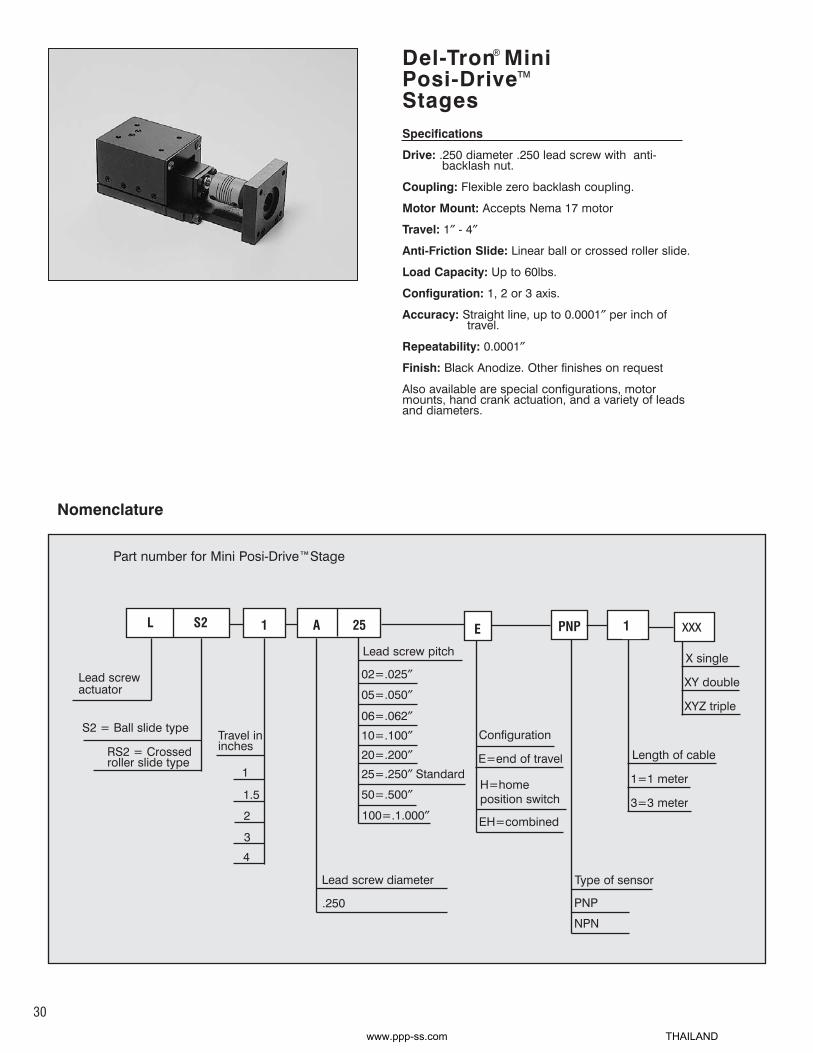
Del-Tron MiniPosi-DriveStages
Compact Posi-Drive™series LS1 and LRS1stages have a height of only 1.250 inch and awidth of only 1.380 inch. These stages provide the same outstanding 0.0001 inchstraight line accuracy per inch of travel and0.0001 inch repeatability as the larger LS3series Posi-Drive™line. The new smallerstages also offer a compact, flexibleconfiguration and are adaptable to standardNema configurations.
The LS1 Posi-Drive™stages offer a .168 inchdiameter .125 lead screw, an anti-backlashnut and a flexible zero backlash coupling thataccepts a Nema 14 motor. They provide aload-carrying capacity of up to 40 pounds.The stages are available in travel lengthsranging from 1 inch to 4 inches. Del-Tron alsoprovides special configurations, motormounts, hand crank actuation and a variety ofleads and pitches.
The new positioners are available with eitherlinear ball or crossed roller slides and can beconfigured for one, two, or three-axis positioning. In the ball slide version, precisionsteel balls roll in the raceway grooves withcontact at four points, enabling load andmoment to be carried on all directions.Rolling resistance is extremely low, ensuringsmooth and stable operation. Crossed rollerslides physically resemble ball slides exceptfor the bearing design. The rollers share alarger contact surface with the rods as compared to the point contact of steel balls.This bearing design allows crossed rollerslides to carry larger loads and absorbgreater load impacts than equivalent size ballslides.
6 Reasons to chooseDel-Tron Mini Posi-Drive™Stages(LS1, LRS1 Series)
Mini Posi-Drive Stages
1. Positive lead screw drive.
2. Zero backlash.
3. Friction-free linear ball or roller slides.
4. Accurate, repeatable linear travel.
5. Compact adaptable configuration.
6. Adaptable to standard NemaConfigurations.
™
®
®™
24
www.ppp-ss.com THAILAND

L
Lead screw actuator
S1
S1 = Ball slide type
RS1 = Crossed roller slide typeTravel ininches
1
2
3
4
Lead screw diameter
.168″
Lead screw pitch
024=.024″
050=.050″
096=.096″125=.125″ Standard
188=.188″250=.250″
375=.375″
1 C 125
Nomenclature
Specifications
Drive: .168 diameter .125 lead screw with anti-backlash nut.
Coupling: Flexible zero backlash coupling.
Motor Mount: Accepts Nema 14 motor
Travel: 1″ - 4″
Anti-Friction Slide: Linear ball or crossed roller slide.
Load Capacity: Up to 40lbs.
Configuration: 1, 2 or 3 axis.
Accuracy: Straight line, up to 0.0001″ per inch oftravel.
Repeatability: 0.0001″
Finish: Black Anodize. Other finishes on request
Also available are special configurations, motormounts, hand crank actuation, and a variety of leadsand diameters .
Del-Tron®® MiniPosi-Drive™™
Stages
Part number for Mini Posi-Drive™Stage
X single
XY double
XYZ triple
xxx
25
Configuration
E=end of travel
H=home position switch
EH=combined
Type of sensor
PNP
NPN
E PNP
Length of cable
1=1 meter
3=3 meter
1
www.ppp-ss.com THAILAND

LRS1-1-C125LRS1-2-C125LRS1-3-C125LRS1-4-C125
1″2″3″4″
1.3752.3753.3755.375
1.5002.5003.5004.000
Roller Slide Mini Posi-Drive Travel* HD
15203040
LoadCapacity
LB
LS1-1-C125LS1-2-C125LS1-3-C125LS1-4-C125
1″2″3″4″
2.0003.0004.0006.000
1.3752.3753.3755.375
1.5002.5003.5004.000
Ball SlideMini Posi-Drive
Travel* HD
.310
.8101.3102.310
1.190.690.990.990
SLB
2.072.072.072.32
C
4.075.076.078.32
A
2.0003.0004.0006.000
B
2.072.072.072.32
C
4.075.076.078.32
A
8101520
LoadCapacity
LB
*Travel is 1/2 distance from center in either direction.moment load ratings + load / life formulas. pg. 88
*Travel is 1/2 distance from center in either direction.moment load ratings + load / life formulas. pg. 88
™
™
Lead: .024″, .050″, .096″
Maximum RecommendedRevolutions Per Second
20 RPS
10 RPSLead: .125″, .188″, .250″, .375″
.310
.8101.3102.310
1.190.690.990.990
SL
26
www.ppp-ss.com THAILAND

27
Mini Posi-Drive™™ Series LS1, LRS1Designed for NEMA 14 motor frame, other motor adaptors available. Supplied with coupling for .1968″(5mm) motor shaft.Couplings with inch and metric bore available. Uses .168″ diameter leadscrew with anti-backlash nut. Standard lead is .125″.Leads available at no additional cost .024″, .050″, .096″, .188″, .250″, and .375″. Standard travels of 1, 2, 3, and 4″
A
B
D
C
1.380
1.000
.500
1.250.030
.250
H
1.380
1.024
.690
1.380
1.024
.690
.866 Dia. Pilotfor 14 Frame Motor
.125 Dia. Thru - 4 plcs
.197 Dia. Borein Coupling
.500 Dia. O.D.of Coupling
C'Bore for #6 Screw - 4 plcs
#6-32 Thread Thru - 4 plcs
www.ppp-ss.com THAILAND

LIMIT AND POSITION SWITCHESEOT (End Of Travel) and HPS (Home Position Switches)Del-Tron Precision offers the addition of EOT and HPS to all 3 sizes of the Posi-Drive series. The EOT kitand the HPS kit could be used together or independently. The stand alone kits can be added to any of the3 sizes of the Posi-Drive series. The EOT kit comes with 2 switches mounted to the base at each end.There are 2 flags that are mounted to the carriage. These flags are adjustable for either the full range oftravel or for limited amount of travel if the application requires such. The Home Position Switch kit comeswith 1 switch mounted to the base in the center. There is an adjustable flag mounted to the carriage. Theadjustable flag will allow the Home Position to be set anywhere along the entire range of travel.The EOT and HPS are easily mounted to brackets, which are then attached to the base. The flags areeasily assembled to a bracket that is then attached to the carriage. The base and carriage have thethreaded mounting holes available for easy assembly of the brackets. The switches are photoelectricsensors that operate on a supply voltage of 5 to 24 VDC. The repeatability is .0002" and the response timeis 100μseconds. The sensors are available in both NPN and PNP outputs. The sensors are equipped witha quick fitting Hook-Up Connector with cable lengths in 1m or 3m.Part Numbering System for EOT and HPS
E-PNP-1X-XXX-X
X-Configuration- E=EOT, H=HPS, EH=CombinedXXX=Type of Sensor, PNP or NPNX=Length of Cable, 1=1meter, 3= 3 meter
Part Number and Price ListE-PNP-1 $119E-NPN-1 $119H-PNP-1 $59H-NPN-1 $59EH-PNP-1 $179EH-NPN-1 $179
Prices are the same for the 3 meterlength cable and connector.
LS1 and LRS1 SERIES
TRAVEL B J
1 2.000 1.5002 3.000 2.5003 4.000 3.5004 6.000 5.500
28
www.ppp-ss.com THAILAND

Del-Tron MiniPosi-DriveStages
Compact Posi-Drive™series LS2 and LRS2stages have a height of only 1.650 inch and awidth of only 1.750 inch. These stages provide the same outstanding 0.0001 inchstraight line accuracy per inch of travel and0.0001 inch repeatability as the larger LS3series Posi-Drive™line. The new smallerstages also offer a compact, flexibleconfiguration and are adaptable to standardNema configurations.
The LS2 Posi-Drive™stages offer a 0.250 inchdiameter .250 lead screw, an anti-backlashnut and a flexible zero backlash coupling thataccepts a Nema 17 motor. They provide aload-carrying capacity of up to 60 pounds.The stages are available in travel lengthsranging from 1 inch to 4 inches. Del-Tron alsoprovides special configurations, motormounts, hand crank actuation and a variety ofleads and pitches.
The new positioners are available with eitherlinear ball or crossed roller slides and can beconfigured for one, two, or three-axis positioning. In the ball slide version, precisionsteel balls roll in the raceway grooves withcontact at four points, enabling load andmoment to be carried on all directions.Rolling resistance is extremely low, ensuringsmooth and stable operation. Crossed rollerslides physically resemble ball slides exceptfor the bearing design. The rollers share alarger contact surface with the rods as compared to the point contact of steel balls.This bearing design allows crossed rollerslides to carry larger loads and absorbgreater load impacts than equivalent size ballslides.
6 Reasons to chooseDel-Tron Mini Posi-Drive™Stages(LS2, LRS2 Series)
29
Mini Posi-Drive Stages
1. Positive lead screw drive.
2. Zero backlash.
3. Friction-free linear ball or roller slides.
4. Accurate, repeatable linear travel.
5. Compact adaptable configuration.
6. Adaptable to standard NemaConfigurations.
™
®
®
www.ppp-ss.com THAILAND
Specifications
Drive: .250 diameter .250 lead screw with anti-backlash nut.
Coupling: Flexible zero backlash coupling.
Motor Mount: Accepts Nema 17 motor
Travel: 1″ - 4″
Anti-Friction Slide: Linear ball or crossed roller slide.
Load Capacity: Up to 60lbs.
Configuration: 1, 2 or 3 axis.
Accuracy: Straight line, up to 0.0001″ per inch oftravel.
Repeatability: 0.0001″
Finish: Black Anodize. Other finishes on request
Also available are special configurations, motormounts, hand crank actuation, and a variety of leadsand diameters.
Del-Tron MiniPosi-DriveStages
30
™
L
Lead screw actuator
S2
S2 = Ball slide type
RS2 = Crossed roller slide type
Travel in inches
1
1.5
2
3
4
Lead screw diameter
.250
Lead screw pitch
02=.025″
05=.050″
06=.062″10=.100″20=.200″25=.250″ Standard
50=.500″
100=.1.000″
1 A 25
Part number for Mini Posi-Drive™Stage
X single
XY double
XYZ triple
xxx
®
Nomenclature
Configuration
E=end of travel
H=homeposition switch
EH=combined
Type of sensor
PNP
NPN
E PNP
Length of cable
1=1 meter
3=3 meter
1
www.ppp-ss.com THAILAND

LRS2-1-A25LRS2-1.5-A25LRS2-2-A25LRS2-3-A25LRS2-4-A25
1″1.5″2″3″4″
4.885.636.136.888.63
2.253.003.504.256.00
1.3752.1252.7503.3755.500
1.6252.2502.7503.5004.000
Roller Slide Mini Posi-Drive Travel* A HD
.250
.625
.8751.2502.125
1.6501.2751.025.650
1.775
SLB
2030405060
LoadCapacity
LB
LS2-1-A25LS2-1.5-A25LS2-2-A25LS2-3-A25LS2-4-A25
Lead: .025″, .050″, .062″, .100″
Maximum RecommendedRevolutions Per Second
20 RPS
10 RPSLead: .200″, .250″, .500″, 1.0″
1″1.5″2″3″4″
4.885.636.136.888.63
2.253.003.504.256.00
1.3752.1252.7503.3755.500
1.6252.2502.7503.5004.000
Ball SlideMini Posi-Drive
Travel* A HDB
1015202530
LoadCapacity
LB
*Travel is 1/2 distance from center in either direction.moment load ratings + load / life formulas. pg. 88
*Travel is 1/2 distance from center in either direction.moment load ratings + load / life formulas. pg. 88
™
™
.250
.625
.8751.2502.125
1.6501.2751.025.650
1.775
SL
31
www.ppp-ss.com THAILAND

C'Bore for #6Screw - 4 Places
H
1.650.281
.040
A2.630
DB
.8751.312
1.750
#6-32 ThreadThru - 4 Places1.750
1.6501.220
.875
1.6501.220
.825.500 Dia. Clearance
.865 Dia. Pilot for17 Frame Motor
.750 Dia. O.D.of Coupling
.250 Dia. Borein Coupling
.136 Dia. Thru - 4 Places
Mini Posi-Drive Series LS2, LRS2Designed for NEMA 17 motor frame, other motor adaptors available. Supplied with coupling for 5mm motor shaft. Couplingswith inch and metric bore available. Uses .250″ diameter leadscrew with anti-backlash nut. Standard lead is .250″. Leads available at no additional cost .025″, .050″, .062″, .100″, .200″, .250″, .500″, and 1.00″. Standard travels of 1, 1.5, 2, 3, and 4″
5mm Bore
™
32
www.ppp-ss.com THAILAND

33
LIMIT AND POSITION SWITCHESEOT (End Of Travel) and HPS (Home Position Switches)Del-Tron Precision offers the addition of EOT and HPS to all 3 sizes of the Posi-Drive series. The EOT kitand the HPS kit could be used together or independently. The stand alone kits can be added to any of the3 sizes of the Posi-Drive series. The EOT kit comes with 2 switches mounted to the base at each end.There are 2 flags that are mounted to the carriage. These flags are adjustable for either the full range oftravel or for limited amount of travel if the application requires such. The Home Position Switch kit comeswith 1 switch mounted to the base in the center. There is an adjustable flag mounted to the carriage. Theadjustable flag will allow the Home Position to be set anywhere along the entire range of travel.The EOT and HPS are easily mounted to brackets, which are then attached to the base. The flags areeasily assembled to a bracket that is then attached to the carriage. The base and carriage have thethreaded mounting holes available for easy assembly of the brackets. The switches are photoelectricsensors that operate on a supply voltage of 5 to 24 VDC. The repeatability is .0002" and the response timeis 100μseconds. The sensors are available in both NPN and PNP outputs. The sensors are equipped witha quick fitting Hook-Up Connector with cable lengths in 1m or 3m.Part Numbering System for EOT and HPS
E-PNP-1X-XXX-X
X-Configuration- E=EOT, H=HPS, EH=CombinedXXX=Type of Sensor, PNP or NPNX=Length of Cable, 1=1meter, 3= 3 meter
Part Number and Price ListE-PNP-1 $119E-NPN-1 $119H-PNP-1 $59H-NPN-1 $59EH-PNP-1 $179EH-NPN-1 $179
Prices are the same for the 3 meterlength cable and connector.
LS2 and LRS2 SERIES
TRAVEL B J
1 2.250 1.6251.5 3.000 2.3752 3.500 2.8753 4.250 3.6254 6.000 5.375
www.ppp-ss.com THAILAND

Del-Tron®®
Posi-Drive™™
Stages
Compact, economical Posi-Drive™stages fromDel-Tron take the work out of designingmotion control systems.Our stages require no alignment of components, install with only fourstandard fasteners, are fitted withanti-backlash lead screws, multi-beamcouplings with high speed misalignmentcapability and standard NEMA motor mounts.
Available in one, two or three axis configurations with either ball or crossedroller slides, these stages travel up to 12″.Thecrossed roller slide option increases loadcapacity up to 180 lbs. and 100 million inchesof travel is possible at 1/2 rated load.
6 Reasons to chooseDel-Tron Posi-DriveStages
Posi-Drive Stages
1. Positive lead screw drive.
2. Zero backlash.
3. Friction-free linear ball or roller slides.
4. Accurate, repeatable linear travel.
5. Compact adaptable configuration.
6. Adaptable to standard Nema Configurations.
™
™®
34
www.ppp-ss.com THAILAND

Specifications
Drive: 3/8″ diameter 0.10 lead screw with anti-backlash nut.
Coupling: Flexible zero backlash coupling.
Motor Mount: Accepts Nema 23 motor
Travel: 1″ - 12″
Anti-Friction Slide: Linear ball or crossed rollerslide.
Load Capacity: Up to 180lbs.
Configuration: 1, 2 or 3 axis.
Accuracy: Straight line, up to 0.0001″ per inch oftravel.
Repeatability: 0.0001″
Finish: Black Anodize. Other finishes on request
Also available are special configurations, motor mounts,and hand crank actuation. A variety of leads anddiameters. Are available at no additional cost.
Del-TronPosi-DriveStages
™®
L
Lead screw actuator
S3
S3 = Ball slide type
RS3 = Crossedroller slide type
Travel ininches
Lead screwdiameter
.375
Lead screw pitch
05=.050″
06=.0625″
10=.100″ Standard
12=.125″20=.200″25=.250″
50=.500″100=1.000″
1 B 10
Nomenclature
Part number for Posi-Drive™Stage
X single
XY double
XYZ triple
xxx
35
1
2
3
4
6
8
10
12
Configuration
E=end of travel
H=homeposition switch
EH=combined
Type of sensor
PNP
NPN
E PNP
Length of cable
1=1 meter
3=3 meter
1
www.ppp-ss.com THAILAND

MODEL
LS3-1-B10
LS3-2-B10
LS3-3-B10
LS3-4-B10
LS3-6-B10
LS3-8-B10
LS3-10-B10
LS3-12-B10
LRS3-1-B10
LRS3-2-B10
LRS3-3-B10
LRS3-4-B10
LRS3-6-B10
LRS3-8-B10
LRS3-10-B10
LRS3-12-B10
A
5.63
6.63
7.63
8.63
12.63
15.63
18.63
21.63
5.63
6.63
7.63
8.63
12.63
15.63
18.63
21.63
B
3.00
4.00
5.00
6.00
9.00
11.00
13.00
15.00
3.00
4.00
5.00
6.00
9.00
11.00
13.00
15.00
D
2.125
3.000
4.000
5.000
2.125
3.000
4.000
5.000
P
10
12
14
14
10
12
14
14
E
2.63
2.63
2.63
2.63
3.63
4.63
5.63
6.63
2.63
2.63
2.63
2.63
3.63
4.63
5.63
6.63
F
0.44
0.50
0.50
0.50
1.50
1.00
0.50
1.50
0.44
0.50
0.50
0.50
1.50
1.00
0.50
1.50
G
0.50
1.00
1.50
2.00
3.50
4.50
5.50
6.50
0.50
1.00
1.50
2.00
3.50
4.50
5.50
6.50
H
2.375
2.375
2.375
2.375
4.000
6.000
8.000
10.000
2.3750
2.3750
2.3750
2.3750
4.0000
6.0000
8.0000
10.0000
H1
0
3.375
4.375
5.375
7.000
9.000
11.000
13.000
0
3.375
4.375
5.375
7.000
9.000
11.000
13.000
J
0.00
0.31
0.31
0.31
1.00
1.00
1.00
1.00
0.00
0.31
0.31
0.31
1.00
1.00
1.00
1.00
K
0.31
0.82
1.31
1.81
2.50
2.50
2.50
2.50
0.31
0.82
1.31
1.81
2.50
2.50
2.50
2.50
Posi-Drive
L
0.188
0.688
1.188
1.688
3.188
4.188
5.188
6.188
0.188
0.688
1.188
1.688
3.188
4.188
5.188
6.188
M
0
0
0
0
0.375
0.375
0.375
0.375
0
0
0
0
0.375
0.375
0.375
0.375
N
3.731
3.731
3.731
3.731
4.106
4.106
4.106
4.106
3.731
3.731
3.731
3.731
4.106
4.106
4.106
4.106
R
0.32
0.32
0.32
0.75
1.75
2.75
3.75
4.75
0.32
0.32
0.32
0.75
1.75
2.75
3.75
4.75
S
2.06
1.56
1.06
0.56
-0.94
-1.94
-2.94
-3.94
2.06
1.56
1.06
0.56
-0.94
-1.94
-2.94
-3.94
MODEL
LS3-1-B10
LS3-2-B10
LS3-3-B10
LS3-4-B10
LS3-6-B10
LS3-8-B10
LS3-10-B10
LS3-12-B10
LRS3-1-B10
LRS3-2-B10
LRS3-3-B10
LRS3-4-B10
LRS3-6-B10
LRS3-8-B10
LRS3-10-B10
LRS3-12-B10
TRAVEL*
INCHES
1
2
3
4
6
8
10
12
1
2
3
4
6
8
10
12
LOAD
CAPACITY
LB.
30
35
40
45
55
60
75
90
60
70
80
90
110
120
150
180
Posi-Drive
*Travel is 1/2 distance from center in either direction.moment load ratings + load / life formulas. pg. 88
™
™
Designed for NEMA 23 motor frame. Supplied with coupling for 0.250” motor shaft. Uses 3/8” diameter lead-screw with anti-backlash nut. Standard lead is 0.10”.Standard travels of 1” - 12”Other motor adapters and coupling with inch and metric bore available as special order.Leads available in 0.050”, 0.0625”, 0.100”, 0.125”, 0.200”, 0.250”, 0.500”, 1.000” and 1.250”
Lead: .050″, .0625″, .100″
Maximum RecommendedRevolutions Per Second
20 RPS
10 RPSLead: .125″, .200″, .250″, .500″, 1.0″
36
www.ppp-ss.com THAILAND

2.000DB
AE
FG
2.6252.3751.250
10-32 Thread8 Places
.7501.750
2.0002.625
.313HH1B
KJ C'Bore for #10
Socket Hd Cap Screw8 Places(1" Travel, 4Places)
Carriage Dimensions for Posi-Driveswith 1 - 4" of Travel
Carriage Dimensions for Posi-Driveswith 6 - 12" of Travel
AB
3.0002.000
3.000G
10-32 Thread"L" Places
2.250
2.625
.188
2.250
1.125
.269
2.625 Dia. B.C.10-32 Thread
4 Places
.250 Bore ofcoupling forNEMA 23 Motor
F
″P″ PLACES
B
2.250
A
E
R
L
1.750
1.750
M
S (+) Z Axis ExtendsBeyond X AxisS (-) Z Axis is Inside X Axis
Y Axis Adaptor Plate for6, 8, 10 & 12" of travel
LX Axis
Y Axis
Z Axis Bracket
Z Axis iscentered
over Y Axis
Motor Centerline of Z Axisis in Same Plane as Motor
Centerline of X Axis
BA
E
N
ABE
L
2.625
Y Axis
1.750
1.750M
L 2.625
Y Axis Adaptor Plate for6, 8, 10 & 12" of travel
X Axis
Carriage Dimensions for Posi-Drive™with 1 - 4″ of Travel
Carriage Dimensions for Posi-Drive™with 6 - 12″ of Travel
37
www.ppp-ss.com THAILAND

LIMIT AND POSITION SWITCHESEOT (End Of Travel) and HPS (Home Position Switches)Del-Tron Precision offers the addition of EOT and HPS to all 3 sizes of the Posi-Drive series. The EOT kitand the HPS kit could be used together or independently. The stand alone kits can be added to any of the3 sizes of the Posi-Drive series. The EOT kit comes with 2 switches mounted to the base at each end.There are 2 flags that are mounted to the carriage. These flags are adjustable for either the full range oftravel or for limited amount of travel if the application requires such. The Home Position Switch kit comeswith 1 switch mounted to the base in the center. There is an adjustable flag mounted to the carriage. Theadjustable flag will allow the Home Position to be set anywhere along the entire range of travel.The EOT and HPS are easily mounted to brackets, which are then attached to the base. The flags areeasily assembled to a bracket that is then attached to the carriage. The base and carriage have thethreaded mounting holes available for easy assembly of the brackets. The switches are photoelectricsensors that operate on a supply voltage of 5 to 24 VDC. The repeatability is .0002" and the response timeis 100μseconds. The sensors are available in both NPN and PNP outputs. The sensors are equipped witha quick fitting Hook-Up Connector with cable lengths in 1m or 3m.Part Numbering System for EOT and HPS
E-PNP-1X-XXX-X
X-Configuration- E=EOT, H=HPS, EH=CombinedXXX=Type of Sensor, PNP or NPNX=Length of Cable, 1=1meter, 3= 3 meter
Part Number and Price ListE-PNP-1 $119E-NPN-1 $119H-PNP-1 $59H-NPN-1 $59EH-PNP-1 $179EH-NPN-1 $179
Prices are the same for the 3 meterlength cable and connector.
LS3 and LRS3 SERIES
TRAVEL B J
1 3.000 2.3752 4.000 3.3753 5.000 4.3754 6.000 5.3756 9.000 8.3758 11.000 10.37510 13.000 12.37512 15.000 14.375
38
www.ppp-ss.com THAILAND

Del-Tron®®
Air ActuatorsPneumatically actuated crossed roller slideassemblies controlled by a pair of Airpot™
actuators, provide extremely low friction andstiction characteristics. A light touch orphysical obstruction will stop the unit’smovement to prevent damage to delicate andexpensive equipment and parts. Lowpressure operation is possible. The PNREseries requires less than 10 psi to operate.
Each slide is comprised of an aluminumcarriage straddling an aluminum base. Usinga bearing system containing cylindrical steelrollers, the carriage glides, almost friction-free, over the base. The rollers, alternatelycrisscrossed with each other, move betweena set of four, partially flat, parallel, smoothrods on each side of the base. The Del-Tron
®
Straight Line Design™ makes possible the lowstiction and friction characteristics Del-Tronsare known for, unlike recirculating designs inwhich the rolling elements must turn cornersand often slide against each other as theytravel.
Airpot™ Pneumatic Actuators are ultra lowfriction devices designed to provide precise,repeatable motion at very high or low speedswithout seals or lubrication. They run cleanand operate over a wide temperature rangewith no change in performance. The basicconstruction consists of a graphitized carbonpiston, precision ground to millionths of aninch TIR, inside an annealed, borosilicateglass cylinder with a precision fire polishedbore.
6 Reasons to chooseDel-Tron®® Air Actuators
Friction Free Air Actuator
1. Low Pressure operation: <10 PSI
2. Low Friction: <1gm
3. Wide range variable speed: smooth, slow andhigh speed capabilities.
4. Precise, gentle handling of wafers, chips andsurface mount devices.
5. Ideal for fluid sample handling and adhesive deposition.
6. Del-TronCrossed Roller Slide, driven by 2 AirActuated Dashpots, provides a frictionlessinterface for up to 2″″ travel in a compactpackage.
39
www.ppp-ss.com THAILAND

Measurements in Inches
MODEL
PNRE-1
PNRE-2
PNRE-3
A
3.149
4.724
7.874
L
2.756
4.331
7.480
Load Capacity lbs.
5
5
5
TRAVEL*
0.5
1.0
2.0
B
2.06
2.06
3.06
C
1.625
1.625
2.625
MODEL
PNRE-1M
PNRE-2M
PNRE-3M
A
80
120
200
L
70
110
190
TRAVEL*
12
25
50
B
54
54
78
C
41
41
66
Measurements in Millimeters
*Travel is 1/2 distance from center in either direction.
*Travel is 1/2 distance from center in either direction.
.750
Load Capacity lbs.
5
5
5
40
www.ppp-ss.com THAILAND

6 Reasons to chooseDel-Tron Ball SlidePositioning Stages
Del-TronBall Slide Positioning Stages
Del-Tron offers over 60 models of positioningslides.Used for gauging and positioning light andmedium loads, applications include measuringinstruments and optical assemblies. Del-Tronpositioners, built with the same rigorous manufacturing demands as our ball slide assemblies, offer the benefits of qualityconstruction.
Spring loaded micrometer drives allow preciserepeatable adjustments with low friction andzero backlash. (Micrometers available in inch ormetric units.) Slides provide accuracy to.0005″/inch of travel and repeatability of .0001″.Over 60 models support load capacities to 60 lb.Our full line includes the subminiature serieswith the smallest commercially available positioner, the standard series, ideal for mostgauging and positioning applications, and ourheavy duty series providing high load capacitieswith the same high accuracy and repeatability.
Positioning slides can be stacked for multi-axisapplications. Standard stacked units are available in XY and XYZ configurations.Preloaded positioning slides, fully assembled,arrive ready for your use.
Positioners are available in black anodized finishor other finishes on request.
1. Versatile- Smooth, accurate travel forintermittent motion applications.
2. Positive Locking- Side mounted lockfeature prevents movement of carriage.
3. Accurate Measurements- Carriagesare spring loaded against micrometer heads with 0.001″″ (0.01mm) graduations.
4. Adaptable- One, two or three axismodels can be used in any orientation.
5. Easy To Use- Standard counterboredholes in base and threaded holesin carriage.
6. Wide Selection- Subminiature and low profile models.
Ball Slide Positioning Stages(Micrometer Driven)
®
®
®
41
www.ppp-ss.com THAILAND

• Posi-Lock™feature consists of steel shim and extended micrometer bracket secured by a screw mountedto the side of the stage carriage. This allows the user to positively lock the position of the carriage duringuse. Posi-Lock™is standard on the model 99 and optional on all others.
• Locking micrometer heads are available to positively lock the micrometer setting. Not available formodels 99, 101, 201, 301.
• Space saving side mount micrometer head style available. See page 53
• Loads in Z axis will extend springs if too heavy. Series 400, 500, 700, 1200, 2200 and 3200 have micrometer bracket reversed to prevent this and increase Z axis capacity
• Custom designs quoted on request.
• Metric threaded mounting holes optional at no additional cost.
• Metric Micrometer Heads available at no additional cost.
• (P) Plain Style are free floating slides without micrometer head, brackets or springs.
• (P-PL) Plain with Posi-Lock™ available, only on 1200, 2200, & 3200 series.
Part numbering system for positioning stages
XXXX
Basic model number
X
(P) Denotes plain model no micrometer head, bracket or springs
(M) Metric micrometer heads with standard inch threaded holes
(MM) Metric threaded holes with metric micrometer heads
(LM) Locking micrometer head
(LO) Low profile Z axis
(PL) Posi-Lock carriage lock
Options
(X) Single axis
(XY) Double axis
(XYZ) Triple axis
XX XXX
Nomenclature
™
42
www.ppp-ss.com THAILAND

Ball SlidePositioningStages
99101201301
450451453750751753
401501502701702
1201120322012202220322043201320232033204
.25 (6.4mm).50 (13mm).50 (13mm).50 (13mm)
.50 (13 mm)1.00 (25 mm).50 (13 mm).50 (13 mm)
1.00 (25 mm).50 (13 mm)
.50 (13 mm)
.50 (13 mm)1.00 (25 mm).50 (13 mm)
1.00 (25 mm)
1.00 (25 mm)1.00 (25 mm)1.00 (25 mm)2.00 (50mm)1.00 (25 mm)2.00 (50mm)1.00 (25 mm)2.00(50mm)
1.00 (25 mm)2.00(50mm)
.75 X .751.25 X 1.251.75 X 1.751.50 X 1.50
1.75 X 1.751.75 X 1.751.75 X 1.752.62 X 2.622.62 X 2.622.62 X 2.62
2.00 X 1.753.25 X 1.753.25 X 1.754.00 X 2.624.00 X 2.62
3.12 X 3.123.12 X 3.124.12 X 4.124.12 X 4.124.12 X 4.124.12 X 4.125.12 X 5.125.12 X 5.125.12 X 5.12 5.12 X 5.12
2.283.253.753.50
4.385.884.385.256.755.25
4.625.867.416.628.25
7.257.258.25
10.258.25
10.259.25
11.259.25
11.25
.53
.38
.38
.62
.75
.75
.751.001.001.00
.75
.75
.751.001.00
.91
.91
.91
.91
.91
.91
.91
.91
.91
.91
544
12
202020606060
2042426060
30303030303030303030
1.251.251.25
2
222222
2020202020
30303030303030303030
NONONO
.312 DIA.
NONO
.50 DIA.NONO
1.00 DIA.
NONONONONO
NO1.00 DIA.
NONO
1.50 DIA.1.50 DIA.
NONO
2.00 DIA.2.00 DIA.
PLAIN MODELS (WITHOUT MICROMETER, BRACKETS OR SPRINGS). X AND XY CONFIGURATIONS ONLY.
101P201P301P451P452P751P752P
1202P1204P2205P2206P3205P3206P
.50 (13mm)
.50 (13mm)
.50 (13mm)1.00 (25mm)1.00 (25mm)1.00 (25mm)1.00 (25mm)
2.00 (50mm)2.00 (50mm)3.00 (75mm)3.00 (75mm)4.00 (100mm)4.00 (100mm)
1.25 X 1.251.75 X 1.751.50 X 1.501.75 X 1.751.75 X 1.752.62 X 2.622.62 X 2.62
3.12 X 3.123.12 X 3.124.12 X 4.124.12 X 4.125.12 X 5.125.12 X 5.12
———————
——————
.38
.38
.62
.75
.751.001.00
.91
.91
.91
.91
.91
.91
44
1220206060
303030303030
———————
——————
NONO
.312 DIA.NO
.50 DIA.NO
1.00 DIA.
NO1.00 DIA.
NO1.50 DIA.
NO2.00 DIA.
MODEL TRAVEL*
WORKSURFACE
A X BL Hx X, XY Z
OVERALLDIMENSIONS
LOADCAPACITY, LB
THROUGHHOLE
*Travel is 1/2 distance from center in either direction.moment load ratings + load / life formulas. pg. 88
43
Specifications:
Straight Line Accuracy .0005″/inch of travelRepeatability .0002″Coefficient of Friction 0.003 typical
Drive Micrometer, .001″ graduationsstandard, .01 mm graduations optional
Construction Aluminum carriage and base, hardenedsteel shafts and balls, mild steel endcaps
Finish Black anodize standard;other finishes on request
www.ppp-ss.com THAILAND

.53(13.5)
"Z" Bracket
KnurledLocking Screw
1.06(26.9)
.10 (2.5)
.22 (5.6)Nominal
.562(14.3)
.75(19)
.531(13.5)
.312(7.9)
.03 (.8)
.312 (7.9)
2.28 (57.9)Nominal
.531(13.5)
C'Bore ForNo. 2-56 (M2) 4 Holes
NO. 2-56 (M2) 8 Holes KnurledLocking Screw
.75 (19)
.562 (14.3)
.53(13.5)
M
Hx
C'Bore for No. 2-56 (M2)4 Holes
L (Nominal)G
L
N
.75 (19).62 (15.7)
No. 2-56 (M2) 10 Holes
B D F
ECA
1.265(32.1)
Nominal
.225 (5.7)
"Z" Bracket
SERIES 99
SERIES 100, 200
MODEL101 XYZ201 XYZ
OPTIONAL POSI-LOCK™FOR SERIES 100, 200
Space saving side mount micrometer head style is available. See page 53
inch (mm)
SERIES 100200
C 1.00″1.50″
E .69″1.19″
M 1.00″ 1.50″
N .69″ 1.19″
O .940″ 1.440″
F .50″1.00″
G .38″.44″
D 1.00″ 1.50″
(25.4)(38.1)
(25.4)(38.1)
(17.5)(38.1)
(9.7)(11.3)
(12.7)(25.4)
(25.4)(38.1)
(17.5)(30.2)
(23.9)(36.6)
P(Nominal)
P1.2651.515
(32.1)(38.5)
O
2.50
44
inch (mm)
www.ppp-ss.com THAILAND

1.187(30.1)
.312 (8) Dia
.16 (4.1)
No. 4-40 (M3)4 holes
1.00(25.4)
.50 (13) DiaOptional
2 holes on1.312 (33.3) B.C.
No 6-32(M4)6 holes
1.31(33.3)
1.00 (25.4) DiaOptional
No 10-32 (M5)8 holes on2.00 (50.8) B.C.
A-2
A.38
(9.7)
L (Nominal)
B
Center HoleSlot in Base
MN
Hx
C'Bore forMounting Screw
2 Holes
.24 (6.1) 2.395 (60.8)Nominal
.16(4.1)
1.187(30.1)
.38(9.7)
1.00(25.4)
"Z" Bracket
L
Hy
C
DXYZ LOW PROFILE
L
XYZ STANDARD
Slot
JHy
K"Z" Bracket
SERIES 300, 450, 750
SERIES 300, 450, 750
Space saving side mount micrometer head style is available. See page 53
SERIES 300 450 750
C .44″.69″.69″
(11.2)(17.5) (17.5)
(25.4)(28.4) (38.1)
(41.1)(50.8) (66.5)
(31.8)(38.1) (50.8)
(8.1)—
(1.5)
J 1.62″2.00″2.62″
SLOT.38″ (8) x .88″ (22).50″ (3) x1.00″ (25)
1.00″ (25) x 1.50″(38)
Hy 1.25″ 1.50″2.00″
K .32″—
.06″
D 1.00″ 1.12″1.50″
SERIES300450750
SERIES301
450,453451
750,753751
M1.187″1.312″2.00″
O.875″.875″1.500″
P1.160″1.770″2.390″1.770″2.390″
(30.1)(33.3)(50.8)
(22.2)(22.2)(38.1)
(29.5)(45.0)(60.7)(45.0)(60.7)
MTG.SCREWC’BORE#4-(M3)#6-(M4)#10-(M5)
SERIES 300 SERIES 450 SERIES 750
OPTIONAL POSI-LOCK™FOR SERIES 300, 450, 750
P(Nominal)
A2
O
45
inch (mm)
inch (mm)
www.ppp-ss.com THAILAND

L (nominal)
Hx
MC'Bore 2 HolesSee Table
A
CE
DB
Thread - See Table
.250 (6.4)
2.390 (60.7)Nominal
Hy
L
JK
"Z" BRACKET
"Y" STACKING PLATE.19 (4.8) Thick
L
.50 (12.7)
1.12(28.4)
Hy
"Z" BRACKET
"Y" STACKINGPLATE .19 (4.8) Thick
L
J
K
Hy
SLOT"Z" BRACKET
L (N ominal)
Hx
MC'Bore forNo. 10-32 (M5)2 Holes
1.25DCB
DA
1.25(31.8)
No. 10-32 (M5)
L(Nominal)
.234 (5.9)
SERIES 400, 500, 700
SERIES 1200, 2200, 3200
Space saving side mount micrometer head style is available. See page 53
SERIES400500700
SERIES401,701
501502,702
J—
1.56″2.06″
—(39.6)(52.3)
——
(8.1)
K——
.32″
(42.9)(42.9)(55.6)
(22.2)(22.2)(55.6)
(45.0)(45.0)(60.7)
(12.7)(14.0)(25.4)
(22.2)(22.2)(31.8)
(6.4)(6.4)
(12.7)
(41.1)(69.9)(85.9)
Hy1.69″1.69″2.19″
O.875.8751.500
P1.7701.7702.390 OPTIONAL POSI-LOCK FOR
SERIES 400, 500, 700
OPTIONAL POSI-LOCK™ FORSERIES 1200, 2200, 3200
SERIES 400500700
C .50″.55″1.00″
E .25″.25″.50″
C’BORE FOR6-32 (M4)6-32 (M4)10-32 (M5)
M1.62″2.75″3.38″
THREAD6-32 UNC (M4)6-32 UNC (M4)10-32 UNF (M5)
NO.HOLES
8128
D .875″ .875″1.25″
XYZ STANDARD MODELS(Z MICROMETER REVERSED)
401XYZ AVAILABLELOW STYLE ONLY
XYZ STANDARD MODELS(Z MICROMETER REVERSED)
SERIES 120022003200
J 2.58″3.08″3.08″
(65.5)(78.2) (78.2)
(8.4)(13.2) (27.7)
(46.2)(46.2) (46.2)
(44.5)(57.2) (69.9 )
(66.68)(92.08) (117.48)
(53.98)(79.38)
(104.78)
(66.68)(92.08) (117.48)(25.4x50.8)
(38.1x63.5) (50.8x101.6)
SLOT1.00″ x 2.00″1.50″ x 2.50″2.00″ x 4.00″
Hy1.82″1.82″1.82″
K .33″ .52″
1.09″SERIES
120022003200
C 2.625″3.625″4.625″
M2.625″3.625″4.625″
CENTER HOLE
(OPTIONAL)1.00″ DIA. (25) 1.50″ DIA (38)2.00″ DIA. (50)
D 2.125″ 3.125″4.125″
1201,1202: 1.752201,2202: 2.253201,3202: 2.75
™
P
P
O
SERIES
(Nominal)
1.25(31.8)
46
inch (mm)
inch (mm)
www.ppp-ss.com THAILAND

6 Reasons to chooseDel-Tron®® Crossed RollerPositioning Stages
Del-Tron®®
Crossed Roller PositioningStages
Del-Tron offers over 60 models of positioning slides.
Used for gauging and positioning light andmedium loads, applications include measuring instruments and optical assemblies. Del-Tron®positioners, built withthe same rigorous manufacturing demandsas our crossed roller slide assemblies, offerthe benefits of quality construction.
Spring loaded micrometer drives allow precise repeatable adjustments with low friction and zero backlash. (Micrometersavailable in inch or metric units.) Slides provide accuracy to .0001″/inch of travel andrepeatability of .0001″. Over 60 models, support load capacities to 160 lb. Our full lineincludes the subminiature series with thesmallest commercially available positioner,the standard series, ideal for most gaugingand positioning applications, and our heavyduty series providing high load capacitieswith the same high accuracy and repeatability.
Positioning slides can be stacked for multiaxis applications. Standard stacked unitsare available in XY and XYZ configurations.Preloaded positioning slides, fully assembled,arrive ready for your use.
Positioners are available in black anodizedfinish or other finishes on request.
1. High Capacity- Greater loadbearing capacity than ball types. Better for impacts and overhangingloads.
2. Straight Line Accuracy- Runout of0.0001 inch per inch of travel.
3. Wide Range- Carriages up to 5.125″″ square with four inches oftravel.
4. Smooth Accurate Movement-Spring forces hold carriage againstmicrometer head. Factory adjustedpreload offers friction free running.
5. Subminiature Sizes- R99 among thesmallest commercially available roller stages 3/4 inch square.
6. Positive Locking- Posi- Lockfeature guards against movementcaused by vibration or impact.
Crossed Roller PositioningStages (Micrometer Driven)
™
47
www.ppp-ss.com THAILAND

• Posi-Lock™ feature consists of a steel shim and extended micrometer bracket secured by a screw mounted to the side of the stage carriage. This allows the user to positively lock the position of the carriage during use. Posi-Lockis standard on the model R99 and optional on all others
• Locking micrometer heads are available to positively lock the micrometer setting. Not available formodels R99, R101, R201, R301.
• Space saving side mount micrometer head style available. See page 53.
• Loads in Z axis will extend springs if too heavy. Series R400, R500, R700, R1200, R2200 and R3200 have micrometer bracket reversed to prevent this and increase Z axis capacity.
• Custom designs quoted on request.
• Metric threaded mounting holes optional at no additional cost.
• Metric Micrometer Heads available at no additional cost.
• (P) Plain style are free floating slides without micrometer head, brackets or springs.
• (P-PL) Plain with Posi-Lock™ available. Only on R1200, R2200, & R3200 series.
Part numbering system for positioning stages
XXXX
Basic model number
X
(P) Denotes plain model no micrometer head, bracket or springs
(M) Metric micrometer heads with standard inch threaded holes
(MM) Metric threaded holes with metric micrometer heads
(LM) Locking micrometer head
(LO) Low profile Z axis
(PL) Posi-Lock carriage lock
Options
(X) Single axis
(XY) Double axis
(XYZ) Triple axis
XX XXX
Nomenclature
™
48
www.ppp-ss.com THAILAND

Crossed RollerPositioningStages
R 99R101R201R301
R450R451R453R750R751R753
R401R501R502R701R702
R1201R1203R2201R2202R2203R2204R3201R3202R3203R3204
.25 (6.4mm).50 (13mm).50 (13mm).50 (13mm)
.50 (13 mm)1.00 (25 mm).50 (13 mm).50 (13 mm)
1.00 (25 mm).50 (13 mm)
.50 (13 mm)
.50 (13 mm)1.00 (25 mm).50 (13 mm)
1.00 (25 mm)
1.00 (25 mm)1.00 (25 mm)1.00 (25 mm)2.00(50mm)
1.00 (25 mm)2.00(50mm)
1.00 (25 mm)2.00(50mm)
1.00 (25 mm)2.00(50mm)
.75 X .75 1.25 X 1.251.75 X 1.751.50 X 1.50
1.75 X 1.751.75 X 1.751.75 X 1.752.62 X 2.622.62 X 2.622.62 X 2.62
2.00 X 1.753.25 X 1.753.25 X 1.754.00 X 2.624.00 X 2.62
3.12 X 3.123.12 X 3.124.12 X 4.124.12 X 4.124.12 X 4.124.12 X 4.125.12 X 5.125.12 X 5.125.12 X 5.125.12 X 5.12
2.283.253.753.50
4.385.884.385.256.755.25
4.625.867.416.628.25
7.257.258.25
10.258.25
10.259.25
11.259.25
11.25
.53
.38
.38
.62
.75
.75
.751.001.001.00
.75
.75
.751.001.00
.91
.91
.91
.91
.91
.91
.91
.91
.91
.91
40232340
404040
120120120
408080
160160
85858585858585858585
1.251.251.25
2
222222
2020202020
30303030303030303030
NONONO
.312 DIA.
NONO
.50 DIA.NONO
1.00 DIA.
NONONONONO
NO1.00 DIA.
NONO
1.50 DIA.1.50 DIA.
NONO
2.00 DIA.2.00 DIA.
PLAIN MODELS (WITHOUT MICROMETER, BRACKETS OR SPRINGS), X AND XY CONFIGURATIONS ONLY.
R101PR201PR301PR451PR452PR751PR752P
R1202PR1204PR2205PR2206PR3205PR3206P
.50 (13mm)
.50 (13mm)
.50 (13mm)1.00 (25mm)1.00 (25mm)1.00 (25mm)1.00 (25mm)
2.00 (50mm)2.00 (50mm)3.00 (75mm)3.00 (75mm) 4.00 (100mm)4.00 (100mm)
1.25 X 1.251.75 X 1.751.50 X 1.501.75 X 1.751.75 X 1.752.62 X 2.622.62 X 2.62
3.12 X 3.123.12 X 3.124.12 X 4.124.12 X 4.125.12 X 5.125.12 X 5.12
———————
——————
.38
.38
.62
.75
.751.001.00
.91
.91
.91
.91
.91
.91
2323404040
120120
858585858585
———————
——————
NONO
.312 DIA.NO
.50 DIA.NO
1.00 DIA.
NO1.00 DIA.
NO1.50 DIA.
NO2.00
MODEL TRAVEL* A X B L Hx X, XY Z
WORKSURFACE
OVERALLDIMENSIONS
LOADCAPACITY, LB
THROUGHHOLE
Specifications:
Straight Line Accuracy .0001″/inch of travelRepeatability .0001″Coefficient of Friction 0.003 typical
Drive Micrometer, .001″ graduationsstandard, .01 mm graduations optional
Construction Aluminum carriage and base, hardenedsteel shafts and balls, mild steel endcaps
Finish Black anodize standard;other finishes on request
*Travel is 1/2 distance from center in either direction.moment load ratings + load / life formulas. pg. 88
49
www.ppp-ss.com THAILAND

M
Hx
C'Bore for No. 2-56 (M2)4 Holes
L (Nominal)
"Z" Bracketz
G
L
N
.75 (19.1).62 (15.7)
No. 2-56 (M2) 10 Holes
B D F
ECA
1.265(32.1)
Nominal
.225 (5.7)
SERIES R100, R200
.53(13.5)
"Z" Bracket
KnurledLocking Screw
1.06(26.9)
.10 (2.5)
.22 (5.6)Nominal
.562(14.3)
.75(19)
.531(13.5)
.312(7.9)
.03 (.8)
.312 (7.9)
2.28 (57.9)Nominal
.531(13.5)
C'Bore ForNo. 2-56 (M2) 4 Holes
NO. 2-56 (M2) 8 Holes KnurledLocking Screw
.75 (19)
.562 (14.3)
.53(13.5)
SERIES R99
OPTIONAL POSI-LOCK™ FORSERIES R100, R200
Space saving side mount micrometer head style is available. See page 53
SERIES R101R201
(25.4)(38.1)
(25.4)(38.1)
(17.5)(38.1)
(12.7)(25.4)
(17.5)(30.2)
(32.1)(38.5)
(23.9)(36.6)
(25.4)(38.1)
C 1.00″1.50″
E .69″1.19″
M1.00″1.50″
N.69″1.19″
P1.265″1.515″
O.940″1.440″
MODELR101 XYZ R201 XYZ
(9.7)(11.2)
G.38″.44″
F .50″1.00″
D 1.00″ 1.50″
O
50
inch (mm)
inch (mm)
www.ppp-ss.com THAILAND

"Z" Bracket
L
Hy
C
DXYZ LOW PROFILE
L
Slot
JHy
K"Z" Bracket
SERIES R300, R450, R750
1.187(30.1)
.312 (8) Dia
.16 (4.1)
No. 4-40 (M3)4 holes
1.00(25.4)
.50 (13) DiaOptional
2 holes on1.312 (33.3) B.C.
No 6-32(M4)6 holes
1.31(33.3)
1.00 (25.4) DiaOptional
No 10-32 (M5)8 holes on2.00 (50.8) B.C.
A-2
A.38
(9.7)
L (Nominal)
B
Center HoleSlot in Base
MN
Hx
C'Bore forMounting Screw
2 Holes
.24 (6.1) 2.395 (60.8)Nominal
.16(4.1)
1.187(30.1)
.38(9.7)
1.00(25.4)
SERIES R300, R450, R750
SERIESR300R450R750
M1.187″1.312″2.00″
O.875 (22.2).875 (22.2)1.500 (38.1)
MTG.SCREWC’BORE#4-M3#6-M4#10-M5
SERIES R300 SERIES R450 SERIES R750
OPTIONAL POSI-LOCK FORSERIES R300, R450, R750
Space saving side mount micrometer head style is available. See page 53
SERIES R 300 R 450 R 750
C .44″.69″.69″
(11.2)(17.5) (17.5)
(25.4)(28.4) (38.1)
(41.1)(50.8) (66.5)
(31.8)(38.1) (50.8)
(8.1)—
(1.5)
J 1.62″2.00″2.62″
SLOT.38″ (8) x .88″ (22).50″ (3) x1.00″ (25)
1.00″ (25) x 1.50″(38)
Hy 1.25″ 1.50″2.00″
K .32″—
.06″
D 1.00″ 1.12″1.50″
SERIESR301
R450,R453R451
R750,R753R751
P1.160″ (29.5)1.770″ (45.0)2.390″ (60.7)1.770″ (45.0)2.390″ (60.7)
P(Nominal)
™
A
2
O
51
inch (mm)
inch (mm)
www.ppp-ss.com THAILAND

L (Nominal)
Hx
MC'Bore 2 HolesSee Table
A
CE
DB
Thread - See Table
.250 (6.4)
2.390 (60.7)Nominal
Hy
L
JK
L
.50 (12.7)
1.12(28.4)
Hy
"Z" Bracket
"Y" StackingPlate .19 (4.8) Thick
"Z" Bracket
"Y" StackingPlate .19 (4.8) Thick
SERIES R400, R500, R700
L
J
K
Hy
SLOT"Z" BRACKET
L (N ominal)
Hx
MC'Bore forNo. 10-32 (M5)2 Holes
1.25DCB
DA
1.25(31.8)
No. 10-32 (M5)
L(Nominal)
.234 (5.9)
SERIES R1200, R2200, R3200
OPTIONAL POSI-LOCK™ FORSERIES R400, R500, R700
C’BORE FOR6-32 (M4)6-32 (M4)
10-32 (M5)
THREAD6-32 UNC (M4)6-32 UNC (M4)10-32 UNF(M5)
NO.HOLES
8128
XYZ STANDARD MODELS(Z MICROMETER REVERSED)
MODEL R401-XYZ AVAILABLELOW STYLE ONLY
MODEL R500 & R700 XYZ
XYZ STANDARD MODELS(Z MICROMETER REVERSED)
CENTER HOLE
(OPTIONAL)1.00″ DIA. (25) 1.50″ DIA (38)2.00″ DIA. (50)
R1201,R1202: 1.75R2201,R2202: 2.25R3201,R3202: 2.75
Space saving side mount micrometer head style is available. See page 53
SERIESR400R500R700
SERIESR401,R701
R501R502,R702
J—
1.56″2.06″
—(39.6)(52.3)
——
(8.1)
K——
.32″
(42.9)(42.9)(55.6)
(22.2)(22.2)(55.6)
(45.0)(45.0)(60.7)
Hy1.69″1.69″2.19″
O.875.875
1.500
P1.7701.7702.390
(12.7)(14.0)(25.4)
(22.2)(22.2)(31.8)
(6.4)(6.4)(12.7)
(41.1)(69.9)(85.9)
SERIES R400R500R700
C .50″.55″
1.00″
E .25″.25″.50″
M1.62″2.75″3.38″
D .875″ .875″1.25″
OPTIONAL POSI-LOCK™ FORSERIES R1200, R2200, R3200
SERIES R1200R2200R3200
J 2.58″3.08″3.08″
(65.5)(78.2) (78.2)
(8.38)(13.21) (27.69)
(46.2)(46.2) (46.2)
(25.4x50.8)(38.1x63.5) (50.8x101.6)
SLOT1.00″ x 2.00″1.50″ x 2.50″2.00″ x 4.00″
Hy1.82″1.82″1.82″
K .33″ .52″
1.09″(66.68)(92.08) (117.48)
(53.98)(79.38)
(104.78)
(66.68)(92.08) (117.48)
SERIES R1200R2200R3200
C 2.625″3.625″4.625″
M2.625″3.625″4.625″
D 2.125″ 3.125″4.125″
P
P
P(Nominal)
SERIES
(Nominal)
1.25(31.8)
®
O
52
inch (mm)
inch (mm)
www.ppp-ss.com THAILAND

1. Versatile- Reduced overall length makesDel-Tron®® Side Drive stages ideal forrestricted space applications.
2. Posi- Lock™- Optional positive lockingfeature prevents movement of carriage.
3. Accurate Measurements: Carriages arespring loaded against micrometer headswith 0.001” (0.01mm) graduations.
4. Adaptable- One, two or threeaxis models can be used in any orientation.
5. Easy To Use- Standard counterbored holesin base and threaded holes in carriage.
6. Wide Selection- Subminiature and low profilemodels.
Compact Side Drive Positioners6 Reasons to chooseDel-Tron®® Side Drive Positioning Stages
Del-Tron®®
Side Drive PositioningStages
Del-Tron offers over 50 models of positioning slides. (Available in either ballbearing or crossed roller type.)
Used for gauging and positioning light andmedium loads, applications include measuring instruments and optical assemblies. Del-Tron®positioners, built withthe same rigorous manufacturing demands asour ball slide assemblies, offer the benefits ofquality construction.
Spring loaded micrometer drives allow precise repeatable adjustments with low friction and zero backlash. (Micrometersavailable in inch or metric units.) Slides provide accuracy to .0001″/inch of travel andrepeatability of .0001″. Models can supportload capacities to 160 lb. Our full line includesthe subminiature series with the smallestcommercially available positioner, thestandard series, ideal for most gauging andpositioning applications, and our heavy dutyseries providing high load capacities with thesame high accuracy and repeatability.
Positioning slides can be stacked for multiaxis applications. Standard stacked unitsare available in XY and XYZ configurations.Preloaded positioning slides, fully assembled,arrive ready for your use.
Positioners are available in black anodizedfinish or other finishes on request.
53
www.ppp-ss.com THAILAND

• Posi-Lock™ feature consists of steel shim and extended micrometer bracket secured by a screwmounted to the side of the micrometer bracket. This allows the user to positively lock the position of thecarriage during use. Posi-Lock™ is standard on the model 99SD, R99SD and optional on all others.
• Locking micrometer heads are available to positively lock the micrometer setting. Not available formodels 99SD, 101SD, 201SD, 301SD, R99SD, R101SD, R201SD, R301SD
• Custom designs quoted on request.
• Metric threaded mounting holes optional at no additional cost.
• Metric micrometers available at no additional cost.
Part numbering systemfor positioning stages
XXXXX
Basic model number
X
(M) Metric micrometer heads with standard inch threaded holes
(MM) Metric threaded holes with metric micrometer heads
(Blank) Ball
(R) Crossed Roller
(LM) Locking micrometer head
(LO) Low profile Z axis
(PL) Posi-Lock™ carriage lock
Options
(X) Single axis
(XY) Double axis
(XYZ) Triple axis
XX XXX
Nonmenclature
54
www.ppp-ss.com THAILAND

Side DrivePositioningStages
99SD101SD201SD301SD
450SD451SD453SD750SD751SD753SD
401SD501SD502SD701SD702SD
1201SD1203SD2201SD2202SD2203SD2204SD3201SD3202SD3203SD3204SD
.25 (6.4 mm).50 (13 mm).50 (13 mm).50 (13 mm)
.50 (13 mm)1.00 (25 mm).50 (13 mm).50 (13 mm)
1.00 (25 mm).50 (13 mm)
.50 (13 mm)
.50 (13 mm)1.00 (25 mm).50 (13 mm)
1.00 (25 mm)
1.00 (25 mm)1.00 (25 mm)1.00 (25 mm)2.00 (50 mm)1.00 (25 mm)2.00 (50 mm)1.00 (25 mm)2.00 (50 mm)1.00 (25 mm)2.00 (50 mm)
.75 X .751.25 X 1.251.75 X 1.751.50 X 1.50
1.75 X 1.751.75 X 1.751.75 X 1.752.62 X 2.622.62 X 2.622.62 X 2.62
2.00 X 1.753.25 X 1.753.25 X 1.754.00 X 2.624.00 X 2.62
3.12 X 3.123.12 X 3.124.12 X 4.124.12 X 4.124.12 X 4.124.12 X 4.125.12 X 5.125.12 X 5.125.12 X 5.12 5.12 X 5.12
1.482.162.422.18
2.954.512.953.524.483.52
2.954.154.514.905.18
4.754.754.756.764.756.765.126.765.126.76
.53
.38
.38
.62
.75
.75
.751.001.001.00
.75
.75
.751.001.00
.91
.91
.91
.91
.91
.91
.91
.91
.91
.91
544
12
202020606060
2042426060
30303030303030303030
1.251.251.25
2
222222
2020202020
30303030303030303030
NONONO
.312 DIA.
NONO
.50 DIA.NONO
1.00 DIA.
NONONONONO
NO1.00 DIA.
NONO
1.50 DIA.1.50 DIA.
NONO
2.00 DIA.2.00 DIA.
MODEL TRAVEL* WORKSURFACE
L
OVERALLDIMENSIONS
LOADCAPACITY, LB
THROUGHHOLE
Hx X, XY Z
R99SDR101SDR201SDR301SD
R450SDR451SDR453SDR750SDR751SDR753SD
R401SDR501SDR502SDR701SDR702SD
R1201SDR1203SDR2201SDR2202SDR2203SDR2204SDR3201SDR3202SDR3203SDR3204SD
BallSlide
CrossedRollerSlide
40232340
404040
120120120
408080
160160
85858585858585858585
1.251.251.25
2
222222
2020202020
30303030303030303030
X, XY Z
BallSlide
CrossedRollerSlide
1.291.752.262.01
2.402.552.403.273.433.27
2.402.402.553.313.43
4.044.045.045.045.045.046.046.046.046.04
WA X B
*Travel is 1/2 distance from center in either direction.moment load ratings + load / life formulas. pg. 88
55
Specifications:
Straight Line Accuracy Ball: .0005″/inch of travelRoller: .0001″ /inch of travel
Repeatability Ball: .0002″/inch of travelRoller: .0001″ /inch of travel
Coefficient of Friction 0.003 typical
Drive Micrometer, .001″ graduationsstandard, .01 mm graduations optional
Construction Aluminum carriage and base, hardenedsteel shafts and balls or rollers, mild steelendcaps
Finish Black anodize standard;other finishes on request
www.ppp-ss.com THAILAND

SERIES 99SD, R99SD
SERIES 100SD, 200SD, R100SD, R200SD
.38″
.44″
OPTIONAL POSI-LOCK™ FOR SERIES 100SD, 200SD,
R100SD, R200SD
ROLLERSERIESR100SDR200SD
C
1.00″1.50″
E
.69″1.19″
M
1.00″.50″
N
.69″1.19″
F
.50″1.00″
D
1.00″1.50″
101SD, R101SD201SD, R201SD
XYZXYZ
MODEL G
BALLSERIES100SD200SD
P
.611″
.611″
O
.940″1.440″
56
ON
inch (mm)
inch (mm)
www.ppp-ss.com THAILAND

SERIES 300SD, 450SD, 750SD,R300SD, R450SD, R750SD
SERIES 300SD, 450SD, 750SD,R300SD, R450SD, R750SD
C
.44″
.69″
.94″
J
1.50″—
2.38″
SLOT
.38″(8) x .88″(22).50″(13) x1.00″(25)
1.00″(25) x 1.50″(38)
Hy
1.25″1.50″2.00″
K
.315″—
.30″
D
1.00″1.12″1.50″
BALLSERIES300SD450SD750SD
BALLSERIES301SD450SD451SD453SD750SD751SD753SD
M
1.187″1.312″2.00″
P
.631″1.008″1.008″1.008″1.027″1.505″1.505″
MTG.SCREWC’BORE
#4-M3#6-M4
#10-M5
XYZ LOW PROFILE
XYZ STANDARD
BALLSERIES 300SD 450SD 750SD
ROLLERSERIES R300SD R450SD R750SD
ROLLERSERIESR300SDR450SDR750SD
O
.875″
.875″1.500″
ROLLERSERIESR301SDR450SDR451SDR453SDR750SDR751SDR753SD
MODEL
57
SERIES 300SD,R300SD
SERIES 450SD,R450SD
SERIES 750SD,R750SD
OPTIONAL POSI-LOCK™ FORSERIES 300SD, 450-SD, 750SD,
R300SD, R450SD, R750SD
www.ppp-ss.com THAILAND

SERIES 400SD, 500SD, 700SD,R400SD, R500SD, R700SD
SERIES 1200SD, 2200SD, 3200SD,R1200SD, R2200SD, R3200SD
ROLLERSERIES400SD500SD700SD
J
1.94″1.94″2.56″
K
.573″—
.366″
Hy
1.69″1.69″2.19″
OPTIONAL POSI-LOCK™
FOR SERIES400SD, 500SD, 700SD,
R400SD, R500SD, R700SD
OPTIONAL POSI-LOCK™ FOR SERIES1200SD, 2200SD, 3200SD, R1200SD,
R2200SD, R3200SD
C
.50″
.55″1.00″
E
.25″
.25″
.50″
C’BOREFOR
6-32 (M4)6-32 (M4)10-32 (M5)
M
1.62″2.75″3.38″
THREAD
6-32 UNC (M4)6-32 UNC (M4)10-32 UNF (M5)
NO.HOLES
8128
D
.875″
.875″1.25″
XYZ STANDARD MODELS
401SD-XYZ, R401SD-XYZAVAILABLE
LOW STYLE ONLY
XYZ STANDARD MODELS
BALLSERIES1200SD2200SD3200SD
J
2.58″3.08″3.08″
SLOT
1.00″ x 2.00″1.50″ x 2.50″2.00″ x 4.00″
Hy
1.82″1.82″1.82″
K
.33″
.52″1.09″
C
2.625″3.625″4.625″
P
1.75″2.19″2.75″
M
2.625″3.625″4.625″
CENTER HOLE(OPTIONAL)
1.00″ DIA. (25MM)1.50″ DIA (38MM)2.00″ DIA. (50MM)
D
2.125″3.125″4.125″
ROLLERSERIESR400SDR500SDR700SD
ROLLERSERIESR1200SDR2200SDR3200SD
MODEL
401501502701702
P
1.008″1.008″1.505″1.029″1.505″
O
.875″
.875″1.500″
O
58
inch (mm)
inch (mm)
www.ppp-ss.com THAILAND

6 Reasons to chooseDel-Tron® Low ProfileCrossed RollerSlide Tables
1. Compact & Low Profile.
2. High Accuracy (0.0001″″/1″″) Travel.
3. Inch Type Mounting Holes.
4. Light Weight Aluminum Carriage.
5. 400 Series Stainless Steel Models Available
6. 21 Size & Travel Combinations.
Low ProfileSlide Tables
Del-Tron LPT slides are low profile, highaccuracy slide tables featuring easilyadjustable preload and light weight aluminumcarriage. Standard inch type threaded andcounterbored holes allow easy mounting andinstallation. The bearing base consists of atwo sided single inner rail flanked by two precision V grooved outer rails. High precision rollers captive in a stainless steelcage and positive internal travel stops assuresmooth accurate reciprocating motion.
400 series Stainless steel models (ss) offeraluminum carriage with stainless steel rails,rollers, cages and fasteners.
LPT slides are ideal anywhere low frictionreciprocating mechanisms are used in automated equipment.
Low Profile Crossed RollerSlide Tables
®
59
www.ppp-ss.com THAILAND

Low ProfileCrossed RollerTables
Specifications:
Straight Line Accuracy0.0001″ per inch of travel.
Positional Repeatability0.0001″
Coefficient of Friction0.003 typical
ConstructionAluminum carriage, hardened steel crossedroller rail set with double v-grooved inner rail.
FinishBlack anodized carriage, hardened steelbase.BASE MOUNTING DIMENSIONS
LPT-1025LPT-1035LPT-1045LPT-1055LPT-1065LPT-1075LPT-1085
LPT-2035LPT-2050LPT-2065LPT-2080LPT-2095LPT-2110LPT-2125
LPT-3055LPT-3080LPT-3105LPT-3130LPT-3155LPT-3180LPT-3205
SSSSSSSSSSSSSS
SSSSSSSSSSSSSS
SSSSSSSSSSSSSS
0.473 (12)0.709 (18)0.984 (25)1.260 (32)1.575 (40)1.772 (45)1.969 (50)
0.709 (18)1.181 (30)1.575 (40)1.969 (50)2.363 (60)2.756 (70)3.150 (80)
1.181 (30)1.772 (45)2.362 (60)2.953 (75)3.543 (90)
4.134 (105)5.118 (130)
0.984 (25)1.378 (35)1.772 (45)2.165 (55)2.559 (65)2.953 (75)3.347 (85)
1.378 (35)1.969 (50)2.559 (65)3.150 (80)3.740 (95)
4.330 (110)4.921 (125)
2.165 (55)3.150 (80)
4.134 (105)5.118 (130)6.102 (155)7.087 (180)8.070 (205)
50 (23)70 (32)
103 (47)118 (54)132 (60)160 (73)173 (79)
88 (40)138 (63)165 (75)209 (95)
231 (105)264 (120)286 (130)
277 (126)404 (184)484 (220)605 (275)682 (310)781 (355)825 (375)
2244444
2244444
2444444
0.709 (18)0.984 (25)1.496 (38)1.890 (48)2.165 (55)2.559 (65)2.953 (75)
0.984 (25)1.378 (35)2.165 (55)2.756 (70)3.347 (85)3.740 (95)
4.330 (110)
1.575 (40)2.677 (68)3.543 (90)
4.528 (115)5.512 (140)6.496 (165)7.480 (190)
——
0.984 (25)1.142 (29)1.220 (31)1.378 (35)1.575 (40)
——
1.299 (33)1.575 (40)1.772 (45)1.969 (50)2.165 (55)
—1.693 (43)2.165 (55)2.559 (65)3.740 (95)3.346 (85)3.543 (90)
4444646
4444646
4444646
0.709 (18)1 × 1.102 (28)1 × 0.788 (20)1 × 1.181 (30)2 × 0.788 (20)1 × 1.181 (30)2 × 1.181 (30)
1 × 1.102 (28)1 × 1.693 (43)1 × 1.181 (30)1 × 1.772 (45)2 × 1.181 (30)1 × 1.772 (45)2 × 1.772 (45)
1 × 1.575 (40)1 × 2.560 (65)1 × 1.969 (50)1 × 2.953 (75)2 × 1.969 (50)1 × 2.953 (75)2 × 2.953 (75)
MODELSTAINLESS
STEELTRAVEL*
TLENGTH
L
LOADCAPACITYLBF (kgf)
NO.HOLES
SPACINGU W
BASE MOUNTING HOLES(COUNTERBORED)
NO.HOLES
SPACINGM
CARRIAGEMOUNTING HOLES
(THREADED)
D
W
d
UR
L
TL2
h
dX
*Travel is 1/2 distance from center in either direction.moment load ratings + load / life formulas. pg. 88
400 SERIES
Please specify (SS) for Stainless Steel60
www.ppp-ss.com THAILAND

Mounting Dimensions
LPT-1025
LPT-1035
LPT-1045
LPT-1055
LPT-1065
LPT-1075
LPT-1085
LPT-2035
LPT-2050
LPT-2065
LPT-2080
LPT-2095
LPT-2110
LPT-2125
LPT-3055
LPT-3080
LPT-3105
LPT-3130
LPT-3155
LPT-3180
LPT-3205
0.138 (3.5)
0.138 (3.5)
0.492 (12.5)
0.492 (12.5)
0.492 (12.5)
0.886 (22.5)
0.492 (12.5)
0.138 (3.5)
0.138 (3.5)
0.689 (17.5)
0.689 (17.5)
0.689 (17.5)
1.280 (32.5)
0.689 (17.5)
0.295 (7.5)
0.295 (7.5)
1.083 (27.5)
1.083 (27.5)
1.083 (27.5)
2.067 (52.5)
1.083 (27.5)
0.551 (14)
—
—
—
—
—
—
0.866 (22)
—
—
—
—
—
—
1.181 (30)
—
—
—
—
—
—
2-56
—
—
—
—
—
—
6-32
—
—
—
—
—
—
10-32
—
—
—
—
—
—
0.138 (3.5)
—
—
—
—
—
—
0.217 (5.5)
—
—
—
—
—
—
0.295 (7.5)
—
—
—
—
—
—
0.138 (3.5)
0.197 (5)
0.138 (3.5)
0.138 (3.5)
0.197 (5)
0.197 (5)
0.197 (5)
0.197 (5)
0.295 (7.5)
0.197 (5)
0.197 (5)
0.197 (5)
0.295 (7.5)
0.295 (7.5)
0.295 (7.5)
0.236 (6)
0.295 (7.5)
0.295 (7.5)
0.295 (7.5)
0.295 (7.5)
0.295 (7.5)
0.155 (3.9)
—
—
—
—
—
—
0.241 (6.1)
—
—
—
—
—
—
0.327 (8.3)
—
—
—
—
—
—
0.101 (2.6)
—
—
—
—
—
—
0.157 (4)
—
—
—
—
—
—
0.204 (5.2)
—
—
—
—
—
—
.100 (2.5)
.100 (2.5)
.100 (2.5)
.100 (2.5)
.100 (2.5)
.100 (2.5)
.100 (2.5)
.150 (3.8)
.150 (3.8)
.150(3.8)
.150 (3.8)
.150 (3.8)
.150 (3.8)
.150 (3.8)
.205 (5.2)
.205 (5.2)
.205 (5.2)
.205 (5.2)
.205 (5.2)
.205 (5.2)
.205 (5.2)
Dimensions in inches (mm)
C’BOREFOR2-56
C’BOREFOR6-32
C’BOREFOR10-32
SERIES N PTHREAD
JDEPTH
KSPACING
RCOUNTERBORE
D d hSPACING
CARRIAGE BASE
LPT-1000
LPT-2000
LPT-3000
0.315(8)
0.472(12)
0.630(16)
0.788(20)
1.181(30)
1.575(40)
0.158(4)
0.236(6)
0.315(8)
.259(6.6)
.472(12)
.629(16)
Dimensions in inches (mm)
Profile Dimensions
SERIES
HEIGHTA
±0.004 (0.1)
WIDTHB
±0.004 (0.1)
BASETHICKNESS
C
BASEWIDTH
X
CARRIAGE MOUNTING DIMENSIONSC
B
A
K
J
M
P
NX
moment load ratings + load / life formulas. pg. 88
61
www.ppp-ss.com THAILAND
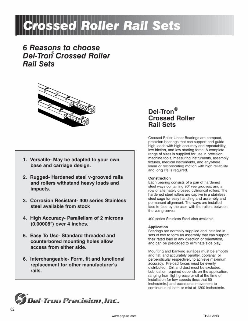
6 Reasons to chooseDel-Tron Crossed RollerRail Sets
1. Versatile- May be adapted to your ownbase and carriage design.
2. Rugged- Hardened steel v-grooved rails and rollers withstand heavy loads andimpacts.
3. Corrosion Resistant- 400 series Stainless steel available from stock
4. High Accuracy- Parallelism of 2 microns(0.00008″″) over 4 inches.
5. Easy To Use- Standard threaded and counterbored mounting holes allow access from either side.
6. Interchangeable- Form, fit and functionalreplacement for other manufacturer’s rails.
Del-TronCrossed RollerRail Sets
Crossed Roller Linear Bearings are compact,precision bearings that can support and guidehigh loads with high accuracy and repeatability,low friction, and low starting force. A completerange of sizes is supplied for use in precisionmachine tools, measuring instruments, assemblyfixtures, medical instruments, and anywhere linear or reciprocating motion with high reliabilityand long life is required.
ConstructionEach bearing consists of a pair of hardenedsteel ways containing 90° vee grooves, and arow of alternately crossed cylindrical rollers. Thehardened steel rollers are captive in a stainlesssteel cage for easy handling and assembly andpermanent alignment. The ways are installedface to face by the user, with the rollers betweenthe vee grooves.
400 series Stainless Steel also available.
ApplicationBearings are normally supplied and installed insets of two to form an assembly that can supporttheir rated load in any direction or orientation,and can be preloaded to eliminate side play.
Mounting and banking surfaces must be smoothand flat, and accurately parallel, coplanar, orperpendicular respectively to achieve maximumaccuracy. Preload forces must be evenly distributed. Dirt and dust must be excluded.Lubrication required depends on the application,ranging from light grease or oil at the time ofinstallation for low speeds (less that 50inches/min.) and occasional movement to continuous oil bath or mist at 1200 inches/min.
Crossed Roller Rail Sets
®
®
62
www.ppp-ss.com THAILAND

Ratings and SpecificationsLoad ratings in the tables are dynamic ratings for each set. Ratings are based on theoretical data, properinstallation, appropriate lubrication, and a predicted life of 10 million inches. Ratings are suggested only, basedon standard and typical industry practice, and cannot be guaranteed. Life can be increased approximately 10times by operating a given bearing at 1/2 its rated load, other factors being constant. Temperature of bearingsmust not exceed 100°C (212°F), even for short periods, since this will reduce hardness and result in significantlyreduced load capacity and working life.
Mounting holes in the way bars arethreaded, and also counterbored toalternatively permit using the next smallersize screw with threaded mounting holesin the user’s components.
ACCURACYThe accuracy of a slide is measured along it’s entire length, asillustrated in Fig 2, and expressed in terms of parallelism (Fig 1.) Actualaccuracy achieved depends on proper installation.
10
8
6
4
2
0
para
llelis
mV
.W
high grade
200 400 600 800 1000 1200
rail length L mm
63
Fig. 1
Fig. 2
μm
www.ppp-ss.com THAILAND

Crossed RollerRail Sets
B
LS
M2 M
AF
d
H
C
G
E
+00-.014" (-0.3)
D
M M2
NB-1020NB-1030NB-1040NB-1050NB-1060NB-1070NB-1080
NB-2030NB-2045NB-2060NB-2075NB-2090NB-2105NB-2120NB-2135NB-2150NB-2165NB-2180
NB-3050NB-3075NB-3100NB-3125NB-3150NB-3175NB-3200
57
1013161921
58
111316182123262932
7101417212428
0.788 (20)1.181 (30)1.575 (40)1.969 (50)2.362 (60)2.756 (70)3.150 (80)
1.181 (30)1.772 (45)2.362 (60)2.953 (75)3.544 (90)
4.134 (105)4.725 (120)5.315 (135)5.906 (150)6.496 (165)7.087 (180)
1.969 (50)2.953 (75)
3.937 (100)4.921 (125)5.906 (150)6.890 (175)7.874 (200)
0.473 (12)0.788 (20)1.063 (27)1.260 (32)1.457 (37)1.654 (42)1.969 (50)
0.709 (18)0.945 (24)1.181 (30)1.732 (44)1.969 (50)2.520 (64)2.756 (70)3.307 (84)3.544 (90)3.740 (95)
3.937 (100)
1.102 (28)1.890 (48)2.283 (58)3.071 (78)3.464 (88)
4.134 (105)4.528 (115)
2345678
23456789
101112
2345678
446188
114140167184
66105145171211237277303343382422
154220308374462528616
NB-3225NB-3250NB-3275NB-3300NB-3325NB-3350
NB-4080NB-4120NB-4160NB-4200NB-4240NB-4280NB-4320NB-4360NB-4400NB-4440NB-4480
NB-6100NB-6150NB-6200NB-6250NB-6300NB-6350NB-6400
313538424549
711151923273135394347
8121620242832
8.858 (225)9.843 (250)
10.827 (275)11.811 (300)12.795 (325)13.780 (350)
3.150 (80)4.725 (120)6.299 (160)7.874 (200)9.449 (240)
11.024 (280)12.598 (320)14.173 (360)15.748 (400)17.323 (440)18.898 (480)
3.937 (100)5.906 (150)7.874 (200)9.843 (250)
11.811 (300)13.780 (350)15.748 (400)
5.315 (135)5.709 (145)6.496 (165)6.890 (175)7.677 (195)8.071 (205)
2.283 (58)3.228 (82)
4.134 (105)5.118 (130)5.905 (175)6.890 (175)7.874 (200)8.858 (225)9.843 (250)
10.630 (270)11.614 (295)
2.165 (55)3.346 (85)
4.724 (120)5.906 (150)7.283 (185)8.465 (215)9.646 (245)
91011121314
23456789
101112
2345678
682770836924990
1,078
308484660836
1,0121,1881,3641,5401,7161,8922,068
7041,0561,4081,7602,1122,4642,816
MODELSTAINLESS
STEEL
NO. OFROLLERS IN
EACHRETAINER
LENGTHL
TRAVEL*T
NO.HOLES
RAIL SETLOAD
CAPACITYLB
MODEL
NO. OFROLLERS IN
EACHRETAINER
LENGTHL
TRAVEL*T
NO.HOLES
RAIL SETLOAD
CAPACITYLB
Please specify (SS) for Stainless Steel
*Travel is 1/2 distance from center in either direction.moment load ratings + load / life formulas. pg. 88
SSSSSSSSSSSSSS
SSSSSSSSSSSSSS
SSSSSSSSSSSSSSSSSSSSSS
64
OrderingOrder standard bearing sets from table by modelnumber according to load and travel required
Each set consists of two complete bearings (4rails, 2 roller cages, and end stops).Delivery stock to 8 weeks.
www.ppp-ss.com THAILAND

NB-1
NB-2
NB-3
NB-4
NB-6
0.335(8.5)
0.473(12)
0.708(18)
0.866(22)
1.221(31)
0.158(4.0)
0.236(6.0)
0.315(8.0)
0.433(11)
0.591(15)
0.154(3.9)
0.217(5.5)
0.327(8.3)
0.402(10.2)
0.559(14.2)
*Thread Size **Hole F clears cap screw for through mounting.
SERIES A B C
0.059(1.5)
0.079(2.0)
0.118(3.0)
0.158(4.0)
0.236(6.0)
D
NB-1
NB-2
NB-3
NB-4
NB-6
0.059 (1.5)
0.079 (2)
.118 (3)
.158 (4)
.236 (6)
0.098 (2.5)
.158 (4)
.197 (5)
.275 (7)
.334 (8.5)
.197 (5)
.316 (8)
.394 (10)
.550 (14)
.668 (17)
ROLLER SIZE ROLLER DIAMETER(D)
in (mm)
ROLLER DISTANCE(P)
in (mm)
INCREASE OFTRAVEL FOR EACHROLLER CUT-OFF
in (mm)
8.8 (4)
13.2 (6)
22 (10)
44 (20)
88 (40)
ROLLER LOADCARRYING CAP.
PER ROLLERlbs (kg)
0.059(1.5)
0.079(2.0)
0.079(2.0)
0.079(2.0)
0.118(3.0)
S
0.3937(10)
0.591(15)
0.9843(25)
1.5748(40)
1.9685(50)
0.0709(1.8)
0.0984(2.5)
0.1378(3.5)
0.1772(4.5)
0.236(6.0)
M2
M3
M4
M5
M6
#0
#2
#4
#8
#10
M E F* J**
0.065(1.65)
0.100(2.55)
0.130(3.30)
0.169(4.3)
0.205(5.2)
d
0.118(3.0)
0.173(4.4)
0.236(6.0)
0.315(8.0)
0.374(9.5)
G
0.055(1.4)
0.079(2.0)
0.122(3.1)
0.165(4.2)
0.205(5.2)
H
Profile Dimensions Mounting Dimensions
P PitchD
Modifying Length of TravelFor a given length of bearing way, since there is no slip atany load, both length of travel and load capacity depend onthe number of rollers and their pitch. The number of rollerssupplied with each standard bearing set provides a traveldistance of approximately 60% of the way length (see page56). In some cases (e.g., when mounting space is restricted)
it may be practical to increase travel at the expense of loadcapacity by removing one or more rollers instead of selectinga longer bearing. Since travel extends symmetrically aroundthe mean position, the travel increase is twice the pitch foreach roller removed. Similarly, the load capacity for the set(page 56) is reduced by twice the load capacity per roller.
65
www.ppp-ss.com THAILAND

6 Reasons to chooseDel-Tron Anti-CreepCrossed Roller Rail Sets
1. Designed for vertical applications andcantilevered loads.
2. Rugged- Hardened steel V-grooved railsand rollers withstand heavy loads.
3. Versatile- May be integrated into your owndesign.
4. High Accuracy- Parallelism of 3 microns(0.00012") over 4 inches.
5. Easy to use- Standard threaded and counterbored mounting holes allow accessfrom either side.
6. Interchangeable- Form, fit and functionalreplacement for other manufacturer's Railsets.
Anti-Creep Crossed Roller Rail Sets
®
66
Del-TronAnti-Creep CrossedRoller Rail SetsThe Anti-Creep crossed roller rail system isbased on a new concept to prevent rollercage slippage during operation. This systemallows you to mount the rail set in anyorientation while maintaining direct rollercontact to the rail surface eliminating rollercage creep. This system is ideal for verticalapplications and where high acceleration anddeceleration forces are present.
ConstructionEach bearing set contains four V-groovedRails, eight end screws, and two Anti-Creepcrossed roller retainers. The Anti-Creep crossedroller retainers utilize a studded roller anddetented rail to prevent the migration of theretainer due to vertical and cantilevered loadapplications.
ApplicationBearings are normally supplied and installed insets of two to form an assembly that can supporttheir rated load in any direction or orientation,and can be preloaded to eliminate side play.
Mounting and banking surfaces must be smoothand flat, and accurately parallel, coplanar, orperpendicular respectively to achieve maximumaccuracy. Preload forces must be evenly distributed. Dirt and dust must be excluded.Lubrication required depends on the application,ranging from light grease or oil at the time ofinstallation for low speeds (less that 50inches/min.) and occasional movement to continuous oil bath or mist at 1200 inches/min.
®
www.ppp-ss.com THAILAND

RATINGS AND SPECIFICATIONSLoad ratings in the tables are dynamic ratings for each set. Ratings are based on theoretical data, proper installation, appropriate lubrication, and apredicted life of 10 million inches. Ratings are suggested only, based on standard and typical industry practice, and cannot be guaranteed. Life canbe increased approximately 10 times by operating a given bearing at 1/2 its rated load, other factors being constant. Temperature of bearings mustnot exceed 82°C (180°F), even for short periods, since this will reduce hardness and result in significantly reduced load capacity and working life.
ACCURACYThe accuracy of a slide is measured along it’sentire length, as illustrated in Fig 2, andexpressed in terms of parallelism (Fig 1.) Actualaccuracy achieved depends on properinstallation.
Mounting holes in the way bars are threaded, andalso counterbored to alternatively permit using thenext smaller size screw with threaded mountingholes in the user’s components.
67
Fig. 1Fig. 2
INSTALLATION PROCEDURE
Note:
* Provide external mechanical stoppers.
* Set the movement to be less than the
specified stroke.
(1) Remove burrs, scratches, and dust from the rail mounting surface of the table and bed, and be careful
to prevent contamination during assembly.
(2) Apply low-viscosity oil to the contact surfaces, and align the table and the bed. (Figure 10a)
(3) Set the reference surface shown in Figure 4 onto the mounting surface with the rails assembled. Set
the table in the center position, and tighten the adjustment screws lightly so that almost no gap
remains. (Figure 10b)
(4) Keep the table in the center, tighten the rail mounting bolts lightly, loosen the end pieces of both end
faces, and remove the fastening plate. Following this, firmly retighten the end pieces.
(5) While maintaining the conditions of (4), gently move the assembly through its stroke being certain to
check that the speci.ed stroke length has been secured, and that there is no problem with the operation,
or any other irregularity.
(6) Move the table to the center and tighten only the adjustment screws on the R-retainer with the
recommended tightening torque as shown in Table 3. (Figure 10c)
(7) Gently move the table to one stroke end, and check that the table has surely come into contact with the
external mechanical stopper. Following this, tighten the adjustment screws on the R-retainer in the same
manner as (6). (Figure 10d)
(8) Move the table to the opposite stroke end, and tighten in the same manner as (6). (Figure 10e)
(9) Fasten the mounting bolts on rails 1, 2, and 3 by tightening with the recommended torque shown in
Table 4. (Figure 10f)
(10) Set the dial indicators to the center of the table and to the side (reference surface) of the table. (Figure
10g)
(11) Perform the final preload adjustment. While moving the table back and forth, repeat steps (6) and (7)
until the dial indicators show a minimum deviation.
(12) Finally, securely fasten rail 4, which has been provisionally mounted, using the recommended torque.
As with the adjustment screws, successively tighten the mounting bolts on the R-retainer while
moving the table.
www.ppp-ss.com THAILAND

NB-2-AC
NB-3-AC
NB-4-AC
NB-6-AC
0.473(12)
0.708(18)
0.866(22)
1.221(31)
0.236(6.0)
0.315(8.0)
0.433(11)
0.591(15)
0.217(5.5)
0.327(8.3)
0.402(10.2)
0.559(14.2)
*Thread Size
SERIES A B C
0.079(2.0)
0.118(3.0)
0.158(4.0)
0.236(6.0)
D
0.079(2.0)
0.079(2.0)
0.079(2.0)
0.118(3.0)
S
0.591(15)
0.9843(25)
1.5748(40)
1.9685(50)
0.0984(2.5)
0.1378(3.5)
0.1772(4.5)
0.236(6.0)
M3
M4
M5
M6
#2
#4
#8
#10
M E F* J**
0.100(2.55)
0.130(3.30)
0.169(4.3)
0.205(5.2)
d
0.173(4.4)
0.236(6.0)
0.315(8.0)
0.374(9.5)
G
0.079(2.0)
0.122(3.1)
0.165(4.2)
0.205(5.2)
H
Profile Dimensions Mounting Dimensions
Anti-Creep CrossedRoller Rail Sets
OrderingOrder standard bearing sets from table by modelnumber according to load and travel required
Each set consists of two complete bearings (4rails, 2 roller cages, and end stops).Delivery stock to 8 weeks.
NB-2030-ACNB-2045-ACNB-2060-ACNB-2075-ACNB-2090-ACNB-2105-ACNB-2120-ACNB-2135-ACNB-2150-ACNB-2165-ACNB-2180-AC
NB-3050-ACNB-3075-ACNB-3100-ACNB-3125-ACNB-3150-ACNB-3175-ACNB-3200-AC
59
151923273339414751
9131923293541
66105145171211237277303343382422
154220308374462528616
NB-3225-AC
NB-4080-ACNB-4120-ACNB-4160-ACNB-4200-ACNB-4240-ACNB-4280-AC
NB-6100-ACNB-6150-ACNB-6200-ACNB-6250-ACNB-6300-ACNB-6350-ACNB-6400-AC
43
91723293743
9151925313539
8.858 (225)
3.150 (80)4.725 (120)6.299 (160)7.874 (200)9.449 (240)
11.024 (280)
3.937 (100)5.906 (150)7.874 (200)9.843 (250)
11.811 (300)13.780 (350)15.748 (400)
5.905 (150)
2.362 (60)2.952 (75)
4.134 (105)5.118 (130)6.629 (143)6.692 (170)
2.165 (63)3.346 (85)
5.314 (135)6.220 (158)7.086 (180)9.055 (230)10.83 (275)
9
234567
2345678
682
308484660836
1,0121,188
7041,0561,4081,7602,1122,4642,816
MODEL
NO. OFROLLERS IN
EACH RETAINERLENGTH
LTRAVEL*
TNO.
HOLES
RAIL SETLOAD
CAPACITYLB MODEL
NO. OFROLLERS IN
EACH RETAINERLENGTH
LTRAVEL*
TNO.
HOLES
RAIL SETLOAD
CAPACITYLB
*Travel is 1/2 distance from center in either direction.
68**Hole F clears cap screw for through mounting.
B
LS
M2 M
AF
d
H
C
G
E
+00-.014" (-0.3)
D
M M2
moment load ratings + load / life formulas. pg. 88
23456789
101112
2345678
0.709 (18)0.984 (25)1.181 (30)1.574 (40)1.969 (50)2.559 (65)2.756 (70)3.149 (80)3.544 (90)3.740 (95)
3.937 (100)
0.984 (25)1.890 (48)2.362 (60)3.267 (83)3.543 (90)
4.055 (103)4.448 (113)
1.181 (30)1.772 (45)2.362 (60)2.953 (75)3.544 (90)4.134 (105)4.725 (120)5.315 (135)5.906 (150)6.496 (165)7.087 (180)
1.969 (50)2.953 (75)3.937 (100)4.921 (125)5.906 (150)6.890 (175)7.874 (200)
www.ppp-ss.com THAILAND

6 Reasons to chooseDel-Tron Crossed RollerSlide Tables(Aluminum)
1. High accuracy and load capacity.Precision ground V grooved waysand rollers.
2. Withstands force in any direction.Alternately crossed rollers 45° angle.
3. Easy installation. Threadedmounting holes in standard pattern.
4. 400 series Stainless steel models available. (Rails only)
5. Lightweight aluminum base andcarriage.
6. Interchangeable with othermanufacturer’s slides.
Crossed Roller Slide Tables(Aluminum)
®
69
Del-TronCrossed RollerSlide TablesOur Gold Motion Series crossed roller slidetables offer low cost and lightweight aluminum body construction to supportheavy loads with low friction and precisionlinear motion. Select from over 45 standardsizes for use in a wide range of applications - precision instruments, officeand communications equipment, surfacegrinders, tool grinders, and assembly fixtures, as examples.
Factory assembled and ready to install, eachpositioning table consists of an aluminumbase and an aluminum carriage, both precision milled, and a pair of hardened steellinear bearings. Counterbored clearanceholes, in base, permit easy mounting.Threaded holes, closely spaced in carriage,permit attaching your components withoutadditional machining. Factory preloadedbearings eliminate side play. Internal stops, inthe form of projecting screw heads betweenthe underside of the carriage and base,protect bearings from over travel during handling.
Mount on flat surfaces to provide full supportto the base. Loads stated, may be applied inany direction. Load values are calculated forweights evenly distributed on yourpositioning table. For full life of tables, werecommend careful calculation of momentsand cantilevered loads.
®
www.ppp-ss.com THAILAND

Crossed RollerSlide Tables(Aluminum)
400 series Stainless Steel Models AvailableFor applications where particulate contamination causedby corrosion must be reduced, Del-Tron offers GoldMotion crossed roller slide tables equipped withcorrosion-resistant, stainless steel, crossed roller linearbearings.
TO ORDER:Add SS to model number before “A”. For example:NBT-4085SSA
NBT-1050ANBT-1065ANBT-1080ANBT-1095ANBT-1125A
NBT-2035A-18NBT-2050ANBT-2050A-30NBT-2065ANBT-2065A-40NBT-2080A-50NBT-2080ANBT-2095A-60NBT-2095ANBT-2110A-70NBT-2125ANBT-2125A-80NBT-2155A-100NBT-2185A-120
NBT-3055ANBT-3055A-30NBT-3080A-45NBT-3105ANBT-3105A-60NBT-3130A-75NBT-3155ANBT-3155A-90NBT-3180ANBT-3180A-105NBT-3205ANBT-3205A-130NBT-3230A-155NBT-3255A-180NBT-3280A-205NBT-3305A-230
NBT-4085ANBT-4125ANBT-4165ANBT-4205ANBT-4245A
NBT-6110ANBT-6160ANBT-6260ANBT-6360A
SSSSSSSSSS
SSSSSSSSSSSSSSSSSSSSSSSSSSSS
SSSSSSSSSSSSSSSSSSSSSSSSSSSSSSSS
SSSSSSSSSS
SSSSSSSS
1.001.502.002.503.00
0.711.001.181.501.581.972.002.362.502.763.003.153.944.72
1.001.181.772.002.362.953.003.544.004.135.005.126.107.098.079.06
2.003.004.005.006.00
3.004.006.009.00
1.969 (50)2.559 (65)3.150 (80)3.740 (95)
4.921 (125)
1.378 (35)1.969 (50)1.969 (50)2.559 (65)2.559 (65)3.150 (80)3.150 (80)3.740 (95)3.740 (95)
4.331 (110)4.921 (125)4.921 (125)6.102 (155)7.283 (185)
2.165 (55)2.165 (55)3.150 (80)
4.134 (105)4.134 (105)5.118 (130)6.102 (155)6.102 (155)7.087 (180)7.087 (180)8.071 (205)8.071 (205)9.055 (230)
10.039 (255)11.024 (280)12.008 (305)
3.346 (85)4.921 (125)6.496 (165)8.071 (205)9.646 (245)
4.331 (110)6.300 (160)10.24 (260)14.17 (360)
95 (43)113 (51)144 (65)161 (73)197 (89)
66 (30)96 (44)96 (44)
114 (52)114 (52)145 (66)145 (66)162 (74)162 (74)187 (85)198 (90)198 (90)
317 (144)383 (174)
193 (88)193 (88)
220 (100)338 (154)338 (154)374 (170)477 (217)477 (217)545 (248)545 (248)576 (262)576 (262)638 (290)682 (310)748 (340)792 (360)
430 (196)600 (273)723 (329)870 (395)
1016 (462)
616 (280)1062 (483)1600 (728)2032 (924)
44888
44444888888888
4444444444888888
44444
4448
1.575 (40)2.165 (55)2.756 (70)3.346 (85)
4.528 (115)
0.984 (25)1.575 (40)1.575 (40)2.165 (55)2.165 (55)2.756 (70)2.756 (70)3.346 (85)3.346 (85)
3.937 (100)4.528 (115)4.528 (115)5.708 (145)6.889 (175)
1.378 (35)1.378 (35)2.362 (60)3.345 (85)3.345 (85)
4.330 (110)5.315 (135)5.315 (135)6.299 (160)6.299 (160)7.283 (185)7.283 (185)8.267 (210)9.251 (235)
10.236 (260)11.220 (285)
2.559 (65)4.134 (105)5.709 (145)7.283 (185)8.858 (225)
3.543 (90)5.512 (140)9.449 (240)13.39 (340)
——
1.575 (40)2.165 (55)3.346 (85)
—————
1.575 (40)1.575 (40)2.165 (55)2.165 (55)2.756 (70)3.346 (85)3.346 (85)
4.527 (115)5.708 (145)
——————————
3.346 (85)3.346 (85)
4.300 (110)5.314 (135)6.299 (160)7.283 (185)
—————
———
5.512 (140)
468
1014
2446688
10101214141822
224668
10101212141416182022
2468
10
248
12
1 x .5906 (15)2 x .5906 (15)3 x .5906 (15)4 x .5906 (15)6 x .5906 (15)
—1 x .5906 (15)1 x .5906 (15)2 x .5906 (15)2 x .5906 (15)3 x .5906 (15)3 x .5906 (15)4 x .5906 (15)4 x .5906 (15)5 x .5906 (15)6 x .5906 (15)6 x .5906 (15)8 x .5906 (15)
10 x .5906 (15)
——
1 x .9843 (25)2 x .9843 (25)2 x .9843 (25)3 x .9843 (25)4 x .9843 (25)4 x .9843 (25)5 x .9843 (25)5 x .9843 (25)6 x .9843 (25)6 x .9843 (25)7 x .9843 (25)8 x .9843 (25)9 x .9843 (25)
10 x .9843 (25)
—1 x 1.575 (40)2 x 1.575 (40)3 x 1.575 (40)4 x 1.575 (40)
—1 x 1.969 (50)3 x 1.969 (50)5 x 1.969 (50)
MODELSTAINLESS
STEELTRAVEL*
TLENGTH
L
LOADCAPACITYLBF (kgf)
NO.HOLES
SPACINGU W
BASE MOUNTING HOLES(COUNTERBORED)
NO.HOLES
SPACINGM
CARRIAGEMOUNTING HOLES
(THREADED)
*Travel is 1/2 distance from center in either direction.moment load ratings + load / life formulas. pg. 88
70
www.ppp-ss.com THAILAND

Specifications:
Straight Line Accuracy0.0001″/inch of travel
Positional Repeatability0.0001″
Coefficient of Friction0.003 typical
ConstructionAluminum carriage and base,hardened steel crossed roller rail sets.400 Series SS Rail Sets available.
FinishCarriage: Gold anodize, Base: Blackanodize
OrderingOrder standard slide tables from tableby model number according to loadand travel required.
Delivery stock to 6 weeks.
NBT-1000A
NBT-2000A
NBT-3000A
NBT-4000A
NBT-6000A
0.590(15)
0.827(21)
1.102(28)
1.378(35)
1.772(45)
1.181(30)
1.575(40)
2.362(60)
3.150(80)
3.937(100)
0.160(4.1)
0.256(6.5)
0.354(9)
0.413(10.5)
0.512(13)
Dimensions in inches (mm)
SERIES
HEIGHTA
±.005 (0.13)
WIDTHB
±.010 (0.25)
BASETHICKNESS
C
Profile Dimensions
T2 L
CA
B
NBT-1000A
NBT-2000A
NBT-3000A
NBT-4000A
NBT-6000A
0.689(17.5)
0.689(17.5)
1.083(27.5)
1.673(42.5)
2.165(55)
0.394(10)
0.591(15)
0.984(25)
1.575(40)
1.969(50)
4-40
6-32
10-32
10-32
1/4-20
0.177(4.5)
0.315(8)
0.413(10.5)
0.512(13)
0.630(16)
0.197(5)
0.197(5)
0.394(10)
0.394(10)
0.394(10)
0.866(22)
1.181(30)
1.575(40)
2.165(55)
2.362(60)
0.198(5)
0.241(6.1)
0.328(8.3)
0.328(8.3)
0.406(10.3)
0.125(3.1)
0.149(3.7)
0.197(5)
0.197(5)
0.266(6.7)
.125(3.2).145(3.7).205(5.2).205(5.2).315(8.0)
SERIES N P J K R S D d hSPACING THREAD DEPTH SPACING COUNTERBORE
CARRIAGE BASE
Dimensions in inches (mm)
Mounting Dimensions
CARRIAGE MOUNTING DIMENSIONS
K
P
J
N M
BASE MOUNTING DIMENSIONS
S
D
W
d
UR
71
h
www.ppp-ss.com THAILAND

6 Reasons to chooseDel-Tron Anti-CreepCrossedRoller Slide Tables(Aluminum)
1. Anti-Creep Crossed Roller Technology.Ideal for vertical and cantilevered loadapplications.
2. High accuracy and load capacity.Precision V grooved rails and rollers.
3. Lightweight aluminum carriage and basedesign.
4. Withstands force in any direction.Alternately crossed roller cage design.
5. Easy installation. Threaded andcounterbored mounting holes in standard pattern.
6. Interchangeable with other manufacturer'sslides.
Del-TronAnti-Creep CrossedRoller Slide TablesThe Anti-Creep crossed roller slide tablesutilize our Anti-Creep crossed roller railsystems to prevent roller cage slippageduring operation. This system allows youto mount the table in any orientation whilemaintaining direct roller contact to the railsurface eliminating roller cage creep.These tables are ideal for verticalapplications and where high accelerationand deceleration forces are present.
Factory assembled and ready to install, eachpositioning table consists of an aluminumbase and an aluminum carriage, both precision milled, and a pair of hardened steellinear bearings. Counterbored clearanceholes, in base, permit easy mounting.Threaded holes, closely spaced in carriage,permit attaching your components withoutadditional machining. Factory preloadedbearings eliminate side play. Internal stops, inthe form of projecting screw heads betweenthe underside of the carriage and base,protect bearings from over travel during handling.
Mount on flat surfaces to provide full supportto the base. Loads stated, may be applied inany direction. Load values are calculated forweights evenly distributed on yourpositioning table. For full life of tables, werecommend careful calculation of momentsand cantilevered loads.
Anti-Creep Crossed Roller SlideTables (Aluminum)
®
®
72
www.ppp-ss.com THAILAND

Anti-Creep CrossedRoller Slide Tables(Aluminum)
NBT-1050A-ACNBT-1065A-ACNBT-1080A-ACNBT-1095A-ACNBT-1125A-AC
NBT-2035A-18-ACNBT-2050A-ACNBT-2065A-ACNBT-2080A-ACNBT-2095A-ACNBT-2110A-70-ACNBT-2125A-ACNBT-2155A-100-ACNBT-2185A-120-AC
NBT-3055A-ACNBT-3080A-45-ACNBT-3105A-ACNBT-3130A-75-ACNBT-3155A-ACNBT-3180A-ACNBT-3205A-ACNBT-3230A-155-AC
NBT-4085A-ACNBT-4125A-ACNBT-4165A-ACNBT-4205A-ACNBT-4245A-AC
NBT-6110A-ACNBT-6160A-ACNBT-6260A-ACNBT-6360A-AC
0.98 (25)1.18 (30)1.57 (40)1.96 (50)2.75 (70)
0.71 (18)0.98 (25)1.18 (30)1.57 (40)1.96 (50)2.56 (65)2.75 (70)3.54 (90)
3.93 (100)
0.98 (25)1.89 (48)2.36 (60)3.27 (83)3.54 (90)
4.05 (103)4.45 (113)5.90 (150)
2.36 (60)2.95 (75)
4.13 (105)5.12 (130)5.63 (143)
2.48 (63)3.35 (85)
6.22 (158)9.06 (230)
1.969 (50)2.559 (65)3.150 (80)3.740 (95)4.921 (125)
1.378 (35)1.969 (50)2.559 (65)3.150 (80)3.740 (95)
4.331 (110)4.921 (125)6.102 (155)7.283 (185)
2.165 (55)3.150 (80)
4.134 (105)5.118 (130)6.102 (155)7.087 (180)8.071 (205)9.055 (230)
3.346 (85)4.921 (125)6.496 (165)8.071 (205)9.646 (245)
4.331 (110)6.300 (160)10.24 (260)14.17 (360)
95 (43)113 (51)144 (65)161 (73)197 (89)
66 (30)96 (44)
114 (52)145 (66)162 (74)187 (85)198 (90)
317 (144)383 (174)
193 (88)220 (100)338 (154)374 (170)477 (217)545 (248)576 (262)638 (290)
430 (196)600 (273)723 (329)870 (395)
1016 (462)
616 (280)1062 (483)1600 (728)2032 (924)
44888
444888888
44444488
44444
4448
1.575 (40)2.165 (55)2.756 (70)3.346 (85)
4.528 (115)
0.984 (25)1.575 (40)2.165 (55)2.756 (70)3.346 (85)
3.937 (100)4.528 (115)5.708 (145)6.889 (175)
1.378 (35)2.362 (60)3.345 (85)
4.330 (110)5.315 (135)6.299 (160)7.283 (185)8.267 (210)
2.559 (65)4.134 (105)5.709 (145)7.283 (185)8.858 (225)
3.543 (90)5.512 (140)9.449 (240)13.39 (340)
——
1.575 (40)2.165 (55)3.346 (85)
———
1.575 (40)2.165 (55)2.756 (70)3.346 (85)
4.527 (115)5.708 (145)
——————
3.346 (85)4.300 (110)
—————
———
5.512 (140)
468
1014
2468
1012141822
2468
10121416
2468
10
248
12
1 x .5906 (15)2 x .5906 (15)3 x .5906 (15)4 x .5906 (15)6 x .5906 (15)
—1 x .5906 (15)2 x .5906 (15)3 x .5906 (15)4 x .5906 (15)5 x .5906 (15)6 x .5906 (15)8 x .5906 (15)
10 x .5906 (15)
—1 x .9843 (25)2 x .9843 (25)3 x .9843 (25)4 x .9843 (25)5 x .9843 (25)6 x .9843 (25)7 x .9843 (25)
—1 x 1.575 (40)2 x 1.575 (40)3 x 1.575 (40)4 x 1.575 (40)
—1 x 1.969 (50)3 x 1.969 (50)5 x 1.969 (50)
MODELTRAVEL*T (mm)
LENGTHL
LOADCAPACITYLBF (kgf)
NO.HOLES
SPACINGU W
BASE MOUNTING HOLES(COUNTERBORED)
NO.HOLES
SPACINGM
CARRIAGEMOUNTING HOLES
(THREADED)
*Travel is 1/2 distance from center in either direction.moment load ratings + load / life formulas. pg.88
73
www.ppp-ss.com THAILAND

Specifications:
Straight Line Accuracy0.0001″/inch of travel
Positional Repeatability0.0001″
Coefficient of Friction0.003 typical
ConstructionAluminum carriage and base,hardened steel crossed roller rail sets.
FinishCarriage: Gold anodize, Base: Blackanodize
OrderingOrder standard slide tables from tableby model number according to loadand travel required.
Delivery stock to 6 weeks.
NBT-1000A-AC
NBT-2000A-AC
NBT-3000A-AC
NBT-4000A-AC
NBT-6000A-AC
0.590(15)
0.827(21)
1.102(28)
1.378(35)
1.772(45)
1.181(30)
1.575(40)
2.362(60)
3.150(80)
3.937(100)
0.160(4.1)
0.256(6.5)
0.354(9)
0.413(10.5)
0.512(13)
Dimensions in inches (mm)
SERIES
HEIGHTA
±.005 (0.13)
WIDTHB
±.010 (0.25)
BASETHICKNESS
C
Profile Dimensions
T2 L
CA
B
NBT-1000A-AC
NBT-2000A-AC
NBT-3000A-AC
NBT-4000A-AC
NBT-6000A-AC
0.689(17.5)
0.689(17.5)
1.083(27.5)
1.673(42.5)
2.165(55)
0.394(10)
0.591(15)
0.984(25)
1.575(40)
1.969(50)
4-40
6-32
10-32
10-32
1/4-20
0.177(4.5)
0.315(8)
0.413(10.5)
0.512(13)
0.630(16)
0.197(5)
0.197(5)
0.394(10)
0.394(10)
0.394(10)
0.866(22)
1.181(30)
1.575(40)
2.165(55)
2.362(60)
0.198(5)
0.241(6.1)
0.328(8.3)
0.328(8.3)
0.406(10.3)
0.125(3.1)
0.149(3.7)
0.197(5)
0.197(5)
0.266(6.7)
.125(3.2).145(3.7).205(5.2).205(5.2).315(8.0)
SERIES N P J K R S D d hSPACING THREAD DEPTH SPACING COUNTERBORE
CARRIAGE BASE
Dimensions in inches (mm)
Mounting Dimensions
CARRIAGE MOUNTING DIMENSIONS
K
P
J
N M
BASE MOUNTING DIMENSIONS
S
D
W
d
UR
74
h
www.ppp-ss.com THAILAND

Inch Series Crossed Roller Slide TablesNBTA Type
NBTA-221NBTA-232NBTA-243NBTA-254NBTA-265NBTA-276NBTA-287NBTA-298NBTA-2109NBTA-21110NBTA-21211
NBTA-332NBTA-343NBTA-354NBTA-365NBTA-376NBTA-387NBTA-398NBTA-3109NBTA-31110NBTA-31211
NBTA-443NBTA-465NBTA-487NBTA-4109NBTA-41211NBTA-41413NBTA-41615
SSSSSSSSSSSSSSSSSSSSSS
SSSSSSSSSSSSSSSSSSSS
SSSSSSSSSSSSSS
123456789
1011
23456789
1011
3579
111315
23456789
101112
3456789
101112
468
10121416
154 (70)198 (90)264 (120)308 (140)374 (170)418 (190)462 (210)528 (240)572 (259)638 (289)682 (309)
198 (90)264 (120)308 (140)374 (170)418 (190)462 (210)528 (240)572 (259)638 (289)682 (309)
528 (240)792 (359)
1056 (479)1320 (599)1584 (719)1848 (838)2024 (918)
44444488888
4444488888
4488888
1.0002.0003.0004.0005.0006.0007.0008.0009.000
10.00011.000
2.0003.0004.0005.0006.0007.0008.0009.000
10.00011.000
3.0005.0007.0009.000
11.00013.00015.000
5.0006.0007.0008.0009.000
5.0006.0007.0008.0009.000
5.0007.0009.000
11.00013.000
2468
10121416182022
468
10121416182022
6101418222630
Centered1 x 1.000 2 x 1.0003 x 1.0004 x 1.0005 x 1.000 6 x 1.0007 x 1.0008 x 1.000 9 x 1.000
10 x 1.000
1 x 1.0002 x 1.0003 x 1.0004 x 1.000 5 x 1.0006 x 1.0007 x 1.000 8 x 1.0009 x 1.000
10 x 1.000
2 x 1.000 4 x 1.000 6 x 1.0008 x 1.000
10 x 1.00012 x 1.00014 x 1.000
MODELSTAINLESS
STEELTRAVEL*
TLENGTH
L
LOADCAPACITYLBF (kgf)
NO.HOLES
SPACINGU W
BASE MOUNTING HOLES(COUNTERBORED)
NO.HOLES
SPACINGM
CARRIAGEMOUNTING HOLES
(THREADED)
This series of crossed roller tables offers the designerrobust slide tables made to the same standards as ourNBTA series but with inch type overall dimensions. Eachcross section is designated by its width 2″, 3″, and 4″. Thisseries is interchangeable with those of other manufacturer’stables and is available from stock at competitive prices.
400 series Stainless Steel Models AvailableFor applications where particulate contaminationcaused by corrosion must be reduced, Del-Tron offerscrossed roller slide tables equipped with corrosion-resistant, stainless steel, crossed roller linear bearings.
Base & carriage: aluminumRails, rollers, retainers & fasteners: stainless steel
TO ORDER:Add SS to model number. For example: NBTA-221SS
*Travel is 1/2 distance from center in either direction.moment load ratings + load / life formulas. pg. 88
75
www.ppp-ss.com THAILAND

Specifications:
Straight Line Accuracy0.0001″/inch of travel
Positional Repeatability0.0001″
Coefficient of Friction0.003 typical
ConstructionAluminum carriage and base, hardened steelcrossed roller rail sets. 400 series stainlesssteel available.
FinishCarriage: Clear anodize, Base: Clear anodize
OrderingOrder standard slide tables from table bymodel number according to load and travelrequired.
Delivery stock to 6 weeks.
T2 L
CA
B
NBTA-2
NBTA-3
NBTA-4
.980
1.250
1.440
2.000
3.000
4.000
.205
.405
.445
SERIES
HEIGHTA
±.005
WIDTHB
±.010
BASETHICKNESS
C
Profile Dimensions
NBTA-2
NBTA-3
NBTA-4
1.005
1.005
1.005
0.875
1.375
1.875
#8-32
#10-32
1/4-20
0.330
0.330
0.327
0.496
0.496
0.496
1.500
2.375
3.375
0.275
0.330
0.406
0.185
0.204
0.281
.170
.205
.312
#8
#10
#1/4
SERIES N P J K R S D d h SizeSPACING THREAD DEPTH SPACING COUNTERBORE Screw
CARRIAGE BASEMounting Dimensions
CARRIAGE MOUNTING DIMENSIONS
K
P
J
N M
BASE MOUNTING DIMENSIONS
S
D
W
d
UR
76
h
www.ppp-ss.com THAILAND

6 Reasons to chooseDel-Tron® Crossed RollerSlide Tables(Steel)
1. High Accuracy - .00008″″ parallelism.
2. High Load Capacity - Crossed roller wayconstruction handles loads up to 2,640 lb.
3. Interchangeable with other manufacturer’stables.
4. Low Friction - 0.003 coefficient of frictionfor smooth operation.
5. Standard Mounting - Holes provided.
6. Backlash Free - Factory preloaded forminimum axial play.
Crossed Roller Slide Tables
Crossed Roller Slide Tables are factory assembled, and ready to install. They useDel-Tron crossed roller bearings to provide veryprecise linear motion with low friction and highsupport stiffness for the load. A selection ofmore than 40 standard sizes is available forapplications including precision instruments,office and communications equipment, surfacegrinders, tool grinders, assembly fixtures, andanywhere precise linear positioning is required.
ConstructionEach slide table consists of a one piece base, aone piece carriage, and a pair of linear bearings.The bearings are factory preloaded to eliminateside play.
Counterbored clearance holes in the base permit easy mounting in your structure.Threaded holes in the carriage are closelyspaced to permit attaching your componentswithout additional machining in most cases.
Standard material for base and carriage is coldrolled steel, with black oxide finish.
ApplicationMount on a flat surface to provide full support tothe base.
Although it is seldom needed, the carriage surface can be machined or additional mountingholes can be added if the following precautionsare observed:
1. Do not disassemble the table since reassembly and readjustment of the preloading require special procedures.
2. Protect the ways against entry of chips anddebris.
3. Drill only blind holes through the carriage toavoid depositing chips inside the unit.
4. Avoid intersection with internal mounting orpreloading screws.
5. Avoid clamping forces in excess of the ratedload capacity.
Internal stops, in the form of projecting screwheads between the under side of the carriageand the base, are intended only to protect thebearings from over travel during handling.Provide separate stops appropriate for your loadif needed.
The ends of the carriage contain tapped holesthat permit easy attachment of way covers, bellows, or other shields to exclude dust andkeep the ways clean.
Crossed Roller Slide Tables(Steel)
®
77
www.ppp-ss.com THAILAND

Crossed RollerSlide Tables(Steel)
NBT-1025NBT-1035NBT-1045NBT-1055NBT-1065NBT-1075NBT-1085
NBT-2035NBT-2050NBT-2065NBT-2080NBT-2095NBT-2110NBT-2125NBT-2140NBT-2155NBT-2170NBT-2185
NBT-3055NBT-3080NBT-3105NBT-3130NBT-3155NBT-3180NBT-3205NBT-3230NBT-3255NBT-3280NBT-3305
NBT-4085NBT-4125NBT-4165NBT-4205NBT-4245NBT-4285NBT-4325
NBT-6110NBT-6160NBT-6210NBT-6260NBT-6310
0.472 (12)0.709 (18)0.984 (25)1.260 (32)1.575 (40)1.772 (45)1.969 (50)
0.709 (18)1.181 (30)1.575 (40)1.969 (50)2.362 (60)2.756 (70)3.150 (80)3.543 (90)
3.937 (100)4.331 (110)4.724 (120)
1.181 (30)1.772 (45)2.362 (60)2.953 (75)3.543 (90)
4.134 (105)5.118 (130)6.102 (155)7.087 (180)8.071 (205)9.055 (230)
1.969 (50)2.953 (75)
4.134 (105)5.118 (130)6.102 (155)7.283 (185)8.268 (210)
2.362 (60)3.740 (95)
5.118 (130)6.496 (165)7.874 (200)
0.984 (25)1.378 (35)1.772 (45)2.165 (55)2.559 (65)2.953 (75)3.346 (85)
1.378 (35)1.969 (50)2.559 (65)3.150 (80)3.740 (95)
4.331 (110)4.921 (125)5.512 (140)6.102 (155)6.693 (170)7.283 (185)
2.165 (55)3.150 (80)
4.134 (105)5.118 (130)6.102 (155)7.087 (180)8.071 (205)9.055 (230)10.04 (255)11.02 (280)12.01 (305)
3.346 (85)4.921 (125)6.496 (165)8.071 (205)9.646 (245)11.22 (285)12.80 (325)
4.331 (110)6.300 (160)8.268 (210)10.24 (260)12.20 (310)
26 (12)35 (16)44 (20)57 (26)70 (32)79 (36)88 (40)
88 (40)137 (63)165 (75)209 (95)
231 (105)264 (120)286 (130)319 (145)341 (155)374 (170)396 (180)
277 (126)405 (184)484 (220)605 (275)682 (310)781 (355)825 (375)924 (420)990 (450)
1078 (490)1144 (520)
616 (280)858 (390)
1034 (470)1243 (565)1452 (660)1639 (745)1826 (830)
880 (400)1518 (690)1914 (870)
2288 (1040)2640 (1200)
4448888
4448888
12121216
444466
1010101212
44466
1010
44666
0.709 (18)1.102 (28)1.496 (38)1.890 (48)2.283 (58)2.677 (68)3.071 (78)
0.984 (25)1.575 (40)2.165 (55)2.756 (70)3.346 (85)
3.937 (100)4.528 (115)5.118 (130)5.709 (145)6.299 (160)6.890 (175)
1.378 (35)2.362 (60)3.345 (85)
4.331 (110)5.315 (135)6.266 (160)7.283 (185)8.268 (210)9.252 (235)10.24 (260)11.22 (285)
2.559 (65)4.134 (105)5.709 (145)7.283 (185)8.858 (225)10.43 (265)12.01 (305)
3.543 (90)5.512 (140)7.480 (190)9.449 (240)11.42 (290)
———————
———————————
————
3.346 (85)4.331 (110)5.315 (135)6.299 (160)7.283 (185)8.268 (210)9.252 (235)
———
4.134 (105)5.709 (145)7.283 (185)10.04 (225)
——
3.543 (90)5.512 (140)7.480 (190)
———
1.102 (28)1.496 (38)1.890 (48)2.283 (58)
———
1.575 (40)2.165 (55)2.756 (70)3.346 (85)
3.937 (100)4.528 (115)5.118 (130)5.709 (145)
——————
3.346 (85)4.331 (110)5.315 (135)6.299 (160)7.283 (185)
—————
4.134 (105)5.709 (145)
—————
———————
———————————
—————————
4.331 (110)5.315 (135)
———————
—————
———————
———————
2.756 (70)3.346 (85)
3.937 (100)4.528 (115)
———————————
———————
—————
2468
101214
2468
10121416182022
2468
10121416182022
2468
101214
2468
10
—1 × .3937 (10)2 × .3937 (10)3 × .3937 (10)4 × .3937 (10)5 × .3937 (10)6 × .3937 (10)
—1 × .5906 (15)2 × .5906 (15)3 × .5906 (15)4 × .5906 (15)5 × .5906 (15)6 × .5906 (15)7 × .5906 (15)8 × .5906 (15)9 × .5906 (15)
10 × .5906 (15)
—1 × .9843 (25)2 × .9843 (25)3 × .9843 (25)4 × .9843 (25)5 × .9843 (25)6 × .9843 (25)7 × .9843 (25)8 × .9843 (25)9 × .9843 (25)
10 × .9843 (25)
—1 × 1.575 (40)2 × 1.575 (40)3 × 1.575 (40)4 × 1.575 (40)5 × 1.575 (40)6 × 1.575 (40)
—1 × 1.969 (50)2 × 1.969 (50)3 × 1.969 (50)4 × 1.969 (50)
MODELTRAVEL*
TLENGTH
L
LOADCAPACITYLBF (kgf)
NO.HOLES U V W X Y
NO.HOLES
SPACINGM
CARRIAGEMOUNTING HOLES
(THREADED)BASE MOUNTING HOLES(COUNTERBORED) SPACING
T2 L
O
*Travel is 1/2 distance from center in either direction.
moment load ratings + load / life formulas. pg. 88
78
www.ppp-ss.com THAILAND

Crossed Roller Slide Tables(steel)
AccuracyTop and bottom mounting surfaces andcarriage side surfaces are ground flat andparallel to the line of motion. Accuracy ofmovement (V) is measured as a deflection overthe center line of the carriage as shown.Accuracies, measured without load, dependprimarily on overall length as listed.Deflections (H) measured at either side of thecarriage under the same conditions.
OrderingOrder standard positioning tables from table bymodel number according to load and travelrequired.
Delivery stock to 6 weeks.
V
H
NBT-1025NBT-1035NBT-1045NBT-1055NBT-1065NBT-1075NBT-1085
NBT-2035NBT-2050NBT-2065NBT-2080NBT-2095NBT-2110NBT-2125NBT-2140NBT-2155NBT-2170NBT-2185
NBT-3055NBT-3080NBT-3105NBT-3130NBT-3155NBT-3180NBT-3205NBT-3230NBT-3255NBT-3280NBT-3305
NBT-4085NBT-4125NBT-4165NBT-4205NBT-4245NBT-4285NBT-4325
NBT-6110NBT-6160NBT-6210NBT-6260NBT-6310
0.000080.000080.000080.000080.000080.000080.00008
0.000080.000080.000080.000080.000080.000120.000120.000120.000120.000120.00012
0.000080.000080.000120.000120.000120.000120.000120.000120.000120.000120.00012
0.000080.000120.000120.000120.000120.000120.00016
0.000120.000120.000120.000120.00012
0.000160.000160.000160.000200.000200.000200.00020
0.000160.000160.000200.000200.000200.000240.000240.000240.000240.000280.00028
0.000080.000080.000200.000200.000240.000240.000280.000280.000280.000280.00028
0.000200.000240.000280.000280.000280.000280.00031
0.000240.000240.000280.000280.00028
(2)(2)(2)(2)(2)(2)(2)
(2)(2)(2)(2)(2)(3)(3)(3)(3)(3)(3)
(2)(2)(3)(3)(3)(3)(3)(3)(3)(3)(3)
(2)(3)(3)(3)(3)(3)(4)
(3)(3)(3)(3)(3)
(4)(4)(4)(5)(5)(5)(5)
(4)(4)(5)(5)(5)(6)(6)(6)(6)(7)(7)
(5)(5)(6)(6)(6)(7)(7)(7)(7)(7)(7)
(5)(6)(7)(7)(7)(7)(8)
(6)(6)(7)(7)(7)
PART # VERTICAL HORIZONTAL
ACCURACY
79
Dim. in inches (μm)
www.ppp-ss.com THAILAND

Crossed Roller Slide Tables (Steel)
Load RatingsSee “Ratings andSpecifications” page 90
The load capacities stated inthe tables may be applied inany direction, and areassumed to be centered andevenly distributed over thetable. Calculate moments andcantilevered loads carefullysince inadvertent overloadingwill reduce service life.
NBT-1000
NBT-2000
NBT-3000
NBT-4000
NBT-6000
0.492(12.5)
0.689(17.5)
1.083(27.5)
1.673(42.5)
2.165(55)
0.394(10)
0.591(15)
0.984(25)
1.575(40)
1.969(50)
M2
M3
M4
M5
M6
.236(6)
.276(7)
.374(9.5)
0.512(13)
.551(14)
0.138(3.5)
0.197(5)
0.394(10)
0.394(10)
0.394(10)
0.866(22)
1.181(30)
1.575(40)
2.165(55)
2.362(60)
0.161(4.5)
0.236(6.5)
0.295(8)
0.374(10)
0.433(11.5)
0.100(2.55)
0.138(3.5)
0.177(4.5)
0.217(5.5)
0.276(7)
.100(2.5)
.138(3.5)
.177(4.5)
.213(5.4)
.276(7.0)
Mounting Dimensions
SERIES N P J K R S D d h
SPACING THREAD DEPTH SPACING C’BORE DEPTH
CARRIAGE BASE
Dimensions in inches (mm)
CARRIAGE MOUNTING DIMENSIONS
BASE MOUNTING DIRECTIONS
K
P
J
N M
S
D
W
d
UR
Y
VX
NBT-1000
NBT-2000
NBT-3000
NBT-4000
NBT-6000
0.669(17)
0.827(21)
1.102(28)
1.378(35)
1.772(45)
1.181(30)
1.575(40)
2.362(60)
3.150(80)
3.937(100)
0.217(5.5)
0.256(6.5)
0.354(9)
0.413(10.5)
0.512(13)
0.098(2.5)
0.134(3.4)
0.217(5.5)
0.256(6.5)
0.315(8)
—
—
—
—
0.591(15)
0.472(12)
0.630(16)
1.575(40)
2.165(55)
2.362(60)
—
—
—
—
3.622(92)
M2
M2
M3
M3
M4
Dimensions in inches (mm)
Profile Dimensions
SERIES * HEIGHTA
±.004 (0.1)
WIDTHB**
±.004 (0.1)
FLANGEHEIGHT
O C E F G H
DUST COVER ATTACHMENTHOLES
THREAD
* Series NBT-1000 Tables use series NB-1 bearings etc. ** Except Series NBT-1000 and NBT-2000 +.008 (+0.2)–.016 (–0.4)
80
B
G
F
E
O
C
A
H
h
www.ppp-ss.com THAILAND

RecirculatingBall SlideGuides(BSG)
The BSG type consists of a block and aguide rail, both having two R-shape raceway grooves machined by precisiongrinding. The block consists of a mainbody having raceway grooves and a resinreturn cap ensuring smooth circulation ofballs. These precision steel balls roll in therespective raceway groove with contact atfour points.
• Smooth and Stable operation. Since precision steel balls are used as rolling elements, the rolling resistance is extremely small, ensuring smooth and stable operation.
• Compact, lightweight, and low price. Theblock is a simple structure, so the slideguide is compact and inexpensive. Its compactness and light weight also makethis product optimum for linear operation athigh speed.
• High load capacity utilizing the R-shapedgroove. The raceway surface over whichthe balls roll is an R-shaped groove, offering a large contact area. Therefore, theproduct features a large load capacity anda long effective life.
• Four-point contact to carry load andmoment in all directions. The Gothic archgroove, where the balls contact the raceway surface at four points, enables theload and moment to be carried in all directions.
• 400 series Stainless steel type (BSGS) isavailable. The BSGS type uses stainlesssteel for the block, ball bearing and guiderail, thus having superior corrosionresistance.
• Extra wide type (BSGW) is also available.With its increased number of rolling elements and increased width, this unit canreplace the use of two linear guides.Stiffness in regard to moment load isincreased, thus creating an effective compact linear motion mechanism.
• Slide guides are supplied with temporaryends stops. They are not to be used as positive stops.
6 Reasons to chooseDel-Tron RecirculatingBall Slide Guides(BSG)
1. Smooth and stable operation.
2. Compact, lightweight and low price.
3. High load capacity due to R-shapedgroove.
4. Four-point contact to carry load andmoment in all directions.
5. 400 Series Stainless steel type available.
6. Extra wide type available.
Recirculating Ball Slide Guides (BSG)
81
www.ppp-ss.com THAILAND

NomenclaturePart number for BSG
BSG S 5 UU 2
•Type
S Stainless Steel
•Height of guide
None Without sealUU Seals on both sides
•Seal
• Material
AccuracyHeight (H) tolerance ±.0016 (±0.040)Difference of heights (H) between paired ones .0006 (0.015)Width (W1) tolerance ±.0016 (±0.040)
Difference of widths (W1) between paired ones .0008 (0.020)
Running parallelism of C plane with respect to A plane See Fig. 2Running parallelism of D plane with respect to B plane See Fig. 2
BSG Type
160 N
• Number of carriages per rail
• Length of guide rail (mm)
• Rail mounting hole
The corners of the reference planes should be finished with undercuts as shown in Figure 3. Therecommended heights of the shoulders of the mounting planes are as shown in the table. To attain highaccuracy, it is recommended to finish the mounting planes of the bed and table to an accuracy the same asor better than that of the guide rail and block.
MountingRequirements
Recommended Tightening Torques: Therecommended tightening torques for the mountingbolts (hex socket head bolts) are shown here.
Nominal Bolt Size Tightening Torques
M2
M3
M4
M5
.295 (4)
.738 (1.0)
1.884 (2.5)
3.614(4.9)
Fixing Method
To install a BSG Slide Guide (Fig. 4), confirm the reference planes as shown in Figure 1, then let thereference planes of the bed and table make close contact with the reference planes of the object andfix them. When using two guide rails, fix the reference side in a state in which it is closely contactedwith the reference plane. Fix the adjustment side after adjusting the traveling state with either the guiderails or the block in a free state.
Unit: inches (mm)
Unit: inches (mm)
Unit:lb-ft (N·M)
TravelAccuracy
Fig. 2
C
A
D
B
W1
H
h 1
h 2
Ref
eren
ceP
lane
s
Fig. 3
Fig. 4
Fig. 1
marking
None CounterboreN Threaded hole
BSGS5 Only
part number h1 h2
BSGS5
BSGS8
BSG 10
BSG13
BGG16
BSG25
BSGS9W
BSG12W
BGG14W
BSG16W
.079 (2)
.098 (2.5)
.118 (3)
.157 (4)
.197 (5)
.197 (5)
.118 (3)
.118 (3)
.157 (4)
.197 (5)
.039 (1)
.039 (1)
.059 (1.5)
.079 (2)
.138 (3.5)
.197 (5)
.059 (1.5)
.098 (2.5)
.098 (2.5)
.098 (2.5)
Mounting Surface Dimensions
82
www.ppp-ss.com THAILAND

LM x P
P
LM x P
P
L (Lmm)
BSG10BSG10UU
BSG13BSG13UU
BSG16BSG16UU
BSG25BSG25UU
BSGS5BSGS5UU
BSGS8BSGS8UU
BSGS10BSGS10UU
BSGS13BSGS13UU
BSGS16BSGS16UU
BSGS25BSGS25UU
MODEL
2.165 (55) [4]6.299 (160) [11]
2.165 (55) [4]5.118 (130) [9]
2.953 (75) [4]7.677 (195) [10]
6.693 (170) [7]14.567 (370) [15]
9.055 (230) [6]26.378 (670) [17]
11.024 (280) [5]34.646 (880) [15]
2.756 (70) [5]
2.756 (70) [5]
3.740 (95) [5]10.827 (275) [14]
8.661 (220) [9]18.504 (470) [19]
12.205 (310) [8]
13.386 (340) [6]
3.937 (100) [7]
3.346 (85) [6]
4.527 (115) [6]
10.630 (270) [11]
16.929 (430) [11]
18.110 (460) [8]
[M] L (Lmm) [M] L (Lmm) [M] L (Lmm) [M]
GUIDE RAIL LENGTHS / [NUMBER OF HOLES]
MODEL
BSG12WBSG12WUU
BSG14WBSG14WUU
BSG16WBSG16WUU
BSGS9WBSGS9WUU
BSGS12WBSGS12WUU
BSGS14WBSGS14WUU
BSGS16WBSGS16WUU
3.150 (80) [3]7.874 (200) [7]
3.150 (80) [3]7.874 (200) [7]
4.331 (110) [3]12.205 (310) [8]
5.906 (150) [4]21.654 (550) [14]
4.331 (110) [4]9.055 (230) [8]
4.331 (110) [4]9.055 (230) [8]
5.906 (150) [4]15.354 (390) [10]
9.055 (230) [6]26.378 (670) [17]
5.512 (140) [5]10.236 (260) [9]
5.512 (140) [5]10.236 (260) [9]
7.480 (190) [5]18.504 (470) [12]
12.205 (310) [8]
6.693 (170) [6]11.417 (290) [10]
6.693 (170) [6]11.417 (290) [10]
9.055 (230) [6]
16.929 (430) [11 ]
L (Lmm) [M] L (Lmm) [M] L (Lmm) [M] L (Lmm) [M]
GUIDE RAIL LENGTHS / [NUMBER OF HOLES]
Ball Slide GuideBSGBSGS (400 series Stainless Steel)
Ball Slide GuideExtra WideBSG-W BSGS-W (400 series
Stainless Steel)
.591(15)
.591(15)
.788(20)
.984(25)
1.575(40)
2.362(60)
1.181(30)
1.181(30)
1.575(40)
1.575(40)
P
P
MAX LENGTH
STEEL STAINLESS
N/A
N/A
19.7(500)
19.7(500)
74.8(1900)
74.8(1900)
13.4(340)
27.6(700)
39.37(1000)
39.37(1000)
39.37(1000)
39.37(1000)
MAX LENGTH
STEEL STAINLESS
N/A
39.37(1000)
74.8(1900)
74.8(1900)
27.6(700)
39.37(1000)
39.37(1000)
39.37(1000)
1.575 (40) [3]5.118 (130) [9]
1.575 (40) [3]3.937 (100) [7]
2.165 (55) [3]6.102 (155) [8]
4.724 (120) [5]12.598 (320) [13]
5.906 (150) [4]21.654 (550) [14]
8.661 (220) [4]25.197 (640) [11]
Maximum lengthis available for special order.
Maximum lengthis available for special order.
Dims- in (mm)
Dims- in (mm)
Slide guides are supplied with temporaryends stops. They are not to be used as positive stops.
Slide guides are supplied with temporaryends stops. They are not to be used as positive stops.
83
(M-1) x P
(M-1) x P
www.ppp-ss.com THAILAND

BSGS5BSGS5UU
BSGS8BSGS8UU
BSGS10BSGS10UU
BSGS13BSGS13UU
BSGS16BSGS16UU
BSGS25BSGS25UU
Ball SlideGuideBSGBSGS(Stainless Steel)
MODEL DIMENSIONS OF CARRIAGE
BSG10BSG10UU
BSG13BSG13UU
BSG16BSG16UU
BSG25BSG25UU
STEEL STAINLESSSTEEL
STEEL STAINLESSSTEEL
H
.236(6)
.315(8)
.394(10)
.512(13)
.630(16)
.984(25)
B
.472(12)
.669(17)
.788(20)
1.063(27)
1.260(32)
1.811(46)
L2
.669(17)
.925(23.5)
1.200(30.5)
1.338(34)
1.673(42.5)
2.441(62)
L1
.614(15.6)
.862(21.9)
1.106(28.1)
1.181(30)
1.516(38.5)
2.193(55.7)
W
.079(2)
.098(2.5)
.098(2.5)
.138(3.5)
.138(3.5)
.157(4)
P1
.315(8)
.473(12)
.591(15)
.788(20)
.984(25)
1.496(38)
S1
M2
M2
M3
M3
M3
M4
l 1
.059(1.5)
.098(2.5)
.118(3)
.138(3.5)
.157(4)
.236(6)
L3
.386(9.8)
.594(15.1)
.803(20.4)
.906(23)
1.161(29.5)
1.799(45.7)
b
.177(4.5)
.256(6.5)
.307(7.8)
.394(10)
.473(12)
.689(17.5)
P2
—
.315(8)
.394(10)
.591(15)
.788(20)
1.496(38)
BASIC LOADRATING
C lbf(kgf)96
(44)
242(110)
375(170)
485(220)
815(370)
1544(700)
Co lbf(kgf)160(73)
375(170)
551(250)
705(320)
1212(550)
2205(1000)
H1
.157(4)
.185(4.7)
.217(5.5)
.285(7.5)
.374(9.5)
.591(15)
C
.197(5)
.276(7)
.354(9)
.472(12)
.591(15)
.788(20)
DIMENSIONS OF GUIDE RAIL
BSG10BSG10UU
BSG13BSG13UU
BSG16BSG16UU
BSG25BSG25UU
BSGS5BSGS5UU
BSGS8BSGS8UU
BSGS10BSGS10UU
BSGS13BSGS13UU
BSGS16BSGS16UU
BSGS25BSGS25UU
B1
.098(2.5)
.138(3.5)
.177(4.5)
.236(6)
.295(7.5)
.394(10)
W1
.138(3.5)
.197(5)
.217(5.5)
.295(7.5)
.335(8.5)
.512(13)
d x G x h
.094 x .138 x .039(2.4x 3.5 x 1)
.094 x .165 x .091(2.4 x 4.2 x 2.3)
.138 x .236 x .138(3.5 x 6 x 3.5)
.138 x .236 x .177(3.5 x 6 x 4.5)
.138 x .236 x .177(3.5 x 6 x 4.5)
.236 x .374 x .335(6 x 9.5 x 8.5)
N
.197(5)
.197(5)
.295(7.5)
.394(10)
.591(15)
.788(20)
S3N Type
M2.6
—
—
—
—
—
WEIGHT
Carriagelb (kg)
.007(.003)
.022(0.01)
.044(0.02)
.088(0.04)
.132(0.06)
.507(0.23)
Guide Raillb/ft (kg/m)
.086(.13)
.128(0.19)
.208(0.31)
.410(0.61)
.685(1.02)
1.438(2.14)
MODEL
M 1
BP1W
H
B1
CW1
bM 3
4 – S1
M 2
L1
L3
P2
G
H1
d
N
h
N
BSG/BSGS
4 – S 1 B
WP1
W1C
L 2
L1
P2
B1
H
BSG-UU/BSGS-UU (with double seals)
NOTE: Models BSGS5, BSGS8, BSGS5UU and BSGS8UU are available in 400 series Stainless Steel only. moment load ratings + load / life formulas. pg. 88
N
S3
M x P
2 FOR BSGS5
2 FOR BSGS5
BSGS5 ONLY
.113(2.87)Dia
.232(.59)
.026(.66)
M2 x 0.4Thread
Dims - in(mm)
Part # BSGS5 - Mtg ScrewSpecial Base MountingFastener Supplied withBSGS5 Series
Dim- in (mm)
Dim- in (mm)
84
Dynamic / Static
.232(5.89)
www.ppp-ss.com THAILAND

Ball Slide GuideExtra WideBSG-WBSGS-W (Stainless Steel)
MODEL DIMENSIONS OF CARRIAGE
BSG12WBSG12WUU
BSG14WBSG14WUU
BSG16WBSG16WUU
BSGS9WBSGS9WUU
BSGS12WBSGS12WUU
BSGS14WBSGS14WUU
BSGS16WBSGS16WUU
H
.354(9)
.472(12)
.551(14)
.630(16)
B
.984(25)
1.181(30)
1.575(40)
2.362(60)
L2
1.240(31.5)
1.535(39)
1.752(44.5)
2.185(55.5)
L1
1.185(30.1)
1.390(35.3)
1.602(40.7)
2.016(51.2)
W
.138(3.5)
.177(4.5)
.236(6)
.295(7.5)
P1
.709(18)
.827(21)
1.102(28)
1.772(45)
l 1
.098(2.5)
.118(3)
.118(3)
.177(4.5)
L3
.870(22.1)
1.118(28.4)
1.319(33.5)
1.654(42)
b
.276(7)
.354(9)
.433(11)
.512(13)
P2
.472(12)
.472(12)
.591(15)
.788(20)
W2
.492(12.5)
—
—
—
S2
M4
—
—
—
l 2
.138(3.5)
—
—
—
BASIC LOADRATING
C lbf(kgf)
352(160)
507(230)
661(300)
1102(500)
Co lbf(kgf)
551(250)
750(340)
970(440)
1587(720)
MODEL
BSG12WBSG12WUU
BSG14WBSG14WUU
BSG16WBSG16WUU
BSGS9WBSGS9WUU
BSGS12WBSGS12WUU
BSGS14WBSGS14WUU
BSGS16WBSGS16WUU
H1
.205(5.2)
.295(7.5)
.315(8)
.374(9.5)
C
.551(14)
.709(18)
.945(24)
1.654(42)
B1
.276(7)
.354(9)
.472(12)
.374(9.5)
W1
.217(5.5)
.236(6)
.315(8)
.354(9)
DIMENSIONS OF GUIDE RAIL
d x G x h
.138 x .236 x .126(3.5 x 6 x 3.2)
.138 x .236 x .177(3.5 x 6 x 4.5)
.177 x .315 x .177(4.5 x 8 x 4.5)
.177 x .315 x .177(4.5 x 8 x 4.5)
N
.394(10)
.394(10)
.591(15)
.591(15)
WEIGHT
Carriagelb (kg)
.044(0.02)
.088(0.04)
.176(0.08)
.331(0.15)
.336(0.5)
.645(0.96)
.941(1.4)
1.982(2.95)
B2
—
—
—
.906(23)
S1
M2.6
M2.6
M3
M4
Guide Raillb/ft (kg/m)
L 2
L1
P24 – S 1
BP1
W
b H
B1
W1 C
BSG-WUU/BSGS-WUU(with double seals)For BSG16W/BSGS16W Guide Rails
B
W
W1
H
4 – S 1
C
P1B
W
B1
H
4 – S
M 3
1
C
P1 W2
b
B1
2 – S 2
M 1
M 2
h
L1
G
H1b
W1
L3
P2
N
d
N
BSG12W ~ 16WBSGS12W ~ 16W BSBS9W
NOTE: Models BSGS9W and BSGS9WUU are available in Stainless Steel only.
B1
H1
G
dB 2
C
STEEL STAINLESSSTEEL
STEEL STAINLESSSTEEL
Dim- in (mm)
Dim- in (mm)
85
moment load ratings + load / life formulas. pg. 88
Dynamic / Static
www.ppp-ss.com THAILAND

General Information. . . . . . . . . . . . . . . . . . . . . . . . . . . . . . . . . . . .page 86Life Formulas . . . . . . . . . . . . . . . . . . . . . . . . . . . . . . . . . . . . . . . . page 88 Moment Load Formulas & Ratings . . . . . . . . . . . . . . . . . . . . . . . .page 90
TECHNICAL SECTION
General Information
1. Ball Slides or Roller Slides
A. Ball slide design offers the following advantages:
• Self cleaning (point contact of balls and shafts does notallow foreign material to interfere.
• Low cost (Ball and shaft materials are common and easilymanufactured).
B. Crossed roller slide design offers the following advantages:
• Line contact of roller to shafts offer 8 x 10 times the loadcapacity of balls.
• Higher over hanging load capacity and low axial play.
Ball Slide Crossed Roller
2. Straight Line Design or Recirculating Type
Straight line, or non-recirculating slides, have rolling elements which move on a straight track and are separated by a retainer. Theslide reaches the end of its travel when the retainer or rolling element contacts a limiting component, (either a screw head or endcap). This travel limitation is determined by the relationship of the retainer length to the carriage length. Standard slides usuallyhave travel equal to 1/3 the carriage length. Maximum total travel can be as much a 1x the carriage length. Therefore, for more travel, you must specify a longer slide. This design offers extremely low friction and stiction characteristics.
Recirculating slide designs offer travel which is not limited by carriage size. In this design the rolling elements revolve within an ovaltrack inside the carriage. See Del-Tron’s BSG series.
Travel ends when ball or rollerretainer contacts the end cap.
Balls recirculate around an oval track. Travel is limited bythe length of the base rail.
Straight Line Type Recirculating Type
3. Standard Tolerances
Dimensions in Inches Dimensions in Millimeters
Unless otherwise specified,tolerances are as follows:
Two (2) place decimals ±.010
Three (3) place decimals ±.005
Unless otherwise specified,tolerances are as follows:
One (1) place decimals ±0.25
Two (2) place decimals ±0.1386
www.ppp-ss.com THAILAND

4. Custom SlidesDel-Tron’s engineering staff will be pleased to assist you in developing custom versions of our linear slides. Our proprietarymanufacturing processes allow us to offer completely customized slides built to your requirements even in small quantities inless than eight weeks.
Minor modifications can be provided. Some of the more common modifications we can provide:
• Changes in height, width, or length
• More or less travel
• Increased load capacity
• Light, medium, or heavy preload
• Different holes, threads or hole locations
• Dowel holes and pins
5. High Temperature ApplicationsDel-Tron® slides can be modified to operate in elevated temperature areas by the substitution of teflon, aluminum, or brass retainers.
6. Static Sensitive ApplicationsDel-Tron now offers precision linear motion devices that meet low electrostatic discharge requirements common in the semiconductor and electronics industries. The new slides are coated with electroless nickel, an alloy of nickel and phosphorous produced by autocatalytic chemical reduction with hypophosphite. The plating allows static charges to dissipate, helping the slidesto meet requirements for automated equipment. Del-Tron’s “ESD” electroless nickel plated slides are plated to ASTM standard B733-97. This process is available for Del-Tron’s line of ball slides, crossed roller slides and both ball and crossed roller multi-axispositioning stages.
7. Vacuum Applications
Outgassing of slide components can be reduced or eliminated for vacuum applications by eliminating anodized and oxided finishes,labels, lubricants, and non-metallic retainers.
Many of our slides allow the preload to be set to a specific amount to accommodate the needs of the application. A light, medium, orheavy preload may be ordered. The amount of preload can expressed as grams of force needed to move either the base or carriage.Please contact our engineering staff to discuss your special preload requirements.
8. Preload vs. Axial Play
Slide preload and axial play are related.
• Increased preload = less axial play
• Decreased preload = more axial play
AXIAL PLAY
PRELOAD
9. Straight Line AccuracyStraight Line Accuracy = possible runout in any plane
Measured by comparison of the line of travel to a master straight edge, using a gauge or indicator mounted on the slides.
H = Horizontal DisplacementV = Vertical Displacement
V
HV
H
• Reduced or increased axial play
• Multiple carriages on a single base
• Multiple bases on a single carriage
• Non-standard retainer material
• No anodize or non-standard anodize color
• Corrosion resistant stainless steel components
10.Travel
Total Travel is 1/2 distance from center in either direction.
87
www.ppp-ss.com THAILAND

LifeFormulas
Linear Ball and Roller Slides
Rated Life
The rated life “L” of a linear slide is the lengthof travel endured by the slide under a specifiedcondition. Since in reality, life varies from oneslide to another, industry normally uses the L10life rating which is defined as the length oftravel that 90% of apparently identical slideswill complete before the first evidence offailure.
Speed Factor
The effect of speed on the load rating of aslide can be accounted for by a speed factor:
Formula 1m 30
fs= V
where: V = speed of the slide movement ininches/min (when the speed varies during the cycle, the peakvalue should be used)
m = 3 for ball slides, orm = 10/3 for roller slides
Note: When the speed is less than30 in/min, fs = 1.
Temperature Factor
When the temperature of the slide exceedscertain limits, it reduces the hardness ofcontacting elements and consequently affectsthe load rating of the slide. Therefore, its loadrating shall be adjusted by a temperaturefactor “ft”. The values of this factor arepresented in Table 1.
Table 1Temperature,
deg.F Temperature Factor, “ft”
Regular Bearing Stainless SteelSteel Contacting Contacting
Elements Elements
220 1 1300 0.9 1400 0.75 0.9500 not recommended 0.75
Note: When specifying slides for elevatedtemperature service, it should be kept inmind that the delrin retainers found in manyslides are not recommended fortemperatures above 180 deg.F.
Load Type Factor
In reality, the load endured by a slide cannever be absolutely smooth, but rather is asum of variable forces that include workingload, inertial forces, vibrations, impacts,occasional loads, etc. In order to have theirinfluence taken into account, the load ratingof the slide shall be adjusted by a load typefactor “fw”.
The values of “fw” for calculations performula (2) and (3) are presented in Table 2.
Table 2
Condition of Load Value of “fw”
Relatively smooth motion 1 to 1.5Motion with impacts 2 to 3
88
www.ppp-ss.com THAILAND

Life Formula for Ball and RollerSlides
Based on the above definitions and role ofdifferent factors, the real life of linearslides can be obtained from the followingformula:
Formula 2
where:L10 = life of the slide at 90% of reliability as
defined above (in inches).C= catalog “load capacity” of the slide in
lbs. (which is a load that corresponds to an L10 life of 10 million inches, provided the factors fs, ft and fw are equal to 1.
Pc= calculated effective load the slide is subjected to in lbs. (fs, ft and fw are factors as described above.)
m= 3 for ball slides, or 10/3 for roller slides.
When other than 90% reliability is required(for instance, “K”% reliability), the knownvalue of L10 shall be multiplied by areliability factor “fr” so that:
Ln = fr × L10where:Ln = rated life at the reliability of K%
(n = 100-K).The values of the factor “fr” are presented inTable 3.
Table 3RELIABILITY “Ln” rated life “fr”, reliability
K% factor
50 L50 5.0090 L10 1.0095 L5 0.6297 L3 0.4499 L1 0.21
The general formula for the life of Del-Tron linear slides is expressed asfollowings:Example
Formula 3
Design considerations lead to the selectionof a ball slide. The available spaceaccommodates the Del-Tron S2-4 slide.Find the life at 95% reliability (L5 life) underthe following conditions:
•Peak speed during the cycle:V=150 in/min.
•Working temperature of slide = 150 deg.F.
•Calculated effective load the slide issubjected to: Pc = 20 lbs.
•Type of load: Moderatevibration, no impacts.
Solution:
(1) With the formula (1) the speed factor “fs”is found as:
3 30fs= 150 =0.58
(2) The value of the temperature factor “ft” isfound in Table 1 as: ft = 1.
(3) Using Table 2, the value of the type of loadfactor can be estimated as: fw = 1.25.
(4) The value of reliability factor “fr” is foundin Table 3 as: fr = 0.62.
(5) The value of the load capacity for the Del-Tron S2-4 slide is found in the Del-TronCatalog as: C = 60 lbs.
(6) The required life of the slide can then be calculated using formula (3):
L10= X 106 inchesC x fs x ftPc x fw
m( )
Ln=fr x X 106 inchesC x fs x ftPc x fw
m( )
L5=0.62 X X 106=1.67x106 inches60 x 0.58 x 120 x 1.25
3( )
89
www.ppp-ss.com THAILAND

Moment LoadRatings
M 1
M 2
M 3
X Y
Z
A = Distance (inches) from slide centerline to lineof acting force.
F = Acting force (lbs).L = Published load capacity (lbs).M1, M2, M3 = Moment load rating (lbs - inch).m1 - m2 - m3 = Acting moment load (lbs - inch).
A
M 1
2
Y F
F
A
M 2
F
A
A
M 3
M 2
F
F
m1= [F x A]
F m1L M1
+ <1
m3= [F x A]
F m3L M3
+ <1
m2= [F x A]
F m2L M2
+ <1
[ ] [ ]
[ ]
90
www.ppp-ss.com THAILAND

.124
.124
.124
.124
.511.221.531.792.042.30
1.551.942.332.723.103.49
2.503.003.253.754.50
3.854.625.136.417.708.98
10.26
5.567.389.23
11.0712.9216.6120.30
8.5112.7617.8622.1125.5231.8938.27
21.8725.5245.2064.1586.0298.42
109.35134.87149.45
.144
.216
.324
.486
.964.488.64
13.4417.9223.04
1.924.808.64
13.4417.9223.04
3.338.64
10.4013.2020.16
4.5010.8018.0027.5045.0066.5092.00
6.0012.0020.0033.0049.0081.00
121.00
8.0018.0029.4041.6084.00
135.00198.00
16.8016.8060.76
110.88181.72283.50357.00543.90717.50
.151
.227
.340
.510
1.014.709.07
14.1118.8124.19
2.015.049.07
14.1118.8124.19
3.509.07
10.9213.8621.17
4.7311.3418.9028.8847.2569.8396.60
6.3012.6021.0034.6551.4585.05
127.05
8.4018.9030.8743.6888.20
141.75207.90
17.6417.6463.80
116.42190.81297.68374.85571.10753.38
C-1ACC-2ACC-3AC
D-1ACD-2ACD-3ACD-4ACD-5ACD-6AC
E-1ACE-2ACE-3ACE-4ACE-5ACE-6AC
M-1ACM-2ACM-2.5ACM-3ACM-4AC
N-1ACN-2ACN-3ACN-4ACN-6ACN-8ACN-10AC
S1-1ACS1-2ACS1-3ACS1-3.5ACS1-4ACS1-6ACS1-8AC
S2-1ACS2-1.5ACS2-2ACS2-3ACS2-4ACS2-6ACS2-8AC
S3-1ACS3-1.5ACS3-2ACS3-3ACS3-4ACS3-5ACS3-6ACS3-9ACS3-12AC
.124
.124
.124
.511.221.531.792.042.30
1.551.942.332.723.103.49
2.503.003.253.754.50
3.854.625.136.417.708.98
10.26
5.567.389.23
11.0712.9216.6120.30
8.5112.7617.8622.1125.5231.8938.27
21.8725.5245.2064.1586.0298.42
109.35134.87149.45
.216
.324
.486
.964.488.64
13.4417.9223.04
1.924.808.64
13.4417.9223.04
3.338.64
10.4013.2020.16
4.5010.8018.0027.5045.0066.5092.00
6.0012.0020.0033.0049.0081.00
121.00
8.0018.0029.4041.6084.00
135.00198.00
16.8016.8060.76
110.88181.72283.50357.00543.90717.50
.227
.340
.510
1.014.709.07
14.1118.8124.19
2.015.049.07
14.1118.8124.19
3.509.07
10.9213.8621.17
4.7311.3418.9028.8847.2569.8396.60
6.3012.6021.0034.6551.4585.05
127.05
8.4018.9030.8743.6888.20
141.75207.90
17.6417.6463.80
116.42190.81297.68374.85571.10753.38
MODEL M1 M2 M3# lb-in lb-in lb-in
MODEL M1 M2 M3# lb-in lb-in lb-in
Ball Slide Assemblies
Refer to Page 7
Anti-Creep Ball Slide AssembliesRefer to Page 10
91
C-.5C-1C-2C-3
D-1D-2D-3D-4D-5D-6
E-1E-2E-3E-4E-5E-6
M-1M-2M-2.5M-3M-4
N-1N-2N-3N-4N-6N-8N-10
S1-1S1-2S1-3S1-3.5S1-4S1-6S1-8
S2-1S2-1.5S2-2S2-3S2-4S2-6S2-8
S3-1S3-1.5S3-2S3-3S3-4S3-5S3-6S3-9S3-12
Moment Load Ratings
www.ppp-ss.com THAILAND

Moment Load Ratings
Crossed Roller Slide AssembliesRefer to Page 13
48.7155.7164.9477.49
113.65132.88152.25
56.1363.8074.8474.84
130.98159.45191.35
164.03190.67254.23317.80317.80344.47508.46539.48567.91
MODEL M1 M2 M3# lb-in lb-in lb-in
MODEL M1 M2 M3# lb-in lb-in lb-in
7.5624.7045.7470.5594.05
120.95
12.1035.2865.1498.77
122.27145.14
24.5058.9665.5276.23
105.85
31.3977.62
161.35254.01448.88593.56772.80
RD-1RD-2RD-3RD-4RD-5RD-6
RE-1RE-2RE-3RE-4RE-5RE-6
RM-1RM-2RM-2.5RM-3RM-4
RN-1RN-2RN-3RN-4RN-6RN-8RN-10
3.836.308.438.95
10.2011.50
9.3113.5818.2319.0420.1520.94
17.5019.5019.5020.6322.50
28.1133.8650.2761.5673.1576.3382.08
7.2023.5243.5667.2089.60
115.25
11.5233.6062.4094.08
116.48138.24
23.3156.1662.4072.60
100.80
32.8573.92
153.66241.92427.50565.25736.00
62.1088.79
144.88242.55434.65680.40952.88
62.1094.50
124.19144.19434.65708.50
1039.50
132.30166.32332.64554.40693.00
1041.881552.322284.402862.84
RS1-1RS1-2RS1-3RS1-3.5RS1-4RS1-6RS1-8
RS2-1RS2-1.5RS2-2RS2-3RS2-4RS2-6RS2-8
RS3-1RS3-1.5RS3-2RS3-3RS3-4RS3-5RS3-6RS3-9RS3-12
59.1484.56
137.98231.00413.95648.00907.50
59.1490.00
118.27137.98413.95675.00990.00
126.00158.40316.80528.00660.00992.25
1478.402175.602726.50
M-2SSM-3SSM-4SS
S2-1SSS2-1.5SSS2-2SSS2-3SSS2-4SS
S3-1SSS3-2SSS3-3SSS3-4SSS3-5SSS3-6SS
S5-3SSS5-5SSS5-7SS
3.005.326.90
8.5112.7617.8622.1125.52
21.8745.2064.1586.0298.42
109.35
73.77145.36157.33
8.6417.9528.22
8.0018.0029.4041.6084.00
16.8060.76
110.88181.72283.50357.00
127.51539.45627.98
9.0723.6232.68
8.4018.9030.8743.6888.20
17.6463.80
116.42190.81297.68374.85
133.88547.36659.12
MODEL M1 M2 M3# lb-in lb-in lb-in Precision Series Crossed
Roller SlidesRefer to Page 18
RS2-1SSRS2-2SSRS2-3SSRS2-4SS
RS3-1SSRS3-2SSRS3-3SSRS3-4SSRS3-5SS
RS5-3SSRS5-5SSRS5-7SS
39.2952.3961.1267.84
160.16213.55266.95317.86365.53
170.80187.69203.57
41.4082.7896.58
107.20
133.06266.11443.52554.40637.56
639.15702.36820.95
43.4686.93
100.93112.03
139.71279.42465.70582.12669.44
652.77717.33862.00
MODEL M1 M2 M3# lb-in lb-in lb-in
Precision Series Ball SlidesRefer to Page 16
92
www.ppp-ss.com THAILAND

Posi-Drive StagesRefer to Page 24
High Precision Ball SlidesRefer to Page 19
HPM1HPM-2HPM-2.5HPM-3
HPS2-1HPS2-1.5HPS2-2HPS2-3
HPS3-1HPS3-2HPS3-3HPS3-4HPS3-5
HPS4-2HPS4-3HPS4-5HPS4-6.5HPS4-9
HPS5-5HPS5-7HPS5-10
2.503.504.886.56
8.5112.7617.8622.11
40.3561.2374.3696.22
105.71
98.42109.35124.35134.87149.45
143.00155.10171.87
3.339.12
15.6023.10
8.0018.0029.4041.60
33.2582.32
128.52203.28304.50
283.50357.00465.33543.90717.50
535.13625.49825.13
3.509.55
16.3832.92
8.4018.9030.8743.68
35.2286.44
134.94213.44319.73
297.68374.85475.25571.10753.38
546.54656.77866.39
MODEL M1 M2 M3# lb-in lb-in lb-in
NOTE: Ratings for FB (Flanged Base) typeare the same.
High Precision CrossedRoller Slides
Refer to Page 22
HPRS2-1HPRS2-1.5HPRS2-2HPRS2-3
HPRS3-1HPRS3-2HPRS3-3HPRS3-4HPRS3-5
HPRS4-2HPRS4-3HPRS4-5HPRS4-6.5HPRS4-9
HPRS5-5HPRS5-7HPRS5-10
44.6549.6859.5369.45
158.26180.50251.06332.99382.94
172.24191.36217.61236.02261.54
250.25271.43300.77
47.0473.3694.07
109.75
131.47224.93417.12580.80667.92
496.13624.75814.33951.83
1255.63
936.481094.601443.97
49.3975.9298.78
114.69
138.05236.17437.98609.84701.32
520.94655.99831.69999.43
1318.42
956.441149.341516.18
MODEL M1 M2 M3# lb-in lb-in lb-in
NOTE: Ratings for FB (Flanged Base) typeare the same.
Moment Load Ratings
48.7155.7164.94
113.65
56.1362.4574.8487.31
130.98
190.67254.23317.80378.40508.46569.51659.76697.24
MODEL M1 M2 M3# lb-in lb-in lb-in
MODEL M1 M2 M3# lb-in lb-in lb-in
6.3012.6021.0051.45
8.4018.9030.8743.6888.20
17.6463.80
116.42190.81374.85477.23665.22753.38
LS1-1LS1-2LS1-3LS1-4
LS2-1LS2-1.5LS2-2LS2-3LS2-4
LS3-1LS3-2LS3-3LS3-4LS3-6LS3-8LS3-10LS3-12
5.567.389.23
12.92
8.5112.7617.8622.1125.52
21.8745.2064.1586.02
109.35122.48141.89149.45
6.0012.0020.0049.00
8.0018.0029.4041.6084.00
16.8060.76
110.88181.72357.00442.00629.66717.50
62.1088.79
144.88434.65
62.1098.44
124.19144.19434.65
166.32332.64554.40693.00
1552.321976.292754.793121.62
LRS1-1LRS1-2LRS1-3LRS1-4
LRS2-1LRS2-1.5LRS2-2LRS2-3LRS2-4
LRS3-1LRS3-2LRS3-3LRS3-4LRS3-6LRS3-8LRS3-10LRS3-12
59.1484.56
137.98413.95
59.1492.22
118.27137.98413.95
158.40316.80528.00660.00
1478.401830.402607.502871.30
93
www.ppp-ss.com THAILAND

Ball Slide Positioning Stages (Including Side Drive) Refer to Pages 41-58
99101201301
450451453750751753
301P451P452P751P752P
401501
0.971.682.524.43
8.518.518.51
43.7443.7443.74
4.438.518.51
43.7443.74
8.5117.86
0.971.602.404.43
8.518.518.51
43.7443.7443.74
6.0010.0010.0050.8850.88
8.5117.86
0.971.602.404.43
8.518.518.51
43.7443.7443.74
6.3010.5010.5053.4253.42
8.5117.86
502701702
1201120322012202220322043201320232033204
1202P1204P2205P2206P3205P3206P
17.8643.7443.74
18.1418.1428.4428.4428.4428.4437.6337.6337.6337.63
25.625.6
42.4742.4742.4762.93
17.8643.7443.74
17.2817.2826.8826.8826.8826.8835.8435.8435.8435.84
17.2817.2826.8826.8826.8835.84
17.8643.7443.74
17.2817.2826.8826.8826.8826.8835.8435.8435.8435.84
18.1418.1428.4428.4428.4437.63
MODEL M1 M2 M3# lb-in lb-in lb-in
MODEL M1 M2 M3# lb-in lb-in lb-in
Crossed Roller Positioning Stages (Including Side Drive)Refer to Pages 47-58
R99R101R201R301
R450R451R453R750R751R753
R301PR451PR452PR751PR752P
R401R501R502
5.579.66
14.4925.47
17.0217.0217.0287.4887.4887.48
14.7717.0217.0287.4887.48
17.0234.0234.02
5.579.20
13.8025.47
17.0217.0217.0287.4887.4887.48
20.0020.0020.00
101.76101.76
17.0234.0234.02
5.579.20
13.8025.47
17.0217.0217.0287.4887.4887.48
21.0021.0021.00
106.85106.85
17.0234.0234.02
R701R702
R1201R1203R2201R2202R2203R2204R3201R3202R3203R3204
R1202PR1204PR2205PR2206PR3205PR3206P
116.64116.64
51.4051.4080.5880.5880.5880.58
106.62106.62106.62106.62
72.5372.53
120.33120.33120.33178.30
116.64116.64
48.9648.9676.1676.1676.1676.16
101.55101.55101.55101.55
48.9648.9676.1676.1676.16
101.55
116.64116.64
48.9648.9676.1676.1676.1676.16
101.55101.55101.55101.55
51.4051.4080.5880.5880.58
106.62
MODEL M1 M2 M3# lb-in lb-in lb-in
MODEL M1 M2 M3# lb-in lb-in lb-in
Moment Load Ratings
94
www.ppp-ss.com THAILAND

Crossed Roller Rail SetsRefer to Page 62
NB1-020NB1-030NB1-040NB1-050NB1-060NB1-070NB1-080
NB2-030NB2-045NB2-060NB2-075NB2-090NB2-105NB2-120NB2-135NB2-150NB2-165NB2-180
NB3-050NB3-075NB3-100NB3-125NB3-150NB3-175
0000000
00000000000
000000
9.719.236.761.191.5
128.9159.4
21.854.6
102.7142.8216.0272.5370.8443.8567.2706.9864.0
87.3176.7344.4506.5771.4
1018.6
10.220.138.664.196.0
135.3167.3
22.957.3
107.9149.9226.8286.1389.4466.0595.5742.2907.2
91.7185.5361.6531.8809.9
1069.5
NB3-200NB3-225NB3-250NB3-275NB3-300NB3-325NB3-350
NB4-080NB4-120NB4-160NB4-200NB4-240NB4-280NB4-320NB4-360NB4-400NB4-440NB4-480
NB6-100NB6-150NB6-200NB6-250NB6-300NB6-350NB6-400
0000000
00000000000
0000000
1382.31691.52152.52534.43092.13546.84201.8
247.4602.3
1117.21777.32629.83601.54725.46002.37431.39087.7
10828.9
803.81788.03104.44850.66901.69410.0
12305.9
1451.41776.12260.12661.13246.73724.14411.9
259.8632.4
1173.11866.22761.33781.64961.76302.47802.99542.0
11370.3
844.01877.43259.65093.17246.79880.5
12921.2
MODEL M1 M2 M3# lb-in lb-in lb-in
MODEL M1 M2 M3# lb-in lb-in lb-in
Low Profile Crossed Roller Slide TablesRefer to Page 59
LPT-1025LPT-1035LPT-1045LPT-1055LPT-1065LPT-1075LPT-1085
LPT-2035LPT-2050LPT-2065LPT-2080
7.19.2
13.415.417.220.122.6
20.832.839.049.4
11.422.940.347.472.2
102.5123.3
27.157.487.8
135.9
11.824.042.449.873.7
107.7129.5
28.460.292.2
142.7
MODEL M1 M2 M3# lb-in lb-in lb-in
LPT-2095LPT-2110LPT-2125
LPT-3055LPT-3080LPT-3105LPT-3130LPT-3155LPT-3180LPT-3205
54.662.467.6
87.4127.6152.6190.7215.0246.2260.7
177.5234.1287.4
131.1275.2429.8661.6887.0
1200.01395.0
186.4245.8301.8
137.6288.9450.6694.7931.0
1260.01465.0
MODEL M1 M2 M3# lb-in lb-in lb-in
Moment Load Ratings
95
www.ppp-ss.com THAILAND
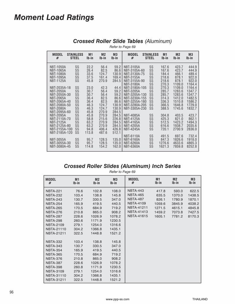
Crossed Roller Slide Tables (Aluminum)Refer to Page 69
NBT-1050ANBT-1065ANBT-1080ANBT-1095ANBT-1125A
NBT-2035A-18NBT-2050ANBT-2050A-30NBT-2065ANBT-2065A-40NBT-2080A-50NBT-2080ANBT-2095A-60NBT-2095ANBT-2110A-70NBT-2125ANBT-2125A-80NBT-2155A-100NBT-2185A-120
NBT-3055ANBT-3055A-30NBT-3080A-45
SSSSSSSSSS
SSSSSSSSSSSSSSSSSSSSSSSSSSSS
SSSSSS
22.226.433.637.545.8
23.030.730.736.436.446.346.345.845.858.863.263.294.8
113.8
95.795.7
114.8
56.482.5
124.7161.4270.9
42.356.456.482.582.5
124.7124.7270.9270.9215.6270.9270.9406.4487.6
128.5128.5154.2
59.286.6
130.9169.4284.5
44.459.259.286.686.6
130.9130.9284.5284.5226.8284.5284.5426.8512.1
135.0135.0162.0
MODEL STAINLESS M1 M2 M3# STEEL lb-in lb-in lb-in
NBT-3105ANBT-3105A-60NBT-3130A-75NBT-3155ANBT-3155A-90NBT-3180ANBT-3180A-105NBT-3205ANBT-3205A-130NBT-3230A-155NBT-3255A-180NBT-3280A-205NBT-3305A-230
NBT-4085ANBT-4125ANBT-4165A NBT-4205ANBT-4245A
NBT-6110ANBT-6160ANBT-6260ANBT-6360A
SSSSSSSSSSSSSSSSSSSSSSSSSS
SSSSSSSSSS
SSSSSSSS
167.6167.6184.4218.6218.6270.3270.3285.7285.7314.3336.3366.5388.5
304.8425.3512.5616.6720.1
491.5847.3
1276.61621.3
423.7423.7466.1878.1878.1
1109.01109.01283.61283.61412.01510.81646.81745.6
403.5821.0
1423.21938.72700.9
697.61826.64633.67859.8
444.9444.9489.4922.0922.0
1164.41164.41347.71347.71482.51586.21729.01832.7
423.7862.1
1494.32035.62836.0
732.41918.04865.38252.8
MODEL STAINLESS M1 M2 M3# STEEL lb-in lb-in lb-in
Crossed Roller Slides (Aluminum) Inch SeriesRefer to Page 69
NBTA-221NBTA-232NBTA-243NBTA-254NBTA-265NBTA-276NBTA-287NBTA-298NBTA-2109NBTA-21110NBTA-21211
NBTA-332NBTA-343NBTA-354NBTA-365NBTA-376NBTA-387NBTA-398NBTA-3109NBTA-31110NBTA-31211
76.6103.4130.7165.9170.5210.8228.6260.6279.1304.2322.5
103.4130.7165.9170.5210.8228.6260.8279.1304.2322.5
102.8138.8330.5419.5684.9865.0
1026.91171.91254.01366.81448.8
138.8330.5419.5684.9865.0
1026.91171.91254.01366.81448.8
108.0145.8347.0440.5719.2908.2
1078.21230.51316.61435.11521.2
145.8347.0440.5719.2908.2
1078.21230.51316.61435.11521.2
NBTA-443NBTA-465NBTA-487NBTA-4109NBTA-41211NBTA-41413NBTA-41615
417.8635.5826.1
1059.61271.51459.21605.1
593.01370.01780.93845.94615.17073.87781.2
622.51438.51870.14038.24845.87427.58170.3
MODEL M1 M2 M3# lb-in lb-in lb-in
MODEL M1 M2 M3# lb-in lb-in lb-in
Moment Load Ratings
96
www.ppp-ss.com THAILAND

Recirculating Ball Slide GuidesRefer to Page 81
BSGS5BSGS5UU
BSGS8BSGS8UU
BSG10BSG10UUBSGS10BSGS10UU
BSG13BSG13UUBSGS13BSGS13UU
BSG16BSG16UUBSGS16BSGS16UU
BSG25BSG25UUBSGS25BSGS25UU
10.6
36.5
60.8
78.1
190.9
451.4
13.3
43.4
69.5
95.5
225.7
538.3
MODEL#
M1lb-in
M2lb-in
M3lb-in
BSGS9WBSGS9WUU
BSG12WBSG12WUUBSGS12WBSGS12WUU
BSG14WBSG14WUUBSGS14WBSGS14WUU
BSG16WBSG16WUUBSGS16WBSGS16UU
95.5
121.5
329.9
355.9
112.9
147.6
190.9
425.4
138.9
269.1
460.1
1310.9
MODEL#
M1lb-in
M2lb-in
M3lb-in
Crossed Roller Slide Tables (Steel)Refer to Page 77
NBT-1025NBT-1035NBT-1045NBT-1055NBT-1065NBT-1075NBT-1085
NBT-2035NBT-2050NBT-2065NBT-2080NBT-2095NBT-2110NBT-2125NBT-2140NBT-2155NBT-2170NBT-2185
NBT-3055NBT-3080
6.08.1
10.213.216.218.320.4
28.143.752.666.773.784.291.2
101.8108.8119.3126.3
137.4200.8
7.814.322.535.049.665.383.1
36.075.5
116.9181.0236.5311.8382.8477.3563.8677.3779.5
174.5366.8
8.215.023.736.752.168.687.3
37.879.3
122.8190.1248.3327.4401.9501.1592.0711.2818.5
183.2385.1
NBT-3105NBT-3130NBT-3155NBT-3180NBT-3205NBT-3230NBT-3255NBT-3280NBT-3305
NBT-4085NBT-4125NBT-4165NBT-4205NBT-4245NBT-4285NBT-4325
NBT-6110NBT-6160NBT-6210NBT-6260NBT-6310
240.0300.0338.2387.3409.1458.2490.9534.6567.3
436.6608.1732.8881.0
1029.11161.61294.2
702.11211.11527.11825.52106.3
571.7881.2
1181.41568.21819.02219.12572.63011.73424.0
581.91182.21831.82740.63830.44968.56329.6
1108.82689.94370.86399.18725.7
600.3925.3
1240.41646.71910.02330.02701.23162.33595.2
611.01241.31923.42877.64021.95216.96646.1
1164.22824.44589.46719.09162.0
MODEL M1 M2 M3# lb-in lb-in lb-in
MODEL M1 M2 M3# lb-in lb-in lb-in
Moment Load Ratings
16.8
46.0
104.2
164.9
355.9
868.2
97
www.ppp-ss.com THAILAND

92
PRICE AND ENGINEERING CHANGES:Prices, specifications, and engineering information are subjectto change without notice. All prices, dimensions, andengineering information in previous catalogs, bulletins, andprice lists are superseded.
TERMS OF SALE:All prices are FOB our factory, Bethel, CT. Terms are net 30days. Purchase orders are accepted subject only to theconditions and warranty on this page despite conditions orstatements to the contrary contained in any purchase order.Risk of loss and title is with purchaser upon delivery to carrier.
Load ratings listed are based on symmetrical loading,theoretical data, and standard definitions of the bearingindustry. Maximum load ratings and all other information in thiscatalog are suggested only, and cannot be guaranteed orwarranted by Del-Tron Precision, Inc.. Suitability of the productsfor the intended use shall be solely determined by the user, andthe user shall assume all risk and liability therewith.
DELIVERY:Shipping dates, not delivery dates are acknowledged becausewe have no control over the performance of the carrier. Anyextension of delivery dates beyond those specified in theoriginal order must be approved by Del-Tron Precision, Inc.
DELAY:Del-Tron Precision, Inc. shall not be held responsible for anydelay or failure to manufacture or make delivery of all or anypart of the material ordered due to strikes or other labordisputes or labor troubles, fires, floods, droughts, accidents,insurrections, breakdowns of machinery or manufacturing plant,lack of or inability to obtain raw materials, labor, power orsupplies. Federal, State, County or Municipal laws, acts, rulesor regulations or any other causes, contingencies orcircumstances within or without the United States not subject tothe control of Del-Tron Precision, Inc. which prevent or hinderthe manufacture or delivery of the material ordered.
QUANTITY REDUCTION/CANCELLATIONNo returns if shipment is completed. Charges will be 100% P.O.Value. If order is complete (in-house), charges will be 100% P.O.Value less shipping charges. If order is incomplete (in-house),charges will be based on Actuals: Engineering time spent,Production labor utilized, Material ordered (if special), Materialused (if standard), and a 25% Administrative charge overcalculated costs.
RESTOCKING CHARGE:A 15% re-stocking charge based on value being returned, andthe customer will be responsible to pay the new adjustedquantity price.
ORDER HOLDS (INITIATED BY CUSTOMER):Time delays in shipments will require new delivery schedules tobe generated, and additional set-up charges or administrativecharges will be passed on to the customer.
WARRANTY, EXCLUSIVE REMEDIES & LIMITS OFLIABILITY:Del-Tron Precision, Inc.’s (“Del-Tron”) sole warranty forproducts is to repair and replace at no charge, products whichare defective in workmanship or materials, provided writtennotice of such defect is supplied to Del-Tron within the warrantyperiod and product is returned to factory without tampering ormisuse. No material may be returned under warranty withoutprior written authorization from Del-Tron. Del-Tron shall prepaythe return to purchaser of such authorized products. Thewarranty period is thirty (30) days after acceptance of theproducts. Product is deemed accepted when received bypurchaser unless Del-Tron is notified in writing within thirty (30)days setting forth in detail how product does not conform to itsmaterial specifications. Del-Tron will notify purchaser whensuch non conformities are corrected. If, by written noticereceived by Del-Tron within five (5) days following Del-Tron’snotification, you identify remaining non-conformities, Del-Tronwill correct such non conformities. When such non-conformitiesare corrected, the product shall be deemed accepted. Del-Tron’s liability for its product is limited to such replacement andDel-Tron shall have no liability for products mishandled ormisapplied by buyer or its customers.
THE WARRANTIES SET FORTH HEREIN REPLACEALL OTHER WARRANTIES, EXPRESS, STATUTORYOR IMPLIED, INCLUDING, BUT NOT LIMITED TO, THEIMPLIED WARRANTIES OF MERCHANTABILITY ANDFITNESS FOR A PARTICULAR PURPOSE.In all instances in which damages are sought from Del-Tronregardless of the legal theory upon which the claim is based,Del-Tron shall only be liable for (1) a bodily injury (includingdeath) and (2) damage to real property and tangible personalproperty for which Del-Tron is legally liable and the amount ofany other actual loss or damage arising from Del-Tron’sperformance or nonperformance pursuant to any Purchase upto the purchase price of the product that caused any damage.Under no circumstances will Del-Tron be liable for losses ordamages resulting from third party claims against you ordamages by you based upon third party claims (other thanthose specified in (1) and (2) above or your economicconsequential damages (including loss, profits or savings)),incidental damages or punitive damages even though Del-Tronknew of their possibility.
This section sets forth a maximum collective responsibility ofDel-Tron, its suppliers, subcontractors and agents, and all setsof parties are intended beneficiaries of this section. Thewarranty and exclusive remedy and liability limit is governed bythe laws of the State of Connecticut and can not be modified orvaried except in a writing signed by the purchaser and Del-Tron.
www.ppp-ss.com THAILAND