Filtration Systems Manual 12-07.pdf · Installing the Filter Housing ... mandatory for all users...
30
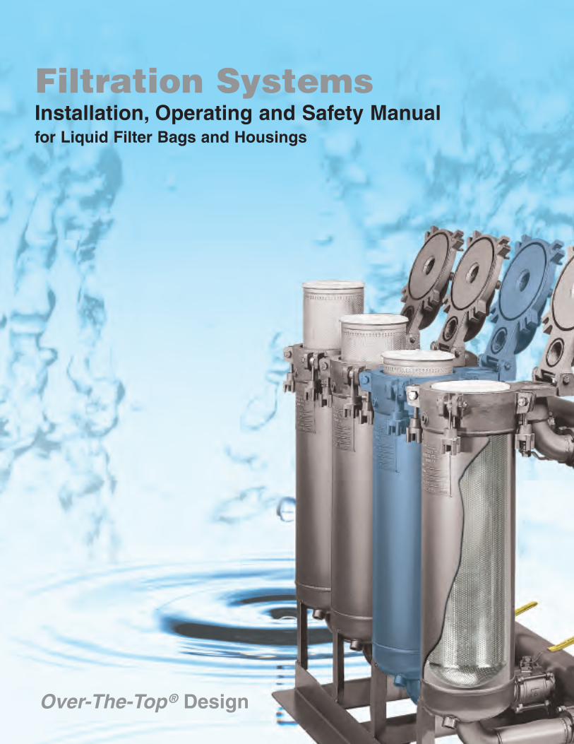
Filtration Systems Installation, Operating and Safety Manual for Liquid Filter Bags and Housings Over-The-Top ® Design
Transcript of Filtration Systems Manual 12-07.pdf · Installing the Filter Housing ... mandatory for all users...
Filtration SystemsInstallation, Operating and Safety Manualfor Liquid Filter Bags and Housings
Over-The-Top ® Design
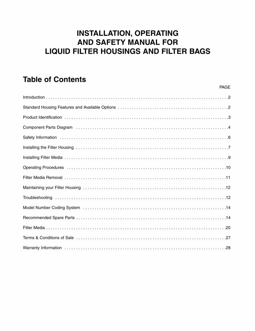
INSTALLATION, OPERATING AND SAFETY MANUAL FOR
LIQUID FILTER HOUSINGS AND FILTER BAGS
Table of ContentsPAGE
Introduction . . . . . . . . . . . . . . . . . . . . . . . . . . . . . . . . . . . . . . . . . . . . . . . . . . . . . . . . . . . . . . . . . . . . . . . . . . . . . . .2
Standard Housing Features and Available Options . . . . . . . . . . . . . . . . . . . . . . . . . . . . . . . . . . . . . . . . . . . . . . . .2
Product Identification . . . . . . . . . . . . . . . . . . . . . . . . . . . . . . . . . . . . . . . . . . . . . . . . . . . . . . . . . . . . . . . . . . . . . . .3
Component Parts Diagram . . . . . . . . . . . . . . . . . . . . . . . . . . . . . . . . . . . . . . . . . . . . . . . . . . . . . . . . . . . . . . . . . .4
Safety Information . . . . . . . . . . . . . . . . . . . . . . . . . . . . . . . . . . . . . . . . . . . . . . . . . . . . . . . . . . . . . . . . . . . . . . . . .6
Installing the Filter Housing . . . . . . . . . . . . . . . . . . . . . . . . . . . . . . . . . . . . . . . . . . . . . . . . . . . . . . . . . . . . . . . . . .7
Installing Filter Media . . . . . . . . . . . . . . . . . . . . . . . . . . . . . . . . . . . . . . . . . . . . . . . . . . . . . . . . . . . . . . . . . . . . . . .9
Operating Procedures . . . . . . . . . . . . . . . . . . . . . . . . . . . . . . . . . . . . . . . . . . . . . . . . . . . . . . . . . . . . . . . . . . . . .10
Filter Media Removal . . . . . . . . . . . . . . . . . . . . . . . . . . . . . . . . . . . . . . . . . . . . . . . . . . . . . . . . . . . . . . . . . . . . . .11
Maintaining your Filter Housing . . . . . . . . . . . . . . . . . . . . . . . . . . . . . . . . . . . . . . . . . . . . . . . . . . . . . . . . . . . . . .12
Troubleshooting . . . . . . . . . . . . . . . . . . . . . . . . . . . . . . . . . . . . . . . . . . . . . . . . . . . . . . . . . . . . . . . . . . . . . . . . . .12
Model Number Coding System . . . . . . . . . . . . . . . . . . . . . . . . . . . . . . . . . . . . . . . . . . . . . . . . . . . . . . . . . . . . . .14
Recommended Spare Parts . . . . . . . . . . . . . . . . . . . . . . . . . . . . . . . . . . . . . . . . . . . . . . . . . . . . . . . . . . . . . . . . .14
Filter Media . . . . . . . . . . . . . . . . . . . . . . . . . . . . . . . . . . . . . . . . . . . . . . . . . . . . . . . . . . . . . . . . . . . . . . . . . . . . . .20
Terms & Conditions of Sale . . . . . . . . . . . . . . . . . . . . . . . . . . . . . . . . . . . . . . . . . . . . . . . . . . . . . . . . . . . . . . . . .27
Warranty Information . . . . . . . . . . . . . . . . . . . . . . . . . . . . . . . . . . . . . . . . . . . . . . . . . . . . . . . . . . . . . . . . . . . . . .28
INTRODUCTION
Thank you for selecting Filtration Systems equipment for your liquid filtration requirements. Our Liquid FilterHousings and Systems are designed for use with High Performance Filter Bags, Cartridge Filters, or StrainerBaskets. This Installation, Operating & Safety Manual was prepared by professionals at Filtration Systems whoare concerned with your safety and satisfaction. By familiarizing yourself with this booklet, most of yourquestions about our products will be answered.
IF YOU HAVE ANY QUESTIONS, OR NEED OUR ASSISTANCE,PLEASE DO NOT HESITATE TO CALL US AT (954) 572-2700.
STANDARD HOUSING FEATURES
Over-The-Top® DesignBuilt to ASME Code StandardsInvestment Cast Lid and Body Hinged Lid with Handle, Built-in Lid Stop, and Safety DetentsPerforated T-316 S/S Support Basket with Longitudinal TaperGauge Ports, Vent Ports, Drain PortsO-Ring Grooves Machined into Housing Lid (Buna-N standard)Available in 150psi or 300psi Maximum Working Pressure
Over-The-Top® Housing Design Over-The-Top housing design, featured on all Filtration Systems vessels, maximizes filtration performance bypreventing bypass of unfiltered liquid. When the vessel is closed, the machined face of the lid compresses thetop of the Zero-Bypass® bag collar, forming an absolute seal. As there is no ‘dead-space’ between the top of thebag and the housing lid, unfiltered liquid cannot accumulate in the housing, eliminating clean up of the vesselinterior during change-out. The used bag, containing filtered solids, is simply removed and replaced with a cleanfilter bag.
AVAILABLE OPTIONS
• T-316 S/S Upgrade, Including S/S Hardware • Mesh & Micron Lined Baskets, S/S• Modified Flanged, Threaded, or Sanitary Connections • Perforated Strainer Baskets, S/S• Sanitary, Four-Position Butterfly Valves • Cartridge Chambers, S/S• Low-Profile, Horizontal Outlets • Two-Piece, S/S Thermal Jackets• Interior Polished Finishes, Including 3A Sanitary • Alternate Outlet Locations• HALAR® Fluoropolymer Lining • Additional Ports• Epoxy Coating, interior, exterior, and stand • Drain Valves, Vent Valves• SAFEsystem®, Safety Apparatus Filter Enhancement • Pressure Gauges• Actuated Valves, Electric or Pneumatic • Assorted O-Ring Materials
2
3
PRODUCT IDENTIFICATION
All Filtration Systems Filter Housings are stamped with a unique Serial Number that can be identified by ourfactory. Nameplates are permanently affixed to the pipe of each filter housing. Removal of the nameplate voidsthe product of any warranty and eliminates future identification of the product.
ASME Code Nameplate identifies both theNational Board Number and the Serial Number ofthe vessel. A "U" Stamp indicates that the Vesselhas been designed and manufactured inaccordance with the guidelines of ASME CodeSection 8, Division 1. Limits of safe workingpressures and temperatures are designated on thenameplate. Any repair or modification of a housingwith an ASME code plate voids the ASMEcertification of the housing.
An Industrial Grade Nameplate identifies theSerial Number of the Vessel, as well as the safelimits of working pressure and temperature.
A 3-A Sanitary Symbol Plate identifies the Vesselas being designed and built in accordance with 3-ASanitary standards, which establish design andfabrication criteria of product contact surfaces fordairy quality products.
A CE Plate identifies the vessel as being designedand built in accordance with the EuropeanPressure Equipment Directive. The Serial Numberand limits of safe working pressures andtemperatures are designated on the nameplate.Required for participating European membercountries only.
4
COMPONENT PARTSOVER-THE-TOP ® DESIGN
INDIVIDUAL FILTER HOUSING
O-RINGS
S/S SUPPORT BASKET
DOWNSTREAMGAUGE PORT
NAME PLATE
DOWNSTREAMDRAIN PORT
LID HANDLE
UPSTREAMGAUGE PORT
VENT PORT
LID STOP
UPSTREAMDRAIN PORT
INLET
BAR KNOBASSEMBLIES
ADJUSTABLETRIPOD STAND
OUTLETBOTTOM
HEAD
PIPE
BODY
LID
Note: Refer to Product Brochure for specific type of connections and complete specifications.
VENT PORTUPSTREAM
GAUGEPORT
DOWNSTREAMGAUGE PORT
NAMEPLATE
DOWNSTREAMDRAIN PORT
LID STOP
UPSTREAMDRAIN PORT
INLET
VALVEHANDLE
OUTLET
PIPE
BOTTOMHEAD
BODY
COMPONENT PARTSOVER-THE-TOP ® DESIGN
MULTI-HOUSING FILTER SYSTEM
BALL VALVE
UPSTREAMGAUGE PORT
VENT PORT
HANDLE
INLET INLET
DOWNSTREAMGAUGE PORT
OUTLET OUTLET
DOWNSTREAMDRAIN PORT
LID
TOP VIEW
FRONT VIEW
SIDE VIEW
Note: Refer to Product Brochure for specific type of connections and complete specifications.
5
6
SAFETY INFORMATION
Filtration Systems Filter Vessels are designed to filter liquids under pressure, in accordance with thetemperature and pressure restrictions stamped on the nameplate. The following procedures aremandatory for all users operating our Filter Vessels. Retain this manual, and any product relatedliterature for review by all personnel operating or supervising the operation of this equipment.
• Follow the Installation, Operating, and Safety Instructions in this Manual.• Wear protective garments, splash protection, eye protection and respirators, as required.• Always check chemical and thermal compatibility of Housing Material, O-Rings, Gaskets, and Media with
the fluid being filtered. Consult a liquid compatibility guide or ask your local dealer. Fluid compatibility includes all materials in contact with the liquid under elevated pressures and temperatures.
• Before pressurizing a Filter Vessel, always make sure you have fastened the Lid Hardware.• O-Rings are subject to wear and should be checked each time the Filter Vessel is opened. Replace
O- rings prior to pressurization of the Filter Vessel. Be certain that the O-Ring material is both chemically and thermally compatible with the fluid being filtered.
• Always relieve pressure to the system before loosening the Lid Hardware or opening the Vessel Lid.• In certain operating environments, static electrical charges or sparks may cause combustion or
explosion of volatile materials. Properly ground equipment, as required.• Removing Filter Media from packaging may produce static electrical sparks. To avoid risk of combustion
or explosion, never open static packaging in or around areas containing potentially flammable or explosive materials, liquids or gases.
• Disposal of Filter Media: A Filter Bag that has been used with a hazardous liquid may contain residual amounts of this material and should be handled with the same safeguards that would be used in handling hazardous and/or toxic material. Dispose of Media in accordance with Federal, State, and/or Local laws or requirements.
Improper use of Filter Vessels may result in injury or property damage. Any misuse or modification toour products will void both the manufacturer’s warranty as well as the ASME certification of ASME CodeVessels. Safety Information does not by itself eliminate any danger. Information or warnings are not asubstitute for proper accident prevention measures.
Lethal ServiceFiltration Systems Vessels are not designed for Lethal Service. "Lethal Service" refers toVessels containing lethal substances, poisonous gases, or liquids of such a nature that avery small amount of the gas or vapor of the liquid (mixed or unmixed) is dangerous tolife when inhaled. In addition, substances of this nature that are stored under pressure,or may generate pressure if stored in a closed Vessel, are considered lethal.
7
INSTALLING THE FILTER HOUSING
Unpacking the Equipment
Carefully remove the Housing from carton or pallet and check for damage.
Remove and save all product literature shipped inside the Housing or Support Basket.
Remove protective covers from flanged or sanitary connections.
Halar ® Lined Housings and Vessels with Interior Polished Finishes are specially wrapped for additionalprotection. To prevent damage to the surface finish, use care when unpacking.
Confirm that the specifications and flow rate parameters have been checked against operating conditions.Housing flow rates, listed in product brochures, are based on water in a Housing without Filter Media. Actual flowrates are determined by the specific Filter Media, as well as the characteristics of the application.
Do not exceed maximum allowable Pressure or Temperature stamped on the nameplate of the Housing.
Removal of the Nameplate voids the Product Warranty and eliminates future identification of the product.
Welding to the Housing will void the Product Warranty and the Code Status of ASME Housings.
Halar is a registered Trademark of Solvay Solexis, Inc.
Individual Housings & Valved, Individual Housings
Anchor the Tripod Stand to the floor or stable base.
Loosen the bolts on the Tripod Stand and raise or lower the housing as necessary, to accommodate pipingrequirements.
Multi-Housing Systems
Place the Frame on a secure, level surface.
If the unit is non-valved, a shut-off Valve should be installed before and after the Filter System, allowing the unitto be shut down during Media change-out. Valved, modular filter systems allow individual Housings to beisolated for Media change-out so there is no disruption of service.
Multi-Housing Systems are equipped with two Inlet and two Outlet connections, located on the Inlet (top) andOutlet (bottom) headers. Choose the Inlet and Outlet Site(s) to accommodate space and/or piping requirements.Seal any unused connections with a (user-furnished) blind flange or threaded plug.
8
INSTALLING THE FILTER HOUSING, CONTINUED
General Installation Notes
• The direction of liquid flow is from the Inlet (top) through the Outlet (bottom) of the Housing. Always pumpthrough the Filter Housing. The discharge of the pump should feed the Inlet of the Housing.
• If there is a possibility of backflow to the Housing when the system is turned off, install an outlet valve toprotect the filter media.
• Do not pipe to exact Housing dimensions. Pre-pipe to the general area where the system will be installed,then connect from the Housing to the piping. Do not force or bend the Filter Housing out of line when piping.
• Threaded Connections: We recommend the use of a thread sealant.
• Flanged Connections: Confirm that the gaskets used are compatible with the application.
• Clean the Filter Housing(s) before installation.
• Flush the system of any debris that may have resulted from installation.
• All Housings are Hydrostatically Tested (tested with water, under pressure) prior to shipment. Do not test withair or gas.
• Vent Ports, Drain Ports and Gauge Ports are standard on all Filtration Systems Housings. Install auxiliaryValves and Gauges in the appropriate ports at this time:
A Vent Valve should be installed in the Vent Port on the Lid(s).
Pressure Gauges, used to monitor differential pressure, should be installed in the Gauge Ports on the Lid and the Filter Vessel Body of each Housing.
Drain Valves should be installed in the Drain Ports on the Bottom Head of the Housing and on the Body for the collection of residual liquid.
• Seal unused Vent, Drain, or Gauge Ports prior to start-up.
• Confirm that the O-Rings have been properly installed in the Lid of each Housing.
• Install a Perforated Support Basket in each Housing. Follow instructions below for INSTALLING FILTER BAGS.
• If the Housing is to be used with a Lined Basket or Strainer, install it with the appropriate sealing gasket.
9
INSTALLING FILTER MEDIA
Installing Filter Bags
1. Take the housing "off-line" (follow the SHUT DOWN PROCEDURES in the OPERATING Section).After draining and venting the Housing, loosen the four Bar Knob Assemblies from the Lid, and lay them back through the slots provided. Open the Vessel Lid using the Lid Handle, and tilt it back completely.Remove the used Filter Bag (follow procedures for FILTER BAG REMOVAL).
2. Be certain that a Perforated Support Basket is in place. The use of a Support Basket is mandatory with Filter Bags.
3. Select the appropriate Accufit ® or Ultrafit ® Welded Liquid Filter Bag. Check chemical and thermal compatibility of the Filter Media to be used in an application. Accufit and Ultrafit Welded Liquid Filter Bags have the model number, including the micron rating, embossed on the outside of each Filter Bag.
4. Remove the Filter Bag from the plastic bag. Removing Filter Media from packaging may produce static electrical sparks. To avoid risk of combustion or explosion, never open static packaging in or around areas containing potentially flammable or explosive materials, liquids or gases.
5. Insert the Filter Bag into the Support Basket. The round bottom of the Filter Bag is designed to conform to the shape of the Support Basket. Be certain that the Filter Bag is fully extended and supported by the Basket, completely and evenly. Push down on the Bag Collar so it sits flush with the top of the flanged lip of the Support Basket.
Note: Our Filter Bags, by design, are longer than the Support Basket. The additional length ensures thatthe Bag remains fully supported by the Basket during use.
Improper Filter Bag installation can result in Filter Bag breakage.
To facilitate Filter Bag installation, a Filter Bag Insert (sold separately) will eliminate the need for technicians to reach into the Bag during installation.
Alternately, users can be assured that the Filter Bag is properly seated and fully extended by placing a Filter Bag Restrainer (sold separately) into the Bag, then installing the Bag (with Restrainer) into the Basket. The Restrainer remains in the Bag during the filtering process to keep it extended and maximizeits usable surface area. This accessory can prevent the Bag from "floating" as a result of backpressure.
Installing Large Diameter Cartridge Filters
1. Place the Cartridge Chamber into the Housing, in lieu of a Support Basket. Be certain theappropriate sealing gasket is used and installed properly under the flanged lip of the Cartridge Chamber.
2. Select the appropriate SEDTEK ® Cartridge. Removing Filter Media from packaging may producestatic electrical sparks. To avoid risk of combustion or explosion, never open static packaging in oraround areas containing potentially flammable or explosive materials, liquids or gases.
3. Insert the Cartridge into the Chamber. Secure the cartridge by pushing down, so the doubleO-Rings are seated into the machined coupling at the bottom of the Cartridge Chamber.
Filtration occurs by capturing particles throughout thedepth of the media. As a result, single-use filter mediais disposable and cannot be washed or reused.
10
OPERATING PROCEDURES
Lid Sealing Procedure
1. Confirm that the appropriate O-Rings and Filter Media have been installed properly.
2. Close the Lid of the Vessel using the Lid Handle, being careful not to drop it.
3. Bring the four Bar Knob Assemblies up into position. Hand-tighten bolts in a diagonal pattern, then torque to specification in the same manner. To ensure a secure seal, we recommend 30-50 ft./lbs.of torque on the hold-down bolts.
Start Up Procedure
1. Open the Vent Valve.
2. Gradually fill the Vessel with liquid by opening the Inlet Valve slowly. As liquid enters the Vessel, air is allowed to escape through the Vent Valve to prevent an air pocket from forming.
3. At the first sign of liquid immerging through the Vent Valve, immediately close the Vent Valve and open the Outlet Valve, allowing liquid to flow through the Filter Housing. This begins the filtration process.
4. Monitor the Upstream and Downstream pressure with Gauges, when the Filter Vessel is "on-line". The difference between the two readings is known as the "pressure differential", measured across the Filter Bag. Increased upstream pressure indicates "blinding", and the need for Filter Bag replacement. Follow the Filter Bag manufacturer’s recommendation for maximum allowable differential pressure.
Shut Down Procedure
1. Stop the flow of liquid to the Vessel by closing the Inlet Valve.
2. Close the Outlet Valve to isolate the Housing from the liquid flow.
3. Observe the pressure and temperature closely. Proceed to Step 4 only if the parameters are within safe limits.
4. The Vessel is still in a pressurized state. Slowly open the Downstream Drain Valve located at the bottom of the Filter Vessel, and capture the liquid in an appropriate container (i.e. suitable for the filtered material that you are evacuating). Safeguards should be taken to wear protective clothing suitable for the material being handled.
5. Open the Vent Valve located on the top of the Filter Vessel Lid. This will promote faster gravity drainage when used in conjunction with the Downstream Drain Valve.
6. Open the Inlet Drain Valve located on the Body. If there is any unfiltered residual liquid, collect it in a suitable container.
7. Loosen the four Bar Knob Assemblies from the Lid, and lay them back through the slots provided. Openthe Vessel Lid using the Lid Handle, and tilt it back completely. The Media may now be removed for replacement (follow procedures for FILTER MEDIA REMOVAL).
11
FILTER MEDIA REMOVAL
Safeguards should be taken to wear protective clothing suitable for the material being handled.
Filter Media must be changed at or before the maximum differential pressure, recommended by themanufacturer. If the Filter Media is not changed on a timely basis, it will become "blinded" and will not drain.
Filter Bag Removal
1. Be certain the liquid has been drained from the Housing and Filter Bag (see SHUT DOWN PROCEDURES).
2. Grasp the Filter Bag Handles and pull the Collar inward to loosen the upper section of the Bag. Twist theCollar in a circular motion to release the cloth that may be embedded in the perforations of the Support Basket.
3. Anchor the Support Basket Flange while pulling the Filter Bag out of the Basket. If the Bag does not come loose easily, twist the Collar in a circular motion when pulling up.
Large Diameter Filter Cartridge Removal
1. Be certain the liquid has been drained from the Housing, Chamber, and Cartridge (see SHUT DOWN PROCEDURES).
2. When a Cartridge is fully loaded, unfiltered debris will accumulate within the Cartridge Chamber, eliminating the need to clean the Housing during change-out. Do not remove the Cartridge from the Chamber while it is in the Housing.
3. Remove the Chamber and Cartridge from the Housing to minimize spills and exposure.4. Grasp the built-in Handle on the Cartridge and pull it out of the Chamber.
Disposal of Filter MediaA Filter Bag or Cartridge that has been used with a hazardous liquid maycontain residual amounts of this material and should be handled with the same safeguards that would be used in handling any hazardous and/or toxic material.It is the user’s responsibility to dispose of all Filter Media in accordance with Federal, State, and/or Local laws or requirements.
Filtration occurs by capturing particlesthroughout the depth of the media. As a result,single-use filter media is disposable and cannotbe washed or reused.
12
MAINTAINING YOUR FILTER HOUSING
O-Rings"O-Rings" are subject to wear and should be checked for dirt, cuts, or swelling each time the Filter Vessel isopened. Replacement of O-Rings should be done prior to pressurization of the Filter Vessel. Be certain that the O-Ring material is both chemically and thermally compatible with the fluid being filtered (see page 18 forreplacement O-Rings).
HardwareLid Sealing Hardware should be checked each time the Filter Vessel is opened. Inspect the Eye Bolts forelongation or thread wear, due to excessive tightening. Check all components of the Bar Knob Assembly forcorrosion, and replace if necessary (see page 15 for replacement Hardware).
Ball Valve MaintenanceFiltration Systems Valved Housings are constructed with 2" S/S, Three-Piece, Full-Port Ball Valves, with TeflonSeals and Gaskets. Periodically flush the system to prevent build-up of particulate in the Body of the Valve.Replace worn Seals when necessary (see page 19 for replacement Valves & Seals).
Changing Hardware or Ball Valves may produce sparks. Properly ground equipment as required.
TROUBLESHOOTING
Housing Leaks… All Filtration Systems Vessels are hydrostatically tested at our factory to assure the integrityof the Housing. If a Housing leaks:
• Confirm that the O-Rings are in place, and properly installed. Check O-Rings for dirt, cuts, or swellingand replace, if necessary.
• Check the Lid Sealing Procedure; apply the recommended torque pressure and reseal the Housing.• Make sure that both the Inlet and Outlet Shut-Off Valves are open for filtering.• Check all threaded connections; use a threading compound product, as required.• Check plumbing connections.• Check the Housing Body to determine if it was bent out of line during installation. Apply a straight edge
over the machined face of the Housing Body from front to back. The straight edge should sit flush onthe Body, without gaps.
Ball Valves…
• If the Ball Valve is leaking, identify the leak origin and replace the Seals and Packing.• If the Valve is difficult to open and close, remove the Valve Body and check for obstructions inside the
Valve. After removing any debris, replace the body of the Valve.• Check the Valve Handle for straightness. Our Valves have built-in ‘Stops’. If the Handle is bent it will give
a false ‘Stop’ position. The Valve may appear closed, when it remains slightly open. If this occurs, replacethe Valve Handle.
• If the Valves don’t fully open or close, the ‘Stop’ or the Handle Slot engaging the Valve Stem, may bemisshapen, due to excessive force. Remove the Valve Handle and check the ‘Stop’ and the Machined Slot for distortion. If either is distorted, replace the Handle.
Surface Stains…
Stains may occur on stainless steel Housing surfaces, due to either process or atmospheric conditions.If surface staining occurs, it can be easily removed with a clean stainless steel wire brush or an aluminum oxidegrinding wheel.
13
Abnormally Short Filter Bag Life…
• Check the position of the Filter Bag in the Support Basket. Be certain that the Filter Bag is fully extendedand supported by the Basket.
• Check if the Filter Bag has been ripped or torn.• Excessive flow rates may require the user to increase the number of Filter Bags and Filter Housings
operating in parallel. As a general rule, adding a second Filter running in parallel will give you three times the Filter Bag life as a single filter. Reducing the flow rate to a Housing will allow increased loadingcapacity and promotes longer Filter Bag life.
Bag Breakage… Possible causes of Bag breakage:
Excessive flow rates or differential pressureChemical or thermal incompatibility with the Filter BagImproper Filter Bag installation (i.e. Bag not fully extended in the Basket)Bag floating due to backflow in the systemInstallation of the Bag before the Housing is fully drainedInstallation of the Bag without a Support Basket
• Check for process changes or changes in the liquid being filtered.• Check chemical and thermal compatibility.• Check proper Filter Bag installation procedures (see INSTALLING FILTER MEDIA).• Check to see if the Filter Bag is dirty and "blinded".• Do not exceed the Manufacturer’s recommended maximum temperature or flow rate parameters.• Do not exceed the Manufacturer’s recommendations for maximum allowable differential pressure.• Be certain that Gauges are accurate and in proper working order.
Particle Characterization AnalysisFiltration Systems offers Particle Characterization Studies of liquid samples.Particle Analysis provides meaningful data, useful in specifically identifying filtration requirements for the selection of equipment and Filter Media.Please contact Technical Services Department for details.
Filtration occurs by capturing particlesthroughout the depth of the media. As a result,single-use filter media is disposable and cannotbe washed or reused.
14
RECOMMENDED SPARE PARTS
Record the Model and Serial Number for ease of ordering spare parts.
VESSEL MODEL NUMBER __________________________________________________
SERIAL NUMBER(S)________________________________________________________
YEAR BUILT (ASME CODE VESSELS) ________________________________________
FILTER BAG MODEL NUMBER AND MICRON RATING ____________________________
Spare parts may be ordered from your Distributor or:
Filtration SystemsDivision of Mechanical Mfg. Corp.
10304 NW 50th StreetSunrise, FL 33351
Phone: 954-572-2700Fax: 954-572-3401
www.filtrationsystems.com
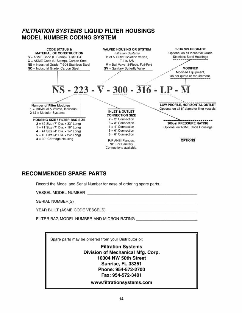
FILTRATION SYSTEMS LIQUID FILTER HOUSINGSMODEL NUMBER CODING SYSTEM
NS - 223 - V - 300 - 316 - LP - M
HOUSING SIZE / FILTER BAG SIZE2 = #2 Size (7" Dia. x 33" Long)1 = #1 Size (7" Dia. x 16" Long)4 = #4 Size (4" Dia. x 14" Long)5 = #5 Size (4" Dia. x 24" Long)3 = 30" Cartridge Housing
Number of Filter Modules1 = Individual & Valved, Individual2-12 = Modular Systems INLET & OUTLET
CONNECTION SIZE2 = 2" Connection3 = 3" Connection4 = 4" Connection6 = 6" Connection8 = 8" Connection
R/F ANSI Flanges,NPT, or Sanitary
Connections available.
300psi PRESSURE RATINGOptional on ASME Code Housings
LOW-PROFILE, HORIZONTAL OUTLETOptional on all 8" diameter filter vessels.
OPTIONS
CODE STATUS &MATERIAL OF CONSTRUCTION
S = ASME Code (U-Stamp), T-316 S/SC = ASME Code (U-Stamp), Carbon SteelNS = Industrial Grade, T-304 Stainless SteelNC = Industrial Grade, Carbon Steel
VALVED HOUSING OR SYSTEMFiltration Systems
Inlet & Outlet Isolation Valves,T-316 S/S
V = Ball Valve, 3-Piece, Full-Port SV = Sanitary Butterfly Valve
T-316 S/S UPGRADEOptional on all Industrial Grade
Stainless Steel Housings
MODIFIEDModified Equipment,
as per quote or requirement.
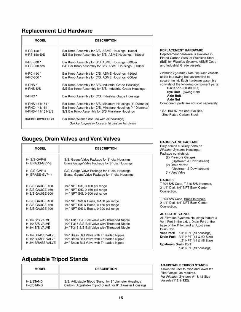
GAUGE/VALVE PACKAGEFully equips auxiliary ports on Filtration Systems Housings.Package consists of:
(2) Pressure Gauges (Upstream & Downstream)
(2) Drain Valves(Upstream & Downstream)
(1) Vent Valve
GAUGEST-304 S/S Case, T-316 S/S Internals,2 1/4" Dial, 1/4" NPT Back CenterConnection.
T-304 S/S Case, Brass Internals, 2 1/4" Dial, 1/4" NPT Back CenterConnection.
AUXILIARY VALVESAll Filtration Systems Housings feature aVent Port in the Lid, a Drain Port at thebase of the Filter, and an UpstreamDrain Port.Vent Port: 1/4" NPT (all housings)Drain Port: 3/4" NPT (#1 & #2 Size)
1/2" NPT (#4 & #5 Size) Upstream Drain Port:
1/4" NPT (all housings)
ADJUSTABLE TRIPOD STANDSAllows the user to raise and lower theFilter Vessel, as required.For Filtration Systems #1 & #2 SizeVessels (112 & 122).
H-RS-150 *H-RS-150-S/S
H-RS-300 *H-RS-300-S/S
H-RC-150 *H-RC-300 *
H-RNS *H-RNS-S/S
H-RNC *
H-RNS-141/151 *H-RNC-141/151 *H-RNS-141/151-S/S
BARKNOBWRENCH
Bar Knob Assembly for S/S, ASME Housings -150psiS/S Bar Knob Assembly for S/S, ASME Housings - 150psi
Bar Knob Assembly for S/S, ASME Housings -300psiS/S Bar Knob Assembly for S/S, ASME Housings - 300psi
Bar Knob Assembly for C/S, ASME Housings -150psiBar Knob Assembly for C/S, ASME Housings -300psi
Bar Knob Assembly for S/S, Industrial Grade HousingsS/S Bar Knob Assembly for S/S, Industrial Grade Housings
Bar Knob Assembly for C/S, Industrial Grade Housings
Bar Knob Assembly for S/S, Miniature Housings (4" Diameter)Bar Knob Assembly for C/S, Miniature Housings (4" Diameter)S/S Bar Knob Assembly for S/S Miniature Housings
Bar Knob Wrench (for use with all housings)Quickly torques or loosens lid closure hardware
Replacement Lid Hardware
H- S/S-GVP-8H- BRASS-GVP-8
H- S/S-GVP-4H- BRASS-GVP- 4
H-S/S GAUGE-100H-S/S GAUGE-160H-S/S GAUGE-300
H-S/B GAUGE-100H-S/B GAUGE-160H-S/B GAUGE-300
H-1/4 S/S VALVEH-1/2 S/S VALVEH-3/4 S/S VALVE
H-1/4 BRASS VALVEH-1/2 BRASS VALVEH-3/4 BRASS VALVE
S/S, Gauge/Valve Package for 8" dia. HousingsBrass Gauge/Valve Package for 8" dia. Housings
S/S, Gauge/Valve Package for 4" dia. HousingsBrass, Gauge/Valve Package for 4" dia. Housings
1/4" NPT S/S, 0-100 psi range1/4" NPT S/S, 0-160 psi range1/4" NPT S/S, 0-300 psi range
1/4" NPT S/S & Brass, 0-100 psi range1/4" NPT S/S & Brass, 0-160 psi range1/4" NPT S/S & Brass, 0-300 psi range
1/4" T-316 S/S Ball Valve with Threaded Nipple1/2" T-316 S/S Ball Valve with Threaded Nipple3/4" T-316 S/S Ball Valve with Threaded Nipple
1/4" Brass Ball Valve with Threaded Nipple1/2" Brass Ball Valve with Threaded Nipple3/4" Brass Ball Valve with Threaded Nipple
Gauges, Drain Valves and Vent Valves
H-S/STANDH-C/STAND
S/S, Adjustable Tripod Stand, for 8" diameter HousingsCarbon, Adjustable Tripod Stand, for 8" diameter Housings
Adjustable Tripod Stands
REPLACEMENT HARDWAREReplacement hardware is available inPlated Carbon Steel or Stainless Steel(S/S) for Filtration Systems ASME Codeand Industrial Grade vessels.
Filtration Systems Over-The-Top ® vesselsutilize four swing bolt assemblies tosecure the lid. Each hardware assemblyconsists of the following component parts:
Bar Knob (Castle Nut)Eye Bolt (Swing Bolt)Axle BoltAxle Nut
Component parts are not sold separately.
* SA-193-B7 rod end Eye Bolt,Zinc Plated Carbon Steel.
DESCRIPTIONMODEL
DESCRIPTIONMODEL
DESCRIPTIONMODEL
15
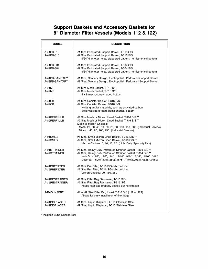
A-#1PB-316A-#2PB-316
A-#1PB-304A-#2PB-304
A-#1PB-SANITARYA-#2PB-SANITARY
A-#1MBA-#2MB
A-#1CB A-#2CB
A-#1PERF-MLB A-#2PERF-MLB
A-#1SMLB A-#2SMLB
A-#1STRAINER A-#2STRAINER
A-#1PREFILTER A-#2PREFILTER
A-#1RESTRAINERA-#2RESTRAINER
A-BAG INSERT
A-#1DISPLACERA-#2DISPLACER
#1 Size Perforated Support Basket, T-316 S/S #2 Size Perforated Support Basket, T-316 S/S
9/64” diameter holes, staggered pattern; hemispherical bottom
#1 Size Perforated Support Basket, T-304 S/S#2 Size Perforated Support Basket, T-304 S/S
9/64” diameter holes, staggered pattern; hemispherical bottom
#1 Size, Sanitary Design, Electropolish, Perforated Support Basket#2 Size, Sanitary Design, Electropolish, Perforated Support Basket
#1 Size Mesh Basket, T-316 S/S #2 Size Mesh Basket, T-316 S/S
8 x 8 mesh; cone-shaped bottom
#1 Size Canister Basket, T-316 S/S#2 Size Canister Basket, T-316 S/S
Holds granular materials, such as activated carbon Solid wall; perforated, hemispherical bottom
#1 Size Mesh or Micron Lined Basket, T-316 S/S **#2 Size Mesh or Micron Lined Basket, T-316 S/S **Mesh or Micron Choices:
Mesh: 20, 30, 40, 50, 60, 70, 80, 100, 150, 200 (Industrial Service)Micron: 40, 90, 160, 250 (Industrial Service)
#1 Size, Small Micron Lined Basket, T-316 S/S **#2 Size, Small Micron Lined Basket, T-316 S/S **
Micron Choices: 5, 10, 15, 25 (Light Duty, Specialty Use)
#1 Size, Heavy Duty Perforated Strainer Basket, T-304 S/S **#2 Size, Heavy Duty Perforated Strainer Basket, T-304 S/S **
Hole Size: 1/2”, 3/8”, 1/4”, 3/16”, 9/64”, 3/32”, 1/16”, 3/64”Decimal: (.500)(.375)(.250)(.1875)(.1407)(.0938)(.0625)(.0469)
#1 Size Pre-Filter, T-316 S/S- Micron Lined#2 Size Pre-Filter, T-316 S/S- Micron Lined
Micron Choices: 90, 160, 250
#1 Size Filter Bag Restrainer, T-316 S/S#2 Size Filter Bag Restrainer, T-316 S/S
Keeps filter bag properly seated during filtration
#1 or #2 Size Filter Bag Insert, T-316 S/S (112 or 122)Allows for easy installation of filter bags
#1 Size, Liquid Displacer, T-316 Stainless Steel#2 Size, Liquid Displacer, T-316 Stainless Steel
Support Baskets and Accessory Baskets for 8" Diameter Filter Vessels (Models 112 & 122)
* Includes Buna-Gasket Seal
MODEL DESCRIPTION
16
17
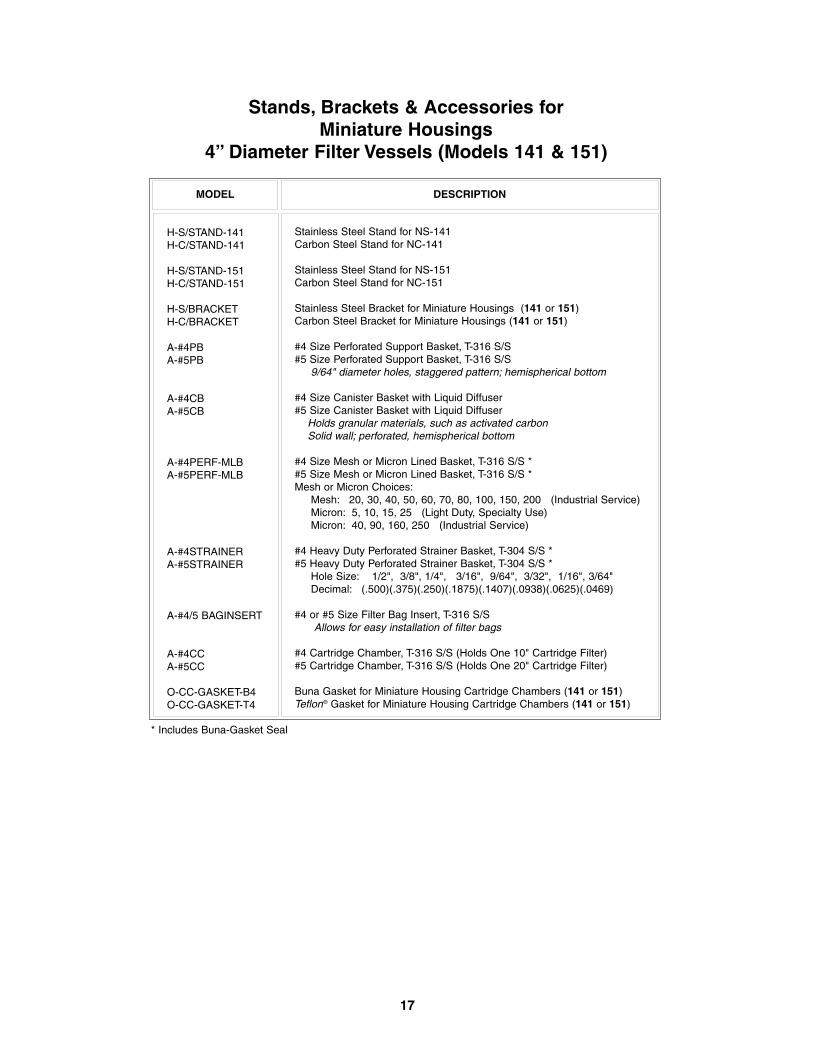
H-S/STAND-141H-C/STAND-141
H-S/STAND-151H-C/STAND-151
H-S/BRACKETH-C/BRACKET
A-#4PBA-#5PB
A-#4CBA-#5CB
A-#4PERF-MLBA-#5PERF-MLB
A-#4STRAINERA-#5STRAINER
A-#4/5 BAGINSERT
A-#4CCA-#5CC
O-CC-GASKET-B4O-CC-GASKET-T4
Stainless Steel Stand for NS-141Carbon Steel Stand for NC-141
Stainless Steel Stand for NS-151Carbon Steel Stand for NC-151
Stainless Steel Bracket for Miniature Housings (141 or 151)Carbon Steel Bracket for Miniature Housings (141 or 151)
#4 Size Perforated Support Basket, T-316 S/S#5 Size Perforated Support Basket, T-316 S/S
9/64" diameter holes, staggered pattern; hemispherical bottom
#4 Size Canister Basket with Liquid Diffuser#5 Size Canister Basket with Liquid Diffuser
Holds granular materials, such as activated carbonSolid wall; perforated, hemispherical bottom
#4 Size Mesh or Micron Lined Basket, T-316 S/S *#5 Size Mesh or Micron Lined Basket, T-316 S/S *Mesh or Micron Choices:
Mesh: 20, 30, 40, 50, 60, 70, 80, 100, 150, 200 (Industrial Service)Micron: 5, 10, 15, 25 (Light Duty, Specialty Use) Micron: 40, 90, 160, 250 (Industrial Service)
#4 Heavy Duty Perforated Strainer Basket, T-304 S/S *#5 Heavy Duty Perforated Strainer Basket, T-304 S/S *
Hole Size: 1/2", 3/8", 1/4", 3/16", 9/64", 3/32", 1/16", 3/64" Decimal: (.500)(.375)(.250)(.1875)(.1407)(.0938)(.0625)(.0469)
#4 or #5 Size Filter Bag Insert, T-316 S/SAllows for easy installation of filter bags
#4 Cartridge Chamber, T-316 S/S (Holds One 10" Cartridge Filter)#5 Cartridge Chamber, T-316 S/S (Holds One 20" Cartridge Filter)
Buna Gasket for Miniature Housing Cartridge Chambers (141 or 151)Teflon® Gasket for Miniature Housing Cartridge Chambers (141 or 151)
Stands, Brackets & Accessories for Miniature Housings
4” Diameter Filter Vessels (Models 141 & 151)
* Includes Buna-Gasket Seal
MODEL DESCRIPTION
18
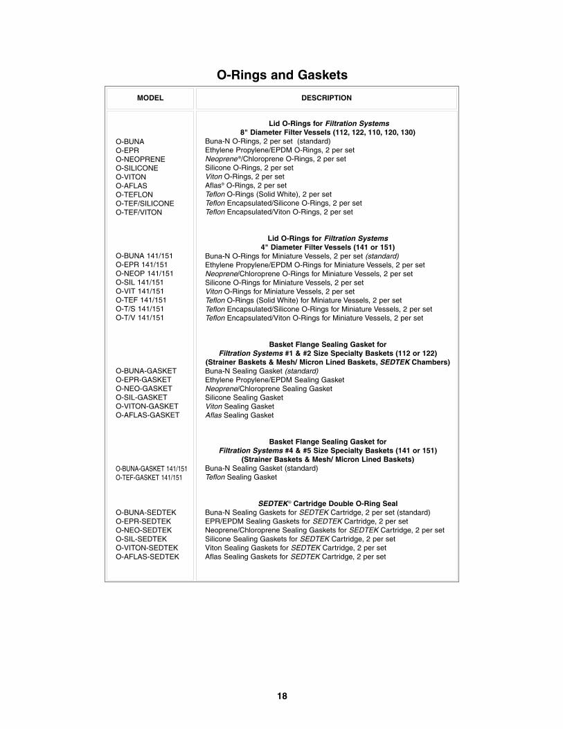
O-BUNAO-EPRO-NEOPRENEO-SILICONEO-VITONO-AFLASO-TEFLONO-TEF/SILICONEO-TEF/VITON
O-BUNA 141/151O-EPR 141/151O-NEOP 141/151O-SIL 141/151O-VIT 141/151O-TEF 141/151O-T/S 141/151O-T/V 141/151
O-BUNA-GASKETO-EPR-GASKETO-NEO-GASKETO-SIL-GASKETO-VITON-GASKETO-AFLAS-GASKET
O-BUNA-GASKET 141/151O-TEF-GASKET 141/151
O-BUNA-SEDTEKO-EPR-SEDTEKO-NEO-SEDTEKO-SIL-SEDTEKO-VITON-SEDTEKO-AFLAS-SEDTEK
Lid O-Rings for Filtration Systems8" Diameter Filter Vessels (112, 122, 110, 120, 130)
Buna-N O-Rings, 2 per set (standard)Ethylene Propylene/EPDM O-Rings, 2 per setNeoprene ®/Chloroprene O-Rings, 2 per setSilicone O-Rings, 2 per setViton O-Rings, 2 per setAflas® O-Rings, 2 per setTeflon O-Rings (Solid White), 2 per setTeflon Encapsulated/Silicone O-Rings, 2 per setTeflon Encapsulated/Viton O-Rings, 2 per set
Lid O-Rings for Filtration Systems4" Diameter Filter Vessels (141 or 151)
Buna-N O-Rings for Miniature Vessels, 2 per set (standard)Ethylene Propylene/EPDM O-Rings for Miniature Vessels, 2 per setNeoprene/Chloroprene O-Rings for Miniature Vessels, 2 per setSilicone O-Rings for Miniature Vessels, 2 per setViton O-Rings for Miniature Vessels, 2 per setTeflon O-Rings (Solid White) for Miniature Vessels, 2 per setTeflon Encapsulated/Silicone O-Rings for Miniature Vessels, 2 per setTeflon Encapsulated/Viton O-Rings for Miniature Vessels, 2 per set
Basket Flange Sealing Gasket for Filtration Systems #1 & #2 Size Specialty Baskets (112 or 122)
(Strainer Baskets & Mesh/ Micron Lined Baskets, SEDTEK Chambers)Buna-N Sealing Gasket (standard)Ethylene Propylene/EPDM Sealing Gasket Neoprene/Chloroprene Sealing Gasket Silicone Sealing Gasket Viton Sealing Gasket Aflas Sealing Gasket
Basket Flange Sealing Gasket for Filtration Systems #4 & #5 Size Specialty Baskets (141 or 151)
(Strainer Baskets & Mesh/ Micron Lined Baskets)Buna-N Sealing Gasket (standard) Teflon Sealing Gasket
SEDTEK® Cartridge Double O-Ring SealBuna-N Sealing Gaskets for SEDTEK Cartridge, 2 per set (standard)EPR/EPDM Sealing Gaskets for SEDTEK Cartridge, 2 per setNeoprene/Chloroprene Sealing Gaskets for SEDTEK Cartridge, 2 per set Silicone Sealing Gaskets for SEDTEK Cartridge, 2 per set Viton Sealing Gaskets for SEDTEK Cartridge, 2 per setAflas Sealing Gaskets for SEDTEK Cartridge, 2 per set
O-Rings and Gaskets
MODEL DESCRIPTION
19
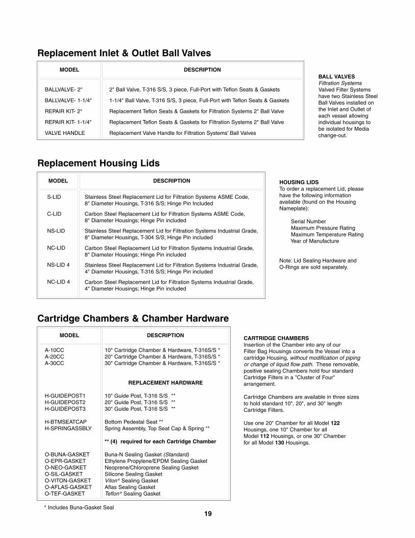
BALL VALVESFiltration SystemsValved Filter Systemshave two Stainless SteelBall Valves installed onthe Inlet and Outlet ofeach vessel allowingindividual housings tobe isolated for Mediachange-out.
HOUSING LIDSTo order a replacement Lid, pleasehave the following informationavailable (found on the HousingNameplate):
Serial NumberMaximum Pressure RatingMaximum Temperature RatingYear of Manufacture
Note: Lid Sealing Hardware and O-Rings are sold separately.
CARTRIDGE CHAMBERSInsertion of the Chamber into any of ourFilter Bag Housings converts the Vessel into acartridge Housing, without modification of pipingor change of liquid flow path. These removable,positive sealing Chambers hold four standardCartridge Filters in a "Cluster of Four"arrangement.
Cartridge Chambers are available in three sizesto hold standard 10", 20", and 30" lengthCartridge Filters.
Use one 20" Chamber for all Model 122Housings, one 10" Chamber for all Model 112 Housings, or one 30" Chamber for all Model 130 Housings.
BALLVALVE- 2"
BALLVALVE- 1-1/4"
REPAIR KIT- 2"
REPAIR KIT- 1-1/4"
VALVE HANDLE
2" Ball Valve, T-316 S/S, 3 piece, Full-Port with Teflon Seats & Gaskets
1-1/4" Ball Valve, T-316 S/S, 3 piece, Full-Port with Teflon Seats & Gaskets
Replacement Teflon Seats & Gaskets for Filtration Systems 2" Ball Valve
Replacement Teflon Seats & Gaskets for Filtration Systems 2" Ball Valve
Replacement Valve Handle for Filtration Systems’ Ball Valves
Replacement Inlet & Outlet Ball Valves
S-LID
C-LID
NS-LID
NC-LID
NS-LID 4
NC-LID 4
Stainless Steel Replacement Lid for Filtration Systems ASME Code, 8" Diameter Housings, T-316 S/S; Hinge Pin Included
Carbon Steel Replacement Lid for Filtration Systems ASME Code,8" Diameter Housings; Hinge Pin included
Stainless Steel Replacement Lid for Filtration Systems Industrial Grade, 8" Diameter Housings, T-304 S/S; Hinge Pin included
Carbon Steel Replacement Lid for Filtration Systems Industrial Grade, 8" Diameter Housings; Hinge Pin included
Stainless Steel Replacement Lid for Filtration Systems Industrial Grade, 4" Diameter Housings, T-316 S/S; Hinge Pin included
Carbon Steel Replacement Lid for Filtration Systems Industrial Grade, 4" Diameter Housings; Hinge Pin included
Replacement Housing Lids
A-10CC A-20CC A-30CC
H-GUIDEPOST1H-GUIDEPOST2H-GUIDEPOST3
H-BTMSEATCAPH-SPRINGASSBLY
O-BUNA-GASKETO-EPR-GASKETO-NEO-GASKETO-SIL-GASKETO-VITON-GASKETO-AFLAS-GASKETO-TEF-GASKET
10" Cartridge Chamber & Hardware, T-316S/S *20" Cartridge Chamber & Hardware, T-316S/S *30" Cartridge Chamber & Hardware, T-316S/S *
REPLACEMENT HARDWARE
10" Guide Post, T-316 S/S **20" Guide Post, T-316 S/S **30" Guide Post, T-316 S/S **
Bottom Pedestal Seat **Spring Assembly, Top Seat Cap & Spring **
** (4) required for each Cartridge Chamber
Buna-N Sealing Gasket (Standard)Ethylene Propylene/EPDM Sealing GasketNeoprene/Chloroprene Sealing GasketSilicone Sealing Gasket Viton ® Sealing Gasket Aflas Sealing GasketTeflon ® Sealing Gasket
Cartridge Chambers & Chamber Hardware
* Includes Buna-Gasket Seal
MODEL DESCRIPTION
MODEL DESCRIPTION
MODEL DESCRIPTION
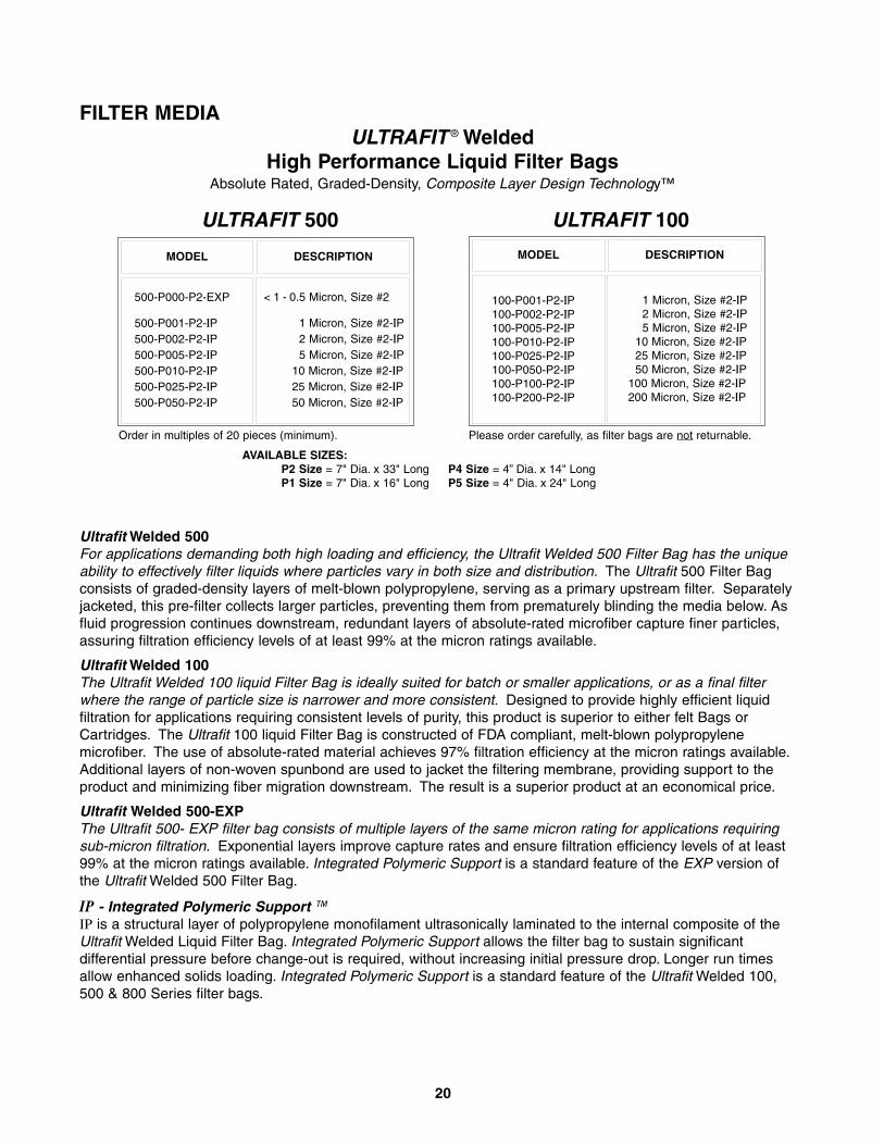
Ultrafit Welded 500For applications demanding both high loading and efficiency, the Ultrafit Welded 500 Filter Bag has the uniqueability to effectively filter liquids where particles vary in both size and distribution. The Ultrafit 500 Filter Bagconsists of graded-density layers of melt-blown polypropylene, serving as a primary upstream filter. Separatelyjacketed, this pre-filter collects larger particles, preventing them from prematurely blinding the media below. Asfluid progression continues downstream, redundant layers of absolute-rated microfiber capture finer particles,assuring filtration efficiency levels of at least 99% at the micron ratings available.
Ultrafit Welded 100 The Ultrafit Welded 100 liquid Filter Bag is ideally suited for batch or smaller applications, or as a final filterwhere the range of particle size is narrower and more consistent. Designed to provide highly efficient liquidfiltration for applications requiring consistent levels of purity, this product is superior to either felt Bags orCartridges. The Ultrafit 100 liquid Filter Bag is constructed of FDA compliant, melt-blown polypropylenemicrofiber. The use of absolute-rated material achieves 97% filtration efficiency at the micron ratings available.Additional layers of non-woven spunbond are used to jacket the filtering membrane, providing support to theproduct and minimizing fiber migration downstream. The result is a superior product at an economical price.
Ultrafit Welded 500-EXP The Ultrafit 500- EXP filter bag consists of multiple layers of the same micron rating for applications requiringsub-micron filtration. Exponential layers improve capture rates and ensure filtration efficiency levels of at least99% at the micron ratings available. Integrated Polymeric Support is a standard feature of the EXP version of the Ultrafit Welded 500 Filter Bag.
IP - Integrated Polymeric Support ™IP is a structural layer of polypropylene monofilament ultrasonically laminated to the internal composite of theUltrafit Welded Liquid Filter Bag. Integrated Polymeric Support allows the filter bag to sustain significantdifferential pressure before change-out is required, without increasing initial pressure drop. Longer run timesallow enhanced solids loading. Integrated Polymeric Support is a standard feature of the Ultrafit Welded 100,500 & 800 Series filter bags.
MODEL DESCRIPTION
FILTER MEDIAULTRAFIT ® Welded
High Performance Liquid Filter BagsAbsolute Rated, Graded-Density, Composite Layer Design Technology™
500-P000-P2-EXP
500-P001-P2-IP500-P002-P2-IP500-P005-P2-IP500-P010-P2-IP500-P025-P2-IP500-P050-P2-IP
< 1 - 0.5 Micron, Size #2
1 Micron, Size #2-IP2 Micron, Size #2-IP5 Micron, Size #2-IP
10 Micron, Size #2-IP25 Micron, Size #2-IP50 Micron, Size #2-IP
ULTRAFIT 500
100-P001-P2-IP100-P002-P2-IP100-P005-P2-IP100-P010-P2-IP100-P025-P2-IP100-P050-P2-IP100-P100-P2-IP100-P200-P2-IP
1 Micron, Size #2-IP2 Micron, Size #2-IP5 Micron, Size #2-IP
10 Micron, Size #2-IP25 Micron, Size #2-IP50 Micron, Size #2-IP
100 Micron, Size #2-IP200 Micron, Size #2-IP
ULTRAFIT 100
Order in multiples of 20 pieces (minimum).
MODEL DESCRIPTION
Please order carefully, as filter bags are not returnable.
AVAILABLE SIZES:P2 Size = 7" Dia. x 33" Long P4 Size = 4” Dia. x 14" LongP1 Size = 7" Dia. x 16" Long P5 Size = 4" Dia. x 24" Long
20
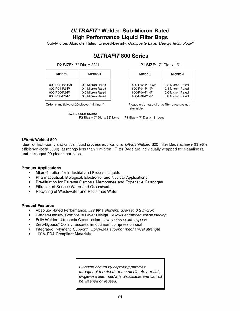
MODEL MICRON
ULTRAFIT ® Welded Sub-Micron RatedHigh Performance Liquid Filter Bags
Sub-Micron, Absolute Rated, Graded-Density, Composite Layer Design Technology™
MODEL MICRON
800-P02-P2-EXP800-P04-P2-IP 800-P06-P2-IP800-P08-P2-IP
0.2 Micron Rated0.4 Micron Rated0.6 Micron Rated0.8 Micron Rated
P2 SIZE: 7" Dia. x 33" L
800-P02-P1-EXP800-P04-P1-IP 800-P06-P1-IP800-P08-P1-IP
0.2 Micron Rated0.4 Micron Rated0.6 Micron Rated0.8 Micron Rated
P1 SIZE: 7" Dia. x 16" L
Ultrafit Welded 800Ideal for high-purity and critical liquid process applications, Ultrafit Welded 800 Filter Bags achieve 99.98%efficiency (beta 5000), at ratings less than 1 micron. Filter Bags are individually wrapped for cleanliness, and packaged 20 pieces per case.
Product Applications• Micro-filtration for Industrial and Process Liquids • Pharmaceutical, Biological, Electronic, and Nuclear Applications • Pre-filtration for Reverse Osmosis Membranes and Expensive Cartridges• Filtration of Surface Water and Groundwater • Recycling of Wastewater and Reclaimed Water
Product Features• Absolute Rated Performance…99.98% efficient, down to 0.2 micron• Graded-Density, Composite Layer Design…allows enhanced solids loading• Fully Welded Ultrasonic Construction…eliminates solids bypass• Zero-Bypass® Collar…assures an optimum compression seal• Integrated Polymeric Support® …provides superior mechanical strength• 100% FDA Compliant Materials
ULTRAFIT 800 Series
Order in multiples of 20 pieces (minimum). Please order carefully, as filter bags are notreturnable.
AVAILABLE SIZES:P2 Size = 7" Dia. x 33" Long P1 Size = 7" Dia. x 16" Long
21
Filtration occurs by capturing particlesthroughout the depth of the media. As a result,single-use filter media is disposable and cannotbe washed or reused.
22
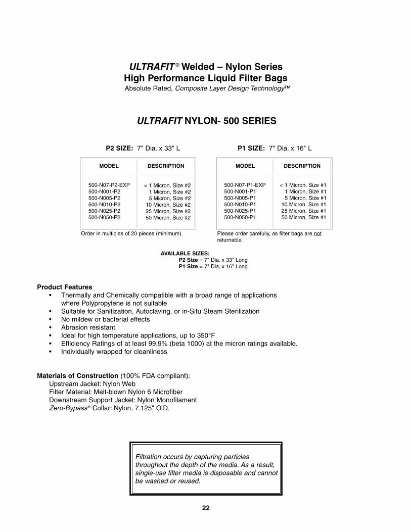
ULTRAFIT ® Welded – Nylon SeriesHigh Performance Liquid Filter BagsAbsolute Rated, Composite Layer Design Technology™
Product Features• Thermally and Chemically compatible with a broad range of applications
where Polypropylene is not suitable• Suitable for Sanitization, Autoclaving, or in-Situ Steam Sterilization• No mildew or bacterial effects• Abrasion resistant• Ideal for high temperature applications, up to 350°F• Efficiency Ratings of at least 99.9% (beta 1000) at the micron ratings available.• Individually wrapped for cleanliness
Materials of Construction (100% FDA compliant):Upstream Jacket: Nylon Web Filter Material: Melt-blown Nylon 6 Microfiber Downstream Support Jacket: Nylon MonofilamentZero-Bypass ® Collar: Nylon, 7.125" O.D.
ULTRAFIT NYLON- 500 SERIES
MODEL DESCRIPTION
500-N07-P2-EXP500-N001-P2500-N005-P2500-N010-P2500-N025-P2500-N050-P2
< 1 Micron, Size #21 Micron, Size #25 Micron, Size #2
10 Micron, Size #225 Micron, Size #250 Micron, Size #2
MODEL DESCRIPTION
P2 SIZE: 7" Dia. x 33" L
500-N07-P1-EXP500-N001-P1500-N005-P1500-N010-P1500-N025-P1500-N050-P1
< 1 Micron, Size #11 Micron, Size #15 Micron, Size #1
10 Micron, Size #125 Micron, Size #150 Micron, Size #1
P1 SIZE: 7" Dia. x 16" L
Order in multiples of 20 pieces (minimum). Please order carefully, as filter bags are notreturnable.
AVAILABLE SIZES:P2 Size = 7" Dia. x 33" LongP1 Size = 7" Dia. x 16" Long
Filtration occurs by capturing particlesthroughout the depth of the media. As a result,single-use filter media is disposable and cannotbe washed or reused.
23
ULTRAFIT ® Welded – AMT ™ SeriesAntimicrobial Technology (AMT) High Performance Liquid Filter Bags
MODEL DESCRIPTION
AMT-P04-P2-IPAMT-P06-P2-IPAMT-P08-P2-IP
AMT-P001-P2-IPAMT-P003-P2-IPAMT-P005-P2-IP
0.4 Micron, Size #20.6 Micron, Size #20.8 Micron, Size #2
1 Micron, Size #23 Micron, Size #25 Micron, Size #2
MODEL DESCRIPTION
AMT-P04-P1-IPAMT-P06-P1-IPAMT-P08-P1-IP
AMT-P001-P1-IPAMT-P003-P1-IPAMT-P005-P1-IP
0.4 Micron, Size #10.6 Micron, Size #10.8 Micron, Size #1
1 Micron, Size #13 Micron, Size #15 Micron, Size #1
P2 SIZE: 7" Dia. x 33" L P1 SIZE: 7" Dia. x 16" L
Please order carefully, as filter bags are notreturnable.
Standard Features and Materials of Construction• Multi-Layer, High Performance Liquid Filter Bag• Graded Density, Composite Layer Design Technology™• Antimicrobial Agent incorporated into the final filtering layers of the Bag• 99.98% efficiency ratings (beta 5000)• Materials of construction: 100% FDA Compliant Polypropylene• Single-use, disposable Filter Bag
Benefits of Antimicrobial Technology• Antimicrobial agent inhibits the growth of broad spectrum bacteria,
fungi, protozoa, and yeast on the treated layers• Antimicrobial agent lasts the life of the filter• Non-Toxic and insoluble in water
What are some uses for Ultrafit Welded-AMT Series High Performance Filter Bags?When properly installed in a Filtration Systems Over-The-Top® design housing, Ultrafit Welded-AMT Series filter bags areuseful in filtering many types of liquids, including water, transformer cooling oil, synthetic oil, lubricants, paints, and otherwater-based liquids, when prevention of fluid contamination during the filtering process is important to the final product.
Why is Antimicrobial Protection important for my filtering process?Microorganisms can contaminate liquids causing spoilage, odor, degradation, and reduced shelf life of products. Othereffects of contamination may include changes in viscosity or pH, discoloration, gassing during processing, or swelling offinished product containers. During the filtering process the formation of biofilms may inhibit liquid flow, contaminate orcorrode process piping, and affect heat exchange.
How does Antimicrobial Technology work?Antimicrobial additives disrupt the metabolic function of thin walled, aerobic and anaerobic microorganisms, inhibitingtheir ability to function, grow, and reproduce on the filter media.
How is the Antimicrobial agent built into the media?The antimicrobial agent is incorporated into the polymeric voids of the polypropylene fiber, without affecting the physicalproperties of the fiber. The submicron-sized particles migrate to the surface of the fiber, where they become an integralpart of the microfiber. Since it is part of the fiber, not a surface coating, it will not wash or wear out. The antimicrobialagent is insoluble in water and lasts the life of the filter.
Is it safe?Antimicrobial agents only attack thin-walled cells. Human and animal cells are thick-walled, and are thereforeimpermeable to the antibacterial additive. The antimicrobial agent, Triclosan (Chlorinated Phenoxy Compound), isregistered with the EPA as a safe, non-toxic product.
NOTE: The Ultrafit Welded- AMT Filter Bag does not protect users or others against food-borne (or disease causing) bacteria.Mechanical Manufacturing Corporation, Filtration Systems Division is not making any health claims for this product.
Order in multiples of 20 pieces (minimum).
AVAILABLE SIZES:P2 Size = 7" Dia. x 33" Long P4 Size = 4” Dia. x 14" LongP1 Size = 7" Dia. x 16" Long P5 Size = 4" Dia. x 24" Long
24
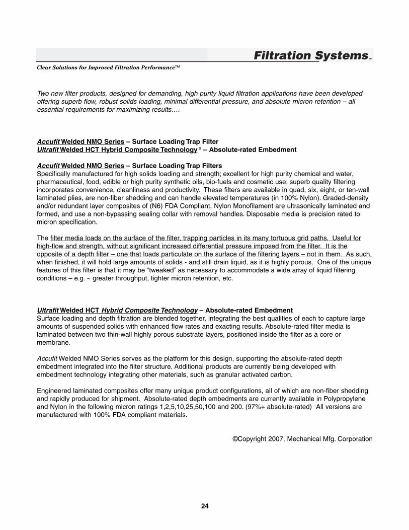
Two new filter products, designed for demanding, high purity liquid filtration applications have been developedoffering superb flow, robust solids loading, minimal differential pressure, and absolute micron retention – allessential requirements for maximizing results….
Accufit Welded NMO Series – Surface Loading Trap FilterUltrafit Welded HCT Hybrid Composite Technology ® – Absolute-rated Embedment
Accufit Welded NMO Series – Surface Loading Trap FiltersSpecifically manufactured for high solids loading and strength; excellent for high purity chemical and water,pharmaceutical, food, edible or high purity synthetic oils, bio-fuels and cosmetic use; superb quality filteringincorporates convenience, cleanliness and productivity. These filters are available in quad, six, eight, or ten-walllaminated plies, are non-fiber shedding and can handle elevated temperatures (in 100% Nylon). Graded-densityand/or redundant layer composites of (N6) FDA Compliant, Nylon Monofilament are ultrasonically laminated andformed, and use a non-bypassing sealing collar with removal handles. Disposable media is precision rated tomicron specification.
The filter media loads on the surface of the filter, trapping particles in its many tortuous grid paths. Useful forhigh-flow and strength, without significant increased differential pressure imposed from the filter. It is theopposite of a depth filter – one that loads particulate on the surface of the filtering layers – not in them. As such,when finished, it will hold large amounts of solids - and still drain liquid, as it is highly porous. One of the uniquefeatures of this filter is that it may be “tweaked” as necessary to accommodate a wide array of liquid filteringconditions – e.g. ~ greater throughput, tighter micron retention, etc.
Ultrafit Welded HCT Hybrid Composite Technology – Absolute-rated EmbedmentSurface loading and depth filtration are blended together, integrating the best qualities of each to capture largeamounts of suspended solids with enhanced flow rates and exacting results. Absolute-rated filter media islaminated between two thin-wall highly porous substrate layers, positioned inside the filter as a core ormembrane.
Accufit Welded NMO Series serves as the platform for this design, supporting the absolute-rated depthembedment integrated into the filter structure. Additional products are currently being developed withembedment technology integrating other materials, such as granular activated carbon.
Engineered laminated composites offer many unique product configurations, all of which are non-fiber sheddingand rapidly produced for shipment. Absolute-rated depth embedments are currently available in Polypropyleneand Nylon in the following micron ratings 1,2,5,10,25,50,100 and 200. (97%+ absolute-rated) All versions aremanufactured with 100% FDA compliant materials.
©Copyright 2007, Mechanical Mfg. Corporation
Clear Solutions for Improved Filtration Performance™
MODEL DESCRIPTIONMODEL DESCRIPTION
MODEL DESCRIPTIONMODEL DESCRIPTION
P-001-P2-IPP-005-P2-IPP-010-P2-IPP-025-P2-IPP-050-P2-IPP-100-P2-IPP-200-P2-IP
1 Micron, Size #2-IP5 Micron, Size #2-IP
10 Micron, Size #2-IP25 Micron, Size #2-IP50 Micron, Size #2-IP
100 Micron, Size #2-IP200 Micron, Size #2-IP
P2 SIZE: 7" Dia. x 33" L
P-001-P1-IPP-005-P1-IPP-010-P1-IPP-025-P1-IPP-050-P1-IPP-100-P1-IP P-200-P1-IP
1 Micron, Size #1-IP5 Micron, Size #1-IP
10 Micron, Size #1-IP25 Micron, Size #1-IP50 Micron, Size #1-IP
100 Micron, Size #1-IP200 Micron, Size #1-IP
P1 SIZE: 7" Dia. x 16" L
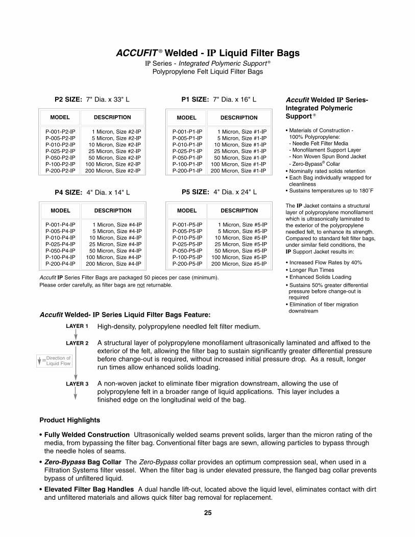
ACCUFIT ® Welded - IP Liquid Filter BagsIP Series - Integrated Polymeric Support ®
Polypropylene Felt Liquid Filter Bags
P-001-P4-IPP-005-P4-IPP-010-P4-IPP-025-P4-IPP-050-P4-IPP-100-P4-IPP-200-P4-IP
1 Micron, Size #4-IP5 Micron, Size #4-IP
10 Micron, Size #4-IP25 Micron, Size #4-IP50 Micron, Size #4-IP
100 Micron, Size #4-IP200 Micron, Size #4-IP
P4 SIZE: 4" Dia. x 14" L
P-001-P5-IPP-005-P5-IPP-010-P5-IPP-025-P5-IPP-050-P5-IPP-100-P5-IPP-200-P5-IP
1 Micron, Size #5-IP5 Micron, Size #5-IP
10 Micron, Size #5-IP25 Micron, Size #5-IP50 Micron, Size #5-IP
100 Micron, Size #5-IP200 Micron, Size #5-IP
P5 SIZE: 4" Dia. x 24" L
Accufit Welded IP Series-Integrated PolymericSupport ®
• Materials of Construction -100% Polypropylene:- Needle Felt Filter Media- Monofilament Support Layer- Non Woven Spun Bond Jacket- Zero-Bypass® Collar
• Nominally rated solids retention• Each Bag individually wrapped for
cleanliness• Sustains temperatures up to 180˚F
The IP Jacket contains a structurallayer of polypropylene monofilamentwhich is ultrasonically laminated tothe exterior of the polypropyleneneedled felt, to enhance its strength.Compared to standard felt filter bags,under similar field conditions, theIP Support Jacket results in:
• Increased Flow Rates by 40%• Longer Run Times• Enhanced Solids Loading
• Sustains 50% greater differentialpressure before change-out isrequired
• Elimination of fiber migrationdownstream
Accufit IP Series Filter Bags are packaged 50 pieces per case (minimum).Please order carefully, as filter bags are not returnable.
25
Accufit Welded- IP Series Liquid Filter Bags Feature:
High-density, polypropylene needled felt filter medium.
A structural layer of polypropylene monofilament ultrasonically laminated and affixed to theexterior of the felt, allowing the filter bag to sustain significantly greater differential pressurebefore change-out is required, without increased initial pressure drop. As a result, longerrun times allow enhanced solids loading.
A non-woven jacket to eliminate fiber migration downstream, allowing the use ofpolypropylene felt in a broader range of liquid applications. This layer includes afinished edge on the longitudinal weld of the bag.
Product Highlights
• Fully Welded Construction Ultrasonically welded seams prevent solids, larger than the micron rating of themedia, from bypassing the filter bag. Conventional filter bags are sewn, allowing particles to bypass throughthe needle holes of seams.
• Zero-Bypass Bag Collar The Zero-Bypass collar provides an optimum compression seal, when used in aFiltration Systems filter vessel. When the filter bag is under elevated pressure, the flanged bag collar preventsbypass of unfiltered liquid.
• Elevated Filter Bag Handles A dual handle lift-out, located above the liquid level, eliminates contact with dirtand unfiltered materials and allows quick filter bag removal for replacement.
LAYER 1
LAYER 2
LAYER 3
Direction ofLiquid Flow
=
26
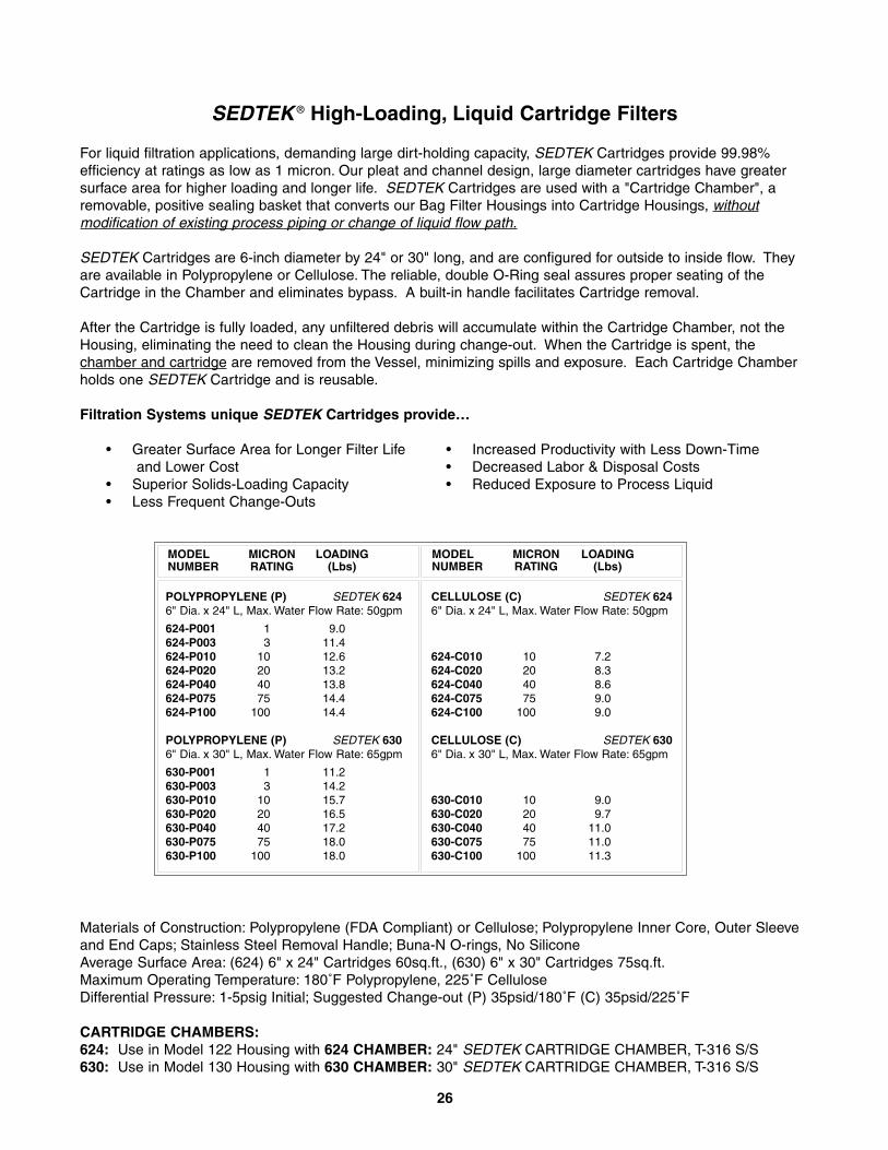
SEDTEK ® High-Loading, Liquid Cartridge Filters
For liquid filtration applications, demanding large dirt-holding capacity, SEDTEK Cartridges provide 99.98%efficiency at ratings as low as 1 micron. Our pleat and channel design, large diameter cartridges have greatersurface area for higher loading and longer life. SEDTEK Cartridges are used with a "Cartridge Chamber", aremovable, positive sealing basket that converts our Bag Filter Housings into Cartridge Housings, withoutmodification of existing process piping or change of liquid flow path.
SEDTEK Cartridges are 6-inch diameter by 24" or 30" long, and are configured for outside to inside flow. Theyare available in Polypropylene or Cellulose. The reliable, double O-Ring seal assures proper seating of theCartridge in the Chamber and eliminates bypass. A built-in handle facilitates Cartridge removal.
After the Cartridge is fully loaded, any unfiltered debris will accumulate within the Cartridge Chamber, not theHousing, eliminating the need to clean the Housing during change-out. When the Cartridge is spent, thechamber and cartridge are removed from the Vessel, minimizing spills and exposure. Each Cartridge Chamberholds one SEDTEK Cartridge and is reusable.
Filtration Systems unique SEDTEK Cartridges provide…
• Greater Surface Area for Longer Filter Life • Increased Productivity with Less Down-Time and Lower Cost • Decreased Labor & Disposal Costs
• Superior Solids-Loading Capacity • Reduced Exposure to Process Liquid • Less Frequent Change-Outs
MODEL MICRON LOADINGNUMBER RATING (Lbs)
POLYPROPYLENE (P) SEDTEK 6246" Dia. x 24" L, Max. Water Flow Rate: 50gpm
624-P001 1 9.0624-P003 3 11.4 624-P010 10 12.6624-P020 20 13.2 624-P040 40 13.8624-P075 75 14.4624-P100 100 14.4
POLYPROPYLENE (P) SEDTEK 6306" Dia. x 30" L, Max. Water Flow Rate: 65gpm
630-P001 1 11.2 630-P003 3 14.2 630-P010 10 15.7630-P020 20 16.5630-P040 40 17.2630-P075 75 18.0630-P100 100 18.0
Materials of Construction: Polypropylene (FDA Compliant) or Cellulose; Polypropylene Inner Core, Outer Sleeveand End Caps; Stainless Steel Removal Handle; Buna-N O-rings, No Silicone Average Surface Area: (624) 6" x 24" Cartridges 60sq.ft., (630) 6" x 30" Cartridges 75sq.ft.Maximum Operating Temperature: 180˚F Polypropylene, 225˚F Cellulose Differential Pressure: 1-5psig Initial; Suggested Change-out (P) 35psid/180˚F (C) 35psid/225˚F
CARTRIDGE CHAMBERS:624: Use in Model 122 Housing with 624 CHAMBER: 24" SEDTEK CARTRIDGE CHAMBER, T-316 S/S630: Use in Model 130 Housing with 630 CHAMBER: 30" SEDTEK CARTRIDGE CHAMBER, T-316 S/S
MODEL MICRON LOADINGNUMBER RATING (Lbs)
CELLULOSE (C) SEDTEK 6246" Dia. x 24" L, Max. Water Flow Rate: 50gpm
624-C010 10 7.2624-C020 20 8.3624-C040 40 8.6624-C075 75 9.0624-C100 100 9.0
CELLULOSE (C) SEDTEK 6306" Dia. x 30" L, Max. Water Flow Rate: 65gpm
630-C010 10 9.0630-C020 20 9.7630-C040 40 11.0630-C075 75 11.0630-C100 100 11.3
27
STANDARD TERMS & CONDITIONS OF SALE
DOMESTIC PAYMENT TERMSOpen Account Terms are NET 30 DAYS, after credit approval. Until credit has been established, termsare payment by credit card, or advance payment. We accept Master Card, VISA, and American Express.Accounts are considered delinquent 30 days after due date, and are subject to suspension and collection. If thisshould occur, the buyer will be responsible for all collection costs, filing fees, and attorney’s fees. Venue for suchaction shall be in Broward County, Florida. Filtration Systems reserves the right to limit or extend credit.
All pricing is in U.S. Dollars, payable in U.S. Funds on a U.S. bank. Sales and shipments within the State ofFlorida will be subject to Florida Sales Tax. A valid Certificate of Resale must be furnished if no sales tax is tobe collected.
INTERNATIONAL SALES AND TERMSOrders from outside the United States must be paid IN ADVANCE by Credit Card or T/T Wire. IrrevocableLetters of Credit (L/C) are not accepted. Export order processing or production will commence upon receipt offunds. All shipping arrangements should be made by the buyer, and orders will be shipped FREIGHT COLLECT,via buyer’s Freight Forwarder.There is a $50.00 processing fee for export orders (one per shipment). All duties, taxes, documentation,and bank charges are the responsibility of the buyer.
ORDER/SHIPMENT POLICIESAll Purchase Orders must be faxed or mailed to Filtration Systems before order will be shipped.With over 30 years of industry expertise and proven performance, Filtration Systems offers quality products atresponsible prices. We continually strive to improve our products through ongoing research and development;therefore, we reserve the right to change specifications without notice.
MINIMUM ORDER REQUIREMENTS1. Minimum order for filter bags is one case (see price sheet for case quantities).2. For all other items, minimum order is $75.00.
CUSTOM ORDERSPlease consult factory for custom items and/or modifications. Payment for custom items or modifiedequipment may be required prior to fabrication.CUSTOM ITEMS OR MODIFIED EQUIPMENT ARE NOT RETURNABLE.
FREIGHT TERMSAll shipments are FOB Plant, Sunrise, Florida, USA. All shipping charges are the responsibility of thebuyer. Filtration Systems will NOT prepay airfreight charges. Air shipments will be sent FREIGHTCOLLECT. Please provide account number (FedEx, UPS, etc.) to bill charges. Orders can be drop shippedwithin the Continental United States only.
MERCHANDISE RETURNSFilter Bags, Cartridge Filters, Baskets, O-Rings, HALAR Coated Vessels and Accessories, Epoxy CoatedVessels, and Custom Items or Modified Equipment are NOT returnable.
Authorization and the issuance of an RGA Number (Return Goods Authorization Number) MUST be obtainedbefore returning any merchandise. Returned goods are to be shipped freight prepaid and are subject to a30% restocking charge. Outside of carton MUST be labeled with our RGA number. Any item returned withoutan RGA number or sent with incorrect freight classification number will be refused.
28
WARRANTY / LIMITATION OF LIABILITY
WarrantyFiltration Systems warrants its products to be free from defects in workmanship for a period of one year from thedate of purchase, when used in accordance with our specific guidelines. Our only obligation and a customer’sremedy, subject to our inspection and evaluation, shall be to replace the product or refund the purchase price.
Limitation of LiabilityFiltration Systems shall not be held responsible or liable for any loss resulting from the resale, direct or indirectmisuse, incidental or consequential damages, arising out of the use of this product. Not all questions or issuesmay have been addressed in this manual. If you require any additional assistance or technical information,please contact our Customer Service Department.
Lethal ServiceFiltration Systems vessels are not designed for lethal service. "Lethal Service" refers to vessels containing lethal substances, poisonous gases or liquids of such a nature that a very small amount of the gas or vapor ofthe liquid (mixed or unmixed) is dangerous to life when inhaled. In addition, substances of this nature that arestored under pressure, or may generate pressure if stored in a closed vessel, are considered lethal.
Product IdentificationAll Filtration Systems filter vessels have a unique serial number that can be identified by our factory.Nameplates, specifying both the serial number and maximum allowable pressure and temperature rating arepermanently affixed to all housings.
PRODUCT SPECIFICATIONS / INTELLECTUAL PROPERTY
Product SpecificationsWith over 30 years of industry expertise and proven performance, Filtration Systems offers quality products atresponsible prices. We continually strive to improve our products through ongoing research and development;therefore, we reserve the right to change specifications without notice.
Intellectual PropertyFiltration Systems products offer exclusive manufacturing technology. Our company is committed to protecting its patents, trademarks, and proprietary rights from those who would wrongfully use them.
Partial Listing of Registered Trademarks of Mechanical Manufacturing Corporation…Over-The-Top ®
SAFEsystem ®
Ultrafit ® Welded Liquid Filter BagsAccufit ® Welded Liquid Filter BagsZero-Bypass ® CollarIP Integrated Polymeric Support ®
EXP ® SeriesBullet Bottom ® BasketSEDTEK ®
AMT -Antimicrobial Technology™
Composite Layer Design Technology™
Other Trademarks…Halar® is a registered Trademark of Solvay Solexis, Inc.Aflas® is a registered Trademark of Asahi Glass Co. Ltd.Neoprene®, Teflon®, and Viton® are Registered Trademarks of E.I. Dupont Company

® © 2007 Mechanical Manufacturing CorporationFS-IO/12-07