
Filtration for Ink Jet Ink Formulation...with a given ink chemistry and how it might impact printer...
12
www.pall.com Filtration for Ink Jet Ink Formulation Techniques for Evaluating Filtration in the Laboratory
Transcript of Filtration for Ink Jet Ink Formulation...with a given ink chemistry and how it might impact printer...
www.pall.com
Filtration for Ink Jet InkFormulation
Techniques for Evaluating Filtration in the Laboratory

2 www.pall.com
Why Pall
Established more than 60 years ago, Pall Corporation
has grown to be the largest and most diverse filtration,
separations, and purification company in the world.
Our global presence is far-reaching, and our product
portfolio and technical expertise are extensive.
Pall offers a variety of filtration products and services
to help you improve efficiency and results in the lab.
Our staff scientists and engineers provide services and
conduct research and development, with intensive,
broad-based assistance from Pall’s worldwide
technical support network. Our experts work directly
with you to determine how Pall products and
technologies can benefit you.
www.pall.com 3
4 www.pall.com
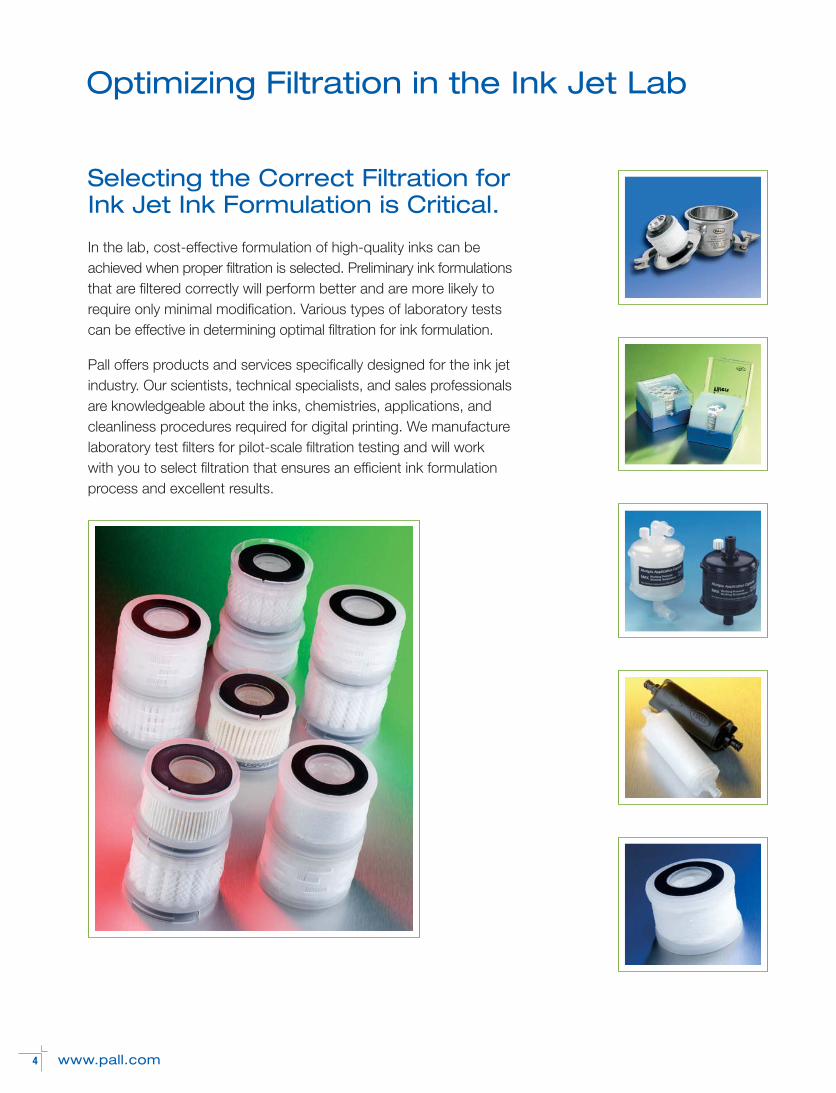
In the lab, cost-effective formulation of high-quality inks can beachieved when proper filtration is selected. Preliminary ink formulationsthat are filtered correctly will perform better and are more likely torequire only minimal modification. Various types of laboratory testscan be effective in determining optimal filtration for ink formulation.
Pall offers products and services specifically designed for the ink jet industry. Our scientists, technical specialists, and sales professionalsare knowledgeable about the inks, chemistries, applications, andcleanliness procedures required for digital printing. We manufacturelaboratory test filters for pilot-scale filtration testing and will work with you to select filtration that ensures an efficient ink formulationprocess and excellent results.
Optimizing Filtration in the Ink Jet Lab
Selecting the Correct Filtration forInk Jet Ink Formulation is Critical.
There are several types of laboratory tests that can beused to determine optimal filtration for ink formulationand for use on-board printers. The tests describedbelow are the most frequently recommended and the most commonly used. (Note: Specific testingprocedures for filterability and ink cleanliness can befound on pages 6-9.)
Test filters are used for filterability and other types of testing. They are fabricated of the same filter mediaand have the same structure as their full-size counterparts, but are much smaller in scale. Datagathered from test filter studies can be extrapolatedto the full-scale process. In addition, the quality ofthe effluent produced will be representative of thequality expected when using a full-size filter.
Filterability testing
Filterability testing during pilot-scale manufacturingwill help determine filter usage and allow optimizationof the entire filtration process. It is a tool by whichthe ink jet ink formulator can maximize filter perform-ance and filtration economics while maintaining consistent ink quality.
Filterability testing can provide answers to these andother questions about ink jet ink filtration.
■ Do I need a prefilter?
■ How much will it cost (per liter) to filter this ink?
■ What is the best flow rate?
■ When do I change filters?
■ How do I prevent gel breakthrough?
A specifically designed apparatus is needed to conduct the testing. In addition to generating valuable analytical data, the rig can be used to produce ink samples for customer testing. (Note: A list of equipment and instructions for setting up the test rig are provided on page 6.)
Filter and ink compatibility testing
As ink with aggressive chemistries becomes more prevalent, testing for filter and ink compatibility hasbecome critical to the ink development process.Though compatibility is a complex issue, the real-time test experience improves one’s understanding of a particular filter’s compatibility with a given ink chemistry and how it might impactprinter performance.
Printhead performance testing
Tests can be conducted to determine how filtrationduring ink formulation will impact the long-term performance of an ink jet printhead. Small filter discsare used to facilitate laboratory testing with smallsample volumes. These discs are generally availablein the same variety of media as full-size filters.
Ink cleanliness quality testing
Real-time ink quality checks are an integral part ofthe ink jet ink formulation process. A robust qualitycontrol process ensures that ink production hasconformed to quality requirements and that a qualityproduct will be shipped to the customer.
www.pall.com 5
Techniques for Evaluating Filtration forInk Formulation
NOTES:
6 www.pall.com
Filterability Testing Procedures
Filterability testing consists of taking differential pressure measurements while passing fluid through a small test filter at a constant flow rate.
The following information is provided to ensure the accuracy of your test results.
■ List of required equipment
■ Procedure for performing testing and data collection
■ Instructions for setting up the equipment
■ Method for analyzing the data
Equipment checklist
The equipment listed below is required to build the filterability test rig.
• Laboratory test filter. Small-scale version of full-size filter with identical design, construction,and media.
• Filter housing. Small stainless steel filter housingfor the laboratory test filter.
• Vent valve. Ball valve (or similar), installed on theupstream side of the filter housing, that allowstrapped air to be vented.
• Pressure gauges. Pressure gauges, installed onthe filter housing, on the inlet and outlet ports ofthe filter. If the outlet discharges to atmosphericpressure, the outlet pressure gauge is notrequired. Recommended pressure range is 0-30psig/2.07 barg.
• Pump. Small laboratory pump capable of flowrates from 0.1-2 lpm. A peristaltic pump is mostcommonly used.
• Tubing. Tubing that is compatible with the inkchemistry and pump type.
• Reservoirs. Vessels that feed to the pump andreceive filtered fluid from the filter housing.
• Other. Glassware (for volumetric measurement),mixing apparatus (for unstable dispersions), stopwatch (for accurate time measurement), various fittings and hand tools.
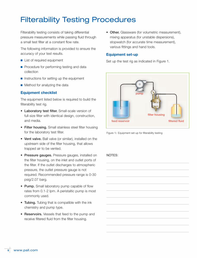
Equipment set-up
Set up the test rig as indicated in Figure 1.
feed reservoir filtered fluid
pump
filter housing
Figure 1: Equipment set-up for filterability testing
NOTES:
www.pall.com 7
Testing and data collection
To perform filterability testing and plot the dataretrieved, follow the steps below.
1. Install a new filter, with gaskets, into the filterhousing.
2. Open the vent valve to allow air to purge from the system.
3. Turn on the pump to start the flow; allow ink to fill the tubing and housing.
4. As soon as ink starts flowing from the vent, closethe vent valve and start the stopwatch.
5. When ink starts flowing from the filter outlet tubing,record the clean differential pressure value.
6. Using volumetric glassware, measure the flowrate and record the value.
7. Continue to record differential pressure values atset time intervals.
8. Once the filter has achieved maximum differential pressure (usually 25 psid/1.70 bard), turn off thepump and allow the system pressure to subside.
9. Remove and discard the filter; clean the housingand equipment.
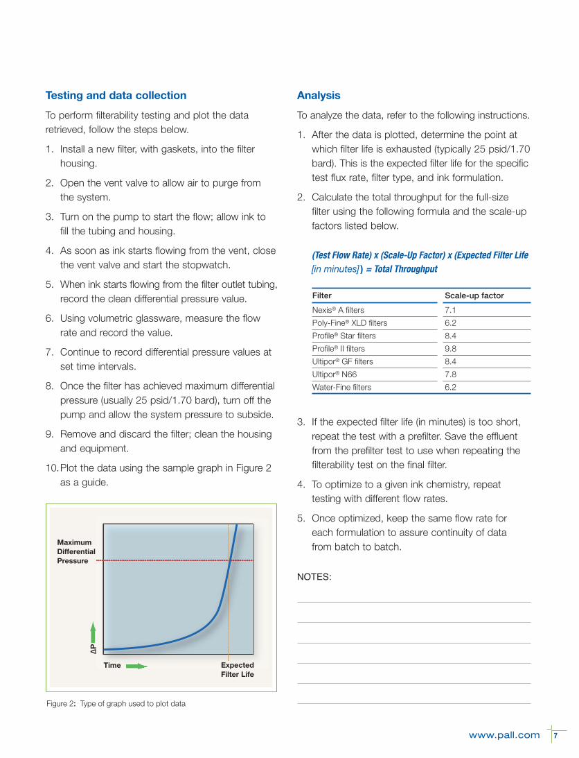
10.Plot the data using the sample graph in Figure 2as a guide.
Analysis
To analyze the data, refer to the following instructions.
1. After the data is plotted, determine the point atwhich filter life is exhausted (typically 25 psid/1.70bard). This is the expected filter life for the specifictest flux rate, filter type, and ink formulation.
2. Calculate the total throughput for the full-size filter using the following formula and the scale-upfactors listed below.
3. If the expected filter life (in minutes) is too short,repeat the test with a prefilter. Save the effluentfrom the prefilter test to use when repeating thefilterability test on the final filter.
4. To optimize to a given ink chemistry, repeat testing with different flow rates.
5. Once optimized, keep the same flow rate foreach formulation to assure continuity of datafrom batch to batch.Maximum
DifferentialPressure
ExpectedFilter Life
Time
ΔP
Figure 2: Type of graph used to plot data
(Test Flow Rate) x (Scale-Up Factor) x (Expected Filter Life [in minutes] ) = Total Throughput
Filter Scale-up factor
Nexis® A filters 7.1
Poly-Fine® XLD filters 6.2
Profile® Star filters 8.4
Profile® II filters 9.8
Ultipor® GF filters 8.4
Ultipor® N66 7.8
Water-Fine filters 6.2
NOTES:
8 www.pall.com
Ink Cleanliness Quality Testing Procedures
Ink cleanliness quality testing involves determiningthe cleanliness factor of an ink sample. The cleanliness factor is defined as the ratio of membraneplugging between two distinct intervals. Since cleanliness factors vary depending on ink type, youwill need to correlate the resulting cleanliness factorback to printer performance.
The following information is provided to guide youthrough the testing process.
■ Instructions for setting up the equipment
■ Procedure for performing testing and data collection
■ Process for troubleshooting
Equipment checklist
The equipment listed below is required to conductink cleanliness quality testing.
• Vacuum flask. Flask must have a 1 liter minimumcapacity.
• Vacuum source with valve. Source must be able to maintain constant vacuum at 200 torr orgreater.
• Filter disc holder and funnel. To start with, aholder that can accommodate a 47 mm-diameterdisc and a glass funnel with a capacity of at least100 ml.
• Analysis filter discs. For dye-based inks, PallUltipor N66 disc filters rated at 0.45 µm; for pigmented inks, Pall Ultipor GF Plus disc filtersrated at 1 µm.
• Other. Tubing (for vacuum connection), glassware(for volumetric measurement), stopwatch (foraccurate time measurement), clean sample containers.
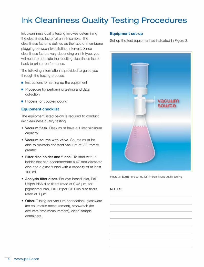
Equipment set-up
Set up the test equipment as indicated in Figure 3.
vacuumsource
Figure 3: Equipment set-up for ink cleanliness quality testing
NOTES:
www.pall.com 9
Testing and data collection
To perform ink cleanliness testing and chart the dataretrieved, follow the steps below.
1. Install analysis filter disc in the filter holder.
2. From the same ink batch, measure out threesamples of equal size. (A 100 ml sample is recommended to start.)
3. Start the vacuum source; pour the sample intothe funnel.
4. Open the vacuum source valve while simultaneously starting the stopwatch.
5. As soon as the sample has passed through the analysis membrane, stop the stopwatch, close thevacuum source valve, and record the time ( ti ).
6. Repeat the procedure for the second sample, butdo not record the time.
7. Repeat the procedure for the third sample, andrecord the time ( tf ).
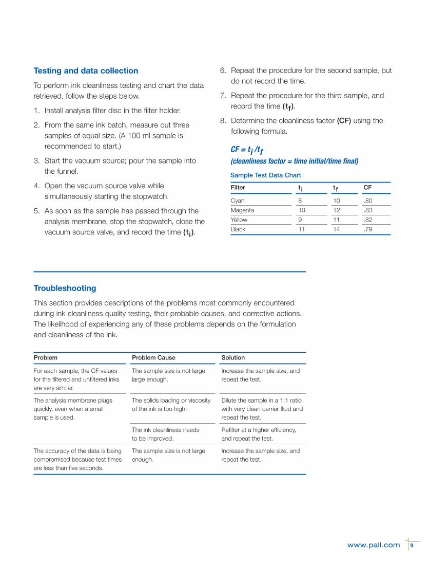
8. Determine the cleanliness factor (CF) using the following formula.
Troubleshooting
This section provides descriptions of the problems most commonly encounteredduring ink cleanliness quality testing, their probable causes, and corrective actions.The likelihood of experiencing any of these problems depends on the formulationand cleanliness of the ink.
CF = ti /tf(cleanliness factor = time initial/time final)
Sample Test Data Chart
Filter t i t f CF
Cyan 8 10 .80
Magenta 10 12 .83
Yellow 9 11 .82
Black 11 14 .79
Problem Problem Cause Solution
For each sample, the CF values The sample size is not large Increase the sample size, andfor the filtered and unfiltered inks large enough. repeat the test.are very similar.
The analysis membrane plugs The solids loading or viscosity Dilute the sample in a 1:1 ratioquickly, even when a small of the ink is too high. with very clean carrier fluid andsample is used. repeat the test.
The ink cleanliness needs Refilter at a higher efficiency, to be improved. and repeat the test.
The accuracy of the data is being The sample size is not large Increase the sample size, andcompromised because test times enough. repeat the test.are less than five seconds.
10 www.pall.com
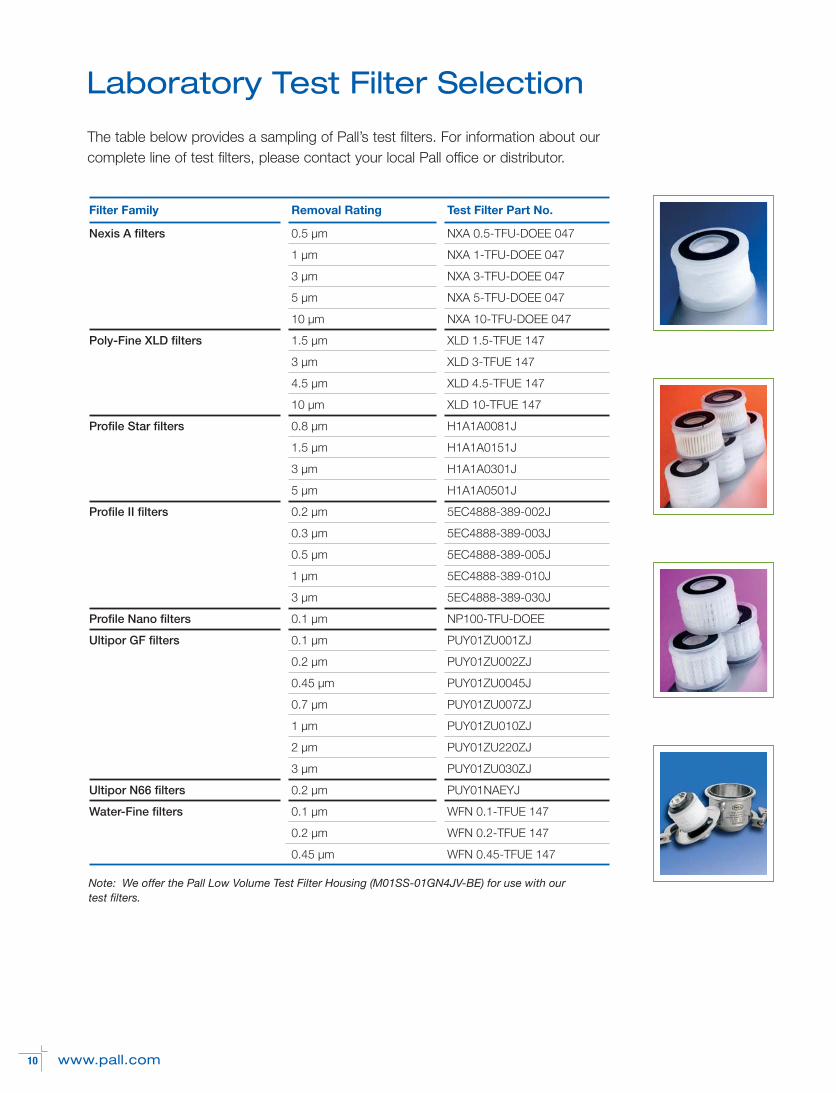
Laboratory Test Filter Selection
The table below provides a sampling of Pall’s test filters. For information about ourcomplete line of test filters, please contact your local Pall office or distributor.
Filter Family Removal Rating Test Filter Part No.
Nexis A filters 0.5 µm NXA 0.5-TFU-DOEE 047
1 µm NXA 1-TFU-DOEE 047
3 µm NXA 3-TFU-DOEE 047
5 µm NXA 5-TFU-DOEE 047
10 µm NXA 10-TFU-DOEE 047
Poly-Fine XLD filters 1.5 µm XLD 1.5-TFUE 147
3 µm XLD 3-TFUE 147
4.5 µm XLD 4.5-TFUE 147
10 µm XLD 10-TFUE 147
Profile Star filters 0.8 µm H1A1A0081J
1.5 µm H1A1A0151J
3 µm H1A1A0301J
5 µm H1A1A0501J
Profile II filters 0.2 µm 5EC4888-389-002J
0.3 µm 5EC4888-389-003J
0.5 µm 5EC4888-389-005J
1 µm 5EC4888-389-010J
3 µm 5EC4888-389-030J
Profile Nano filters 0.1 µm NP100-TFU-DOEE
Ultipor GF filters 0.1 µm PUY01ZU001ZJ
0.2 µm PUY01ZU002ZJ
0.45 µm PUY01ZU0045J
0.7 µm PUY01ZU007ZJ
1 µm PUY01ZU010ZJ
2 µm PUY01ZU220ZJ
3 µm PUY01ZU030ZJ
Ultipor N66 filters 0.2 µm PUY01NAEYJ
Water-Fine filters 0.1 µm WFN 0.1-TFUE 147
0.2 µm WFN 0.2-TFUE 147
0.45 µm WFN 0.45-TFUE 147
Note: We offer the Pall Low Volume Test Filter Housing (M01SS-01GN4JV-BE) for use with ourtest filters.

Pall Filtration Products for
Digital Printers
Pall has a wide range of filters that are designed with added features to accommodate ink jet printers. When used on-board digital printing systems, these filters provide maximum printhead protectionand excellent printer performance.
Please visit www.pall.com for more details.
Microelectronics25 Harbor Park DrivePort Washington, New York 11050+1 516 484 3600 telephone +1 800 360 7255 toll free US
Portsmouth - UK
+44 (0) 23 9233 8000 telephone+44 (0) 23 9233 8811 fax [email protected]
Visit us on the Web at www.pall.com
Pall Corporation has offices and plants throughout the world. For Pall representativesin your area, please go to www.pall.com/contact.
Because of technological developments related to the products, systems, and/orservices described herein, the data and procedures are subject to change withoutnotice. Please consult your Pall representative or visit www.pall.com to verify thatthis information remains valid.
© Copyright 2014 Pall Corporation. Pall, , Nexis, Poly-Fine, Profile and Ultipor aretrademarks of Pall Corporation. ® Indicates a Pall trademark registered in the USA. BETTER LIVES.BETTER PLANET. and Filtration. Separation. Solution.SM are service marks of Pall Corporation.
MEIJL06a January 2014
To see how Pall is helping enable a greener, safer and more sustainable future, visit www.pall.com/green.