
Filter structures - Aalto · Filter structures . Basic concepts ... ej2⇡!k/N Hk(z)=H...
24
Filter structures
Transcript of Filter structures - Aalto · Filter structures . Basic concepts ... ej2⇡!k/N Hk(z)=H...

Filter structures

Basic concepts
• Linear-phase FIR filters, types I-IV • Odd/even length, symmetrical/anti-symmetrical
• Group delay
• Magnitude response |H(ejω)|

Basic concepts
• Translation of filter’s pass-band • Modulation of filter coefficients
• Complementary filter G(z) = z-N/2 – H(z)
© R.W.
3

• Zero-phase/amplitude response • Impossible to implement in practice, but easy to implement when
causality is relaxed • Unlike magnitude response, can be negative
• Zero-phase response of symmetric even-order N (Type I) FIR filter
• Zero-phase response of Type I-IV FIR filters
Basic concepts
© R.W.
4
Basic relationships
Basic relationships of linear-phase filters
H(z) = h0 + h1z�1 + h2z
�2 + · · · + hN�1z�(N�1)
hk = ±hN�1�k, k = 0, 1, · · · , N � 1
H(z) = ±z�(N�1)H(z�1)
Frequency translation/modulation of filter coe�cients at frequency k =ej2⇡!k/N
Hk(z) = H0(ze�j2⇡k/M), 0 k M � 1
Hk(ej!) = H0(e
j(!�2⇡k/M)), 0 k M � 1
hk[n] = h0[n]ej2⇡nk/M , 0 k M � 1
Group delay
⌧H(!) =�d✓(!)
d!, ✓(!) = arg{H(ej!)}
Zero-phase/amplitude response of Type I
H(ej!) = e�j!N/2H̆(!)
H̆(!) = h[N
2] + 2
N/2X
n=1
h[N
2� n] cos(n!)
General zero-phase response
H(ej!) = e�j!N/2ej�H̆(!)
Polyphase decomposition
X(z) =1X
n=�1x[n]z�n
6

Polyphase decomposition
R.W.
5

Polyphase decomposition
• Consider the z-transform of sequence x[n] • X(z) can be rewritten as
• Subsequences xk[n] are called polyphase components of x[n] • Functions Xk(z) are called polyphase components of X(z)
R.W.
6

Type 1 polyphase decomposition
• Polyphase decomposition of FIR filter H(z)
• The structure is used to change filtering and down-sampling to down-sampling and filtering
• The number of operations remains the same but the filter operates at lower frequency

Type 1 polyphase decomposition
• Transpose of the polyphase decomposition of FIR filter H(z)
• The structure is used to change up-sampling and filtering into filtering and up-sampling

Type 2 polyphase decomposition
• Obtained by setting Ri(zM) = EM-i(zM)
• In case of fractional sampling rate change, polyphase decomposition can be used to filter at rate Fs/M instead of LFs where Fs refers to the original sampling rate

Computationally efficient decimator
R.W.
10

Computationally efficient interpolator
R.W.
11
Type I Type II

Commutator representation of interpolation and decimation with polyphase structure
© R.W.
12
interpolation decimation

Polyphase fractional sampling/fractional delay filter
h0(n)
h1(n)
hP-2(n)
hP-1(n)
1:Q
• Polyphase structure for P/Q fractional sampling • Stage r provides a delay equal to r/P of the input
sampling interval. • Number of stages sets the resolution.
Commutator steps through branches with the increments of Q.

Polyphase fractional sampling/fractional delay filter • Suppose that we want to calculate the output in the place r+d (r
+d needn’t be rational any more) between the stages r and r+1. • Linear interpolation of filter outputs between the nearest
neighbors can be interpreted as interpolation of filter coefficients.

Cascaded Integrator Comb Filters Linear-phase digital FIR filters without multipliers
© R.W.
CIC
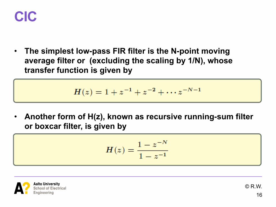
• The simplest low-pass FIR filter is the N-point moving average filter or (excluding the scaling by 1/N), whose transfer function is given by
• Another form of H(z), known as recursive running-sum filter or boxcar filter, is given by
© R.W. 16
CIC decimator
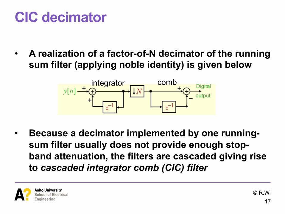
• A realization of a factor-of-N decimator of the running sum filter (applying noble identity) is given below
• Because a decimator implemented by one running-sum filter usually does not provide enough stop-band attenuation, the filters are cascaded giving rise to cascaded integrator comb (CIC) filter
© R.W. 17
integrator comb

CIC Applications
• Down-sampling of the output of sigma-delta analog-to-digital converter
• Typically 16:1 down-sampling CIC filter followed by a 4-path polyphase filter or two half-band filters
© R.W. 18

1-4 stage CIC filters (without decimation)
© R.W.
19

CIC decimator
• Filter length and down-sampling factor needn’t be equal • The structure of a two-stage CIC decimator is shown below
• It can be easily shown that the structure corresponds to a factor-of-R decimator with a length-RN running sum filter
© R.W. 20

CIC decimator
• Further flexibility in the design is obtained by including K feedback paths before and K feedforward paths after the down-sampler
• Typically, the number of sections is 3-5 • Increasing word length is a problem in practice
© R.W. 21
CIC decimator
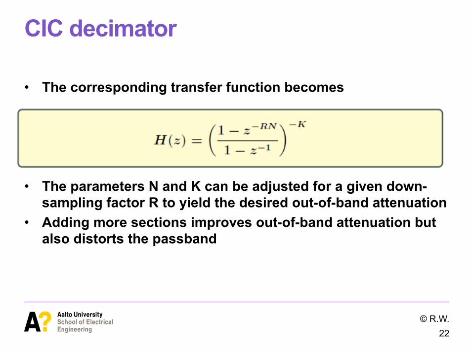
• The corresponding transfer function becomes
• The parameters N and K can be adjusted for a given down-sampling factor R to yield the desired out-of-band attenuation
• Adding more sections improves out-of-band attenuation but also distorts the passband
© R.W. 22

CIC Interpolator
• CIC interpolators are usually used in the last section of the multistage interpolator where the signal is sampled already in a high rate
© R.W. 23
• The structure actually repeats input samples x(k) R times (when starting from zero state)
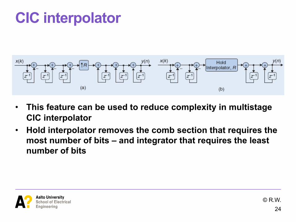
CIC interpolator
• This feature can be used to reduce complexity in multistage CIC interpolator
• Hold interpolator removes the comb section that requires the most number of bits – and integrator that requires the least number of bits
© R.W. 24


![Digital Filter Structures - The Catholic University of Americasip.cua.edu/res/docs/courses/ee515/chapter06/ch6-1.pdf · k k N y[n] k 1dk y[n k] 0 p x[n k] = ... Digital Filter Structures](https://static.fdocuments.net/doc/165x107/5aee5c927f8b9ae53191a7cb/digital-filter-structures-the-catholic-university-of-k-n-yn-k-1dk-yn-k-0-p.jpg)


