File Geodatabase standards - British Columbia · File Geodatabase Standards . for Data Creation,...
57
GeoBC File Geodatabase Standards for Data Creation, Publication, and Distribution Last Updated 22.03.2013
Transcript of File Geodatabase standards - British Columbia · File Geodatabase Standards . for Data Creation,...

GeoBC File Geodatabase Standards
for Data Creation, Publication, and Distribution
Last Updated 22.03.2013

File_Geodatabase_Standards.docx Page 2 of 57
Created by the Geospatial Services, BC Ministry of Forests, Lands and Natural Resource Operations
Comments and Questions: [email protected] Last Updated 22.03.2013

File_Geodatabase_Standards.docx Page 3 of 57
1. Introduction ............................................................................................................. 5 1.1. Document History ............................................................................................... 5 2. File Geodatabase Standards in Brief ....................................................................... 6 3. Detailed File Geodatabase Standards...................................................................... 8 3.1. File Geodatabase Structure/When to use Feature Datasets ................................. 8
3.1.1. Project Level Work ..................................................................................... 8 3.1.2. Data Publication (Data warehouses, BCGW staging area, etc.) ................. 9 3.1.3. Data Distribution (FTP, Folder publication) ............................................. 10 3.1.4. Receiving Data from Contractors ............................................................. 10
3.2. Format for Distribution/Receiving FGDB data ................................................ 11 3.3. Naming Conventions ........................................................................................ 11
3.3.1. Generic Naming Standards ....................................................................... 11 3.3.2. GDB Naming Standards ........................................................................... 12 3.3.3. Feature Dataset Naming Standards ........................................................... 12 3.3.4. Feature Class Naming Standards .............................................................. 12 3.3.5. Field Naming Standard ............................................................................. 13
3.4. Storage Projection and Datum .......................................................................... 14 3.5. XY(and Z) Tolerance ........................................................................................ 14 3.6. XY (and Z) Resolution...................................................................................... 15 3.7. Configuration Keyword .................................................................................... 15 3.8. File Geodatabase Fields .................................................................................... 16
3.8.1. Feature Codes............................................................................................ 16 3.8.2. _Tag Field ................................................................................................. 16 3.8.3. ORCS and ARCS ...................................................................................... 16
3.9. Field Indexing ................................................................................................... 16 3.10. Spatial Indexing ................................................................................................ 17 3.11. Data Integrity .................................................................................................... 17
3.11.1. Repairing Geometry .................................................................................. 17 3.11.2. Topology (Spatial Data Integrity) ............................................................. 17
3.11.2.1. Topology Validation ......................................................................... 19 3.11.2.2. Error Reporting ................................................................................. 19 3.11.2.3. Topology Standards: ......................................................................... 19
3.11.3. Attribute Domains (Attribute Data Integrity) ........................................... 20 3.12. Metadata ............................................................................................................ 21 3.13. Compacting File Geodatabases ......................................................................... 22 3.14. Compressing Data ............................................................................................. 23 4. Tools for Implementing the File Geodatabase Standards ..................................... 24
4.1. Tools Overview ............................................................................................. 24 4.1.1. Checking/Reporting Tool.......................................................................... 24 4.1.2. Create New File Geodatabase with Feature Dataset Tool ........................ 24 4.1.3. Apply Default Topology Tool .................................................................. 24 4.1.4. FGDB Project Close-out Tool .................................................................. 24 4.1.5. FGDB Publication/Distribution Tool ........................................................ 24 4.2. Accessing and Using FGDB Standards Tools .............................................. 24 4.2.1. Internal government employees working on the GIS Terminal Server (GTS) 25

File_Geodatabase_Standards.docx Page 4 of 57
4.2.2. Outside of Government ............................................................................. 25 4.2.3. Adding the FGDB Standards Toolbox to ArcToolbox ............................. 26 4.2.4. Executing FGDB Standards Tools ............................................................ 27 4.2.5. Accessing Help Documentation ................................................................ 27
5. Applying File Geodatabase Standards – Step by Step Directions ........................ 30 5.1. Creating a New Feature Class or Feature Dataset ............................................ 30
5.1.1. Defining Projection to the PCS_Albers Projection ................................... 32 5.1.2. XY Tolerance and Resolution ................................................................... 32 5.1.3. Configuration Keyword ............................................................................ 33
5.2. Indexing Fields.................................................................................................. 33 5.3. Optimizing the Spatial Index ............................................................................ 36 5.4. Repairing Geometry .......................................................................................... 37 5.5. Creating and Applying Topology ..................................................................... 37
5.5.1. Creating a Topology Element ................................................................... 37 5.5.2. Validating Topology ................................................................................. 42 5.5.3. Finding and Fixing Topology Errors ........................................................ 44 5.5.4. Reporting out from Topology ................................................................... 47
5.6. Creating and Applying Attribute Domains ....................................................... 48 5.6.1. Creating a Domain .................................................................................... 48 5.6.2. Applying a Domain ................................................................................... 51 5.6.3. Editing with a Domain .............................................................................. 52 5.6.4. Checking for Attribute Errors ................................................................... 52
5.7. Creating Metadata ............................................................................................. 54 5.8. Compacting a Geodatabase ............................................................................... 56 5.9. Compressing a Geodatabase ............................................................................. 56

File_Geodatabase_Standards.docx Page 5 of 57
1. Introduction The GeoBC File Geodatabase Standards detail the BC Government standards for storing, publishing, and distributing corporate GIS data using ESRI’s file geodatabase (FGDB) data format. File geodatabases, first introduced with ArcGIS 9.2, are ideal for working with GIS data at a project level and for data storage and sharing. They are the natural data format to use with BC government’s ArcGIS software packages from ESRI and offer critical benefits over shapefiles such as:
• The ability to apply data integrity checks for both spatial and attribute data, • Storage in a single file/folder (folder with .gdb extension), • More efficient storage for larger datasets.
Due to the broad range of FGDB capabilities and use scenarios, these standards should be used as guidelines and not as absolute prescriptive law. These standards are endorsed by the BC Ministry of Forest, Lands and Natural Resource Operation’s Geospatial Services Data Management Working Group. They will be updated as software and data use changes necessitate. Please send questions and comments to Chris Ens ([email protected]).
1.1. Document History Publication
Date (DD.MM.YYYY)
Summary of Changes
22.09.2008 Document first published. 26.03.2009 Various spelling corrections.
Added note on Datum transformations in section 3.4. Updated section 4 with new tools for FGDB standards implementation.
02.04.2009 Corrected error with point and line topology rules.
12.04.2010 4.2.1 Updated path to FGDB standards tool in the script warehouse.
23.04.2010 3.3.2; 3.3.4 Updated GDB and feature class naming standards to include examples consistent with standards.
22.03.2013 Full document refresh to reflect changes to software (ArcGIS 10) and government organizational changes since original document created.

File_Geodatabase_Standards.docx Page 6 of 57
2. File Geodatabase Standards in Brief File Geodatabase Structure / Use of Feature Datasets
Full details
Project Level Work
• Use Feature Datasets • Many Feature Classes per Geodatabase more information
Data Publication • Single Feature Class per Geodatabase • No Feature Datasets more information
Data Distribution
• Single Feature Class per Geodatabase except when distributing sets of data
• Use Feature Dataset only when distributing sets of data more information
Receiving Data (from Contractors, etc.)
• Use Feature Datasets • Many Feature Classes per Geodatabase more information
Format for Distribution/Receiving
• Zipped compressed geodatabase (<FGDB name>.gdb.zip)
more information Naming Standards
• Names should strive to be descriptive and concise. See
the Naming Conventions section for full details. Projection and Datum • PCS Albers, NAD 83
more information XY Tolerance • 1/10th positional accuracy (0.1 m for 1:20k data)
more information XY Resolution • Default (0.0001 meters)
more information Configuration Keyword • Default
more information Standard Fields • FEATURE_CODE
more information • _TAG (for linking to other databases/tables) more information • ORCS_ or ARCS_ (for fields with associated managed
government records with ORCS or ARCS numbers) more information
Field Indexing
• Apply to fields that are queried often when there are many records in the table and after editing is complete
more information Spatial Indexing
• Re-calculate spatial indexes when feature classes are complete
more information

File_Geodatabase_Standards.docx Page 7 of 57
Data Integrity
Repair Geometry • Apply the ‘Repair Geometry’ tool to each feature class more information
Topology (Spatial Data Integrity)
Full details • Cluster Tolerance = XY Tolerance • Only feature classes with rules applied to them should
participate in a topology element • More trusted feature classes should be higher ranks
(lower number) • Rules will depend on what spatial relationships require
enforcing. See common rules section for more details. Attribute Domains
(Attribute Data Integrity)
• Apply domains to fields that have specified values or value ranges
more information Metadata
• ArcCatalog’s metadata should be filled in with the key fields required for the Geographic Data Discovery Service. See Metadata section for more details.
Compacting File Geodatabases
• File geodatabases should be compacted once they are ready for distribution or publication.
more information Compressing File Geodatabases
• File geodatabases should be compressed for distribution and publication.
more information

File_Geodatabase_Standards.docx Page 8 of 57
3. Detailed File Geodatabase Standards 3.1. File Geodatabase Structure/When to use Feature Datasets Geodatabases are databases for storing feature classes, raster data, tabular data, tools for processing data, and other related elements for defining data’s behaviour. A feature dataset can be seen as a sub-directory within a geodatabase to store feature classes and elements governing spatial behaviour. Feature datasets can be used to organise data, however, they also apply their spatial properties to their contents. All feature classes in a feature dataset will have the same projection, XY tolerance, and XY resolution. It is a good idea to store feature classes within a feature dataset to ensure that all feature classes share the same projection. It is required to store feature classes inside a feature dataset for applying topology rules to feature classes. All participating feature classes in a topology element must be stored in the same feature dataset. Tabular data, raster data, and toolboxes are stored at the base geodatabase level and cannot be stored inside a feature dataset. Toolboxes are storage bins for storing geoprocessing tools. They can be stored directly within a geodatabase or as a .TBX file. Within a toolbox, toolsets can be used to organise tools into groupings. Tools inside a toolbox can be the ArcGIS system tools from ArcToolbox, ModelBuilder models, or script tools (tools that reference and run scripts). 3.1.1. Project Level Work The following standards apply to using FGDBs for project level data creation, storage, and analysis:
• All feature classes must be within feature datasets. • Feature datasets must conform to the projection, XY tolerance, XY resolution,
and naming conventions defined in the following sections of this document. • All feature classes must conform to configuration, naming conventions, and
metadata standards defined in the following sections of this document. • Where appropriate, feature classes should have attribute domains and topology
elements applied to them. • FGDBs must be compacted and compressed when work is completed. • Multiple feature classes can be within a single feature dataset. • Any ModelBuilder models used in the creation of data should be stored in
toolboxes within the FGDB. Scripts should be stored in an accompanying folder to the FGDB.

File_Geodatabase_Standards.docx Page 9 of 57
Rational for the above standards: • Having each feature class inside a feature dataset ensures that all data has the
same projection, XY tolerance and XY resolution, and allows topology rules to be applied.
• When processing is complete compacting and compressing geodatabases makes them take up less storage space.
• Storing toolboxes within the geodatabase makes them portable with the rest of the project data.
3.1.2. Data Publication (Data warehouses, BC Geographic Warehouse staging
area, etc.) The following standards apply to publishing data to publication directories such as the BC Geographic Warehouse (BCGW) staging area:
• Each geodatabase must have a single feature class that conforms to the projection, XY tolerance, XY resolution, configuration keyword, naming conventions, and metadata standards defined in the following sections of this document.
• FGDBs must be compacted and compressed. • Feature classes must be stored at the base geodatabase level (not in feature
datasets). • Each feature class must be topologically correct.
Rational for the above standards:
• Compacting and compressing geodatabases makes them take up less storage space and makes the data read-only.
• Single feature class per geodatabase limits chances of schema locking. • Single feature class per geodatabase limits the risk of data loss due to file
corruption or loss of files. • Not using feature datasets simplifies the data model since only single feature
classes are stored within each FGDB. • Feature Datasets (and Topology elements) are not required as data should already
be topologically correct before publishing. The project dataset will include topology, not the publication version.

File_Geodatabase_Standards.docx Page 10 of 57
3.1.3. Data Distribution (FTP, Folder publication) The following standards apply to publishing data for distribution on an FTP site or other distribution service:
• When geodatabases are storing single feature classes, feature datasets must not be used.
• Feature datasets may be used to separate data into logical groupings when many feature classes are being distributed as a package inside a single FGDB.
• Feature classes and feature datasets must conform to the standards around projection, XY tolerance, XY resolution, configuration keyword, naming conventions, and metadata defined in the following sections of this document.
• All feature classes must be topologically correct. • FGDBs must be compacted and compressed.
Rational for the above standards:
• Do not use feature datasets (when distributing single feature classes) to simplify the data model.
3.1.4. Receiving Data from Contractors The following standards apply to the geodatabase structure for receiving data from contractors:
• All feature classes should be within feature datasets. • Feature datasets must conform to the projection, XY tolerance, XY resolution,
and naming conventions defined in the following sections. • All feature classes must conform to configuration, naming conventions, and
metadata standards defined in the following sections of this document. • Data integrity must be ensured and checkable:
o Each feature class must have a topology element applied. o Where appropriate, attribute domains must be applied to attribute fields.
• FGDBs must be compacted and compressed.

File_Geodatabase_Standards.docx Page 11 of 57
• Multiple feature classes can be within a single feature dataset. • Any ModelBuilder models or scripts used in the creation of a dataset should be
included as contract deliverables preferably in toolboxes stored within the geodatabase. Scripts should be delivered as separate files along with FGDBs. Script tools should have their scripts imported to reside within the toolbox.
3.2. Format for Distribution/Receiving FGDB data For distribution, file geodatabases must be compressed and then zipped. The zip file should consist of the name of the FGDB followed by ‘.gdb’, to indicate that it is a file geodatabase, followed by the ‘.zip’ extension.
Example: <FGDB name>.gdb.zip
3.3. Naming Conventions Geodatabases use name strings at a variety of levels. Examples include the geodatabase itself, feature datasets, feature classes, tables, domains, and relationship classes. A generic standard that is applicable for all entities will be first described, followed by additional standards applicable to specific entity types. These standards should be applied for data publication and distribution. 3.3.1. Generic Naming Standards
• Name strings should include only: o Alphanumeric characters (letters and numbers) o An underscore character to separate words
• Name strings must not include: o Spaces, periods, dashes, or any other special characters.
• Name strings should be lower case to ensure compatibility on UNIX storage devices.
• If abbreviations must be used, use standard abbreviations to indicate extent, such as forest district codes for example. If letters are to be removed to form an ad-hoc abbreviation, removal of vowels first, is the preferred method.

File_Geodatabase_Standards.docx Page 12 of 57
3.3.2. GDB Naming Standards
• Generic standards apply • The name should be formed using a concatenation of:
o General Descriptor (mandatory) o Spatial extent (optional) Eg. sir, dpc, 082g, bc
Examples: watershed_bc.gdb silviculture_dpg.gdb wildlife_sir.gdb trim_082g.gdb
• When publishing data the geodatabase name should be the same as the name of
the feature class stored within it. (refer to the Data Publication and Feature Class Naming Standards sections).
Examples:
3.3.3. Feature Dataset Naming Standards • Using feature datasets is optional depending on the purpose of the geodatabase
(refer to Geodatabase Structure section). • Generic standards apply. • The name should be formed using a concatenation of:
o General Descriptor (mandatory) o Projection (mandatory for non Albers) Eg. utm12, geo, alb
Examples: water_geo (geographic, which is unprojected) fdp_utm11 (UTM zone 11)
3.3.4. Feature Class Naming Standards
• Generic standards apply. • No limit on length, however, keep in mind that for data that will eventually be
published to SDE, a 32 character limit exists in that storage environment, and shorter names are generally easier to work with.
• Also, for data that will act as a staging area source for the BC Geographic Warehouse (BCGW), the feature class should be named in a consistent manner with the BCGW layer.
• The name should be formed using a concatenation of:

File_Geodatabase_Standards.docx Page 13 of 57
Component Description Applicability Domain Type Examples Subject Descriptor
The principle theme of the dataset
Mandatory User specified ungulate
Type Descriptor
A more specific type description.
Mandatory User specified winter_range
Status Descriptor
Dataset status. Optional Coded value Proposed, draft, legal
Year Year, or year range of data capture
Optional Coded value or range
2003 2001_2007
Spatial Extent Spatial extent code. Optional Coded value or user specified
sir, dmh, 082g
Feature Type Feature geometry type.
Optional Coded Value Poly, line, point, anno, ras
Scale Descriptor
Data capture scale, divided by 1000 (=k), or 1,000,000 (=m).
Optional Coded Value 20k, 50k, 250k, 2m,
Version Dataset version, if multiple versions are present
Optional Coded Value V1, V2, V3, etc
Examples:
Subject Type Status Year Extent Feature Type
Scale Version
ungulate winter_range draft 2006 kor 20k cadastre ici 2007 dco watershed boundary nir 50k ungulate_winter_range_draft_2006_kor_20k cadastre_ici_2007_dco watershed_boundaries_nir_50k Related Links:
Layer File Naming Standards: http://www.data.gov.bc.ca/local/dbc/docs/geo/services/standards-procedures/presentation_view_standards.pdf
3.3.5. Field Naming Standard • Field Names should be descriptive of the field content. • Because Field Names are case sensitive they must be in UPPER CASE for
consistency and for compatibility with Oracle Databases.

File_Geodatabase_Standards.docx Page 14 of 57
3.4. Storage Projection and Datum File geodatabase content will be created in BC’s Standard Albers projection, NAD83 datum. The coordinate units should be meters and stored without offsets (i.e., in direct Albers projection coordinates). Because this projection goes by different names, for consistency with the BC Geographic Warehouse (BCGW) internal government data warehouse, whenever possible, the projection file used should be named “PCS_Albers”. If the “PCS_Albers” projection file is unavailable, ESRIs “NAD 1983 BC Environment Albers” project file is the exact same except for name and can be used instead. For further information see:
• http://www.ilmb.gov.bc.ca/risc/pubs/other/mappro/map.htm • http://spatialreference.org/ref/epsg/3005/
Datum transformation between NAD 27 and NAD 83 must use the Canadian National Transformation version 2 (NTv2). To use the NTv2 grid shift matrix with ArcGIS the files need to be downloaded and installed (already done for BC Government terminal servers). These files can be downloaded from ESRI Canada. For more information on the NTv2 refer this webpage: http://www.geod.nrcan.gc.ca/tools-outils/ntv2_e.php Step by Step Directions
3.5. XY(and Z) Tolerance XY Tolerance (and Z Tolerance), also referred to as Cluster Tolerance in some contexts, is the distance within which two vertexes are considered to be coincident. XY tolerance is a property of feature classes and feature datasets. The XY tolerance of a feature dataset will be applied to all the feature classes stored within it. XY tolerance is applied during topology validation, buffering, overlay operations, and some editing operations to eliminate small errors in feature classes that could otherwise cause undershoots, overshoots, gaps and sliver polygons. When XY tolerance is applied, vertexes within the XY tolerance of each other will be moved to the same location. XY tolerance is not meant to generalize data but to eliminate errors. Too large an XY tolerance will generalize data, compromising its accuracy; while too small an XY tolerance can leave small undershoot and overshoot errors untouched and mean topological operations on coincident geometry will not work as planned. It is recommended to use an XY tolerance an order of magnitude smaller than the data’s accuracy. If the data’s collection accuracy is not known the standard of 1/10th positional accuracy should be used. Positional accuracy is defined as the width of the smallest line visible on a map translated into map units. The smallest line visible on a map is about 0.05 mm. At a scale of 1:20,000 this translates to 1 meter (0.05 mm = 0.00005m; 0.00005m * 20,000 = 1m). So, an acceptable XY tolerance for 1:20,000 scale data is 0.1 meters or 1/10th positional accuracy (1m / 10 = 0.1 m). When setting XY Tolerance for a

File_Geodatabase_Standards.docx Page 15 of 57
feature dataset, use an appropriate tolerance for the most accurate data to be stored within it. The one exception to the rule of 1/10th positional accuracy is large scale data (Cadastre data). Because the BC Geographic Warehouse (BCGW) SDE database has a tolerance of 0.002 meters, to minimize errors if data is migrated to the BCGW we should use 0.002 meters as the smallest XY tolerance for our most precise datasets. Table of appropriate XY Tolerance values by scale of data to be used as a guideline:
Map Scale XY Tolerance Large Scale
(cadastre, etc.) 0.002 meters
1:10,000 0.05 meters 1:20,000 0.1 meters 1:50,000 0.25 meters 1:100,000 0.5 meters 1:250,000 1.25 meters 1:500,000 2.5 meters
1:1,000,000 5 meters 1:2,000,000 10 meters 1:5,000,000 25 meters 1:10,000,000 50 meters
Step by Step Directions
3.6. XY (and Z) Resolution XY resolution (and Z resolution where there are Z coordinates) defines the numeric precision that coordinates are stored with (or the number of decimal places used to store coordinates). XY resolution is defined for feature classes and for feature datasets; however, a feature dataset will enforce its XY resolution on the feature classes stored within it. The default XY resolution is 0.0001 meters translated into the units of the dataset. Increases in storage efficiency and processing performance resulting from using a larger XY resolution are negligible and so the default XY resolution should be used. Step by Step Directions
3.7. Configuration Keyword The configuration keyword defines how data is stored in a geodatabase and can slightly improve performance for specific types of data. The default configuration keyword uses the UTF8 format for data storage which is also the standard for the BC Geographic Warehouse (BCGW) and most operational government oracle databases. So that data storage is compatible with the BCGW and other Oracle databases, the default configuration keyword, ‘DEFAULTS’, should be used. Other keywords optimize storage for text using non-Latin alphabet (TEXT_UTF16), slightly improves storage for

File_Geodatabase_Standards.docx Page 16 of 57
datasets less than 4 GBs (MAX_FILE_SIZE_4GB), or allows for large raster files greater than 1 TB in size (MAX_FILE_SIZE_256TB). Step by Step Directions
3.8. File Geodatabase Fields 3.8.1. Feature Codes Many published datasets have a 10-character feature code. Where this is relevant to a feature class being published, include a character field called ‘FEATURE_CODE’. Values for the codes must be from the list referred to in BC Geographic Feature Catalogue. Where a feature in a FGDB has no classification contact GeoBC Information Services Branch to have one created. When publishing data, every feature class (point, line, polygon) should have a 10-character feature code. This code must be stored in a character field called ‘FEATURE_CODE’. Values for the codes must be from the list referred to in BC Geographic Feature Catalogue. Where a feature in a FGDB has no classification contact GeoBC Information Services Branch to have one created. 3.8.2. _Tag Field When features in an FGDB can be linked to remote data, such as in an Oracle database, give the linking field a ’_TAG’ suffix. The field in the FGDB must be of a correct data type match. If features have no unique identifier the _TAG field is meaningless, and is not required. 3.8.3. ORCS and ARCS For features that have managed government records with ARCS or ORCS numbers associated with them, a field beginning with ‘ARCS_’ or ‘ORCS_’ populated with the ARCS or ORCS record number should be included. ARCS (Administrative Records Classification System) numbers are used for government wide record management. ORCS (Operational Records Classification System) numbers are used for ministry specific record management.
3.9. Field Indexing Field indexes can increase the speed of attribute queries on feature classes and tables in a file geodatabase. Multiple indexes can be applied to different attributes of any table or feature class (unlike with shapefiles), however, at this point multicolumn indexes are not available for the file geodatabase.

File_Geodatabase_Standards.docx Page 17 of 57
Indexes can slightly slow down the speed of editing as for each edit the index is also updated. For this reason, indexes should only be set up once a feature class or table is ready to be used. Each index for a particular feature class or table must have a unique name. Field indexes may be appropriate to implement when the following is true:
• The field is queried often. • There are many records in the table. • Most of the editing is complete.
Step by Step Directions
3.10. Spatial Indexing Spatial indexes should be recalculated when a feature class is complete and ready for publication. Spatial indexes help ArcGIS to locate spatial features quickly when displaying, editing, and querying. ArcGIS spatial indexes for file geodatabases consist of a set of up to three grids that spatial features are indexed to. ArcGIS creates these grids automatically whenever a new feature class is created. Spatial indexes may need to be recalculated for optimization if features are added to a feature class that are different in size from the features already in a feature class. They can be recalculated or set manually through a feature class’s properties or through tools in the geoprocessing framework. Only in rare cases will significant performance enhancements be achieved by manually setting the spatial indexes. Generally, to ensure an optimal spatial index has been created, it is enough to get ArcGIS to recalculate the spatial index for a feature class. Spatial indexes should be recalculated when a feature class is complete and ready for publication. Step by Step Directions
3.11. Data Integrity 3.11.1. Repairing Geometry The ‘Check Geometry’ and ‘Repair Geometry’ tool must be run on all completed feature classes. This Check Geometry tool checks for geometric errors and reports them in a table stored in the geodatabase; and the Repair Geometry tool fixes geometric errors. Errors fixed by this tool include deleting null geometry, deleting short segments (too short for the spatial reference’s units), reorienting incorrectly oriented internal and external rings of polygons, and intersecting where lines self-intersect. Step by Step Directions
3.11.2. Topology (Spatial Data Integrity)

File_Geodatabase_Standards.docx Page 18 of 57
Topology is one tool to help maintain spatial data integrity. In a file geodatabase it is a collection of rules and relationships that, coupled with a set of editing tools and techniques, enables the geodatabase data to more accurately model geometric relationships found in the world. Topology in the file geodatabase is a separate element that resides inside a feature dataset and sets up rules to govern behaviour between features within feature classes and between different feature classes that participate in the topology. A cluster tolerance is employed to shift geometry small distances to ensure that coincident geometry is indeed coincident so that spatial relationships between points, lines, and polygons can be tested and any errors found. A topology element has the following properties:
• A name: Because a topology is its own element within a geodatabase it needs to have a unique name.
• Cluster Tolerance: Similar to the XY tolerance, the cluster tolerance is applied when topology is validated. Feature parts within the cluster tolerance distance of each other will be assumed to be coincident and will be clustered together to reflect this.
• Participating Feature Classes: A list of feature classes participating in the topology element.
• Ranks of Feature Classes: Each participating feature class has a rank referring to how trusted or accurate the data is. Lower ranked features will be snapped to higher ranked features and equally ranked features will be clustered together during the validation process.
• Topology Rules: Topology Rules define geometric relationships between features of a single feature class or between features of different feature classes. Rules can be exported to a .RUL file and imported to a new topology element. To simplify workflow, a standard set of rules can be saved to a .RUL file and imported into new topology elements.
Some general rules governing how topology elements are set up: • Topology elements must reside within a feature dataset. • All participating feature classes must reside within the same feature dataset as the
topology element. • A feature dataset may have many topology elements. • Each topology element may have many participating feature classes with many
rules applied to each feature class. • Each feature class may participate in only one topology element. • Subtypes of feature classes behave as feature classes within a topology element
meaning each subtype may have different rules applied to it.
File_Geodatabase_Standards.docx Page 19 of 57
3.11.2.1. Topology Validation Topology validation first applies the cluster tolerance to the participating feature classes, shifting the geometry so that features are coincident, and then applies the topology rules to find errors. When the cluster tolerance is applied equally ranked feature parts will be clustered together and lower ranked feature parts will be snapped to higher ranked feature parts. Topology should only be validated in an ArcMap edit session so that it can be undone if it is discovered that the geometry shifts too much due to too large a cluster tolerance being employed. Topology validated in ArcCatalog can not be undone. Once topology has been validated errors can be viewed and fixed or marked as exceptions within an ArcMap edit session using tools on the Topology toolbar. 3.11.2.2. Error Reporting Once a topology element has been validated a report of the errors and exceptions can be viewed through the topology element’s properties on the ‘Errors’ tab by pressing the ‘Generate Summary’ button. This summary can be exported to a .txt file using the ‘Export to File…’ button. 3.11.2.3. Topology Standards: The following standards for topology should be followed for all feature classes being published, shared, or received from contractors. In addition, when receiving data from contractors a topology report CSV file should accompany the geodatabase named with the same name as the topology element. This report will allow quick review of what rules have been applied to what feature classes and where there are any exceptions to these rules (There should not be any errors in a completed dataset.).
Cluster Tolerance: • Should be set to an appropriate scale for the data so that data is not shifted too
much. The smallest cluster tolerance allowed is the XY tolerance of the feature dataset. In most cases this will be the appropriate cluster tolerance to use.
Participating Feature Classes:
• Only feature classes that have rules related to them should participate in the topology so that cluster tolerance is not applied and geometry shifted needlessly.
Ranks:
• When more than one feature class is participating in the topology element more accurate or trusted datasets should be higher ranks (lower numbers) than less accurate and less trusted data.

File_Geodatabase_Standards.docx Page 20 of 57
Rules: What rules to apply will depend on what the data is modelling and how its features spatially relate to each other and relate to features in other feature classes. Listed below are common rules that will apply to most datasets. There will be times when additional rules will need to be applied when these rules are not appropriate. Polygons: • Must not overlap • Must not have gaps (The exterior boundary line work will always be an
exception when this rule is applied. The idea is to not have ‘holes’ in the data but the rule will flag as errors wherever features are not coincident with other features.)
• Must be covered by feature class of – to be applied with a project boundary feature class to make sure features fall within the project area.
Lines: • Must not have pseudonodes – to remove needless nodes and merge
together lines • Must not self intersect – to guard against small digitizing errors • Must not self overlap – to guard against small digitizing errors • Must be inside – to be applied with a project boundary feature class to
make sure features fall within the project area. Points:
• Must be properly inside polygons - to be applied with a project boundary feature class to make sure features fall within the project area
Step by Step Directions 3.11.3. Attribute Domains (Attribute Data Integrity)
Attribute domains define rules for attribute value behaviour and are used to enforce attribute data integrity. They help to ensure data is entered correctly the first time and enable attribute value validation. There are two types of domains: Coded and Range. Coded value domains define a list of valid values (along with descriptions of these values). During editing, fields with coded value domains applied to them will have a drop-down list of values to pick from preventing the user from miss-typing entries. Range domains define valid ranges for numeric and date fields. Both range and coded value domains can be validated (checked for errors) in ArcMap using either the ‘Data Reviewer’ extension or in an edit session using the ‘Validate Features’ command found on the ‘Editor’ pull-down menu on the ‘Editor’ toolbar. Even with domains applied to fields it is possible to enter incorrect values when using the ‘Calculate Field’ tool, and so all fields with domains should be validated using the ‘Validate Features’ command.

File_Geodatabase_Standards.docx Page 21 of 57
Attribute Domain Standards
• Whenever fields have specific values or should be confined to a range of values, domains must be implemented to improve consistency of data entry and to enable the values to be validated.
• When data is being edited by a third party, domains must to be applied to specified fields to ensure data is consistently entered and can be checked. Tables of defined domain values can be provided so they can be imported to domains using the ‘Table to Domain’ geoprocessing tool.
Step by Step Directions
3.12. Metadata Every FGDB created in ArcCatalog will contain basic information on the ‘Description’ viewing tab. It is important to add pertinent information about your data using the editor provided and should contain the mandatory fields in the Geographic Data Discovery Service (http://apps.gov.bc.ca/pub/geometadata/home.do) as well as other recommended standard fields. See table below for mandatory and recommended fields. To be consistent with national standards, metadata should be entered using the “North American Profile of ISO19115 2003” metadata style. The Geographic Data Discovery Services metadata is also based on an ISO 19115 style. The default metadata style for ArcGIS (“Item Description”) does not have the required fields to capture key information. Mandatory Criteria
(for Corporate Metadata)
Description ArcCatalog Metadata XML Editor Location
Title Title of Dataset Overview section -> Item Description page -> Title text box
Description One or two sentences describing the dataset.
Overview section -> Item Description page -> Description box
Data Custodian Organisation
The data owner organization. Overview section -> Citation Contacts page -> New Contact / Contact; Complete the Organization text box and mark Role as ‘Custodian’
Dates (Creation, Publication, Revision)
Dates data created, published, revised.
Overview section -> Citation page -> Dates
Resource Status Complete, In Progress, etc. Resource section -> Details page -> New Status / Status
Update Cycle How often is this dataset updated? Or when will it be updated next?
Resource section -> Maintenance page -> Update Frequency; Next Update
Purpose Intended Use of the Data. Overview section -> Item Description page -> Summary text box
Contact Information / Role
Point of contact. Custodians delegates with business
Resource section -> Points of Contact page

File_Geodatabase_Standards.docx Page 22 of 57
knowledge. Use Limitations Limitations affecting the
fitness of the use of the data. (ex. “Not for Navigation”)
Overview section -> Item Description page -> New Use Limitations / Use Limitations text box
Security Classification Is this data restricted to certain people?
Resource section -> Constraints page -> New Security Constraints / Security Constraints Classification pull-down menu:
Unclassified = general access Restricted = government only
Use New Use Limitations / Use Limitations text box for additional constraints on access and use.
Recommended Criteria
Data Distribution Instructions
Instructions on how to obtain the data.
Resource section -> Distribution page -> New Distributor / Distributor -> New Ordering Process / Ordering Process
Data’s Scale The scale the data is meant to be viewed at.
Resource section -> Details page -> Scale Resolution
Data Completeness How complete is the data Overview section -> Item Description page -> New Use Limitation / Use Limitation
Data Accuracy Spatial accuracy of the dataset including Scale.
Overview section -> Item Description page -> New Use Limitation / Use Limitation
Spatial Reference The Projection and Datum Resource section -> Spatial Reference page (automatically filled in)
Geographic Extent Extent of the dataset. Resource section -> Extent page -> Extent -> Bounding Box (automatically filled in)
History of Data How the data came to be. For each process step to create the data, what was done and who did it.
Resource section -> Lineage page -> New Process Step / Process Step
Attribute Domain Explanations
An explanation of each attribute and its corresponding values.
Resource section -> Fields page -> expand attribute list & attribute properties -> use Enumerated Domain or Range Domain options.
Reference to Data Dictionary
Any reference to data dictionaries for this dataset.
Resource section -> Details page -> Supplemental Information text box
Other Relevant Information
Any other relevant information.
Resource section -> Details page -> Supplemental Information text box
Step by Step Directions
3.13. Compacting File Geodatabases Geodatabases should be compacted once editing operations are complete. As features are added and deleted from feature classes, geodatabases become fragmented on the disk causing a decrease in performance due to the larger file size and the increase

File_Geodatabase_Standards.docx Page 23 of 57
in record-seeking operations when using the data. Compacting a geodatabase re-orders records and eliminates free space, reducing the size of the geodatabase and increasing performance of processing. Step by Step Directions
3.14. Compressing Data Feature classes should be compressed once they are in a complete or publishable state. Unlike compacting a geodatabase where data is re-ordered to be more efficiently stored on the server, compressing a geodatabase applies an algorithm to vector and table data to reduce redundancy for more efficient storage. Compression varies from dataset to dataset but on average, a compressed dataset is about ½ its uncompressed size. A compressed geodatabase is in a read-only state. Apart from editing the name, attribute indexes, and metadata, no editing is permitted. Compressed data, however, can continue to be viewed and used. Compression/uncompression can be applied to the contents of an entire FGDB, to the contents of a feature dataset, or to individual feature classes or tables. Feature datasets and their contents are compressed or uncompressed as a single entity - feature classes within a feature dataset cannot be compressed or uncompressed individually. Furthermore, compressed feature classes cannot be added to topology elements. Compressed feature classes and tables dataset will display ‘(compressed)’ in the ‘Type’ field of ArcCatalog when viewing geodatabase contents. The compression state of a feature class or table is also listed on the ‘General’ tab of its properties window in ArcCatalog. Step by Step Directions
File_Geodatabase_Standards.docx Page 24 of 57
4. Tools for Implementing the File Geodatabase Standards
Tools have been developed to automate the application of the file geodatabase standards so that, wherever possible, tasks that can be automated, have been. Section 4.1 gives an overview of the current geodatabase standards. Section 4.2 explains how to access these tools and their help documentation.
4.1. Tools Overview 4.1.1. Checking/Reporting Tool This tool inventories the contents of a file geodatabase and reports out into a text file a summary of the entities and their properties. The output report consists of two sections. The first section contains a consise summary of the entities found within the geodatabase. The second section contains detailed information about each entity. 4.1.2. Create New File Geodatabase with Feature Dataset Tool The Create New File Geodatabase tool is a shortcut to create a new FGDB with a feature dataset in the BC Albers projection and the specified XY tolerance. If the geodatabase already exists, the script will continue and create the new feature dataset within it. 4.1.3. Apply Default Topology Tool The Apply Default Topology tool creates a new topology element in the indicated feature dataset, applies the standard generic topology rules to the selected feature classes, and optionally validates the topology to find errors. Users may wish to edit the topology element afterwards to apply additional more specific topology rules. 4.1.4. FGDB Project Close-out Tool The FGDB Project Close-out tool is used to close-out a FGDB once a project is complete. It compacts the geodatabase, compresses the geodatabase, re-calculates the spatial indexes of feature classes, runs the Check Geometry command, and (optionally) runs the Repair Geometry command. 4.1.5. FGDB Publication/Distribution Tool The Publication and Distribution tool prepares individual feature classes for publication and/or distribution by copying them to their own geodatabases that conform to the publication standards. The tool puts selected feature classes each in their own FGDB named the same as the feature class name, compresses the new FGDB, and (optionally) zips the FGDB giving it a name <FGDB name>.gdb.zip.
4.2. Accessing and Using FGDB Standards Tools Internal government users can access the FGDB Standards tools through the Script Warehouse (See section 4.2.1). Users outside of the BC government can access these tools through the data distribution service (See section 4.2.2).

File_Geodatabase_Standards.docx Page 25 of 57
There are two versions of the tools and toolboxes. One was created for ArcGIS 9.2 and the other updated for ArcGIS 10.0. The 10.0 updated tools were re-written to use the arcpy site package and includes an additional default topology rule in the Apply Default Topology tool that was new in ArcGIS 10.0. The 9.2 tools will work in ArcGIS 9.2 and newer releases. The ArcGIS 10.0 tools will work in ArcGIS 10.0 and newer releases. 4.2.1. Internal government employees working on the GIS Terminal Server (GTS) The File Geodatabase Standards Tools are located in the Script Warehouse:
P:\corp\script_whse\python\Utility_Misc\Published\FGDBStandardsTools If the P: drive is not already mapped it should be mapped as:
\\Giswhse.env.gov.bc.ca\whse_np Each tool and their required scripts are located in individual folders. The master toolbox, FGDBStandarrdsTools.tbx, contains script tools to run all the File Geodatabase Standards Tools. See section 4.2.3 and 4.2.5 below for instructions on how to add these tools to ArcToolbox and how to access their help documentation. 4.2.2. Outside of Government For those outside of the BC government networks, the File Geodatabase Standards Tools can be downloaded through DataBC’s Data Distribution Service (https://apps.gov.bc.ca/pub/dwds/home.so) or follow the directions below for direct access.
1) Click on the ‘Order’ button in the metadata record for the FGDB Standards Tools: https://apps.gov.bc.ca/pub/geometadata/metadataDetail.do?from=search&edit=true&showall=showall&recordSet=ISO19115&recordUID=55759

File_Geodatabase_Standards.docx Page 26 of 57
2) Confirm that your order is correct, enter your email addresss, check the Terms and Conditions box, and click on ‘Submit Order’.
3) You will receive an email confirming your order has been submitted and a second
email once your order is ready to be downloaded.
4) Download and unzip the zip file with the link in the second email.
4.2.3. Adding the FGDB Standards Toolbox to ArcToolbox
1) Open ArcToolbox • In ArcCatalog or ArcMap open ArcToolbox:
o Geoprocessing menu -> ArcToolbox

File_Geodatabase_Standards.docx Page 27 of 57
2) Add the FGDBStandardsTools toolbox into ArcToolbox • Drag and drop the ‘FGDBStandardsTools’ toolbox into ArcToolbox • OR Right-click in ArcToolbox -> Add Toolbox....
3) Save Settings to ‘Default’ So that the new toolbox will be in ArcToolbox in other ArcGIS applications when they are opened we must save our Environment Settings to ‘Default’:
• Righ-click in ArcToolbox -> Save Settings -> To Default
4.2.4. Executing FGDB Standards Tools Execute the FGDB standards tools as you would any other system ArcGIS tool:
• Double-click on the tool in ArcToolbox and complete the dialog box. 4.2.5. Accessing Help Documentation
File_Geodatabase_Standards.docx Page 28 of 57
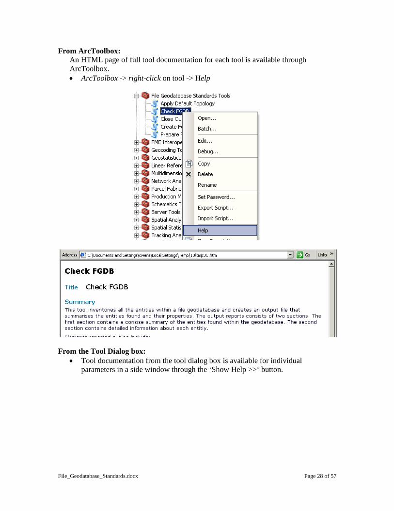
From ArcToolbox: An HTML page of full tool documentation for each tool is available through ArcToolbox. • ArcToolbox -> right-click on tool -> Help
From the Tool Dialog box:
• Tool documentation from the tool dialog box is available for individual parameters in a side window through the ‘Show Help >>‘ button.

File_Geodatabase_Standards.docx Page 29 of 57
• The complete Help documentation HTML page can be brought up through the ‘Tool Help’ button on the help side window.

File_Geodatabase_Standards.docx Page 30 of 57
5. Applying File Geodatabase Standards – Step by Step Directions
5.1. Creating a New Feature Class or Feature Dataset ............................................ 30
5.1.1. Defining Projection to the PCS_Albers Projection ................................... 32 5.1.2. XY Tolerance and Resolution ................................................................... 32 5.1.3. Configuration Keyword ............................................................................ 33
5.2. Indexing Fields.................................................................................................. 33 5.3. Optimizing the Spatial Index ............................................................................ 36 5.4. Repairing Geometry .......................................................................................... 37 5.5. Creating and Applying Topology ..................................................................... 37
5.5.1. Creating a Topology Element ................................................................... 37 5.5.2. Validating Topology ................................................................................. 42 5.5.3. Finding and Fixing Topology Errors ........................................................ 44 5.5.4. Reporting out from Topology ................................................................... 47
5.6. Creating and Applying Attribute Domains ....................................................... 48 5.6.1. Creating a Domain .................................................................................... 48 5.6.2. Applying a Domain ................................................................................... 51 5.6.3. Editing with a Domain .............................................................................. 52 5.6.4. Checking for Attribute Errors ................................................................... 52
5.7. Creating Metadata ............................................................................................. 54 5.8. Compacting a Geodatabase ............................................................................... 56 5.9. Compressing a Geodatabase ............................................................................. 56
5.1. Creating a New Feature Class or Feature Dataset Geodatabases are created either through right-clicking in ArcCatalog or through geoprocessing tools. Before a feature class or feature dataset can be made, there must first be a geodatabase for it to exist in. To create a new FGDB:
• Right-click in ArcCatalog -> New -> File Geodatabase
• Give the new File Geodatabase a name.

File_Geodatabase_Standards.docx Page 31 of 57
A file geodatabase can also be created using the ‘Create File GDB’ geoprocessing tool located in the ‘Data Management Tools’ toolbox and ‘Workspace’ toolset. To create a new feature dataset or feature class:
• Right-click on the new file geodatabase -> New -> Feature Dataset… or Feature Class…
For Feature Datasets the ‘New Feature Dataset’ wizard will appear. This wizard will prompt you for a name for the feature dataset, the coordinate system, and the XY Tolerance. Follow sections 5.1.1 and 5.1.2 below for directions on filling out each of these criteria. For Feature Classes the ‘New Feature Class’ wizard will appear. The first screen of this wizard prompts for a name for the feature class, its geometry type (point, line, polygon, etc.), and whether it has M values and Z values. The next tabs help define the coordinate system, the XY Tolerance and Resolution, and the Configuration Keyword. See sections 5.1.1 to 5.1.3 below for directions through these tabs.
A feature dataset or feature class can also be created using the ‘Create Feature Dataset’ geoprocessing tool located in the ‘Data Management Tools’ toolbox and the ‘Workspace’

File_Geodatabase_Standards.docx Page 32 of 57
toolset and the ‘Create Feature Class’ geoprocessing tool located in the ‘Data Management Tools’ toolbox and the ‘Feature Class’ toolset. 5.1.1. Defining Projection to the PCS_Albers Projection If working on the internal government terminal server in ArcGIS 10, choose the “PCS_Albers” projection file that is available at the base coordinate systems directory.
If the PCS_Albers projection file is not available use ESRIs “NAD 1983 BC Environment Albers” projection file which is the exact same except for name. This project file can also be downloaded form http://spatialreference.org/ref/epsg/3005/. Back to Standards Section
5.1.2. XY Tolerance and Resolution The XY Tolerance and Resolution tab on the ‘New Feature Dataset’ or ‘New Feature Class’ wizard prompts the user to define the XY tolerance and resolution. Both of these settings can only be set when first creating the geodatabase element - they cannot be edited once created. The XY tolerance should be appropriate for the scale of the data. See the standards section for details. The default resolution should be accepted.
Back to Standards Section

File_Geodatabase_Standards.docx Page 33 of 57
5.1.3. Configuration Keyword The Configuration Keyword tab on the ‘New Feature Class’ wizard prompts the user to define the configuration keyword which defines how character data is stored in the database. This setting cannot be changed once it is set. The default configuration keyword is recommended. See the standards section for details.
Back to Standards Section
5.2. Indexing Fields Field indexes are created and deleted through a feature class’s or table’s properties or by using geoprocessing tools. Using ArcCatalog:
1. Go into the properties for a feature class or table to the Indexes tab. • Right-click on the feature class or table -> Properties… -> Indexes tab

File_Geodatabase_Standards.docx Page 34 of 57
Existing indexes are listed in the Attribute Indexes box and their properties below.
2. Press the ‘Add…’ button to add an attribute index. 3. In the ‘Add Attribute Index’ window:
• Give the index a name • Select the field to index and use the arrow to move it to the ‘Fields
Selected’ box.

File_Geodatabase_Standards.docx Page 35 of 57
Note: With file geodatabases there are no unique or ascending indexes or multi-field indexes. Only a single field should be in the ‘Fields Selected’ box.
4. Press the ‘OK’ to accept the index properties. 5. Press ‘OK’ to create the index and close the properties window or ‘Apply’ to
create the index but leave properties open. An index can be deleted from the ‘Indexes’ tab of the properties window by highlighting the index in the ‘Attribute Indexes’ window and pressing the ‘Delete’ button. Using geoprocessing tools:
Use the ‘Add Attribute Index’ and ‘Remove Attribute Index’ geoprocessing tools to manage attribute indexes. These tools are found in the ‘Indexes’ toolset within the ‘Data Management Tools’ toolbox.
Back to Standards Section

File_Geodatabase_Standards.docx Page 36 of 57
5.3. Optimizing the Spatial Index Spatial indexes can be recalculated/optimized either through a feature class’s properties in ArcCatalog or using geoprocessing tools. Through ArcCatalog:
1. Go into the properties for a feature class to the ‘Indexes’ tab. • Right-click on the feature class or table -> Properties… -> Indexes tab
The ‘Spatial Index’ box is at the bottom of the ‘Indexes’ tab.
2. The ‘Spatial Index’ box has three buttons:
• Use the ‘Recalculate’ button to recalculate the spatial index. • Use the ‘Edit…’ button to manually edit the spatial index. • Use the ‘Delete’ button to remove the spatial index.
Recalculating the spatial index is sufficient for optimizing a feature classes spatial reference.
3. Press ‘OK’ to save changes and close the properties window.
To optimize (recalculate) the spatial index through the geoprocessing framework:
• Run the ‘Add Spatial Index’ tool (in the ‘Indexes’ toolset within the ‘Data Management Tools’ toolbox) on the feature class with ‘0’ (Zero) selected for the three ‘Spatial Grid’ parameters.
Back to Standards Section

File_Geodatabase_Standards.docx Page 37 of 57
5.4. Repairing Geometry The two tools available to help identify and repair geometry errors are located in the ‘Features’ toolset within the ‘Data Management Tools’ toolbox. The Check Geometry tool checks the geometry of one or more feature classes and produces an output table summarizing errors found. The Repair Geometry tool finds and repairs geometry of a single feature class. To repair geometry of a feature class:
1. Run the ‘Check Geometry’ tool if you desire to have a record of what errors there are (if any).
2. Run the ‘Repair Geometry’ tool to find and repair geometry errors.
Back to Standards Section
5.5. Creating and Applying Topology Topology elements are used to help model spatial relationships within a feature class or between feature classes. Once a topology element is defined, data can be validated for specific spatial relationships and errors can be found and fixed. Note: Creating and applying topology elements requires “Standard” or “Advanced” licensinsing level of ArcGIS. Topology cannot be created using the “Basic” licensing level of ArcGIS. 5.5.1. Creating a Topology Element Topology elements are created within a feature dataset and used to apply rules to feature classes within the same feature dataset. Topology elements can be created using ArcCatalog or using geoprocessing tools. To create a topology element using ArcCatalog:
1. Open up the ‘New Topology’ Wizard by right-clicking on a feature dataset -> New -> Topology…

File_Geodatabase_Standards.docx Page 38 of 57
2. Give the topology element a name and a cluster tolerance: • Press ‘Next’ to go to the wizard screen for entering the name and cluster
tolerance. • Give the topology element a name that will be unique within the file
geodatabase. • Give the topology element an appropriate cluster tolerance for the feature
classes that rules will be defined for (usually based on the most accurate participating feature class).
Note: The cluster tolerance cannot be smaller than the XY tolerance of the feature dataset it is within. See the XY tolerance standards section for guidelines on defining the cluster tolerance.
• Press ‘Next’ to go on to the next wizard window.
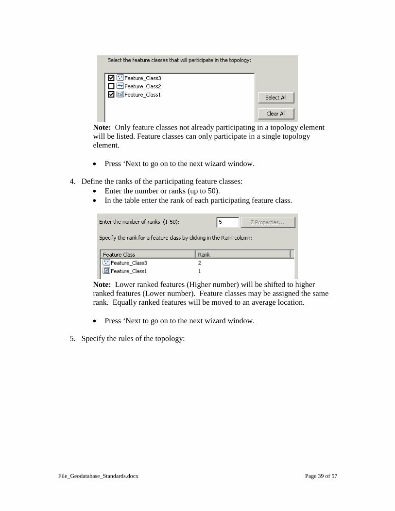
3. Identify participating feature classes: • Choose feature classes to participate in the topology element from the list
of available feature classes in the feature dataset.
File_Geodatabase_Standards.docx Page 39 of 57
Note: Only feature classes not already participating in a topology element will be listed. Feature classes can only participate in a single topology element. • Press ‘Next to go on to the next wizard window.
4. Define the ranks of the participating feature classes:
• Enter the number or ranks (up to 50). • In the table enter the rank of each participating feature class.
Note: Lower ranked features (Higher number) will be shifted to higher ranked features (Lower number). Feature classes may be assigned the same rank. Equally ranked features will be moved to an average location. • Press ‘Next to go on to the next wizard window.
5. Specify the rules of the topology:

File_Geodatabase_Standards.docx Page 40 of 57
• Press the ‘Add Rule…’ button to bring up the ‘Add Rule’ window for adding a new rule.
• In the ‘Add Rule’ window select the rules and feature classes to apply them to. The ‘Rule Description’ box explains the rules both textually and visually.
Note: Refer to the ArcGIS Geodatabase Topology Rules poster for further details on what rules exist and how they are applied: http://resources.arcgis.com/en/help/main/10.1/01mm/pdf/topology_rules_poster.pdf
• Press ‘OK’ to add the rule. • Use the ‘Add Rule…’ button to continue adding more rules or the
‘Remove’ and ‘Remove All’ buttons to remove rules. • The ‘Load Rules…’ and ‘Save Rules…’ buttons are used to export a set of
rules to a .RUL file or to import in rules from a .RUL file.

File_Geodatabase_Standards.docx Page 41 of 57
• Press ‘Next’ to go on to the next ‘Summary’ wizard window.
6. Finish completing the topology element:
The last window of the ‘New Topology’ wizard summarizes the properties defined for the new topology element.
• Press ‘Finish’ to complete the topology element.

File_Geodatabase_Standards.docx Page 42 of 57
• Choose ‘No’ when prompted to validate topology.
Note: Topology validated in ArcCatalog cannot be undone. It is safer to validate topology in an ArcMap edit session where the validation can be undone.
To create a topology model using geoprocessing tools:
The ‘Topology’ toolset within the ‘Data Management Tools’ toolbox contains tools for creating and editing topology elements. Some of these tools are explained below:
• Create Topology – The Create Topology tool creates a new topology element prompting the user for the feature dataset location, the name of the topology element, and the cluster tolerance.
• Add Feature Class to Topology – Add Feature Class to Topology tool adds a feature class to a topology element including the rank of the new feature class.
• Add Rule to Topology – The Add Rule to Topology tool adds a new rule to a topology and applies it to one of the participating feature classes.
Back to Standards Section 5.5.2. Validating Topology When validating topology, the cluster tolerance is applied to participating features, shifting geometry to make features coincident. Lower ranked features are moved to higher ranked features and equally ranked features are clustered to an average location. Next, topology rules are evaluated to identify topology errors. It is safest to validate topology in an ArcMap edit session so that the validation (and any geometry shifts) can be undone if it is found that too large a cluster tolerance was used. To validate topology in an ArcMap:
1. Load the topology element and its participating feature classes into the ArcMap session:

File_Geodatabase_Standards.docx Page 43 of 57
2. Make the ‘Editor’ and ‘Topology’ toolbar visible. 3. Start an Edit session:
• Editor pulldown menu -> Start Editing
4. Use one of the ‘Validate Topology’ buttons to validate the topology:
Validate Selected Areas – only validate area selected by cursor.
Validate Current Extent – only validate the current map view area. Once validation is complete, errors will show up as features in the ArcMap map window:
To validate topology through the geoprocessing framework use the ‘Validate Topology’ tool found in the ‘Topology’ toolset within the ‘Data Management Tools’ toolbox. Validating topology through the geoprocessing framework cannot be undone and will permanently alter participating feature classes. Back to Standards Section
File_Geodatabase_Standards.docx Page 44 of 57
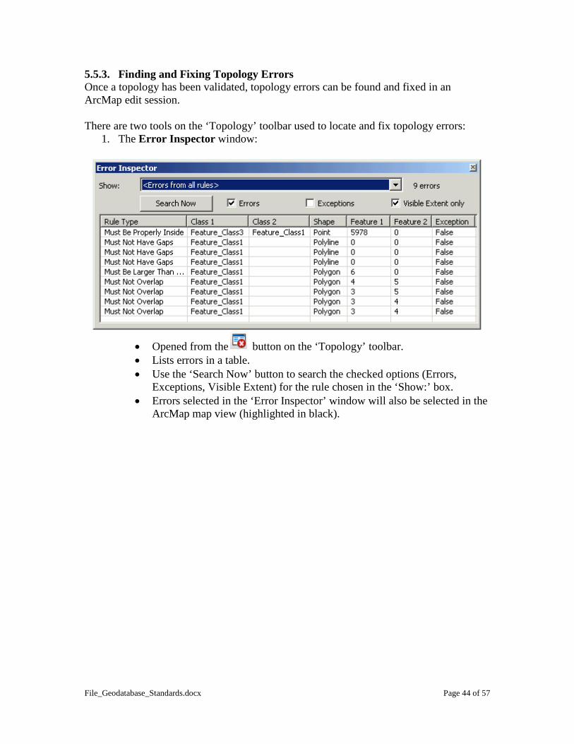
5.5.3. Finding and Fixing Topology Errors Once a topology has been validated, topology errors can be found and fixed in an ArcMap edit session. There are two tools on the ‘Topology’ toolbar used to locate and fix topology errors:
1. The Error Inspector window:
• Opened from the button on the ‘Topology’ toolbar. • Lists errors in a table. • Use the ‘Search Now’ button to search the checked options (Errors,
Exceptions, Visible Extent) for the rule chosen in the ‘Show:’ box. • Errors selected in the ‘Error Inspector’ window will also be selected in the
ArcMap map view (highlighted in black).

File_Geodatabase_Standards.docx Page 45 of 57
• Errors can be sorted alphabetically by clicking on the ‘Error Inspector’ table headers.
• Many errors can be selected at once. • Additional options are available by right-clicking on errors in the ‘Error
Inspector’ window.

File_Geodatabase_Standards.docx Page 46 of 57
• The middle section of this window lists automatic fixes available for
the particular error. • The bottom section gives options for marking an Error as an
Exception or an Exception as an Error. Once an error has been marked as an exception it will no longer be visible – it is as if it has been fixed.
2. The ‘Fix Topology Error’ tool : • Selects errors in the map view. • Errors selected with this tool will also be selected in the ‘Error Inspector’
window. • Selection options can be defined in the properties of the topology element
under the ‘Selection’ tab. The properties window is accessed by right-clicking on the topology element in the ArcMap table of contents.
• Right-clicking with this tool in the ArcMap map window will bring up the
same options as right-clicking in the ‘Error Inspector’ does.

File_Geodatabase_Standards.docx Page 47 of 57
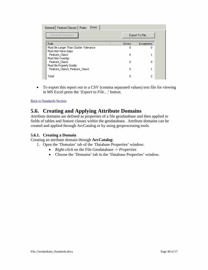
Topology error fixing is an iterative process. Once errors have been fixed the topology should be validated again to see if there are any new errors. When re-validating, only features that have had geometry changes will be validated. Any new errors will need to be either fixed or marked as exceptions and re-validated again. Continue with this process until no errors remain after validating. Back to Standards Section 5.5.4. Reporting out from Topology Once a topology element has been validated a report of the errors and exceptions can be viewed through the topology element’s properties on the ‘Errors’ tab by pressing the ‘Generate Report’ button.
• In ArcCatalog (or ArcMap) right-click on the topology element -> Properties and choose the Errors tab.
• Press the ‘Generate Summary’ button to generate the summary report of all the errors and exceptions by feature class for the topology.
File_Geodatabase_Standards.docx Page 48 of 57
• To export this report out to a CSV (comma separated values) text file for viewing in MS Excel press the ‘Export to File…’ button.
Back to Standards Section 5.6. Creating and Applying Attribute Domains Attribute domains are defined as properties of a file geodatabase and then applied to fields of tables and feature classes within the geodatabase. Attribute domains can be created and applied through ArcCatalog or by using geoprocessing tools. 5.6.1. Creating a Domain Creating an attribute domain through ArcCatalog:
1. Open the ‘Domains’ tab of the ‘Database Properties’ window: • Right-click on the File Geodatabase -> Properties • Choose the ‘Domains’ tab in the ‘Database Properties’ window.

File_Geodatabase_Standards.docx Page 49 of 57
2. Enter the domain name and description: • Enter the domain name and give it a description in the ‘Domain Name’
and ‘Description’ columns of the top part of the ‘Domains’ tab. The domain name will be used to assign the domain to a field and its description is used simply to describe a domains purpose or use.
3. Enter the Domain properties: Field Type:
Domains are assigned to a particular field type. For example, text field domain types can only be assigned to text fields. Field properties must also be able to accommodate the values assigned to the domain (field width, etc.).
Domain Type: Range domains apply to numeric or date fields. When a domain type of ‘Range’ is chosen, ‘Minimum value’ and ‘Maximum value’ properties need to be completed to specify the minimum and maximum values in the permitted range.

File_Geodatabase_Standards.docx Page 50 of 57
Coded Value domains specify discrete values for a particular field. They can be applied to numeric, date, or text fields. When the coded values ‘Domain Type’ is selected codes and their descriptions are entered in the ‘Coded Values’ table at the bottom of the ‘Domains’ tab. Codes are the actual code to be populated as the field value, however, users will see the codes descriptions when viewing or populating the data.
Split Policy: The split policy defines how feature attributes will be populated if a feature is split into multiple new features. For coded value domains there are the options to duplicate the current value or to assign the default value to new features. Range domains offer an additional option to calculate a value based on a geometric ratio.
Merge Policy: The merge policy defines how feature attributes will be populated if multiple features are merged into a single new one. For coded value domains the only option is to assign the new attribute the default value. Range domains add options to sum the values or do a weighted average.
Creating an attribute domain using geoprocessing tools:
Geoprocessing commands used to create and update domains are located in the ‘Domains’ toolset within the ‘Data Management Tools’ toolbox.
• Create Domain tool – The Create Domain tool is used to create a new domain for a geodatabase and complete its properties (except for the range or coded values).
• Add Coded Value to Domain tool – The Add Coded Value to Domain tool adds a coded value and description to a coded value domain.

File_Geodatabase_Standards.docx Page 51 of 57
• Set Value For Range Domain tool – The Set Value For Range Domain tool sets the minimum and maximum values in a range domain.
• Table To Domain tool – The Table to Domain tool creates a new coded value domain from a table of codes and descriptions.
• Domain To Table tool – The Domain to Table tool exports a coded value domain to a table so that the ‘Table To Domain’ tool can be used to create the same domain in a different geodatabase.
Back to Standards Section 5.6.2. Applying a Domain Once a domain has been created as a geodatabase property it can then applied to fields of tables or feature classes within the geodatabase. Applying an attribute domain through ArcCatalog:
1. Open up the properties of a feature class or table to the ‘Fields’ tab: • Right-click on the feature class or table -> Properties • Choose the ‘Fields’ tab in the properties window.
2. Select the field to add a domain to:
• In the upper table of the ‘Fields’ tab select the field to add a domain to.
3. Apply the domain to the selected field: • In the ‘Field Properties’ box select the domain to apply from the ‘Domain’
drop box.
Note: Only domains from the current geodatabase that match the field type will be listed in the ‘Domains’ drop box.
4. Press ‘OK’ to apply the settings.
Applying an attribute domain using geoprocessing tools:
Use the ‘Assign Domain To Field’ tool (located in the ‘Domains’ toolset within the ‘Data Management Tools’ toolbox) to assign a domain to a field.
Back to Standards Section

File_Geodatabase_Standards.docx Page 52 of 57
5.6.3. Editing with a Domain When editing in ArcMap, a field with a coded value domain applied to it will have a drop box that will only allow domain values to be selected.
Note: It is still possible to have wrong values in a coded value domain from where values have been calculated before the domain has been applied or calculated through the geoprocessing framework. It is also possible to enter in values outside the range of a range domain. For this reason, it is important to validate features to check for attribute errors. Back to Standards Section 5.6.4. Checking for Attribute Errors Fields with domains applied can be checked for attribute errors in an ArcMap edit session using the ‘Validate Features’ tool found on the ‘Editor’ pull-down menu on the ‘Editor’ toolbar.
1. Begin an edit session. 2. Select the features to test for valid attributes. 3. Use the ‘Validate Features’ tool to test for errors.

File_Geodatabase_Standards.docx Page 53 of 57
4. If any errors are found, only features with errors will remain selected and a pop-up box will notify you how many features are invalid.
Note: if only a single feature is selected the ‘Validate Features’ tool will report why the feature is invalid.
If all features are valid a pop-up box will let you know there are no errors:

File_Geodatabase_Standards.docx Page 54 of 57
5. Open up the attributes for the selected features and fix any error values: • Use the ‘Attributes’ button on the ‘Editor’ toolbar to open up the
attribute values for selected features.
• Edit invalid attribute values
Back to Standards Section
5.7. Creating Metadata All geodatabase elements have XML metadata automatically created for them and automatically populated with basic information from the properties of the dataset. Metadata should be edited to fill in additional information so that other users will know details such as: what the data is; how it is to be used; who created it; use limitations; etc. Viewing Metadata Metadata is viewed using the ‘Description’ tab in the ArcCatalog viewing window.

File_Geodatabase_Standards.docx Page 55 of 57
The default metadata view limits the information we see about a particular dataset. It is important to change the Metadata Style so that we see (and can add) all relevant information:
• Customize menu -> ArcCatalog Options... • On the Metadata tab choose the ‘North America Profile of ISO19155 2003’
metadata style.
Editing Metadata
Use the button to access the metadata editing environment.
Refer to the metadata standards section of this document for details on what sections of the metadata to complete.

File_Geodatabase_Standards.docx Page 56 of 57
Press the button to save and exit out of the metadata editing environment. Back to Standards Section 5.8. Compacting a Geodatabase A file geodatabase can be compacted through ArcCatalog or using a geoprocessing tool. To compact a file geodatabase in ArcCatalog:
• Right-click on the file geodatabase -> Compact Database
Note: The cursor will switch to the hourglass icon while the file geodatabase is being compacted. This step can take a few minutes for large geodatabases.
To compact a file geodatabase using geoprocessing tools:
• Use the ‘Compact’ tool located in the ‘Database’ toolset within the ‘Data Management Tools’ toolbox.
Back to Standards Section
5.9. Compressing a Geodatabase File geodatabases, feature datasets, feature classes, and table can be compressed or uncompressed in ArcCatalog or by using geoprocessing tools. To compress/uncompress data in ArcCatalog:
• Right-click on the file geodatabase -> Compress File Geodatabase… or Uncompress File Geodatabase…

File_Geodatabase_Standards.docx Page 57 of 57
The ‘Compress File Geodatabase Data’ dialog box will open and will already be populated with the selected geodatabase.
• Press ‘OK’ to compress the data. Note: The ‘Uncompress File Geodatabase Data’ dialog box adds an additional parameter for ‘Configuration Keyword‘. This parameter should either be left blank or the ‘DEFAULTS’ option should be chosen.
To compress/uncompress data using geoprocessing tools:
• Use the ‘Compress File Geodatabase Data’ or ‘Uncompress File Geodatabase Data’ tool located in the ‘File Geodatabase’ toolset within the ‘Data Management Tools’ toolbox.
Back to Standards Section