FIGURE 2–1 8051 block diagramepsem.upc.edu/~jesusv/uc8051_web/ppt_mackenzie/... · The 8051...
16
The 8051 Microcontroller, 4e By I. Scott MacKenzie and Raphael C.-W. Phan © 2007 Pearson Education, Inc. Pearson Prentice Hall Upper Saddle River, NJ 07458 FIGURE 2–1 8051 block diagram
Transcript of FIGURE 2–1 8051 block diagramepsem.upc.edu/~jesusv/uc8051_web/ppt_mackenzie/... · The 8051...

The 8051 Microcontroller, 4e
By I. Scott MacKenzie and Raphael C.-W. Phan
© 2007 Pearson Education, Inc.
Pearson Prentice Hall
Upper Saddle River, NJ 07458
FIGURE 2–1 8051 block diagram

The 8051 Microcontroller, 4e
By I. Scott MacKenzie and Raphael C.-W. Phan
© 2007 Pearson Education, Inc.
Pearson Prentice Hall
Upper Saddle River, NJ 07458
FIGURE 2–2 8051 pinouts
The 8051 Microcontroller, 4e
By I. Scott MacKenzie and Raphael C.-W. Phan
© 2007 Pearson Education, Inc.
Pearson Prentice Hall
Upper Saddle River, NJ 07458
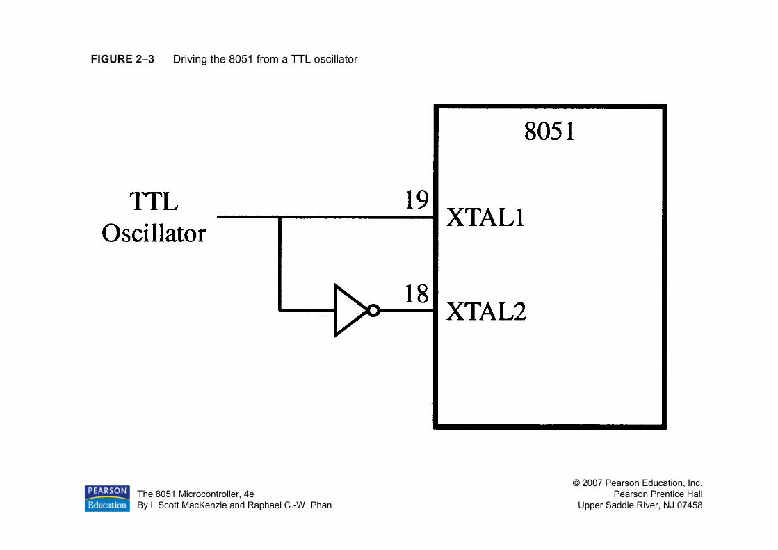
FIGURE 2–3 Driving the 8051 from a TTL oscillator

The 8051 Microcontroller, 4e
By I. Scott MacKenzie and Raphael C.-W. Phan
© 2007 Pearson Education, Inc.
Pearson Prentice Hall
Upper Saddle River, NJ 07458
FIGURE 2–4 Circuitry for I/O ports

The 8051 Microcontroller, 4e
By I. Scott MacKenzie and Raphael C.-W. Phan
© 2007 Pearson Education, Inc.
Pearson Prentice Hall
Upper Saddle River, NJ 07458
FIGURE 2–5 Relationship between oscillator clock cycles, states, and the machine cycle

The 8051 Microcontroller, 4e
By I. Scott MacKenzie and Raphael C.-W. Phan
© 2007 Pearson Education, Inc.
Pearson Prentice Hall
Upper Saddle River, NJ 07458
FIGURE 2–6 Summary of the 8031 memory spaces
The 8051 Microcontroller, 4e
By I. Scott MacKenzie and Raphael C.-W. Phan
© 2007 Pearson Education, Inc.
Pearson Prentice Hall
Upper Saddle River, NJ 07458
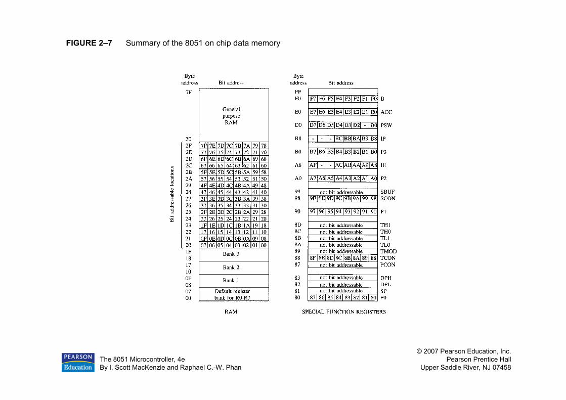
FIGURE 2–7 Summary of the 8051 on chip data memory
The 8051 Microcontroller, 4e
By I. Scott MacKenzie and Raphael C.-W. Phan
© 2007 Pearson Education, Inc.
Pearson Prentice Hall
Upper Saddle River, NJ 07458
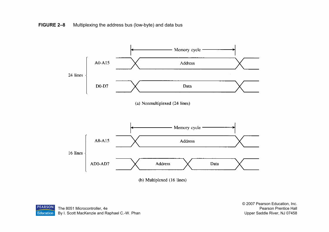
FIGURE 2–8 Multiplexing the address bus (low-byte) and data bus

The 8051 Microcontroller, 4e
By I. Scott MacKenzie and Raphael C.-W. Phan
© 2007 Pearson Education, Inc.
Pearson Prentice Hall
Upper Saddle River, NJ 07458
FIGURE 2–9 Accessing external code memory

The 8051 Microcontroller, 4e
By I. Scott MacKenzie and Raphael C.-W. Phan
© 2007 Pearson Education, Inc.
Pearson Prentice Hall
Upper Saddle River, NJ 07458
FIGURE 2–10 Read timing for external code memory

The 8051 Microcontroller, 4e
By I. Scott MacKenzie and Raphael C.-W. Phan
© 2007 Pearson Education, Inc.
Pearson Prentice Hall
Upper Saddle River, NJ 07458
FIGURE 2–11 Timing for MOVX instruction

The 8051 Microcontroller, 4e
By I. Scott MacKenzie and Raphael C.-W. Phan
© 2007 Pearson Education, Inc.
Pearson Prentice Hall
Upper Saddle River, NJ 07458
FIGURE 2–12 Interface to 1K RAM
The 8051 Microcontroller, 4e
By I. Scott MacKenzie and Raphael C.-W. Phan
© 2007 Pearson Education, Inc.
Pearson Prentice Hall
Upper Saddle River, NJ 07458
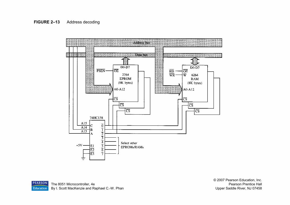
FIGURE 2–13 Address decoding

The 8051 Microcontroller, 4e
By I. Scott MacKenzie and Raphael C.-W. Phan
© 2007 Pearson Education, Inc.
Pearson Prentice Hall
Upper Saddle River, NJ 07458
FIGURE 2–14 Overlapping the external code and data spaces

The 8051 Microcontroller, 4e
By I. Scott MacKenzie and Raphael C.-W. Phan
© 2007 Pearson Education, Inc.
Pearson Prentice Hall
Upper Saddle River, NJ 07458
FIGURE 2–15 8032/52 memory spaces

The 8051 Microcontroller, 4e
By I. Scott MacKenzie and Raphael C.-W. Phan
© 2007 Pearson Education, Inc.
Pearson Prentice Hall
Upper Saddle River, NJ 07458
FIGURE 2–16 Two circuits for system reset. (a) Manual reset (b) Power-on reset.