FieldShield - Clearfield | Fiber Optic Products and ... FieldShield Aerial/Strand Mount Brac ket...
38
FieldShield Optical Fiber Protection System Installation Manual Multiport SmarTerminal Part #: 016164 Rev: D Updated: 8.2017 7050 Winnetka Ave N. Minneapolis, MN 55428 Direct: 763.476.6866 National: 800.422.2537 www.ClearfieldConnection.com [email protected]
Transcript of FieldShield - Clearfield | Fiber Optic Products and ... FieldShield Aerial/Strand Mount Brac ket...
FieldShield Optical Fiber Protection System
Installation Manual
Multiport SmarTerminal
Part #: 016164 Rev: D Updated: 8.2017 7050 Winnetka Ave N. Minneapolis, MN 55428 Direct: 763.476.6866 National: 800.422.2537 www.ClearfieldConnection.com [email protected]

2 Part Number: 016164
Table of Contents Introduction ........................................................................................................................3 Proprietary Notice ..............................................................................................................3 Technical Support ..............................................................................................................4 Standard Warranty .............................................................................................................5
Warranty Claim Procedure .............................................................................5 Limitations of Warranty ..................................................................................5 Other Limitations ............................................................................................5
FieldShield Product Overview ............................................................................................6 FieldShield Multiport SmarTerminal ...............................................................6 Universal Mounting Brackets .........................................................................7 Accessories ....................................................................................................8
Patch Only ..........................................................................................................................10 Feeder Fiber Installation ................................................................................10 Splicing SC Connectors .................................................................................11 SC Connector – Fiber Color Code Diagram ..................................................11 Dual LC Connector – Fiber Color Code Diagram ..........................................12
Patch and Splice ................................................................................................................13 FieldShield Cable Preparation .......................................................................13 Flat Drop and OSP Cable Preparation ..........................................................17 Ribbon Splicing ..............................................................................................20 Loose Tube Splicing.......................................................................................23 SmarTerminal Cover Installation ...................................................................26
Drop Cable Installation .......................................................................................................27 Preparing Drop Cable for Deploy Reel ..........................................................27
Single Cable Hardened Connector Installation ..................................................................29 Dual Cable (Y-Adapter) Hardened Connector Installation ................................................30 Sealing the Microduct ........................................................................................................32
Method #1 – Using Heatshrink for 8mm and 10mm Microduct .....................32 Method #2 – RTV Silicone .............................................................................32
Aerial/Strand Mount Bracket Installation............................................................................33 Aerial Shroud Installation ...................................................................................................34 Below Grade Flower Pot Installation ..................................................................................35 BD5 Pedestal Installation ...................................................................................................37

3 Part Number: 016164
Proprietary Notice About FieldShield Product Line Application Information contained in this document is copyrighted by Clearfield, Inc. and may not be duplicated in full or part by any person without prior written approval of Clearfield, Inc. Its purpose is to provide the user with adequately detailed documentation to efficiently install the equipment supplied. Every effort has been made to keep the information contained in this document current and accurate as of the date of publication or revision. However, no guarantee is given or implied that the document is error free or that it is accurate with regard to any specification.

4 Part Number: 016164
Technical Support Clearfield, Inc. can be contacted for any issues that arise with the supplied product. If you need to return the supplied product, you must contact the Clearfield, Inc. Customer Service Department to request a Returned Materials Authorization (RMA) number. Clearfield, Inc. 7050 Winnetka Ave N. Minneapolis, MN 55428 Toll Free: 800.422.2537 Phone: 763.476.6866 Fax: 763.475.8457 Customer Support: [email protected] Technical Support: [email protected]

5 Part Number: 016164
Standard Warranty Clearfield warrants to the original purchaser of the Product sold hereunder is free from defects in material and workmanship under normal use and service, subject to exceptions stated herein. Product purchased is warranted as follows: Clearfield designed and branded Products are warranted for five (5) years: Products manufactured by Clearfield to customer prints and/or specifications are warranted for one (1) year; and any Product Clearfield acquires from or through a third-party manufacturer or distributor and resells to Customer as the original customer will carry the manufacturer's pass-through warranty, if any. In all cases, the warranty period commences on the date of shipment to the original purchaser. Warranty Claim Procedure If any Product purchased from Clearfield is found defective under the above warranty, the following basic procedure must be followed:
1) Customer must contact Clearfield and obtain a Return Materials Authorization 2) Following authorization, the Customer ships the product-freight collect-to Clearfield’s
manufacturing facility 3) Clearfield shall repair or replace the defective Product at its sole option and discretion,
and return the repaired or replacement Product to Customer's site, freight prepaid
Note: If the Product is not found to be defective at Clearfield, the product will be returned to the Customer and the customer billed for freight in both directions. Limitations of Warranty Correction of defects by repair or replacement, at the option of Clearfield Inc, shall constitute the exclusive sole remedy for a breach of this limited warranty. Clearfield shall not be liable under any circumstances for any special, consequential, incidental, punitive, or exemplary damages arising out of or in any way connected with the product or with agreement to sell product to buyer, including, but not limited to damages for lost profits, loss of use, or for any damages or sums paid by buyer to third parties. The foregoing limitation of liability shall apply whether the claim is based upon principles of contract, warranty, negligence or other tort, breach of statutory duty, principles of indemnity or contribution, the failure of any limited or exclusive remedy to achieve its essential purpose, or otherwise. Clearfield will not be responsible for any labor or materials costs associated with installation or incorporation of Clearfield products at customer sites, including any costs of alteration, replacement or defective product, or any field repairs. Other Limitations Clearfield assumes no warranty liability regarding defects caused by:
1) Customer’s modification of Product, excepting installation activities described in Clearfield documentation
2) Customer re-packaging of Product for shipment to third parties or destinations other than those originally shipped to by Clearfield, or any defects suffered during shipping where the Product has been re-packaged
3) Customer’s installation or maintenance, excepting activities described in and performed in accordance with Clearfield documentation
4) Customer’s improper or negligent use or application of Product
Other causes external to the Product, including but not limited to accidents, catastrophe, acts of God, government action, war, riot, strikes, civil commotion, sovereign conduct, or the acts or conduct of any person or persons not party to or associated with Clearfield
6 Part Number: 016164
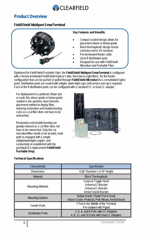
Product Overview FieldShield Multiport SmarTerminal
Key Features and Benefits • Compact sealed design allows for
placement above or below grade • Black thermoplastic design resists
corrosion and is UV resistant • Pre-terminated feeder cable • Up to 8 distribution ports • Designed for use with FieldShield
Microduct and Pushable Fiber Optimized for FieldShield Pushable Fiber, the FieldShield Multiport SmarTerminal is configured with a factory terminated FieldShield Optical Cable, from two to eight fibers, for the feeder configuration that can be pushed or pulled through FieldShield Microduct to a consolidated splice point. Distribution ports are sealed with airtight, water-tight caps until service turn-up is required. Each of the 8 distribution ports can be configured with a standard SC or Dual LC adapter.
For deployment in a pedestal, flower pot or vault, this above grade or below grade solution is the quickest, least intrusive placement method to deploy fiber, reducing restoration and troubleshooting costs as a cut fiber does not have to be retrenched. Restoration and troubleshooting are greatly reduced as a cut fiber does not have to be retrenched. Only the cut microduct/fiber needs to be located, route path re-engaged with a simple airtight/watertight coupler, and connectivity re-established with the push/pull of a replacement FieldShield Pushable Drop.
Technical Specifications
Characteristic Specification Dimensions 6.06" Diameter x 4.74" Height
Material Black Thermoplastic
Mounting Methods Snap-on Toggle Head Universal Z-Bracket Universal L-Bracket
Aerial Strand Bracket
Mounting Options Below Grade: Flower Pot or Vault Above Grade: Pedestal, Pole Mount, Aerial/Strand
Feeder Ports 1 Port in the Middle of the Terminal Pre-stubbed with Pigtail
Distribution Ports 2, 4, 6, and 8 Ports with SC Adapters 4, 8, 12, and 16 Ports with Dual LC Adapters
7 Part Number: 016164
Connectors SC/UPC, SC/APC, Dual LC/UPC, Dual LC/APC Universal Mounting Brackets
Key Features and Benefits
• Allows the SmarTerminal to be deployed inside any above grade or below grade enclosure
• Manufactured using Marine Grade Stainless Steel to withstand the harshest environments
• Powder coated black for additional protection
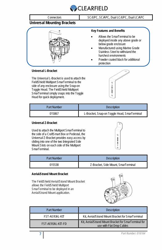
Universal L-Bracket The Universal L-Bracket is used to attach the FieldShield Multiport SmarTerminal to the side of any enclosure using the Snap-on Toggle Head. The FieldShield Multiport SmarTerminal simply snaps into the Toggle Head for quick deployment.
Part Number Description
015867 L-Bracket, Snap-on Toggle Head, SmarTerminal
Universal Z-Bracket Used to attach the Multiport SmarTerminal to the side of a CraftSmart Box or Pedestal, the Universal Z-Bracket provides easy access by sliding into one of the two Integrated Side Mount Slots on each side of the Multiport SmarTerminal.
Part Number Description
015538 Z-Bracket, Side Mount, SmarTerminal
Aerial/Strand Mount Bracket The FieldShield Aerial/Strand Mount Bracket allows the FieldShield Multiport SmarTerminal to be deployed in an Aerial/Strand Mount application.
Part Number Description
FST-AERIAL-KIT Kit, Aerial/Strand Mount Bracket for SmarTerminal
FST-AERIAL-KIT-FD Kit, Aerial/Strand Mount Bracket for SmarTerminal for use with Flat Drop Cables

8 Part Number: 016164
FST-AERIAL-ADP-KIT-10-8 Kit, For Adapting 10mm to 8mm Microduct, Includes 9 8” 10mm Black Ducts and 9 8mm to 10mm Couplers
Accessories
Hardened Pushable Connector Dust Cap The Hardened Connector Dust Cap is used to protect Hardened Pushable Connectors from OSP environments when installed prior to SmarTerminal deployment.
Part Number Description
FST-DUST-CAP Dust Cap, For Hardened Pushable Connectors
Single Cable Hardened Pushable Connectors The Single Cable Hardened Pushable Connector Kit provides a weather tight outer housing for FieldShield Pushable Assemblies and connects to either the FieldShield SmarTerminal or Hardened Pushable Bulkhead Adapter.
Components: • Connector Collar • Connector Housing
• Connector Split Grommet • Connector O-Ring
Part Number Description
FST-HARDENED-CONN-KIT Kit, Hardened Pushable Connector for 3mm FieldShield Cable, Single Cable 3mm Grommet
FST-HARDENED-CONN-KIT-4MM Kit, Hardened Pushable Connector for 4mm FieldShield Cable, Single Cable 4mm Grommet
Dual Cable (Y-Adapter) Hardened Pushable Connector The FieldShield Dual Cable Hardened Pushable Connector provides the components to distribute two separate LC simplex drop cables directly from a single port on the FieldShield SmarTerminal or the Y-Adapter Bulkhead Adapter Kit.
Components: • Connector Dual Cable Collar • Connector Dual Cable Housing
• Connector Dual Cable Split Grommet • Connector O-Ring
Part Number Description
FST-HRD-CON-KIT-3MM-2X Kit, Hardened Pushable Connector for 3mm FieldShield Cable, Dual Cable 3mm Grommet
9 Part Number: 016164
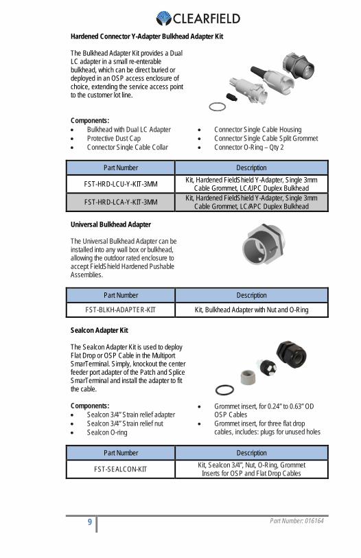
Hardened Connector Y-Adapter Bulkhead Adapter Kit The Bulkhead Adapter Kit provides a Dual LC adapter in a small re-enterable bulkhead, which can be direct buried or deployed in an OSP access enclosure of choice, extending the service access point to the customer lot line.
Components: • Bulkhead with Dual LC Adapter • Protective Dust Cap • Connector Single Cable Collar
• Connector Single Cable Housing • Connector Single Cable Split Grommet • Connector O-Ring – Qty 2
Part Number Description
FST-HRD-LCU-Y-KIT-3MM Kit, Hardened FieldShield Y-Adapter, Single 3mm Cable Grommet, LC/UPC Duplex Bulkhead
FST-HRD-LCA-Y-KIT-3MM Kit, Hardened FieldShield Y-Adapter, Single 3mm Cable Grommet, LC/APC Duplex Bulkhead
Universal Bulkhead Adapter The Universal Bulkhead Adapter can be installed into any wall box or bulkhead, allowing the outdoor rated enclosure to accept FieldShield Hardened Pushable Assemblies.
Part Number Description
FST-BLKH-ADAPTER-KIT Kit, Bulkhead Adapter with Nut and O-Ring
Sealcon Adapter Kit The Sealcon Adapter Kit is used to deploy Flat Drop or OSP Cable in the Multiport SmarTerminal. Simply, knockout the center feeder port adapter of the Patch and Splice SmarTerminal and install the adapter to fit the cable.
Components: • Sealcon 3/4” Strain relief adapter • Sealcon 3/4” Strain relief nut • Sealcon O-ring
• Grommet insert, for 0.24” to 0.63” OD OSP Cables
• Grommet insert, for three flat drop cables, includes: plugs for unused holes
Part Number Description
FST-SEALCON-KIT Kit, Sealcon 3/4”, Nut, O-Ring, Grommet Inserts for OSP and Flat Drop Cables
10 Part Number: 016164
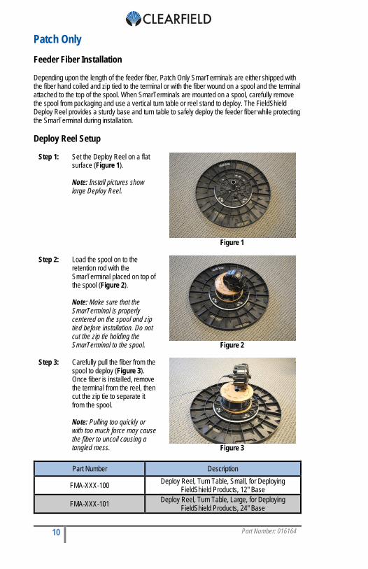
Patch Only Feeder Fiber Installation Depending upon the length of the feeder fiber, Patch Only SmarTerminals are either shipped with the fiber hand coiled and zip tied to the terminal or with the fiber wound on a spool and the terminal attached to the top of the spool. When SmarTerminals are mounted on a spool, carefully remove the spool from packaging and use a vertical turn table or reel stand to deploy. The FieldShield Deploy Reel provides a sturdy base and turn table to safely deploy the feeder fiber while protecting the SmarTerminal during installation. Deploy Reel Setup
Step 1: Set the Deploy Reel on a flat surface (Figure 1).
Note: Install pictures show
large Deploy Reel.
Figure 1
Step 2: Load the spool on to the
retention rod with the SmarTerminal placed on top of the spool (Figure 2).
Note: Make sure that the
SmarTerminal is properly centered on the spool and zip tied before installation. Do not cut the zip tie holding the SmarTerminal to the spool.
Figure 2
Step 3: Carefully pull the fiber from the
spool to deploy (Figure 3). Once fiber is installed, remove the terminal from the reel, then cut the zip tie to separate it from the spool.
Note: Pulling too quickly or
with too much force may cause the fiber to uncoil causing a tangled mess.
Figure 3
Part Number Description
FMA-XXX-100 Deploy Reel, Turn Table, Small, for Deploying FieldShield Products, 12" Base
FMA-XXX-101 Deploy Reel, Turn Table, Large, for Deploying FieldShield Products, 24" Base

11 Part Number: 016164
Splicing Feeder Cable Once the Patch Only SmarTerminal is placed in the housing of choice and the feeder fiber is pushed or pulled back to the consolidated splice point, splice the feeder cable.
Note: Do not remove the center hardened connector in attempt to access the feeder fiber. SC Connector – Fiber Color Code Diagram The ports of the SmarTerminal are configured to the following fiber color code diagram.
12 Part Number: 016164
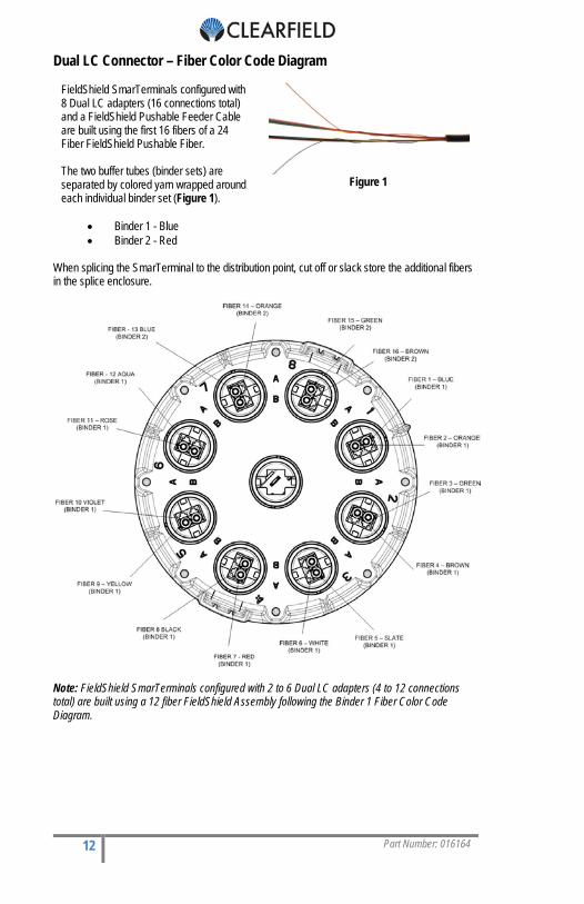
Dual LC Connector – Fiber Color Code Diagram
FieldShield SmarTerminals configured with 8 Dual LC adapters (16 connections total) and a FieldShield Pushable Feeder Cable are built using the first 16 fibers of a 24 Fiber FieldShield Pushable Fiber. The two buffer tubes (binder sets) are separated by colored yarn wrapped around each individual binder set (Figure 1).
• Binder 1 - Blue • Binder 2 - Red
Figure 1
When splicing the SmarTerminal to the distribution point, cut off or slack store the additional fibers in the splice enclosure.
Note: FieldShield SmarTerminals configured with 2 to 6 Dual LC adapters (4 to 12 connections total) are built using a 12 fiber FieldShield Assembly following the Binder 1 Fiber Color Code Diagram.
13 Part Number: 016164
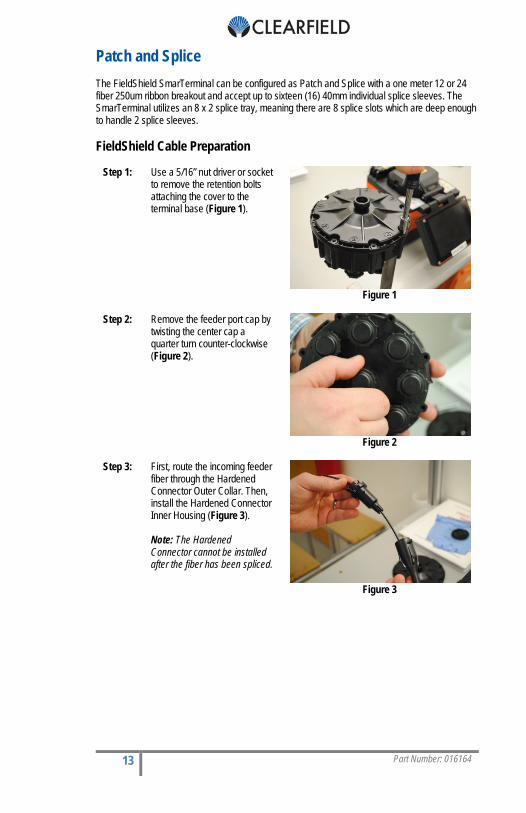
Patch and Splice The FieldShield SmarTerminal can be configured as Patch and Splice with a one meter 12 or 24 fiber 250um ribbon breakout and accept up to sixteen (16) 40mm individual splice sleeves. The SmarTerminal utilizes an 8 x 2 splice tray, meaning there are 8 splice slots which are deep enough to handle 2 splice sleeves. FieldShield Cable Preparation
Step 1: Use a 5/16” nut driver or socket to remove the retention bolts attaching the cover to the terminal base (Figure 1).
Figure 1
Step 2: Remove the feeder port cap by
twisting the center cap a quarter turn counter-clockwise (Figure 2).
Figure 2
Step 3: First, route the incoming feeder
fiber through the Hardened Connector Outer Collar. Then, install the Hardened Connector Inner Housing (Figure 3).
Note: The Hardened
Connector cannot be installed after the fiber has been spliced.
Figure 3

14 Part Number: 016164
Step 4: Route the FieldShield fiber into the center feeder port of the SmarTerminal, then push the Hardened Connector Inner Housing into the feeder port and secure by turning a quarter-turn clockwise (Figure 4).
Figure 4
Step 5 Pull the feeder cable through
the access hole in the center of the bulkhead (Figure 5).
Figure 5
Step 6: When applicable, tape down
fiber to the prepared work table (Figure 6).
Figure 6
Step 7: Measure and mark the jacket
of the feeder cable 36 inches from the end of the fiber (Figure 7).
Note: Clearfield recommends the removal of 36 inches of jacketing. The excess 250um is stored in the SmarTerminal. This provides extra fiber in case re-splicing is required.
Figure 7
15 Part Number: 016164
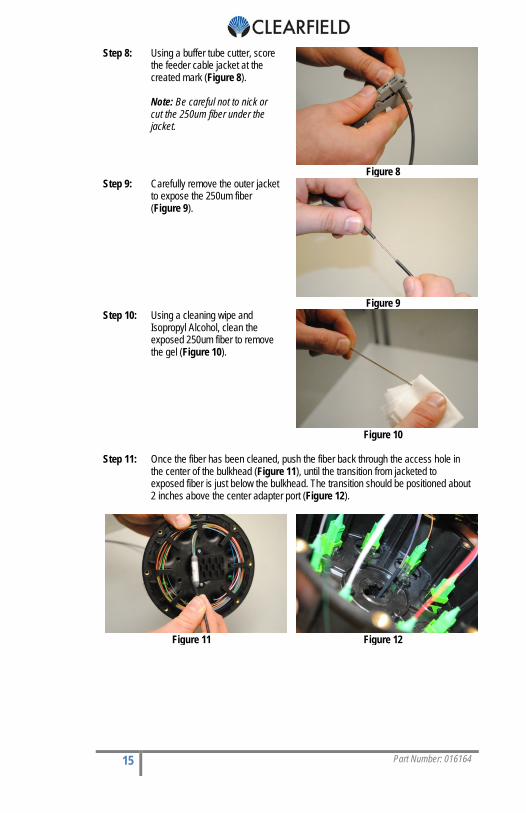
Step 8: Using a buffer tube cutter, score the feeder cable jacket at the created mark (Figure 8).
Note: Be careful not to nick or
cut the 250um fiber under the jacket.
Figure 8
Step 9: Carefully remove the outer jacket to expose the 250um fiber (Figure 9).
Figure 9
Step 10: Using a cleaning wipe and Isopropyl Alcohol, clean the exposed 250um fiber to remove the gel (Figure 10).
Figure 10
Step 11: Once the fiber has been cleaned, push the fiber back through the access hole in
the center of the bulkhead (Figure 11), until the transition from jacketed to exposed fiber is just below the bulkhead. The transition should be positioned about 2 inches above the center adapter port (Figure 12).
Figure 11
Figure 12

16 Part Number: 016164
Step 12: Slide the split grommet onto the cable (nipple end facing in) and push into the end of the Hardened Connector Inner Housing (Figure 13).
Figure 13
Note: Grommet should extend no more than 1/8th inch beyond the end of the Hardened Connector Inner Housing (Figure 14).
Figure 14
Step 13: Push the Hardened Connector
Outer Collar onto the Hardened Connector Inner Housing, lining up the pins and slots in the connector housings (Figure 15).
Quarter-turn clockwise to
secure the collar and lock the fiber into place.
Figure 15

17 Part Number: 016164
Flat Drop and OSP Cable Preparation
Step 1: Use a 5/16” nut driver or socket to remove the retention bolts attaching the cover to the terminal base (Figure 1).
Figure 1
Step 2: Remove the feeder port cap by
twisting the center cap a quarter turn counter-clockwise (Figure 2).
Figure 2
Step 3: While holding the base of the
terminal, carefully apply pressure to one side of the center feeder port using pliers until the center port snaps off at the knockout points (Figure 3).
Figure 3
Step 4: Score the inside of the
knockout with a razor blade to remove any burrs left in the material (Figure 4).
Note: Do not score beyond the
knockout. Removing too much material will jeopardize the integrity of the seal.
Figure 4

18 Part Number: 016164
Step 5: Insert the grommet into the Sealcon Adapter (Figure 5).
Grommet Inserts
• OSP Cable - 0.24” to 0.63” OD Insert
• Flat Drop - Three Cable Insert Includes plugs for unused holes
Figure 5
Step 6: Install the O-Ring onto the
Sealcon Adapter (Figure 6).
Figure 6
Step 7: Insert the 3/4” Sealcon Adapter
through the knockout (Figure 7).
Figure 7
Step 8: Use a 1-1/4” wrench to tighten
the retaining nut (Figure 8) on the inside of the SmarTerminal. Make sure to clasp the Sealcon Adapter while torquing the retaining nut.
Figure 8

19 Part Number: 016164
Step 10: Insert the incoming feeder fiber through the Sealcon Strain Relief Nut (Figure 9).
Figure 9
Step 10: Route the fiber through the
grommet insert in the center of the SmarTerminal and remove the buffer tube to expose 36” of fiber (Figure 10). Once the jacket has been removed, tighten the Strain Relief Nut to lock the cable into place.
Figure 10

20 Part Number: 016164
Ribbon Splicing
Step 1: Using a fiber arrangement tool, ribbonize the fiber per industry standard procedure (Figure 1).
Note: Make sure to place the
fibers in the fiber arrangement tool in the proper color coded order and to maintain even pressure on both the fiber and applicator when applying the adhesive.
Figure 1
Step 2: Remove a half loop of slack from the patch only ribbon breakout pigtail and reroute the fiber into the center of the splice tray (Figure 2).
Figure 2
Step 3: Route the ribbonized feeder fiber
clockwise under the slack storage tray into the splice tray (Figure 3).
Figure 3
Step 4: Trim the fibers to length (Figure
4).
Figure 4

21 Part Number: 016164
Step 5: Once the fiber is trimmed, pull the fiber out of the terminal. Take the feeder fiber (fiber pigtail that came in the SmarTerminal) and install the mass fusion splice sleeve (Figure 5). You are now ready to splice.
Note: Clearfield recommends
using 30mm long mass fusion splice sleeves.
Figure 5
Step 6: After the splicing following industry standard procedure, route the fiber counter-clockwise into the slack storage tray (Figure 6).
Figure 6
Step 7: Continue until the splice sleeve is
centered in the splice tray (Figure 7) all the slack is properly stored. Mark the location where the splice sleeve rests in the splice tray.
Figure 7
Step 8: Using a pair of needle nose pliers, twist the center splice tray sleeve retention clip
(Figure 8) to provide space for the mass fusion splice sleeve (Figure 9).
Figure 8
Figure 9
22 Part Number: 016164
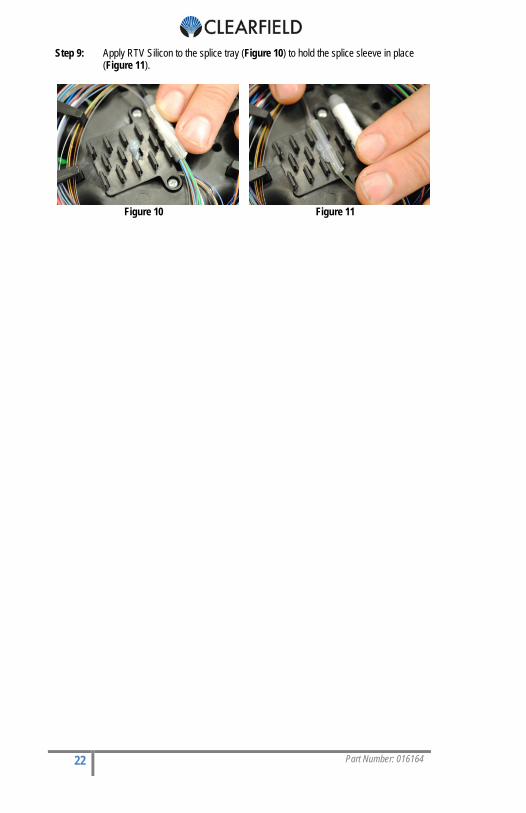
Step 9: Apply RTV Silicon to the splice tray (Figure 10) to hold the splice sleeve in place (Figure 11).
Figure 10
Figure 11
23 Part Number: 016164
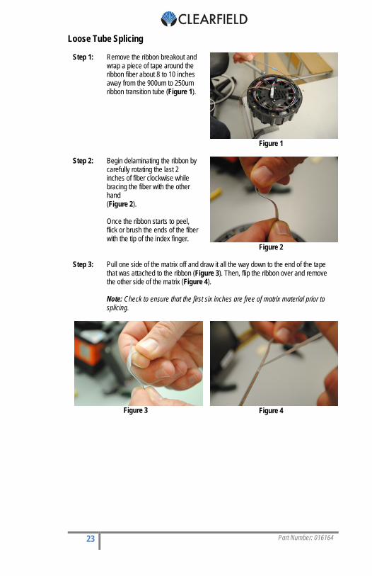
Loose Tube Splicing
Step 1: Remove the ribbon breakout and wrap a piece of tape around the ribbon fiber about 8 to 10 inches away from the 900um to 250um ribbon transition tube (Figure 1).
Figure 1
Step 2: Begin delaminating the ribbon by
carefully rotating the last 2 inches of fiber clockwise while bracing the fiber with the other hand (Figure 2).
Once the ribbon starts to peel,
flick or brush the ends of the fiber with the tip of the index finger.
Figure 2
Step 3: Pull one side of the matrix off and draw it all the way down to the end of the tape that was attached to the ribbon (Figure 3). Then, flip the ribbon over and remove the other side of the matrix (Figure 4).
Note: Check to ensure that the first six inches are free of matrix material prior to
splicing.
Figure 3
Figure 4

24 Part Number: 016164
Step 4: Starting at the transition tube, route the delaminated pigtail counter-clockwise into the slack storage tray until there is not enough fiber to complete another slack loop. Then, route the fiber into the center of the splice try (Figure 5).
Note: Make sure to route the fiber
underneath the retention tabs of the slack storage tray.
Figure 5
Step 5: Route the feeder fiber clockwise
under the slack storage tray into the splice tray (Figure 6).
Figure 6
Step 6: Trim the fibers to length
(Figure 7).
Figure 7
Step 7: Take the first fiber from both sides,
and splice per recommend industry standard and splice machine guidelines (Figure 8).
Note: While waiting for your first
splice sleeve to cool, start prepping your second fiber and continue with splicing.
Figure 8
25 Part Number: 016164
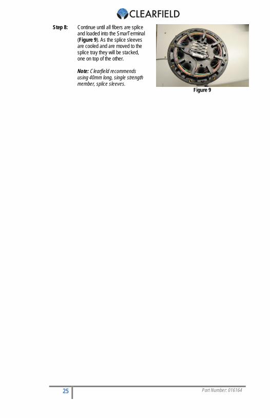
Step 8: Continue until all fibers are splice and loaded into the SmarTerminal (Figure 9). As the splice sleeves are cooled and are moved to the splice tray they will be stacked, one on top of the other.
Note: Clearfield recommends
using 40mm long, single strength member, splice sleeves.
Figure 9

26 Part Number: 016164
SmarTerminal Cover Installation
Step 1: Install the gasket (located in the ship-along plastic bag tapped to cover of the Patch and Splice SmarTerminal) into the gasket seam at the top of the terminal base (Figure 1).
Figure 1
Step 2: Place the cover onto the base of
the terminal. Make sure to align the triangle indicator on port 1 of the cover with port 1 of the base to ensure proper port identification (Figure 2).
Figure 2
.Step 3: Following the recommended torque pattern (Figure 3), use a 5/16” nut driver or socket
to install the retention bolts attaching the cover to the base of the terminal (Figure 4). Once all bolts have been installed, torque each bolt an additional quarter-turn following the same torque pattern.
Note: When a torque wrench is available, the bolts should be torque to approximately
13 ft lbs.
Figure 3
Figure 4

27 Part Number: 016164
Drop Cable Installation Packaging
Note: Eight (8) spools placed in a 16” W x 16” D x 8’’ H box. Preparing Drop Cable for Deploy Reel
Step 1: FieldShield Drop Cables with the Hardened Connector preinstalled need the Hardened Connector rerouted to the top of the spool before deploying (Figure 1).
Figure 1
Step 2: Carefully remove the tape
holding the Hardened Connector to the inside flange of the spool (Figure 2).
Figure 2
28 Part Number: 016164
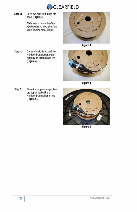
Step 3: Feed two zip ties through the spool (Figure 3).
Note: Make sure to feed the
zip tie between the side of the spool and the inner flange.
Figure 3
Step 4: Center the zip tie around the
Hardened Connector, then tighten and trim both zip ties (Figure 4).
Figure 4
Step 5: Place the drop cable spool on
the deploy reel with the Hardened Connector on top (Figure 5).
Figure 5
29 Part Number: 016164
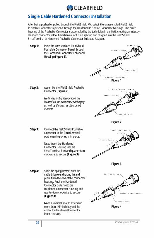
Single Cable Hardened Connector Installation After being pushed or pulled through the FieldShield Microduct, the unassembled FieldShield Pushable Connector is pushed through the Hardened Pushable Connector housings. The outer housing of the Pushable Connector is assembled by the technician in the field, creating an industry standard connector without mechanical or fusion splicing and plugged into the FieldShield SmarTerminal or Hardened Pushable Connector Bulkhead Adapter.
Step 1: Push the unassembled FieldShield Pushable Connector Barrel through the Hardened Connector Collar and Housing (Figure 1).
Figure 1
Step 2: Assemble the FieldShield Pushable
Connector (Figure 2). Note: Assembly instructions are
located on the connector packaging as well as the next section of this manual.
Figure 2
Step 3: Connect the FieldShield Pushable
Connector to the SmarTerminal port, ensuring o-ring is in place.
Next, insert the Hardened
Connector Housing into the SmarTerminal Port and quarter-turn clockwise to secure (Figure 3).
Figure 3
Step 4: Slide the split grommet onto the
cable (nipple end facing in) and push it into the end of the connector housing. Push the Hardened Connector Collar onto the Hardened Connector Housing and quarter-turn clockwise to secure (Figure 4).
Note: Grommet should extend no
more than 1/8th inch beyond the end of the Hardened Connector Inner Housing.
Figure 4
30 Part Number: 016164
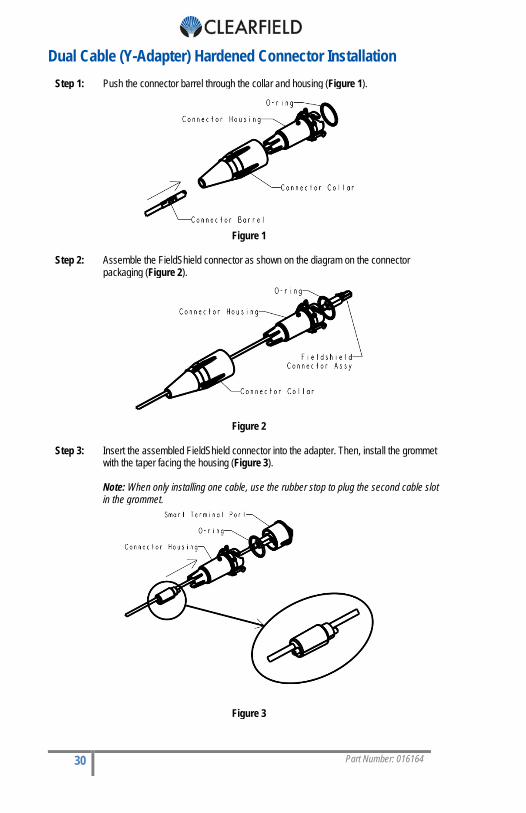
Dual Cable (Y-Adapter) Hardened Connector Installation
Step 1: Push the connector barrel through the collar and housing (Figure 1).
Figure 1
Step 2: Assemble the FieldShield connector as shown on the diagram on the connector
packaging (Figure 2).
Figure 2
Step 3: Insert the assembled FieldShield connector into the adapter. Then, install the grommet
with the taper facing the housing (Figure 3). Note: When only installing one cable, use the rubber stop to plug the second cable slot
in the grommet.
Figure 3

31 Part Number: 016164
Step 4: Push the second connector barrel through the collar and housing (Figure 4).
Figure 4
Step 5: Assemble the connector and insert into the available adapter port. Then, slide the cable
into the split grommet, ensuring o-ring is in place. (Figure 5). Note: When installing the second cable remove the plug from the grommet.
Figure 5
Step 6: Push the hardened connector housing into the SmarTerminal Port and quarter-turn
clockwise to secure. Once the housing is installed, slide the split grommet into the housing. Then, push the
collar onto the housing and quarter-turn clockwise. (Figure 6). Note: Grommet should extend no more than 1/8th inch beyond the end of the Hardened
Connector Inner Housing.
Figure 6

32 Part Number: 016164
Sealing the Microduct
Once the fiber has been pushed or pulled through the microduct, certain applications require the inner bore of the conduit be sealed. When using direct bury toneable microducts it is recommended to seal the duct to keep moisture, dirt, and other debris out of the microduct.
Also, some splice cases require the enclosure to be pressurized when sealed. The end of the duct must be sealed to prevent air from escaping because the microduct acts as a long tube, allowing the air to be release from the other side. Note: End Caps and End Plugs should be used to seal the microduct until the fiber is installed. Method #1 – Using Heatshrink for 8mm and 10mm Microduct
Step 1: Center a 4 inch section of 3:1 shrink ratio 3/8” ID gel lined heatshrink over the FieldShield microduct and fiber. Leave approximately 2 inches of heatshrink over both the microduct and fiber (Figure 1).
Figure 1
Step 2: Use a heat source to evenly heat the heatshrink. Heat from the end of the heatshrink covering the microduct and slowly work towards the fiber.
Note: To achieve the best seal, rotate the heat source around the heatshrink in a
spiral path. A little bit of epoxy should seep out of both ends of the heatshrink if the gel is properly heated.
Part Number Description
FS-CBL-DCT-SEAL-10MM Tubing, Heatshrink, Black, 3/8” Dual Wall Epoxy Lined, Cut to 4 Inches
Method #2 – RTV Silicone
Step 1: After the fiber has been installed, fill the end of microduct with RTV Silicone. Make sure to fill approximately ½” to 1” of duct.
Step 2: Wipe away excess RTV Silicone
and allow RTV to dry (Figure 2). Note: In the event of a later
repair, remove the damaged assembly by cutting 1 inch from the end of the duct, then install a new FieldShield Assembly.
Figure 2
33 Part Number: 016164
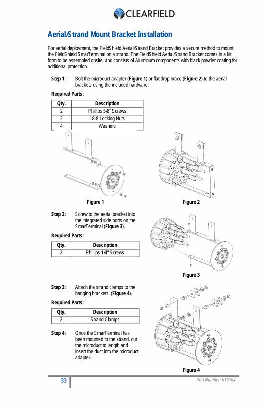
Aerial/Strand Mount Bracket Installation For aerial deployment, the FieldShield Aerial/Strand Bracket provides a secure method to mount the FieldShield SmarTerminal on a strand. The FieldShield Aerial/Strand Bracket comes in a kit form to be assembled onsite, and consists of Aluminum components with black powder coating for additional protection.
Step 1: Bolt the microduct adapter (Figure 1) or flat drop brace (Figure 2) to the aerial brackets using the included hardware.
Required Parts:
Qty. Description 2 Phillips 5/8” Screws 2 18-8 Locking Nuts 4 Washers
Figure 1
Figure 2
Step 2: Screw to the aerial bracket into the integrated side ports on the SmarTerminal (Figure 3).
Required Parts:
Qty. Description 2 Phillips 1/4” Screws
Figure 3
Step 3: Attach the strand clamps to the
hanging brackets. (Figure 4).
Required Parts:
Qty. Description 2 Strand Clamps
Step 4: Once the SmarTerminal has
been mounted to the strand, cut the microduct to length and insert the duct into the microduct adapter.
Figure 4
34 Part Number: 016164
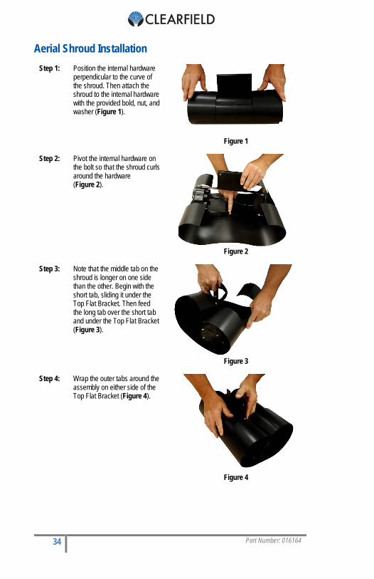
Aerial Shroud Installation
Step 1: Position the internal hardware perpendicular to the curve of the shroud. Then attach the shroud to the internal hardware with the provided bold, nut, and washer (Figure 1).
Figure 1
Step 2: Pivot the internal hardware on
the bolt so that the shroud curls around the hardware (Figure 2).
Figure 2
Step 3: Note that the middle tab on the
shroud is longer on one side than the other. Begin with the short tab, sliding it under the Top Flat Bracket. Then feed the long tab over the short tab and under the Top Flat Bracket (Figure 3).
Figure 3
Step 4: Wrap the outer tabs around the
assembly on either side of the Top Flat Bracket (Figure 4).
Figure 4

35 Part Number: 016164
Below Grade Flower Pot Installation
Part Number Description
012556 Washer, Flat, #10, 3/4” OD, 0.05” Thick, 18-8 SST
016620 Screw, Pan Head, Phillips, 10-24 x 1-3/4”, SST
Step 1: When using toneable microduct, install the ground bar on the inside of the enclosure before burying the flower pot in the ground (Figure 1).
Note: Since there are many
different standards/requirements for grounding - BISCI, NEC, Moto R-56 etc, Clearfield adheres to the principle that the all grounding installations follow the "per local practice" guidelines for each application.
Figure 1
Part Number Description
FST-GND-BAR-KIT Kit, Ground Bar, Ground Lug, and Mounting
Hardware, For Use in Flower Pots and Vaults For SmarTerminal
Step 2: When using the snap on toggle
head to mount the terminal, drill a 5/32 hole in the center of the flower pot lid (Figure 2).
Place a flat washer between
the screw head and the lid and tighten the screw into the snap on toggle head.
For Pencell flower pots use the
1 ¾” screw included with the SmarTerminal. When using a Channell flower pot use a 1” 10-24 screw.
Note: For other options, the
screw should be ½” longer than the thickness of the top/lid material
Figure 2

36 Part Number: 016164
Step 3: Route the microduct under the base of the flower pot (Figure 3).
Note: When using toneable
microduct, ground per local practice.
Figure 3
Step 4: Once the fiber has been
installed in the microduct, coil the feeder and drop cable slack inside the base of the flower pot (Figure 4).
Figure 4
Step 5: Zip tie or electrical tape the
coils so that the distance between each coil and the SmarTerminal is the same (Figure 5).
Note: This will make the slack
easier to control when accessing the terminal.
Figure 5

37 Part Number: 016164
BD5 Pedestal Installation
Step 1: Use the existing knockout holes towards the top of the BD5 pedestal or drill two holes in the desired mounting location (Figure 1).
Figure 1
Step 2: Bolting from the outside, attach
the universal mounting bracket to pedestal (Figure 2).
Figure 2
Step 3: When using the Universal L-
Bracket, screw the Snap-On Toggle Head into the mounting hole located on the top of the bracket (Figure 3).
Figure 3
Step 4: Bundle and zip tie the
microducts to the cable tie off towards the bottom of the pedestal. When using toneable microduct, make sure to ground the tone wire to the grounding bar following company procedure (Figure 4).
Note: If the drop cable is not
being installed until a later date, secure the pull string to the microduct then cap the duct.
Figure 4

38 Part Number: 016164
Step 5: Slack store the drop cables and feeder fiber to the pedestal using zip-ties and cable tie offs inserted into the pedestal backplane (Figure 5).
Note: Seal the microduct after
installing the fiber. When using heatshrink, make sure to pre-place the heatshrink around the microduct before inserting the cable into the duct.
Figure 5
Step 6: When deploying Patch and
Splice SmarTerminals, it is recommended to use the Universal Z-Bracket to hold the SmarTerminal in an upright position when splicing. (Figure 6).
Note: This allows a splice table
to be setup at the pedestal.
Figure 6