Fieldbus Independent I/O Modules Incremental Encoder ... · PDF fileI/O Modules Incremental...
64
Fieldbus Independent I/O Modules Incremental Encoder Interfaces 750-637, (/xxx-xxx) Manual Version 1.4.0
Transcript of Fieldbus Independent I/O Modules Incremental Encoder ... · PDF fileI/O Modules Incremental...

Fieldbus Independent I/O Modules
Incremental Encoder Interfaces 750-637, (/xxx-xxx)
Manual
Version 1.4.0

ii • General
WAGO-I/O-SYSTEM 750 I/O Modules
Copyright 2008 by WAGO Kontakttechnik GmbH & Co. KG All rights reserved.
WAGO Kontakttechnik GmbH & Co. KG Hansastraße 27 D-32423 Minden
Phone: +49 (0) 571/8 87 – 0 Fax: +49 (0) 571/8 87 – 1 69
E-Mail: [email protected]
Web: http://www.wago.com
Technical Support Phone: +49 (0) 571/8 87 – 5 55 Fax: +49 (0) 571/8 87 – 85 55
E-Mail: [email protected]
Every conceivable measure has been taken to ensure the correctness and com-pleteness of this documentation. However, as errors can never be fully excluded, we would appreciate any information or ideas at any time.
E-Mail: [email protected]
We wish to point out that the software and hardware terms as well as the trademarks of companies used and/or mentioned in the present manual are generally trademark or patent protected.

Contents • iii
WAGO-I/O-SYSTEM 750 I/O Modules
Contents
1 Important Notes .......................................................................................... 5 1.1 Legal Bases............................................................................................... 5 1.1.1 Copyright ............................................................................................. 5 1.1.2 Personnel Qualifications...................................................................... 5 1.1.3 Use of the 750 Series in Compliance with Underlying Provisions ..... 6 1.1.4 Technical Condition of Specified Devices .......................................... 6 1.2 Standards and Guidelines for Operating the 750 Series........................... 7 1.3 Symbols .................................................................................................... 8 1.4 Safety Information.................................................................................... 9 1.5 Font Conventions ................................................................................... 10 1.6 Number Notation.................................................................................... 10 1.7 Scope ........................................................................................................ 5
2 I/O Modules ............................................................................................... 11 2.1 Special Modules ..................................................................................... 11 2.1.1 Overview Incremental Encoder Interfaces 750-637, (/xxx-xxx)....... 11 2.1.2 750-637 [Inc.Enc./RS422/32Bit/Diff.] .............................................. 12 2.1.2.1 Variations...................................................................................... 12 2.1.2.2 View.............................................................................................. 12 2.1.2.3 Description.................................................................................... 12 2.1.2.4 Display Elements .......................................................................... 14 2.1.2.5 Schematic Diagram....................................................................... 14 2.1.2.6 Technical Data .............................................................................. 15 2.1.2.7 Functional Description.................................................................. 18 2.1.2.8 Process Image ............................................................................... 19 2.1.3 750-637/000-001 [Inc.Enc./24V/32Bit/Diff.].................................... 23 2.1.3.1 View.............................................................................................. 23 2.1.3.2 Description.................................................................................... 23 2.1.3.3 Display Elements .......................................................................... 25 2.1.3.4 Schematic Diagram....................................................................... 25 2.1.3.5 Technical Data .............................................................................. 26 2.1.3.6 Functional Description.................................................................. 28 2.1.3.7 Process Image ............................................................................... 29 2.1.4 750-637/000-002 [Inc.Enc./24V/32Bit/S.E.]..................................... 33 2.1.4.1 View.............................................................................................. 33 2.1.4.2 Description.................................................................................... 33 2.1.4.3 Display Elements .......................................................................... 35 2.1.4.4 Schematic Diagram....................................................................... 35 2.1.4.5 Technical Data .............................................................................. 36 2.1.4.6 Functional Description.................................................................. 38 2.1.4.7 Process Image ............................................................................... 39 2.1.5 750-637/000-004 [Inc.Enc./24V/32Bit/S.E./cam]............................. 43 2.1.5.1 View.............................................................................................. 43 2.1.5.2 Description.................................................................................... 43 2.1.5.3 Display Elements .......................................................................... 45 2.1.5.4 Schematic Diagram....................................................................... 45

iv • Contents
WAGO-I/O-SYSTEM 750 I/O Modules
2.1.5.5 Technical Data .............................................................................. 46 2.1.5.6 Functional Description..................................................................47 2.1.5.7 Process Image ............................................................................... 49
3 Use in Hazardous Environments .............................................................54 3.1 Identification .......................................................................................... 55 3.1.1 For Europe according to CENELEC and IEC ...................................55 3.1.2 For America according to NEC 500 .................................................. 58 3.2 Installation Regulations.......................................................................... 59 3.2.1 Special Conditions for Safe Operation of the ATEX and IEC Ex (acc.
DEMKO 08 ATEX 142851X and IECEx PTB 07.0064).................. 60 3.2.2 Special conditions for safe use (ATEX Certificate TÜV 07 ATEX
554086 X) .......................................................................................... 61 3.2.3 Special conditions for safe use (IEC-Ex Certificate TUN 09.0001 X)62 3.2.4 ANSI/ISA 12.12.01 ........................................................................... 63

Important Notes • 5
Legal Bases
WAGO-I/O-SYSTEM 750 I/O Modules
1 Important Notes
This section includes an overall summary of the most important safety requirements and notes that are mentioned in each individual section. To protect your health and prevent damage to devices as well, it is imperative to read and carefully follow the safety guidelines.
1.1 Legal Bases
1.1.1 Copyright
This Manual, including all figures and illustrations, is copyright-protected. Any further use of this Manual by third parties that violate pertinent copyright provisions is prohibited. Reproduction, translation, electronic and phototechnical filing/archiving (e.g., photocopying) as well as any amendments require the written consent of WAGO Kontakttechnik GmbH & Co. KG, Minden, Germany. Non-observance will involve the right to assert damage claims.
WAGO Kontakttechnik GmbH & Co. KG reserves the right to provide for any alterations or modifications that serve to increase the efficiency of technical progress. WAGO Kontakttechnik GmbH & Co. KG owns all rights arising from the granting of patents or from the legal protection of utility patents. Third-party products are always mentioned without any reference to patent rights. Thus, the existence of such rights cannot be excluded.
1.1.2 Personnel Qualifications
The use of the product described in this Manual requires special personnel qualifications, as shown in the following table:
Activity Electrical specialist Instructed personnel*)
Specialists**) having qualifications in PLC programming
Assembly X X
Commissioning X X
Programming X
Maintenance X X
Troubleshooting X
Disassembly X X
*) Instructed persons have been trained by qualified personnel or electrical specialists.
**) A specialist is a person, who – thanks to technical training – has the qualification, know- ledge and expertise to meet the required specifications of this work and to identify any po- tential hazardous situation in the above listed fields of activity.

6 • Important Notes
Legal Bases
WAGO-I/O-SYSTEM 750 I/O Modules
All responsible persons have to familiarize themselves with the underlying legal standards to be applied. WAGO Kontakttechnik GmbH & Co. KG does not assume any liability whatsoever resulting from improper handling and damage incurred to both WAGO´s own and third-party products by disregarding detailed information in this Manual.
1.1.3 Use of the 750 Series in Compliance with Underlying Provisions
Couplers, controllers and I/O modules found in the modular WAGO-I/O-SYSTEM 750 receive digital and analog signals from sensors and transmit them to the actuators or higher-level control systems. Using programmable controllers, the signals can also be (pre-)processed.
The components have been developed for use in an environment that meets the IP20 protection class criteria. Protection against finger injury and solid impurities up to 12.5 mm diameter is assured; protection against water damage is not ensured. Unless otherwise specified, operation of the components in wet and dusty environments is prohibited.
1.1.4 Technical Condition of Specified Devices
The components to be supplied Ex Works, are equipped with hardware and software configurations, which meet the individual application requirements. Changes in hardware, software and firmware are permitted exclusively within the framework of the various alternatives that are documented in the specific manuals. WAGO Kontakttechnik GmbH & Co. KG will be exempted from any liability in case of changes in hardware or software as well as to non-compliant usage of components.
Please send your request for modified and new hardware or software configurations directly to WAGO Kontakttechnik GmbH & Co. KG.

Important Notes • 7
Standards and Guidelines for Operating the 750 Series
WAGO-I/O-SYSTEM 750 I/O Modules
1.2 Standards and Guidelines for Operating the 750 Series
Please adhere to the standards and guidelines required for the use of your system:
The data and power lines shall be connected and installed in compliance with the standards required to avoid failures on your system and to substantially minimize any imminently hazardous situations resulting in personal injury.
For assembly, start-up, maintenance and troubleshooting, adhere to the specific accident prevention provisions which apply to your system (e.g. BGV A 3, "Electrical Installations and Equipment").
Emergency stop functions and equipment shall not be made ineffective. See relevant standards (e.g. DIN EN 418).
The equipment of your system shall be conform to EMC guidelines so that any electromagnetic interferences will be eliminated.
Operating 750 Series components in home applications without further measures is permitted only if they meet the emission limits (emissions of interference) in compliance with EN 61000-6-3. You will find the detailed information in section "WAGO-I/O-SYSTEM 750" "System Description" "Technical Data".
Please observe the safety precautions against electrostatic discharge in accordance with DIN EN 61340-5-1/-3. When handling the modules, please ensure that environmental factors (persons, working place and packaging) are well grounded.
The valid standards and guidelines applicable for the installation of switch cabinets shall be adhered to.

8 • Important Notes
Symbols
WAGO-I/O-SYSTEM 750 I/O Modules
1.3 Symbols
Danger Always observe this information to protect persons from injury.
Warning Always observe this information to prevent damage to the device.
Attention Marginal conditions that must always be observed to ensure smooth and efficient operation.
ESD (Electrostatic Discharge) Warning of damage to the components through electrostatic discharge. Observe the precautionary measure for handling components at risk of electrostatic discharge.
Note Make important notes that are to be complied with so that a trouble-free and efficient device operation can be guaranteed.
Additional Information References to additional literature, manuals, data sheets and internet pages.

Important Notes • 9
Safety Information
WAGO-I/O-SYSTEM 750 I/O Modules
1.4 Safety Information
When connecting the device to your installation and during operation, the following safety notes must be observed:
Danger The WAGO-I/O-SYSTEM 750 and its components are an open system. It must only be assembled in housings, cabinets or in electrical operation rooms. Access is only permitted via a key or tool to authorized qualified personnel.
Danger All power sources to the device must always be switched off before carrying out any installation, repair or maintenance work.
Warning Replace defective or damaged device/module (e.g. in the event of deformed contacts), as the functionality of field bus station in question can no longer be ensured on a long-term basis.
Warning The components are not resistant against materials having seeping and insulating properties. Belonging to this group of materials is: e.g. aerosols, silicones, triglycerides (found in some hand creams). If it cannot be ruled out that these materials appear in the component environment, then the components must be installed in an enclosure that is resistant against the above mentioned materials. Clean tools and materials are generally required to operate the device/module.
Warning Soiled contacts must be cleaned using oil-free compressed air or with ethyl alcohol and leather cloths.
Warning Do not use contact sprays, which could possibly impair the functioning of the contact area.
Warning Avoid reverse polarity of data and power lines, as this may damage the devices.
ESD (Electrostatic Discharge) The devices are equipped with electronic components that may be destroyed by electrostatic discharge when touched.

10 • Important Notes
Font Conventions
WAGO-I/O-SYSTEM 750 I/O Modules
Warning For components with ETHERNET/RJ-45 connectors: Only for use in LAN, not for connection to telecommunication circuits.
1.5 Font Conventions
italic Names of paths and data files are marked in italic-type. e.g.: C:\Programs\WAGO-IO-CHECK
italic Menu items are marked in italic-type, bold letters. e.g.: Save
\ A backslash between two names characterizes the selection of a menu point from a menu. e.g.: File \ New
END Pushbuttons are marked as bold with small capitals e.g.: ENTER
< > Keys are marked bold within angle brackets e.g.: <F5>
Courier The print font for program codes is Courier. e.g.: END_VAR
1.6 Number Notation
Number code Example Note
Decimal 100 Normal notation
Hexadecimal 0x64 C notation
Binary '100' '0110.0100'
In quotation marks, nibble separated with dots (.)
1.7 Scope
This manual describes the special modules 750-637, (/xxx-xxx) Incremental Encoder Interfaces of the modular WAGO-I/O-SYSTEM 750.
Handling, assembly and start-up are described in the manual of the Fieldbus Coupler. Therefore this documentation is valid only in the connection with the appropriate manual

Overview Incremental Encoder Interfaces 750-637, (/xxx-xxx) • 11
WAGO-I/O-SYSTEM 750 I/O Modules
2 I/O Modules
2.1 Special Modules
2.1.1 Overview Incremental Encoder Interfaces 750-637, (/xxx-xxx)
I/O Module 750-637 750-637/ 000-001
750-637/ 000-002
750-637/ 000-003
750-637/ 000-004
Function Incremental Encoder Interface
Incremental Encoder Interface
Incremental Encoder Interface
Incremental Encoder Interface
Incremental Encoder Interface
Input differential differential single ended
differential differential
Sensor Operation Voltage
DC 5 V DC 24 V DC 24 V DC 5 V DC 5 V
Interpretation fourfold fourfold fourfold single single
Bit Width 32 Bit 32 Bit 32 Bit 32 Bit 32 Bit

12 • 750-637 [Inc.Enc./RS422/32Bit/Diff.]
Variations
WAGO-I/O-SYSTEM 750 I/O Modules
2.1.2 750-637 [Inc.Enc./RS422/32Bit/Diff.]
Incremental encoder interface RS422 / 32 bit / differential
2.1.2.1 Variations
Item-No. Designation Description
750-637 Inc.Enc./RS422/32Bit/ Diff.
Incremental Encoder Interface RS422 / 32 Bit / differential / fourfold interpretation
750-637/000-003 Inc.Enc./RS422/32Bit/ Diff./Single Interpret.
Incremental Encoder Interface RS422 / 32 Bit / differential / single interpretation
2.1.2.2 View
+ -
L G
R S
15 16
C
D
B
A
C C
Ue Uo
13 14
C
D
B
A
750-637
B B
A A
N1 N2
C
AB
Latch
A
A
B
B
C
C
5V0V
GateLatch
N 2N 1
0V24V
N 1N 2GateRef
Ref
Data contacts
Shield (screen)Sensor supply
Fig. 2.1.2-1: View g063700e
2.1.2.3 Description
The I/O module 750-637 represents an interface for any type of incremental encoder with an RS 422 connection.
The data width of the encoder module is 32 bits. Either the current counter reading, the latch value, the set value or the current speed can be mapped into the process data.

750-637 [Inc.Enc./RS422/32Bit/Diff.] • 13
Description
WAGO-I/O-SYSTEM 750 I/O Modules
Inputs/Outputs
A, /A, B, /B Quadrature input, RS 422
C, /C Zero reference input, RS 422
Latch, Gate, Ref Input, 24 V
N1, N2 Output, 24 V
A counter with quadrature decoder and a latch for the zero pulse can be read and activated by the PLC. The PLC is able to set the counter. Depending on the operating mode, the counter reading is taken into the latch register, if the edge at input “C” or “Latch” is positive.
The speed (increments/ms) is automatically recorded and can be transmitted as an alternative to the latch value.
The „Gate” input allows to lock the counter. The „Ref” input can be set to activate the zero mark „C”.
The cam outputs N1 and N2 indicate whether the counter value is within a defined range of values. The range can be adjusted for each cam via the PLC. Starting with the software version XXXX03XX, the cam outputs can be disabled by the PLC and the states of the cam outputs can be queried.
24 V DC is required to supply the I/O modules, from this voltage also the voltage supply to the encoder (Ue, U0) is branched/tapped.
Attention This module has no power contacts. For field supply to downstream I/O modules, a supply module will be needed.
The shield (screen) is directly connected to the carrier rail.
The module 750-637 can be used with all couplers/controllers of the WAGO-I/O-SYSTEM 750 (except for the economy types 750-320, -323, -324 and -327).
The version of both hardware and software that are valid for this module is specified in the manufacturing number, which is part of the lateral marking on the module.

14 • 750-637 [Inc.Enc./RS422/32Bit/Diff.]
Display Elements
WAGO-I/O-SYSTEM 750 I/O Modules
2.1.2.4 Display Elements
LED Designation Status Function
off U(A) - U(/A) < -0,2 V
A1 A green U(A) - U(/A) > 0,2 V or both inputs open
off U(C) - U(/C) < -0,2 V
B1 C green U(C) - U(/C) > 0,2 V or both inputs open
off U(B) - U(/B) < -0,2 V
C1 B green U(B) - U(/B) > 0,2 V or both inputs open
off Input = 0 V or open D1 Latch
green Input = 24 V
off Input = 0 V or open A2 Gate
green Input = 24 V
off Output = 0 V B2 N1
green Output = 24 V
off Input = 0 V or open C2 Ref
green Input = 24 V
off Output = 0 V
15 16
C
D
B
A
13 14
C
D
B
A
B1
A1C1
D1
B2
A2C2
D2
Fig. 2.1.2-2: Display elements g063702x
D2 N2 green Output = 24 V
2.1.2.5 Schematic Diagram
24V/0V A B C
N1/N2
Ve/V0
N1/N2
Latch/Gate
N1/N2
Gate/Ref
DC
DC
Logic
A/A_
B/B_
C/C_
Ref/Shield(screen)
Latch
A B C
U0
Ue
_ _ _
Gate/Ref
A,B,C
0V
24V
Latch
Shield(screen)
1
2
3
4
5
6
7
8
750-637
1
2
3
4
5
6
7
8
DC
DC
Fig. 2.1.2-2: Schematic Diagram g063701e

750-637 [Inc.Enc./RS422/32Bit/Diff.] • 15
Technical Data
WAGO-I/O-SYSTEM 750 I/O Modules
2.1.2.6 Technical Data
Module specific Data
Sensor connection A, /A, B, /B, C, /C (/A, /B, /C are inversed)
Current consumption (internal) 110 mA
Counter 32 bits binary
Operation Mode Capture 32 bits
Operation Mode Preload 32 bits
Quadrature decoder fourfold interpretation (750-637) single interpretation (750-637/000-003)
Zero impulse latch 32 bits
Commands read, write, activate
Velocity 16 Bit (increments per 1ms)
Max. operating frequency 250 kHz
Time constant input LATCH 364 µs
Time constant input GATE 32 µs
Time constant input REF 32 µs
Power supply DC 24 V (- 15 % ... + 20 %)
Current consumption (24 V) 12 mA (without sensor and without load)
Sensor Operation voltage DC 5 V
Sensor Output current max 300 mA
Internal bit width 1 x 32 bits data 2 x 8 bits control / status
Dimensions W x H* x L * from upper edge of DIN 35 rail
24 mm x 64 mm x 100 mm
Weight ca. 105 g
Digital Outputs (N1, N2)
Output voltage DC 24 V
Output current max. 0,5 A short-circuit-protected
Output resistance typ. 160 m
Digital Inputs (Latch, Gate, Ref)
Input voltage (0) DC –3 V ... +5 V (1) DC +15 V ... +30 V
Input current typ. Latch: 5 mA Gate and Ref: 7 mA

16 • 750-637 [Inc.Enc./RS422/32Bit/Diff.]
Technical Data
WAGO-I/O-SYSTEM 750 I/O Modules
Quadrature Inputs (A, /A, B, /B, C, /C)
Input voltage A, /A (0) U(A) - U(/A) < -0,2 V (1) U(A) - U(/A) > 0,2 V
Input voltage B, /B (0) U(B) - U(/B) < -0,2 V (1) U(B) - U(/B) > 0,2 V
Input voltage C, /C (0) U(C) - U(/C) < -0,2 V (1) U(C) - U(/C) > 0,2 V
Standards and Regulations (cf. Chapter 2.2 of the Coupler/Controller Manual)
EMC-Immunity to interference (CE) acc. to EN 50082-2 (96)
EMC-Emission of interference (CE) acc. to EN 50081-1 (93)
Approvals (cf. Chapter 2.2 of the Coupler/Controller Manual)
Conformity Marking
CULUS (UL508)
The following Ex approvals have been granted to the basic version of 750-637 I/O modules:
TÜV (07 ATEX 554086 X)
I M2 Ex d I II 3 G Ex nA IIC T4 II 3 D Ex tD A22 IP6X T135°C
Permissible operation temperature: 0 °C ≤ TA ≤ +60 °C
TÜV (TUN 09.0001X) Ex d I Ex nA IIC T4 Ex tD A22 IP6X T135°C
Permissible operation temperature: 0 °C ≤ TA ≤ +60 °C
CULUS (ANSI/ISA 12.12.01) Class I Div2 ABCD T4
UCIEE BR-Ex nA II T4
The following Ex approvals have been granted to the variation 750-637/000-003:
DEMKO (08 ATEX 142851X) I M2/ II 3 GD Ex nA IIC T4
CULUS (ANSI/ISA 12.12.01) Class I Div2 ABCD T4
More Information Detailed references to the approvals are listed in the document "Overview Approvals WAGO-I/O-SYSTEM 750", which You can find on the CD ROM ELECTRONICC Tools and Docs (Item-No.: 0888-0412/…) or in the Internet under: http://www.wago.com Service Downloads Documentation WAGO-I/O-SYSTEM 750 System Description.

750-637 [Inc.Enc./RS422/32Bit/Diff.] • 17
Technical Data
WAGO-I/O-SYSTEM 750 I/O Modules
Further „General Technical Data“ for the WAGO-I/O-SYSTEM 750 is available in the specific fieldbus coupler / controller manuals.

18 • 750-637 [Inc.Enc./RS422/32Bit/Diff.]
Functional Description
WAGO-I/O-SYSTEM 750 I/O Modules
2.1.2.7 Functional Description
Typically, incremental encoders supply two output signals of the encoder track, both 90° offset. These signals are designated A and B. To improve the common mode interference suppression, both signals are transmitted as differential signals. In additional to the A signal, also the inverted /A level is transmitted. The difference of the input signals is evaluated in the incremental encoder I/O module. The phase position changes from A to B by changing A and /A. In this manner, it is possible to pre-define the desired counting direction by wiring.
Usually, incremental encoders have an index track in addition to the two track signals. This index track only produces one pulse per one full encoder revolution. This pulse and the counter reading can be used to determine the absolute encoder position during rotation. The index pulse has a duration of a track position pulse. We recommend to always have the latch process performed in the same rotational direction.
Input Function
A, /A, B, /B Quadrature input, RS 422 Increment pulse signal channel A or B of the Incremental Encoder
C, /C Zero reference input, RS 422 Incremental encoder index pulse Dependent on the operating mode, the counter reading is taken over into the latch register or the counter showing the set value is additionally loaded, if the input edge is positive.
LATCH LATCH input 24 V Dependent on the operating mode, the counter reading is taken into the latch register or the counter showing the set value is additionally loaded, if the input edge is positive.
GATE GATE input, 24 V The counting process is locked if 24 V is applied to input GATE.
REF REF input, 24 V During a reference run, the index pulse is only evaluated in conjunction with an additional sensor signal (Ref).
Screen (Shield) Connection for the encoder line screen The screen connection is directly routed to the carrier rail.
Ue (+5V) 5 V supply output for the sensor
U0 (0V) Ground for the sensor signal and supply, internally connected with 0 V
+24V 24 V supply voltage for the module
0V Ground for the 24 V supply voltage, internally connected with U0.
Output Function
N1, N2 Cam output, 24 V, 0.5 A "1" - Counter value is within of the defined range "0" - Counter value is outside of the defined range

750-637 [Inc.Enc./RS422/32Bit/Diff.] • 19
Process Image
WAGO-I/O-SYSTEM 750 I/O Modules
2.1.2.8 Process Image
Using the I/O module 750-637, a 6 byte input and output process image can be transferred to the fieldbus coupler / controller via two logical channels.
The set values are stored in 4 output bytes (D0, D1, D2, D3) and the process data are stored in 4 input bytes (D0, D1, D2, D3). Two control bytes (C0, C1) and two status bytes (S0, S1) are used to select process data and set values as well as to control the data flow.
Attention The representation of the process data of some I/O modules or their variations in the process image depends on the fieldbus coupler/-controller used. Please take this information as well as the particular design of the respective control/status bytes from the section "Fieldbus Specific Design of the Process Data" included in the description concerning the process image of the corresponding coupler/controller.
Input data Output data
S0 Status byte S0 C0 Control byte C0
D0 Process data byte 0 (LSB) D0 Set value byte 0 (LSB)
D1 Process data byte 1 D1 Set value byte 1
S1 Status byte S1 C1 Control byte C1
D2 Process data byte 2 D2 Set value byte 2
D3 Process data byte 3 (MSB) D3 Set value byte 3 (MSB)
Bit 0 and bit 1 in the control byte C1 determines the process data.
Counter value Latch value Velocity Set value The setting is mirrored in status byte S1 in bit 0 and bit 1.
MapPZD (Control Byte C1 / Status Byte S1, Bit 0 and 1)
Bit 1 Bit 0 Coding of the Process data
0 0 Counter value
0 1 Latch value
1 0 Velocity (Increments per milliseconds)
1 1 Set value

20 • 750-637 [Inc.Enc./RS422/32Bit/Diff.]
Process Image
WAGO-I/O-SYSTEM 750 I/O Modules
Status Byte S0
Bit 7 Bit 6 Bit 5 Bit 4 Bit 3 Bit 2 Bit 1 Bit 0
0 X AckSetLoadExt
OVER-FLOW
UNDER-FLOW
CNT_ SET_ ACK
LAT_ EXT_ VAL
LATC_VAL
LATC_ VAL
Acknowledge bit for EN_LATC (C0.0). Latch Mode: This bit is set with a positive edge at input C. It is reset when EN_LATC is reset. Preload Mode: This bit is set with a positive edge at C. It is reset when EN_LATC is reset.
LAT_ EXT_ VAL
Acknowledge bit for EN_LAT_EXT (C0.1). Latch Mode: This bit is set with a positive edge at the input Latch.
It is reset when EN_LAT_EXT is reset. Preload Mode: This bit is set with a positive edge at the input Latch.
It is reset when EN_LAT_EXT is reset.
CNT_ SET_ ACK
Acknowledge bit for CNT_SET (C0.2). Reset if CNT_SET=0
UNDER- FLOW
UNDERFLOW=1 with a counter overflow of 0x00000000 to 0xffffffff UNDERFLOW=0 if counter < 0xAAAAAAAA UNDERFLOW=0 if positive edge ResetUnderflow (C1.3) UNDERFLOW=0 if OVERFLOW=1
OVER- FLOW
OVERFLOW=1 with a counter overflow of 0xffffffff to 0x00000000 OVERFLOW=0 if counter > 0x55555555 OVERFLOW=0 if positive edge ResetOverflow (C1.4) OVERFLOW=0 if UNDERFLOW=1
AckSet LoadExt
Acknowledge bit for SetLoadExt.
Reset if SetLoadExt=0 (C0.5)
X reserved
0 reserved
Status Byte S1
Bit 7 Bit 6 Bit 5 Bit 4 Bit 3 Bit 2 Bit 1 Bit 0
0 0 N2 N1 StaN2 StaN1 MapPZD MapPZD
MapPZD Software version < XXXX03XX: reserved / not used (0)
software version ≥ XXXX03XX: coding of process data (2 Bits)
StaN2 Software version < XXXX03XX: reserved / not used (0)
software version ≥ XXXX03XX: state of cam output 1: 0 = cam output 1 reset, 1 = cam output 1 set
StaN1 Software version < XXXX03XX: reserved / not used (0)
software version ≥ XXXX03XX: state of cam output 2: 0 = cam output 2 reset, 1 = cam output 2 set
N1 Cam window 1st bit is set, if:
bottom comparative value N1 ≤ counter reading ≤ top comparative value N1
N2 Cam window 2nd bit is set, if:
bottom comparative value N2 ≤ counter reading ≤ top comparative value N2
0 reserved

750-637 [Inc.Enc./RS422/32Bit/Diff.] • 21
Process Image
WAGO-I/O-SYSTEM 750 I/O Modules
Control Byte C0
Bit 7 Bit 6 Bit 5 Bit 4 Bit 3 Bit 2 Bit 1 Bit 0
0 OpMode SetLoadExt
Reset Overflow
Reset Under-
flow
CNT_ SET
EN_ LAT_ EXT
EN_ LATC
EN_ LATC
The encoder zero mark is released.
Capture Mode: With a positive edge at input C the counter reading is transferred to the latch register.
Preload Mode: With a positive edge at input C the counter reading is transferred to the latch register . The counter is loaded with the set value.
The confirmation is de-selected for the negative edge of EN_LATC.
EN_LATC is dominant against EN_LAT_EXT.
EN_ LAT_ EXT
The external latch input is released.
Capture Mode: With a positive edge at the input LATCH, the counter reading is transferred to the latch register.
Preload Mode: With a positive edge at the input LATCH, the counter reading is transferred to the Latch register. The counter is loaded with the set value. The confirmation is de-selected for the negative edge of EN_LAT_EXT.
CNT_ SET With a positive edge, the counter is initialized on the set value.
Reset Underflow With a positive edge the status bit UNDERFLOW (S0.3) is reset.
Reset Overflow With a positive edge the status bit OVERFLOW (S0.4) is reset.
SetLoad Ext
With a positive edge, the set value to which the counter is to be set in the case of an external event, will be transferred to the process data.
OpMode 0=Capture Mode The counter is latched by a trigger signal
1=Preload Mode The counter is latched by a trigger signal. Subsequently, the counter is loaded with the set value.
0 reserved

22 • 750-637 [Inc.Enc./RS422/32Bit/Diff.]
Process Image
WAGO-I/O-SYSTEM 750 I/O Modules
Control Byte C1
Bit 7 Bit 6 Bit 5 Bit 4 Bit 3 Bit 2 Bit 1 Bit 0
0 Enable Ref
Set Nocke2
Set Nocke1
Dis Nocke2
Dis Nocke1
MapPZD MapPZD
MapPZD Coding of Process data (2 bits)
DisNocke1 Software version < XXXX03XX: reserved / not used (0)
software version ≥ XXXX03XX: disable cam output 1: 0 = cam output 1 enabled, 1 = cam output 1 disabled
DisNocke2 Software version < XXXX03XX: reserved / not used (0)
software version ≥ XXXX03XX: disable cam output 2: 0 = cam output 2 enabled, 1 = cam output 2 disabled
SetNocke1 With a positive edge, the set value is taken over as the bottom comparative value for output 1 (N1).
With a negative edge, the set value is taken over as the top comparative value for output 1 (N1).
SetNocke2 With a positive edge, the set value is taken over as bottom comparative value for output 2 (N2).
With a negative edge, the set value is taken over as top comparative value for output 2 (N2).
EnableRef Input REF released.
- The controls set Bit EnableRef
- The controls must release EN_LATC (C1.0) or EN_LAT_EXT (C1.1) with a positive edge
- A positive edge is created at input REF
- Subsequently, the next positive edge at input C or input Latch leads to a Capture or Preload event
0 reserved

750-637/000-001 [Inc.Enc./24V/32Bit/Diff.] • 23
View
WAGO-I/O-SYSTEM 750 I/O Modules
750-637/000-001 [Inc.Enc./24V/32Bit/Diff.]
Incremental encoder interface 24 V / 32 bit / differential
View
+ -
L G
R S
15 16
C
D
B
A
C C
13 14
C
D
B
A
750-637/000-001
B B
A A
N1 N2
C
AB
Latch
A
A
B
B
C
C GateLatch
N 2N 1
0V24V
N 1N 2GateRef
Ref
Data contacts
Shield (screen)
Fig. 0-1: View g063710e
Description
The I/O module 750-637/000-001 represents an interface for any type of incremental encoder with an differential 24 V connection.
The data width of the encoder module is 32 bits. Either the current counter reading, the latch value, the set value or the current speed can be mapped into the process data.
Inputs/Outputs
A, /A, B, /B Quadrature input, 24 V, differential
C, /C Zero reference input, 24 V, differential
Latch, Gate, Ref Input, 24 V
N1, N2 Output, 24 V
A counter with quadrature decoder and a latch for the zero pulse can be read and activated by the PLC. The PLC is able to set the counter. Depending on the operating mode, the counter reading is taken into the latch register, if the edge at input “C” or “Latch” is positive.
The speed (increments/ms) is automatically recorded and can be transmitted as an alternative to the latch value.

24 • 750-637/000-001 [Inc.Enc./24V/32Bit/Diff.]
Description
WAGO-I/O-SYSTEM 750 I/O Modules
The „Gate” input allows to lock the counter. The „Ref” input can be set to activate the zero mark „C”.
The I/O module signals whether the counter reading is within the defined set points by using the cam outputs (N1, N2). The set points can be individually set.
The I/O module requires 24 VDC power supply. The sensor is fed with an external power supply. The sensor ground must be connected to the 0V terminal of the module.
Attention This module has no power contacts. For field supply to downstream I/O modules, a supply module will be needed.
The shield (screen) is directly connected to the carrier rail.
The module 750-637/000-001 can be used with all couplers/controllers of the WAGO-I/O-SYSTEM 750 (except for the economy types 750-320, -323, -324 and -327).
This description is valid for the XXXX0301... hardware and software version. The version is specified in the manufacturing number, which is part of the lateral marking on the module.

750-637/000-001 [Inc.Enc./24V/32Bit/Diff.] • 25
Display Elements
WAGO-I/O-SYSTEM 750 I/O Modules
Display Elements
LED Designation Status Function
off -30 V < (U(A) - U(/A)) < -15 V A1
green A
on 30 V > (U(A) - U(/A)) > 15 V or both inputs open
off -30 V < (U(C) - U(/C)) < -15 VB1 green
C on
30 V > (U(C) - U(/C)) > 15 V or both inputs open
off -30 V < (U(B) - U(/B)) < -15 VC1 green
B on
30 V > (U(B) - U(/B)) > 15 V or both inputs open
off Input = 0 V or open D1 green
Latch on Input = 24 V
off Input = 0 V or open A2 green
Gate on Input = 24 V
off Output = 0 V B2 green
N1 on Output = 24 V
off Input = 0 V or open C2 green
Ref on Input = 24 V
off Output = 0 V
15 16
C
D
B
A
13 14
C
D
B
A
B1
A1C1
D1
B2
A2C2
D2
Fig. 0-2: Display elements g063702x
D2 green
N2 on Output = 24 V
Schematic Diagram
24V/0V A B C
N1/N2
N1/N2
Latch/Gate
N1/N2
Gate/Ref
DC
DC
Logic
A/A_
B/B_
C/C_
Ref/Shield(screen)
Latch
A B C_ _ _
Gate/Ref
A,B,C
0V
24V
Latch
Shield(screen)
1
2
3
4
5
6
7
8
750-637/000-001
1
2
3
4
5
6
7
8
Fig. 0-2: Schematic Diagram g063711e

26 • 750-637/000-001 [Inc.Enc./24V/32Bit/Diff.]
Technical Data
WAGO-I/O-SYSTEM 750 I/O Modules
Technical Data
Module specific Data
Sensor connection A, /A, B, /B, C, /C (/A, /B, /C are inversed)
Current consumption (internal) 110 mA
Counter 32 bits binary
Operation Mode Capture 32 bits
Operation Mode Preload 32 bits
Quadrature decoder 4-fold interpretation
Zero impulse latch 32 bits
Commands read, write, activate
Velocity 16 Bit (increments per 1ms)
Max. operating frequency 250 kHz
Time constant input LATCH 364 µs
Time constant input GATE 32 µs
Time constant input REF 32 µs
Power supply DC 24 V (- 15 % ... + 20 %)
Current consumption (24 V) 12 mA (without sensor and without load)
Sensor Operation voltage DC 5 V
Sensor Output current max 300 mA
Internal bit width 1 x 32 bits data 2 x 8 bits control / status
Dimensions W x H* x L * from upper edge of DIN 35 rail
24 mm x 64 mm x 100 mm
Weight ca. 105 g
Digital Outputs (N1, N2)
Output voltage DC 24 V
Output current max. 0,5 A short-circuit-protected
Output resistance typ. 160 m
Digital Inputs (Latch, Gate, Ref)
Input voltage (0) DC –3 V ... +5 V (1) DC +15 V ... +30 V
Input current typ. Latch: 5 mA Gate and Ref: 7 mA
Quadrature Inputs (A, /A, B, /B, C, /C)
Input voltage A, /A (0) DC -30 V < (U(A) - U(/A)) < DC -15 V (1) DC +30 V > (U(A) - U(/A)) > DC +15 V
Input voltage B, /B (0) DC -30 V < (U(B) - U(/B)) < DC -15 V (1) DC +30 V > (U(B) - U(/B)) > DC +15 V
Input voltage C, /C (0) DC -30 V < (U(C) - U(/C)) < DC -15 V (1) DC +30 V > (U(C) - U(/C)) > DC +15 V

750-637/000-001 [Inc.Enc./24V/32Bit/Diff.] • 27
Technical Data
WAGO-I/O-SYSTEM 750 I/O Modules
Standards and Regulations (cf. Chapter 2.2 of the Coupler/Controller Manual)
EMC-Immunity to interference (CE) acc. to EN 50082-2 (96)
EMC-Emission of interference (CE) acc. to EN 50081-1 (93)
Approvals (cf. Chapter 2.2 of the Coupler/Controller Manual)
Conformity Marking
CULUS (UL508)
TÜV (07 ATEX 554086 X) I M2 Ex d I II 3 G Ex nA IIC T4 II 3 D Ex tD A22 IP6X T135°C
Permissible operation temperature: 0 °C ≤ TA ≤ +60 °C
TÜV (TUN 09.0001X) Ex d I Ex nA IIC T4 Ex tD A22 IP6X T135°C
Permissible operation temperature:0 °C ≤ TA ≤ +60 °C
CULUS (ANSI/ISA 12.12.01) Class I Div2 ABCD T4
More Information Detailed references to the approvals are listed in the document "Overview Approvals WAGO-I/O-SYSTEM 750", which You can find on the CD ROM ELECTRONICC Tools and Docs (Item-No.: 0888-0412/…) or in the Internet under: http://www.wago.com Service Downloads Documentation WAGO-I/O-SYSTEM 750 System Description.
Further „General Technical Data“ for the WAGO-I/O-SYSTEM 750 is available in the specific fieldbus coupler / controller manuals.

28 • 750-637/000-001 [Inc.Enc./24V/32Bit/Diff.]
Functional Description
WAGO-I/O-SYSTEM 750 I/O Modules
Functional Description
Typically, incremental encoders supply two output signals of the encoder track, both 90° offset. These signals are designated A and B. To improve the common mode interference suppression, both signals are transmitted as differential signals. In additional to the A signal, also the inverted /A level is transmitted. The difference of the input signals is evaluated in the incremental encoder I/O module. The phase position changes from A to B by changing A and /A. In this manner, it is possible to pre-define the desired counting direction by wiring.
Usually, incremental encoders have an index track in addition to the two track signals. This index track only produces one pulse per one full encoder revolu-tion. This pulse and the counter reading can be used to determine the absolute encoder position during rotation. The index pulse has a duration of a track po-sition pulse. We recommend to always have the latch process performed in the same rotational direction.
Input Function
A, /A, B, /B Quadrature input, 24 V, differential Increment pulse signal channel A or B of the Incremental Encoder
C, /C Zero reference input, 24 V, differential Incremental encoder index pulse Dependent on the operating mode, the counter reading is taken over into the latch register or the counter showing the set value is additionally loaded, if the input edge is positive.
LATCH LATCH input 24 V Dependent on the operating mode, the counter reading is taken into the latch register or the counter showing the set value is additionally loaded, if the input edge is positive.
GATE GATE input, 24 V The counting process is locked if 24 V is applied to input GATE.
REF REF input, 24 V During a reference run, the index pulse is only evaluated in conjunction with an additional sensor signal (Ref).
Screen (Shield) Connection for the encoder line screen The screen connection is directly routed to the carrier rail.
+24V 24 V supply voltage for the module
0V Ground for the 24 V supply voltage
Output Function
N1, N2 Cam output, 24 V, 0.5 A "1" - Counter value is within of the defined range "0" - Counter value is outside of the defined range

750-637/000-001 [Inc.Enc./24V/32Bit/Diff.] • 29
Process Image
WAGO-I/O-SYSTEM 750 I/O Modules
Process Image
Using the I/O module 750-637/000-001, a 6 byte input and output process image can be transferred to the fieldbus coupler / controller via two logical channels.
The set values are stored in 4 output bytes (D0, D1, D2, D3) and the process data are stored in 4 input bytes (D0, D1, D2, D3). Two control bytes (C0, C1) and two status bytes (S0, S1) are used to select process data and set values as well as to control the data flow.
Attention The representation of the process data of some I/O modules or their variations in the process image depends on the fieldbus coupler/-controller used. Please take this information as well as the particular design of the respective control/status bytes from the section "Fieldbus Specific Design of the Process Data" included in the description concerning the process image of the corresponding coupler/controller.
Input data Output data
S0 Status byte S0 C0 Control byte C0
D0 Process data byte 0 (LSB) D0 Set value byte 0 (LSB)
D1 Process data byte 1 D1 Set value byte 1
S1 Status byte S1 C1 Control byte C1
D2 Process data byte 2 D2 Set value byte 2
D3 Process data byte 3 (MSB) D3 Set value byte 3 (MSB)
Bit 0 and bit 1 in the control byte C1 determines the process data.
Counter value Latch value Velocity Set value
The setting is mirrored in status byte S1 in bit 0 and bit 1.
MapPZD (Control Byte C1 / Status Byte S1, Bit 0 and 1)
Bit 1 Bit 0 Coding of the Process data
0 0 Counter value
0 1 Latch value
1 0 Velocity (Increments per milliseconds)
1 1 Set value

30 • 750-637/000-001 [Inc.Enc./24V/32Bit/Diff.]
Process Image
WAGO-I/O-SYSTEM 750 I/O Modules
Status Byte S0
Bit 7 Bit 6 Bit 5 Bit 4 Bit 3 Bit 2 Bit 1 Bit 0
0 X AckSetLoadExt
OVER-FLOW
UNDER-FLOW
CNT_ SET_ ACK
LAT_ EXT_ VAL
LATC_VAL
LATC_ VAL
Acknowledge bit for EN_LATC (C0.0). Latch Mode: This bit is set with a positive edge at input C. It is reset when EN_LATC is reset. Preload Mode: This bit is set with a positive edge at C. It is reset when EN_LATC is reset.
LAT_ EXT_ VAL
Acknowledge bit for EN_LAT_EXT (C0.1). Latch Mode: This bit is set with a positive edge at the input Latch.
It is reset when EN_LAT_EXT is reset. Preload Mode: This bit is set with a positive edge at the input Latch.
It is reset when EN_LAT_EXT is reset.
CNT_ SET_ ACK
Acknowledge bit for CNT_SET (C0.2). Reset if CNT_SET=0
UNDER- FLOW
UNDERFLOW=1 with a counter overflow of 0x00000000 to 0xffffffff UNDERFLOW=0 if counter < 0xAAAAAAAA UNDERFLOW=0 if positive edge ResetUnderflow (C1.3) UNDERFLOW=0 if OVERFLOW=1
OVER- FLOW
OVERFLOW=1 with a counter overflow of 0xffffffff to 0x00000000 OVERFLOW=0 if counter > 0x55555555 OVERFLOW=0 if positive edge ResetOverflow (C1.4) OVERFLOW=0 if UNDERFLOW=1
AckSet LoadExt
Acknowledge bit for SetLoadExt.
Reset if SetLoadExt=0 (C0.5)
X reserved
0 reserved
Status Byte S1
Bit 7 Bit 6 Bit 5 Bit 4 Bit 3 Bit 2 Bit 1 Bit 0
0 0 N2 N1 StaN2 StaN1 MapPZD MapPZD
MapPZD Coding of process data (2 Bits)
StaN2 State of cam output 1: 0 = cam output 1 reset, 1 = cam output 1 set
StaN1 State of cam output 2: 0 = cam output 2 reset, 1 = cam output 2 set
N1 Cam window 1st bit is set, if:
bottom comparative value N1 <= Counter reading <= top comparative value N1
N2 Cam window 2nd bit is set, if:
bottom comparative value N2 <= Counter reading <= top comparative value N2
0 reserved

750-637/000-001 [Inc.Enc./24V/32Bit/Diff.] • 31
Process Image
WAGO-I/O-SYSTEM 750 I/O Modules
Control Byte C0
Bit 7 Bit 6 Bit 5 Bit 4 Bit 3 Bit 2 Bit 1 Bit 0
0 OpMode SetLoadExt
Reset Overflow
Reset Under-
flow
CNT_ SET
EN_ LAT_ EXT
EN_ LATC
EN_ LATC
The encoder zero mark is released.
Capture Mode: With a positive edge at input C the counter reading is transferred to the latch register.
Preload Mode: With a positive edge at input C the counter reading is transferred to the latch register . The counter is loaded with the set value.
The confirmation is de-selected for the negative edge of EN_LATC.
EN_LATC is dominant against EN_LAT_EXT.
EN_ LAT_ EXT
The external latch input is released.
Capture Mode: With a positive edge at the input LATCH, the counter reading is transferred to the latch register.
Preload Mode: With a positive edge at the input LATCH, the counter reading is transferred to the Latch register. The counter is loaded with the set value. The confirmation is de-selected for the negative edge of EN_LAT_EXT.
CNT_ SET With a positive edge, the counter is initialized on the set value.
Reset Underflow With a positive edge the status bit UNDERFLOW (S0.3) is reset.
Reset Overflow With a positive edge the status bit OVERFLOW (S0.4) is reset.
SetLoad Ext
With a positive edge, the set value to which the counter is to be set in the case of an external event, will be transferred to the process data.
OpMode 0=Capture Mode The counter is latched by a trigger signal
1=Preload Mode The counter is latched by a trigger signal.
Subsequently, the counter is loaded with the set value.
0 reserved

32 • 750-637/000-001 [Inc.Enc./24V/32Bit/Diff.]
Process Image
WAGO-I/O-SYSTEM 750 I/O Modules
Control Byte C1
Bit 7 Bit 6 Bit 5 Bit 4 Bit 3 Bit 2 Bit 1 Bit 0
0 Enable Ref
Set Nocke2
Set Nocke1
Dis Nocke2
Dis Nocke1
MapPZD MapPZD
MapPZD Coding of Process data (2 bits)
DisNocke1 Disable cam output 1: 0 = cam output 1 enabled, 1 = cam output 1 disabled
DisNocke2 Disable cam output 2: 0 = cam output 2 enabled, 1 = cam output 2 disabled
SetNocke1 With a positive edge, the set value is taken over as the bottom comparative value for output 1 (N1).
With a negative edge, the set value is taken over as the top comparative value for output 1 (N1).
SetNocke2 With a positive edge, the set value is taken over as bottom comparative value for output 2 (N2).
With a negative edge, the set value is taken over as top comparative value for output 2 (N2).
EnableRef Input REF released.
- The controls set Bit EnableRef
- The controls must release EN_LATC (C1.0) or EN_LAT_EXT (C1.1) with a positive edge
- A positive edge is created at input REF
- Subsequently, the next positive edge at input C or input Latch leads to a Capture or Preload event
0 reserved

750-637/000-002 [Inc.Enc./24V/32Bit/S.E.] • 33
View
WAGO-I/O-SYSTEM 750 I/O Modules
2.1.3 750-637/000-002 [Inc.Enc./24V/32Bit/S.E.]
Incremental encoder interface 24 V / 32 bit / single ended
2.1.3.1 View
+ -
L G
R S
15 16
C
D
B
A
C
13 14
C
D
B
A
750-637/000-002
B
A
N1 N2
C
AB
Latch
A
B
C GateLatch
N 2N 1
0V24V
N 1N 2GateRef
Ref
Data contacts
Shield (screen)
Fig. 2.1.3-1: View g063720e
2.1.3.2 Description
The I/O module 750-637/000-002 represents an interface for any type of incremental encoder with an single ended 24 V connection.
The data width of the encoder module is 32 bits. Either the current counter reading, the latch value, the set value or the current speed can be mapped into the process data.
Inputs/Outputs
A, B Quadrature input, 24 V, single ended
C Zero reference input, 24 V, single ended
Latch, Gate, Ref Input, 24 V
N1, N2 Output, 24 V
A counter with quadrature decoder and a latch for the zero pulse can be read and activated by the PLC. The PLC is able to set the counter. Depending on the operating mode, the counter reading is taken into the latch register, if the edge at input “C” or “Latch” is positive.
The speed (increments/ms) is automatically recorded and can be transmitted as an alternative to the latch value.

34 • 750-637/000-002 [Inc.Enc./24V/32Bit/S.E.]
Description
WAGO-I/O-SYSTEM 750 I/O Modules
The „Gate” input allows to lock the counter. The „Ref” input can be set to activate the zero mark „C”.
The I/O module signals whether the counter reading is within the defined set points by using the cam outputs (N1, N2). The set points can be individually set.
The I/O module requires 24 VDC power supply. The sensor is fed with an external power supply. The sensor ground must be connected to the 0V terminal of the module.
Attention This module has no power contacts. For field supply to downstream I/O modules, a supply module will be needed.
The shield (screen) is directly connected to the carrier rail.
The module 750-637/000-002 can be used with all couplers/controllers of the WAGO-I/O-SYSTEM 750 (except for the economy types 750-320, -323, -324 and -327).
This description is valid for the XXXX0301... hardware and software version. The version is specified in the manufacturing number, which is part of the lateral marking on the module.

750-637/000-002 [Inc.Enc./24V/32Bit/S.E.] • 35
Display Elements
WAGO-I/O-SYSTEM 750 I/O Modules
2.1.3.3 Display Elements
LED Designation Status Function
off 0 V < U(A) < 5 V or input open A1
green A
on 30 V > U(A) > 15 V
off 0 V < U(C) < 5 V or input open B1
green C
on 30 V > U(C) > 15 V
off 0 V < U(B) < 5 V or input open C1
green B
on 30 V > U(B) > 15 V
off Input = 0 V or open D1 green
Latch on Input = 24 V
off Input = 0 V or open A2 green
Gate on Input = 24 V
off Output = 0 V B2 green
N1 on Output = 24 V
off Input = 0 V or open C2 green
Ref on Input = 24 V
off Output = 0 V
15 16
C
D
B
A
13 14
C
D
B
A
B1
A1C1
D1
B2
A2C2
D2
Fig. 2.1.3-2: Display elements g063702x
D2 green
N2 on Output = 24 V
2.1.3.4 Schematic Diagram
24V/0V A B C
N1/N2
N1/N2
Latch/Gate
N1/N2
Gate/Ref
DC
DC
Logic
A
B
C
Ref/Shield(screen)
Latch
Gate/Ref
A,B,C
0V
24V
Latch
Shield(screen)
1
2
3
4
5
6
7
8
750-637/000-002
1
2
3
4
5
6
7
8
Fig. 2.1.3-2: Schematic Diagram g063721e

36 • 750-637/000-002 [Inc.Enc./24V/32Bit/S.E.]
Technical Data
WAGO-I/O-SYSTEM 750 I/O Modules
2.1.3.5 Technical Data
Module specific Data
Sensor connection A, B, C, 0 V
Current consumption (internal) 110 mA
Counter 32 bits binary
Operation Mode Capture 32 bits
Operation Mode Preload 32 bits
Quadrature decoder 4-fold report
Zero impulse latch 32 bits
Commands read, write, activate
Velocity 16 Bit (Increments per 1ms)
Max. operating frequency 250 kHz
Time constant input LATCH 364 µs
Time constant input GATE 32 µs
Time constant input REF 32 µs
Power supply DC 24 V (- 15 % ... + 20 %)
Current consumption (24 V) 12 mA (without sensor and without load)
Sensor Operation voltage DC 5 V
Sensor Output current max 300 mA
Internal bit width 1 x 32 bits data 2 x 8 bits control/status
Dimensions W x H* x L * from upper edge of DIN 35 rail
24 mm x 64 mm x 100 mm
Weight ca. 105 g
Digital Outputs (N1, N2)
Output voltage DC 24 V
Output current max. 0,5 A short-circuit-protected
Output resistancetyp. 160 m
Digital Inputs (Latch, Gate, Ref)
Input voltage (0) DC –3 V ... +5 V (1) DC +15 V ... +30 V
Input current typ. Latch: 5 mA Gate and Ref: 7 mA
Quadrature Inputs (A, /A, B, /B, C, /C)
Input voltage A, /A (0) DC 0 V < U(A) < DC 5 V (1) DC 30 V > U(A) > DC 15 V
Input voltage B, /B (0) DC 0 V < U(B) < DC 5 V (1) DC 30 V > U(B) > DC 15 V
Input voltage C, /C (0) DC 0 V < U(C) < DC 5 V (1) DC 30 V > U(B) > DC 15 V
750-637/000-002 [Inc.Enc./24V/32Bit/S.E.] • 37
Technical Data
WAGO-I/O-SYSTEM 750 I/O Modules
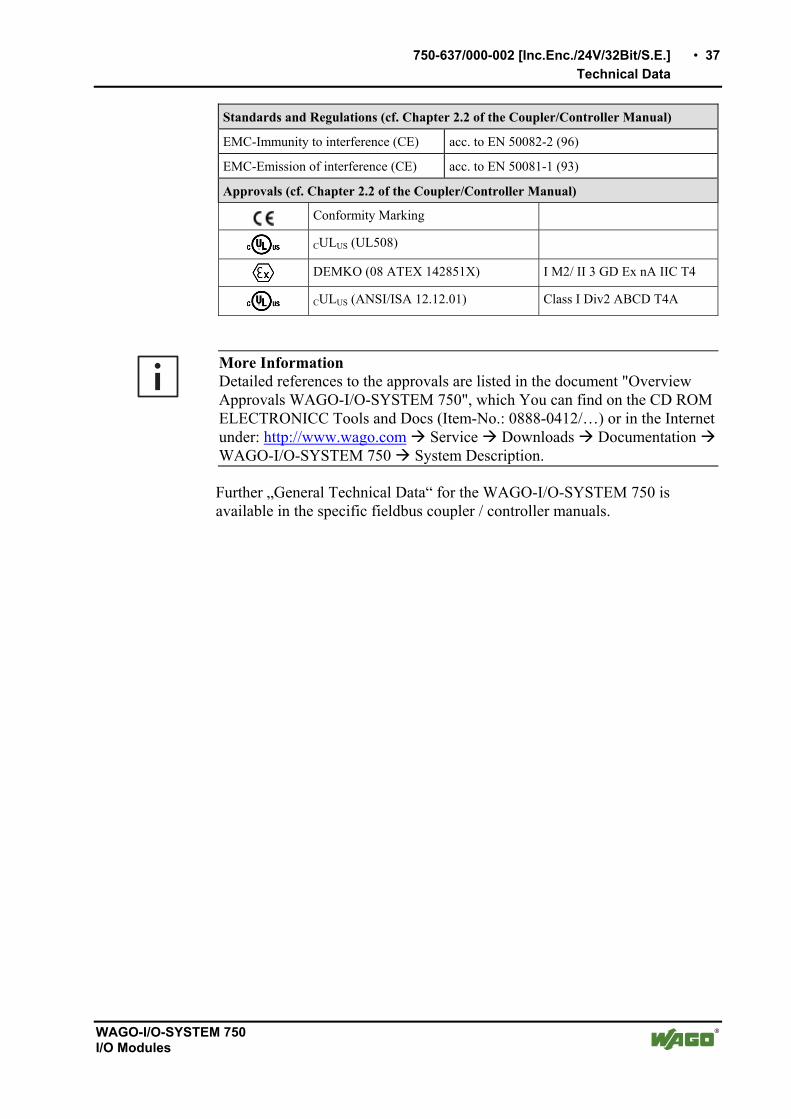
Standards and Regulations (cf. Chapter 2.2 of the Coupler/Controller Manual)
EMC-Immunity to interference (CE) acc. to EN 50082-2 (96)
EMC-Emission of interference (CE) acc. to EN 50081-1 (93)
Approvals (cf. Chapter 2.2 of the Coupler/Controller Manual)
Conformity Marking
CULUS (UL508)
DEMKO (08 ATEX 142851X) I M2/ II 3 GD Ex nA IIC T4
CULUS (ANSI/ISA 12.12.01) Class I Div2 ABCD T4A
More Information Detailed references to the approvals are listed in the document "Overview Approvals WAGO-I/O-SYSTEM 750", which You can find on the CD ROM ELECTRONICC Tools and Docs (Item-No.: 0888-0412/…) or in the Internet under: http://www.wago.com Service Downloads Documentation WAGO-I/O-SYSTEM 750 System Description.
Further „General Technical Data“ for the WAGO-I/O-SYSTEM 750 is available in the specific fieldbus coupler / controller manuals.

38 • 750-637/000-002 [Inc.Enc./24V/32Bit/S.E.]
Functional Description
WAGO-I/O-SYSTEM 750 I/O Modules
2.1.3.6 Functional Description
Typically, incremental encoders supply two output signals of the encoder track, both 90° offset. These signals are designated A and B. The difference of the input signals is evaluated in the incremental encoder I/O module.
Usually, incremental encoders have an index track in addition to the two track signals. This index track only produces one pulse per one full encoder revolu-tion. This pulse and the counter reading can be used to determine the absolute encoder position during rotation. The index pulse has a duration of a track po-sition pulse. We recommend to always have the latch process performed in the same rotational direction.
Input Function
A, B Quadrature input, 24 V, single ended Increment pulse signal channel A or B of the Incremental Encoder
C Zero reference input, 24 V, single ended Incremental encoder index pulse Dependent on the operating mode, the counter reading is taken over into the latch register or the counter showing the set value is additionally loaded, if the input edge is positive.
LATCH LATCH input 24 V Dependent on the operating mode, the counter reading is taken into the latch register or the counter showing the set value is additionally loaded, if the input edge is positive.
GATE GATE input, 24 V The counting process is locked if 24 V is applied to input GATE.
REF REF input, 24 V During a reference run, the index pulse is only evaluated in conjunction with an additional sensor signal (Ref).
Screen (Shield) Connection for the encoder line screen The screen connection is directly routed to the carrier rail.
+24V 24 V supply voltage for the module
0V Ground for the 24 V supply voltage
Output Function
N1, N2 Cam output, 24 V, 0.5 A "1" - Counter value is within of the defined range "0" - Counter value is outside of the defined range

750-637/000-002 [Inc.Enc./24V/32Bit/S.E.] • 39
Process Image
WAGO-I/O-SYSTEM 750 I/O Modules
2.1.3.7 Process Image
Using the I/O module 750-637/000-002, a 6 byte input and output process image can be transferred to the fieldbus coupler / controller via two logical channels.
The set values are stored in 4 output bytes (D0, D1, D2, D3) and the process data are stored in 4 input bytes (D0, D1, D2, D3). Two control bytes (C0, C1) and two status bytes (S0, S1) are used to select process data and set values as well as to control the data flow.
Attention The representation of the process data of some I/O modules or their variations in the process image depends on the fieldbus coupler/-controller used. Please take this information as well as the particular design of the respective control/status bytes from the section "Fieldbus Specific Design of the Process Data" included in the description concerning the process image of the corresponding coupler/controller.
Input data Output data
S0 Status byte S0 C0 Control byte C0
D0 Process data byte 0 (LSB) D0 Set value byte 0 (LSB)
D1 Process data byte 1 D1 Set value byte 1
S1 Status byte S1 C1 Control byte C1
D2 Process data byte 2 D2 Set value byte 2
D3 Process data byte 3 (MSB) D3 Set value byte 3 (MSB)
Bit 0 and bit 1 in the control byte C1 determines the process data.
Counter value Latch value Velocity
Set value
The setting is mirrored in status byte S1 in bit 0 and bit 1.
MapPZD (Control Byte C1 / Status Byte S1, Bit 0 and 1)
Bit 1 Bit 0 Coding of the Process data
0 0 Counter value
0 1 Latch value
1 0 Velocity (Increments per milliseconds)
1 1 Set value

40 • 750-637/000-002 [Inc.Enc./24V/32Bit/S.E.]
Process Image
WAGO-I/O-SYSTEM 750 I/O Modules
Status Byte S0
Bit 7 Bit 6 Bit 5 Bit 4 Bit 3 Bit 2 Bit 1 Bit 0
0 X AckSetLoadExt
OVER-FLOW
UNDER-FLOW
CNT_ SET_ ACK
LAT_ EXT_ VAL
LATC_VAL
LATC_ VAL
Acknowledge bit for EN_LATC (C0.0). Latch Mode: This bit is set with a positive edge at input C. It is reset when EN_LATC is reset. Preload Mode: This bit is set with a positive edge at C. It is reset when EN_LATC is reset.
LAT_ EXT_ VAL
Acknowledge bit for EN_LAT_EXT (C0.1). Latch Mode: This bit is set with a positive edge at the input Latch.
It is reset when EN_LAT_EXT is reset. Preload Mode: This bit is set with a positive edge at the input Latch.
It is reset when EN_LAT_EXT is reset.
CNT_ SET_ ACK
Acknowledge bit for CNT_SET (C0.2). Reset if CNT_SET=0
UNDER- FLOW
UNDERFLOW=1 with a counter overflow of 0x00000000 to 0xffffffff UNDERFLOW=0 if counter < 0xAAAAAAAA UNDERFLOW=0 if positive edge ResetUnderflow (C1.3) UNDERFLOW=0 if OVERFLOW=1
OVER- FLOW
OVERFLOW=1 with a counter overflow of 0xffffffff to 0x00000000 OVERFLOW=0 if counter > 0x55555555 OVERFLOW=0 if positive edge ResetOverflow (C1.4) OVERFLOW=0 if UNDERFLOW=1
AckSet LoadExt
Acknowledge bit for SetLoadExt.
Reset if SetLoadExt=0 (C0.5)
X reserved
0 reserved
Status Byte S1
Bit 7 Bit 6 Bit 5 Bit 4 Bit 3 Bit 2 Bit 1 Bit 0
0 0 N2 N1 StaN2 StaN1 MapPZD MapPZD
MapPZD Coding of process data (2 Bits)
StaN2 State of cam output 1: 0 = cam output 1 reset, 1 = cam output 1 set
StaN1 State of cam output 2: 0 = cam output 2 reset, 1 = cam output 2 set
N1 Cam window 1st bit is set, if:
bottom comparative value N1 <= Counter reading <= top comparative value N1
N2 Cam window 2nd bit is set, if:
bottom comparative value N2 <= Counter reading <= top comparative value N2
0 reserved

750-637/000-002 [Inc.Enc./24V/32Bit/S.E.] • 41
Process Image
WAGO-I/O-SYSTEM 750 I/O Modules
Control Byte C0
Bit 7 Bit 6 Bit 5 Bit 4 Bit 3 Bit 2 Bit 1 Bit 0
0 OpMode SetLoadExt
Reset Overflow
Reset Under-
flow
CNT_ SET
EN_ LAT_ EXT
EN_ LATC
EN_ LATC
The encoder zero mark is released.
Capture Mode: With a positive edge at input C the counter reading is transferred to the latch register.
Preload Mode: With a positive edge at input C the counter reading is transferred to the latch register . The counter is loaded with the set value.
The confirmation is de-selected for the negative edge of EN_LATC.
EN_LATC is dominant against EN_LAT_EXT.
EN_ LAT_ EXT
The external latch input is released.
Capture Mode: With a positive edge at the input LATCH, the counter reading is transferred to the latch register.
Preload Mode: With a positive edge at the input LATCH, the counter reading is transferred to the Latch register. The counter is loaded with the set value. The confirmation is de-selected for the negative edge of EN_LAT_EXT.
CNT_ SET With a positive edge, the counter is initialized on the set value.
Reset Underflow With a positive edge the status bit UNDERFLOW (S0.3) is reset.
Reset Overflow With a positive edge the status bit OVERFLOW (S0.4) is reset.
SetLoad Ext
With a positive edge, the set value to which the counter is to be set in the case of an external event, will be transferred to the process data.
OpMode 0=Capture Mode The counter is latched by a trigger signal
1=Preload Mode The counter is latched by a trigger signal.
Subsequently, the counter is loaded with the set value.
0 reserved

42 • 750-637/000-002 [Inc.Enc./24V/32Bit/S.E.]
Process Image
WAGO-I/O-SYSTEM 750 I/O Modules
Control Byte C1
Bit 7 Bit 6 Bit 5 Bit 4 Bit 3 Bit 2 Bit 1 Bit 0
0 Enable Ref
Set Nocke2
Set Nocke1
Dis Nocke2
Dis Nocke1
MapPZD MapPZD
MapPZD Coding of Process data (2 bits)
DisNocke1 Disable cam output 1: 0 = cam output 1 enabled, 1 = cam output 1 disabled
DisNocke2 Disable cam output 2: 0 = cam output 2 enabled, 1 = cam output 2 disabled
SetNocke1 With a positive edge, the set value is taken over as the bottom comparative value for output 1 (N1).
With a negative edge, the set value is taken over as the top comparative value for output 1 (N1).
SetNocke2 With a positive edge, the set value is taken over as bottom comparative value for output 2 (N2).
With a negative edge, the set value is taken over as top comparative value for output 2 (N2).
EnableRef Input REF released.
- The controls set Bit EnableRef
- The controls must release EN_LATC (C1.0) or EN_LAT_EXT (C1.1) with a positive edge
- A positive edge is created at input REF
- Subsequently, the next positive edge at input C or input Latch leads to a Capture or Preload event
0 reserved

750-637/000-004 [Inc.Enc./24V/32Bit/S.E./cam] • 43
View
WAGO-I/O-SYSTEM 750 I/O Modules
2.1.4 750-637/000-004 [Inc.Enc./24V/32Bit/S.E./cam]
Incremental encoder interface 24 V / 32 bit / single ended / cam outputs
2.1.4.1 View
+ -
L G
R S
15 16
C
D
B
A
C
13 14
C
D
B
A
750-637/000-004
B
A
N1 N2
C
AB
Latch
A
B
C GateLatch
N 2N 1
0V24V
N 1N 2GateRef
Ref
Data contacts
Shield (screen)
Fig. 2.1.4-1: View g063740e
2.1.4.2 Description
The I/O module 750-637/000-004 represents an interface for any type of incremental encoder with an single ended 24 V connection.
The data width of the encoder module is 32 bits. Either the current counter reading, the latch value, the set value or the current speed can be mapped into the process data.
Inputs/Outputs
A, B Quadrature input, 24 V, single ended
C Zero reference input, 24 V, single ended
Latch, Gate, Ref Input, 24 V
N1, N2 Output, 24 V
A counter with quadrature decoder and a latch for the zero pulse can be read and activated by the PLC. The PLC is able to set the counter. Depending on the operating mode, the counter reading is taken into the latch register, if the edge at input “C” or “Latch” is positive.
The speed (increments/ms) is automatically recorded and can be transmitted as an alternative to the latch value.

44 • 1BI/O Modules
750-637/000-004 [Inc.Enc./24V/32Bit/S.E./cam]
WAGO-I/O-SYSTEM 750 I/O Modules
The „Gate” input allows to lock the counter. The „Ref” input can be set to activate the zero mark „C”.
The I/O module signals whether the counter reading is within the defined set points by using the cam outputs (N1, N2). The set points can be individually set.
The I/O module requires 24 VDC power supply. The sensor is fed with an external power supply. The sensor ground must be connected to the 0V terminal of the module.
Attention This module has no power contacts. For field supply to downstream I/O modules, a supply module will be needed.
The shield (screen) is directly connected to the carrier rail.
The module 750-637/000-002 can be used with all couplers/controllers of the WAGO-I/O-SYSTEM 750 (except for the economy types 750-320, -323, -324 and -327).
This description is valid for the XXXX0101... hardware and software version. The version is specified in the manufacturing number, which is part of the lateral marking on the module.

750-637/000-004 [Inc.Enc./24V/32Bit/S.E./cam] • 45
Display Elements
WAGO-I/O-SYSTEM 750 I/O Modules
2.1.4.3 Display Elements
LED Designation Status Function
off 0 V < U(A) < 5 V or input open A1 A
green 30 V > U(A) > 15 V
off 0 V < U(C) < 5 V or input open B1 C
green 30 V > U(C) > 15 V
off 0 V < U(B) < 5 V or input open C1 B
green 30 V > U(B) > 15 V
off Input = 0 V or open D1 Latch
green Input = 24 V
off Input = 0 V or open A2 Gate
green Input = 24 V
off Output = 0 V B2 N1
green Output = 24 V
off Input = 0 V or open C2 Ref
green Input = 24 V
off Output = 0 V
15 16
C
D
B
A
13 14
C
D
B
A
B1
A1C1
D1
B2
A2C2
D2
Fig. 2.1.4-2: Display elements g063702x
D2 N2 green Output = 24 V
2.1.4.4 Schematic Diagram
24V/0V A B C
N1/N2
N1/N2
Latch/Gate
N1/N2
Gate/Ref
DC
DC
Logic
A
B
C
Ref/Shield(screen)
Latch
Gate/Ref
A,B,C
0V
24V
Latch
Shield(screen)
1
2
3
4
5
6
7
8
750-637/000-004
1
2
3
4
5
6
7
8
Fig. 2.1.4-2: Schematic Diagram g063741e

46 • 1BI/O Modules
750-637/000-004 [Inc.Enc./24V/32Bit/S.E./cam]
WAGO-I/O-SYSTEM 750 I/O Modules
2.1.4.5 Technical Data
Module specific Data
Sensor connection A, B, C, 0 V
Current consumption (internal) 110 mA
Counter 32 bits binary
Operation Mode Capture 32 bits
Operation Mode Preload 32 bits
Quadrature decoder 4-fold report
Zero impulse latch 32 bits
Commands read, write, activate
Velocity 16 Bit (Increments per 1ms)
Max. operating frequency 250 kHz
Time constant input LATCH 364 µs
Time constant input GATE 32 µs
Time constant input REF 32 µs
Power supply DC 24 V (- 15 % ... + 20 %)
Undervoltage diagnostics (0) DC 28,8 V > supply voltage > DC 20,4 V (1) DC 0 V < supply voltage < DC 5 V
Current consumption (24 V) 12 mA (without sensor and without load)
Sensor Operation voltage DC 5 V
Sensor Output current max 300 mA
Internal bit width 1 x 32 bits data 2 x 8 bits control/status
Dimensions W x H* x L * from upper edge of DIN 35 rail
24 mm x 64 mm x 100 mm
Weight ca. 105 g
Digital Outputs (N1, N2)
Output voltage DC 24 V
Output current max. 0,5 A short-circuit-protected
Output resistancetyp. 160 m
Digital Inputs (Latch, Gate, Ref)
Input voltage (0) DC –3 V ... +5 V (1) DC +15 V ... +30 V
Input current typ. Latch: 5 mA Gate and Ref: 7 mA

750-637/000-004 [Inc.Enc./24V/32Bit/S.E./cam] • 47
Functional Description
WAGO-I/O-SYSTEM 750 I/O Modules
Quadrature Inputs (A, /A, B, /B, C, /C)
Input voltage A, /A (0) DC 0 V < U(A) < DC 5 V (1) DC 30 V > U(A) > DC 15 V
Input voltage B, /B (0) DC 0 V < U(B) < DC 5 V (1) DC 30 V > U(B) > DC 15 V
Input voltage C, /C (0) DC 0 V < U(C) < DC 5 V (1) DC 30 V > U(B) > DC 15 V
Standards and Regulations (cf. Chapter 2.2 of the Coupler/Controller Manual)
EMC-Immunity to interference (CE) acc. to EN 50082-2 (96)
EMC-Emission of interference (CE) acc. to EN 50081-1 (93)
Approvals (cf. Chapter 2.2 of the Coupler/Controller Manual)
Conformity Marking
CULUS (UL508)
DEMKO (08 ATEX 142851X) I M2/ II 3 GD Ex nA IIC T4
CULUS (ANSI/ISA 12.12.01) Class I Div2 ABCD T4
More Information Detailed references to the approvals are listed in the document "Overview Approvals WAGO-I/O-SYSTEM 750", which You can find on the CD ROM ELECTRONICC Tools and Docs (Item-No.: 0888-0412/…) or in the Internet under: http://www.wago.com Service Downloads Documentation WAGO-I/O-SYSTEM 750 System Description.
Further „General Technical Data“ for the WAGO-I/O-SYSTEM 750 is available in the specific fieldbus coupler / controller manuals.
2.1.4.6 Functional Description
Typically, incremental encoders supply two output signals of the encoder track, both 90° offset. These signals are designated A and B. The difference of the input signals is evaluated in the incremental encoder I/O module.
Usually, incremental encoders have an index track in addition to the two track signals. This index track only produces one pulse per one full encoder revolu-tion. This pulse and the counter reading can be used to determine the absolute encoder position during rotation. The index pulse has a duration of a track po-sition pulse. We recommend to always have the latch process performed in the same rotational direction.

48 • 1BI/O Modules
750-637/000-004 [Inc.Enc./24V/32Bit/S.E./cam]
WAGO-I/O-SYSTEM 750 I/O Modules
Input Function
A, B Quadrature input, 24 V, single ended Increment pulse signal channel A or B of the Incremental Encoder
C Zero reference input, 24 V, single ended Incremental encoder index pulse Dependent on the operating mode, the counter reading is taken over into the latch register or the counter showing the set value is additionally loaded, if the input edge is positive.
LATCH LATCH input 24 V Dependent on the operating mode, the counter reading is taken into the latch register or the counter showing the set value is additionally loaded, if the input edge is positive.
GATE GATE input, 24 V The counting process is locked if 24 V is applied to input GATE.
REF REF input, 24 V During a reference run, the index pulse is only evaluated in conjunction with an additional sensor signal (Ref).
Screen (Shield) Connection for the encoder line screen The screen connection is directly routed to the carrier rail.
+24V 24 V supply voltage for the module
0V Ground for the 24 V supply voltage
Output Function
N1, N2 Cam output, 24 V, 0.5 A "1" - Counter value is whithin window 1 or window 2 "0" - Counter value is outside window 1 or window 2 The cams can be globally enabled or locked. This guarantees that no unexpected switching states occur due to changes of the windows in operating mode. All cam outputs are reset (output voltage 0 V) in the event of a field voltage failure. When the voltage is restored, all cams remain reset independent of the previous switching state (output voltage 0 V). The voltage failure is reported to the control unit via a status bit. The cam windows must then be set anew.

750-637/000-004 [Inc.Enc./24V/32Bit/S.E./cam] • 49
Process Image
WAGO-I/O-SYSTEM 750 I/O Modules
2.1.4.7 Process Image
Using the I/O module 750-637/000-004, a 6 byte input and output process image can be transferred to the fieldbus coupler / controller via two logical channels.
The set values are stored in 4 output bytes (D0, D1, D2, D3) and the process data are stored in 4 input bytes (D0, D1, D2, D3). Two control bytes (C0, C1) and two status bytes (S0, S1) are used to select process data and set values as well as to control the data flow.
Attention The representation of the process data of some I/O modules or their variations in the process image depends on the fieldbus coupler/-controller used. Please take this information as well as the particular design of the respective control/status bytes from the section "Fieldbus Specific Design of the Process Data" included in the description concerning the process image of the corresponding coupler/controller.
Input data Output data
S0 Status byte S0 C0 Control byte C0
D0 Process data byte 0 (LSB) D0 Set value byte 0 (LSB)
D1 Process data byte 1 D1 Set value byte 1
S1 Status byte S1 C1 Control byte C1
D2 Process data byte 2 D2 Set value byte 2
D3 Process data byte 3 (MSB) D3 Set value byte 3 (MSB)
Bit 0 and bit 1 in the control byte C1 determines the process data.
Counter value Latch value
The setting is mirrored in status byte S1 in bit 0 and bit 1.
MapPZD (Control Byte C1 / Status Byte S1, Bit 0)
Bit 0 Coding of the Process data
0 Counter value
0 Latch value

50 • 1BI/O Modules
750-637/000-004 [Inc.Enc./24V/32Bit/S.E./cam]
WAGO-I/O-SYSTEM 750 I/O Modules
Status Byte S0
Bit 7 Bit 6 Bit 5 Bit 4 Bit 3 Bit 2 Bit 1 Bit 0
0 PF AckSetLoadExt
OUF Enable_Nocken_
Ack
CNT_ SET_ ACK
LAT_ EXT_ VAL
LATC_VAL
LATC_ VAL
Acknowledge bit for EN_LATC (C0.0). Latch Mode: This bit is set with a positive edge at input C. It is reset when EN_LATC is reset. Preload Mode: This bit is set with a positive edge at C. It is reset when EN_LATC is reset.
LAT_ EXT_ VAL
Acknowledge bit for EN_LAT_EXT (C0.1). Latch Mode: This bit is set with a positive edge at the input Latch. It is reset when EN_LAT_EXT is reset. Preload Mode: This bit is set with a positive edge at the input Latch. It is reset when EN_LAT_EXT is reset.
CNT_ SET_ ACK
Acknowledge bit for CNT_SET (C0.2). Reset if CNT_SET=0
Enable_ Nocken_ Ack
Acknowledgement bit for Enable_Cams ( C1.6 ) When the acknowledgement bit and the request bit are identical, the command was executed by the module. The cam outputs have the desired state.
OUF Combined over/underflow status bit Set/reset conditions:
Underflow function (rotational direction "left") Bit = 1 for counter having passed the underflow value from 0x00000000 to 0xffffffff Bit = 0 if then the counter reading is < 0xAAAAAAAA Bit = 0 for acknowledgement, therefore with a positive edge RESET_OUF (C0.4) Bit = 0 at overflow event without previous acknowledgement
Overflow function (rotational direction "right") Bit = 1 for counter having passed the overflow value from 0xffffffff to 0x00000000 Bit = 0 if then the counter reading is > 0x55555555 Bit = 0 for acknowledgement, therefore with a positive edge RESET_OUF (C0.4) Bit = 0 if overflow event without previous acknowledgement
AckSet LoadExt
Acknowledge bit for SetLoadExt.
Reset if SetLoadExt=0 (C0.5)
PF The loss of field power is indicated. ( Powerfail ) Bit = 1 The field voltage is < 5 V Bit = 0 The field voltage is > 20.4 V After a power failure, all cam windows are set to 0. The counter reading is set to 0.
0 reserved

750-637/000-004 [Inc.Enc./24V/32Bit/S.E./cam] • 51
Process Image
WAGO-I/O-SYSTEM 750 I/O Modules
Status Byte S1
Bit 7 Bit 6 Bit 5 Bit 4 Bit 3 Bit 2 Bit 1 Bit 0
0 0 N2_F1 N1_F1 N2_F2 N1_F2 Set Nocken_
Ack
MapPZD
MapPZD Coding of process data The request bit ( C1.0 ) to show the counter or latch value is acknowledged. The requested value in the input data process is valid.
Set Nocken_ Ack
Collective acknowledgement bit for all cam set requests. The bit is set if one or several of the request bits 2, 3, 4 or 5 are set by control byte C1.
N1_F2 Cam 1, window 2 The bit is set if bottom comparison value N1F2_LO < counter reading < upper comparison value N1F2_HI and the cams are enabled ( C1.6 ), and the field voltage is available ( S0.6 = 0).
N2_F2 Cam 2, window 2 The bit is set if bottom comparison value N2F2_LO < counter reading < upper comparison value N2F2_HI and the cams are enabled ( C1.6 ), and the field voltage is available ( S0.6 = 0).
N1_F1 Cam 1, window 1 The bit is set if bottom comparison value N1F1_LO < counter reading < upper comparison value N1F1_HI and the cams are enabled ( C1.6 ), and the field voltage is available ( S0.6 = 0).
N2_F1 Cam 2, window 1 The bit is set if bottom comparison value N2F1_LO < counter reading < upper comparison value N2F1_HI and the cams are enabled ( C1.6 ), and the field voltage is available ( S0.6 = 0).
0 Reserved (These bits should be masked in the PLC)

52 • 1BI/O Modules
750-637/000-004 [Inc.Enc./24V/32Bit/S.E./cam]
WAGO-I/O-SYSTEM 750 I/O Modules
Control Byte C0
Bit 7 Bit 6 Bit 5 Bit 4 Bit 3 Bit 2 Bit 1 Bit 0
0 OpMode SetLoadExt
Reset Overflow
Reset Under-
flow
CNT_ SET
EN_ LAT_ EXT
EN_ LATC
EN_ LATC
The encoder zero mark is released.
Capture Mode: With a positive edge at input C the counter reading is transferred to the latch register.
Preload Mode: With a positive edge at input C the counter reading is transferred to the latch register . The counter is loaded with the set value.
The confirmation is de-selected for the negative edge of EN_LATC.
EN_LATC is dominant against EN_LAT_EXT.
EN_ LAT_ EXT
The external latch input is released.
Capture Mode: With a positive edge at the input LATCH, the counter reading is transferred to the latch register.
Preload Mode: With a positive edge at the input LATCH, the counter reading is transferred to the Latch register. The counter is loaded with the set value. The confirmation is de-selected for the negative edge of EN_LAT_EXT.
CNT_ SET With a positive edge, the counter is initialized on the set value.
Reset Underflow With a positive edge the status bit UNDERFLOW (S0.3) is reset.
Reset Overflow With a positive edge the status bit OVERFLOW (S0.4) is reset.
SetLoad Ext
With a positive edge, the set value to which the counter is to be set in the case of an external event, will be transferred to the process data.
OpMode Bit = 0 Capture Mode The counter is latched by a trigger signal
Bit = 1 Preload Mode The counter is latched by a trigger signal. Subsequently, the counter is loaded with the set value.
0 reserved

750-637/000-004 [Inc.Enc./24V/32Bit/S.E./cam] • 53
Process Image
WAGO-I/O-SYSTEM 750 I/O Modules
Control Byte C1
Bit 7 Bit 6 Bit 5 Bit 4 Bit 3 Bit 2 Bit 1 Bit 0
0 Enable_Nocken
Set Nocke2_
F1
Set Nocke1_
F1
Set Nocke2_
F2
Set Nocke1_
F2
INV_ GATE
MapPZD
MapPZD Coding of process data Bit = 0 Counter value Bit = 1 Latch value
INV _GATE
Bit = 0 The counting process is disabled when 24V is applied to the GATE input. Bit = 1 The counting process is disabled when 0V is applied to the GATE input or when the input is open. Notice: The request is not acknowledged in the status byte!
SetNocke1 _F2
With a positive edge, the set value is taken over as bottom comparison value N1F2_LO for cam output 1 (N1) window F2. With a negative edge, the set value is taken over as upper comparison value N1F2_HI for cam ouput 1 (N1) window F2.
SetNocke2 _F2
With a positive edge, the set value is taken over as bottom comparison value N2F2_LO for cam output 2 (N2) window F2. With a negative edge, the set value is taken over as upper comparison value N2F2_HI for cam ouput 2 (N2) window F2.
SetNocke1 _F1
With a positive edge, the set value is taken over as bottom comparison value N1F1_LO for cam output 1 (N1) window F1. With a negative edge, the set value is taken over as upper comparison value N1F1_HI for cam ouput 1 (N1) window F1.
SetNocke2 _F1
With a positive edge, the set value is taken over as bottom comparison value N2F1_LO for cam output 2 (N2) window F1. With a negative edge, the set value is taken over as upper comparison value N2F1_HI for cam ouput 2 (N2) window F1.
Enable _Nocken
Bit = 0 All cam outputs are disabled; i.e., output voltage 0 V Bit = 1 All cam outputs are enabled; i.e., output voltage 24 V The request is acknowledged in status bit Enable_Cams (S0.3).
0 reserved

54 • Use in Hazardous Environments
10BSpecial Modules
WAGO-I/O-SYSTEM 750 I/O Modules
Use in Hazardous Environments
The WAGO-I/O-SYSTEM 750 (electrical equipment) is designed for use in Zone 2 hazardous areas.
The following sections include both the general identification of components (devices) and the installation regulations to be observed. The individual subsections of the "Installation Regulations" section must be taken into account if the I/O module has the required approval or is subject to the range of application of the ATEX directive.

Use in Hazardous Environments • 55
Identification
WAGO-I/O-SYSTEM 750 I/O Modules
2.2 Identification
2.2.1 For Europe according to CENELEC and IEC
Fig. 2.2.1-1: Example for lateral labeling of bus modules (750-400, 2 channel digital input module 24 V DC) p01xx03x
Fig. 2.2.1-2: Printing on text detail in accordance with CENELEC and IEC p01xx04x
Tab. 0-1: Description of Printing on
Printing on Text Description
DEMKO 08 ATEX 142851 XIECEx PTB 07.0064X
Approval body and/or number of the examination certificate
I M2 / II 3 GD Device group and Unit category
Ex nA Type of ignition and extended identification
IIC Device group
T4 Temperature class

56 • Use in Hazardous Environments
Identification
WAGO-I/O-SYSTEM 750 I/O Modules
Figure 1: Example of side marking of Ex i and IEC Ex i approved I/O modules
Figure 2: Inscription text detail acc. CENELEC and IEC

Use in Hazardous Environments • 57
Identification
WAGO-I/O-SYSTEM 750 I/O Modules
Table 1: Description of the inscription
Inscription text Description TÜV 07 ATEX 554086 X TUN 09.0001X
Approving authority or certificate numbers
Dust II Device group: All except mining 3(1)D Device category: Zone 22 device (Zone 20 subunit) Ex Explosion protection mark tD Protection by enclosure [iaD] Approved in accordance with "Dust intrinsic safety"
standard A22 Surface temperature determined according to
Procedure A, use in Zone 22 IP6X Dust-tight (totally protected against dust) T 135°C Max. surface temp. of the enclosure (no dust bin) Mining I Device group: Mining (M2) Device category: High degree of safety [Ex ia] Explosion protection: Mark with category of type of
protection intrinsic safety: Even safe when two errors occur
I Device group: Mining Gases II Device group: All except mining 3(1)G Device category: Zone 2 device (Zone 0 subunit) Ex Explosion protection mark nA Type of protection: Non-sparking operating
equipment [ia] Category of type of protection intrinsic safety: Even
safe when two errors occur IIC Explosion Group T4 Temperature class: Max. surface temperature 135°C

58 • Use in Hazardous Environments
Identification
WAGO-I/O-SYSTEM 750 I/O Modules
2.2.2 For America according to NEC 500
Fig. 2.2.2-3: Example for lateral labeling of bus modules (750-400, 2 channel digital input
module 24 V DC) p01xx03x
Fig. 2.2.2-4: Printing on text detail in accordance with CENELEC and IEC p01xx05x
Tab. 0-2: Description of Printing on
Printing on Text Description
CL 1 Explosion protection group (condition of use category)
DIV 2 Area of application (zone)
Grp. ABCD Explosion group (gas group)
Op temp. code T4 Temperature class

Use in Hazardous Environments • 59
Installation Regulations
WAGO-I/O-SYSTEM 750 I/O Modules
2.3 Installation Regulations
In the Federal Republic of Germany, various national regulations for the installation in explosive areas must be taken into consideration. The basis for this forms the working reliability regulation, which is the national conversion of the European guideline 99/92/E6. They complemented by the installation regulation EN 60079-14. The following are excerpts from additional VDE regulations:
Tab. 0-3: VDE Installation Regulations in Germany
Standard Installation Regulations
DIN VDE 0100 Installation in power plants with rated voltages up to 1000 V
DIN VDE 0101 Installation in power plants with rated voltages above 1 kV
DIN VDE 0800 Installation and operation in telecommunication plants including information processing equipment
DIN VDE 0185 lightning protection systems
The USA and Canada have their own regulations. The following are excerpts from these regulations:
Tab. 0-4: Installation Regulations in USA and Canada
Standard Installation Regulations
NFPA 70 National Electrical Code Art. 500 Hazardous Locations
ANSI/ISA-RP 12.6-1987 Recommended Practice
C22.1 Canadian Electrical Code
Warning When using the WAGO-I/O SYSTEM 750 (electrical operation) with Ex approval, the following points are mandatory:

60 • Use in Hazardous Environments
Installation Regulations
WAGO-I/O-SYSTEM 750 I/O Modules
2.3.1 Special Conditions for Safe Operation of the ATEX and IEC Ex (acc. DEMKO 08 ATEX 142851X and IECEx PTB 07.0064)
The fieldbus-independent I/O modules of the WAGO-I/O-SYSTEMs 750-.../...-... Must be installed in an environment with degree of pollution 2 or better. In the final application, the I/O modules must be mounted in an enclosure with IP 54 degree of protection at a minimum with the following exceptions:
- I/O modules 750-440, 750-609 and 750-611 must be installed in an IP 64 minimum enclosure.
- I/O module 750-540 must be installed in an IP 64 minimum enclosure for 230 V AC applications.
- I/O module 750-440 may be used up to max. 120 V AC.
When used in the presence of combustible dust, all devices and the enclosure shall be fully tested and assessed in compliance with the requirements of IEC 61241-0:2004 and IEC 61241-1:2004.
I/O modules fieldbus plugs or fuses may only be installed, added, removed or replaced when the system and field supply is switched off or the area exhibits no explosive atmosphere.
DIP switches, coding switches and potentiometers that are connected to the I/O module may only be operated if an explosive atmosphere can be ruled out.
I/O module 750-642 may only be used in conjunction with antenna 758-910 with a max. cable length of 2.5 m.
To exceed the rated voltage no more than 40%, the supply connections must have transient protection.
The permissible ambient temperature range is 0 °C to +55 °C.

Use in Hazardous Environments • 61
Installation Regulations
WAGO-I/O-SYSTEM 750 I/O Modules
2.3.2 Special conditions for safe use (ATEX Certificate TÜV 07 ATEX 554086 X)
1. For use as Gc- or Dc-apparatus (in zone 2 or 22) the fieldbus independent I/O modules WAGO-I/O-SYSTEM 750-*** shall be erected in an enclosure that fulfils the requirements of the applicable standards (see the marking) EN 60079-0, EN 60079-11, EN 60079-15, EN 61241-0 and EN 61241-1. For use as group I, electrical apparatus M2, the apparatus shall be erected in an enclosure that ensures a sufficient protection according to EN 60079-0 and EN 60079-1 and the degree of protection IP64. The compliance of these requirements and the correct installation into an enclosure or a control cabinet of the devices shall be certified by an ExNB.
2. If the interface circuits are operated without the fieldbus coupler station type 750-3../…-… (DEMKO 08 ATEX 142851 X) measures must be taken outside of the device so that the rating voltage is not being exceeded of more than 40% because of transient disturbances.
3. DIP-switches, binary-switches and potentiometers, connected to the module may only be actuated when explosive atmosphere can be excluded.
4. The connecting and disconnecting of the non-intrinsically safe circuits is only permitted during installation, for maintenance or for repair purposes. The temporal coincidence of explosion hazardous atmosphere and installation, maintenance resp. repair purposes shall be excluded.
5. For types 750-606, 750-625/000-001, 750-487/003-000, 750-484, the following must be taken into account: The interface circuits must be limited to overvoltage category I/II/III (electrical circuits without power supply/electrical circuits with power supply) as defined in EN 60664-1.
6. For the type 750-601 the following shall be considered: Do not remove or replace the fuse when the apparatus is energized.
7. The ambient temperature range is: 0°C ≤ Ta ≤ +55°C (for extended details please note certificate).

62 • Use in Hazardous Environments
Installation Regulations
WAGO-I/O-SYSTEM 750 I/O Modules
2.3.3 Special conditions for safe use (IEC-Ex Certificate TUN 09.0001 X)
1. For use as Dc- or Gc-apparatus (in zone 2 or 22) the fieldbus independent I/O modules WAGO-I/O-SYSTEM 750-*** shall be erected in an enclosure that fulfils the requirements of the applicable standards (see the marking) IEC 60079-0, IEC 60079-11, IEC 60079-15, IEC 61241-0 and IEC 61241-1. For use as group I, electrical apparatus M2, the apparatus shall be erected in an enclosure that ensures a sufficient protection according to IEC 60079-0 and IEC 60079-1 and the degree of protection IP64. The compliance of these requirements and the correct installation into an enclosure or a control cabinet of the devices shall be certified by an ExCB.
2. Measures have to be taken outside of the device that the rating voltage is not being exceeded of more than 40% because of transient disturbances.
3. DIP-switches, binary-switches and potentiometers, connected to the modulemay only be actuated when explosive atmosphere can be excluded
4. The connecting and disconnecting of the non-intrinsically safe circuits is only permitted during installation, for maintenance or for repair purposes. The temporal coincidence of explosion hazardous atmosphere and installation, maintenance resp. repair purposes shall be excluded.
5. For the types 750-606, 750-625/000-001, 750-487/003-000, 750-484 the following shall be considered: The interface circuits shall be limited to overvoltage category I/II/III (non mains/mains circuits) as defined in IEC 60664-1.
6. For the type 750-601 the following shall be considered: Do not remove or replace the fuse when the apparatus is energized.
7. The ambient temperature range is: 0°C ≤ Ta ≤ +55°C (for extended details please note certificate).

Use in Hazardous Environments • 63
Installation Regulations
WAGO-I/O-SYSTEM 750 I/O Modules
2.3.4 ANSI/ISA 12.12.01
This equipment is suitable for use in Class I, Division 2, Groups A, B, C, D or non-hazardous locations only.
Warning Explosion hazard - substitution of components may impair suitability for Class I, Div. 2.
Warning Do not disconnect equipment unless power has been switched off or the area is known to be non-hazardous.
When a fuse is provided, the following marking shall be provided: ”A switch suitable for the location where the equipment is installed shall be provided to remove the power from the fuse.” The switch need not be integrated in the equipment.
For devices with Ethernet connectors: ”Only for use in LAN, not for connection to telecommunication circuits.”
Warning Use Module 750-642 only with antenna module 758-910.

WAGO Kontakttechnik GmbH & Co. KG Postfach 2880 • D-32385 Minden Hansastraße 27 • D-32423 Minden Phone: 05 71/8 87 – 0 Fax: 05 71/8 87 – 1 69 E-Mail: [email protected] Internet: http://www.wago.com