

Field Testing of fiber optic - BICSI · Field Testing of fiber optic ... • The averaging can be...
35
Field Testing of fiber optic Field Testing of fiber optic infrastructure for 10, 40 and 100Gbits/s readiness Christian Schillab Product Manager Media Test Fluke Networks Europe Member British Standards Institute Working Group TCT 7/ /1 Member British Standards Institute Working Group TCT 7/‐/1 & CENELEC TC215 WG1 PTH und PTT [email protected]
Transcript of Field Testing of fiber optic - BICSI · Field Testing of fiber optic ... • The averaging can be...

Field Testing of fiber opticField Testing of fiber optic infrastructure for
10, 40 and 100Gbits/s readinessChristian Schillab
Product Manager Media TestFluke Networks Europe
Member British Standards Institute Working Group TCT 7/ /1Member British Standards Institute Working Group TCT 7/‐/1 & CENELEC TC215 WG1 PTH und PTT

Topics
• Intelligent test regimes which optimize performance margins g g p p gwith little increase in testing time
• The evaluation & documentation of the performance and diti f th t t tcondition of the test set up
• Choosing the optimal test method for complex hybrid channels
• Testing of complex and demanding MPO‐cassettes based channels with a later migration to 40GBASE‐R4, 100GBSE‐SR10 i i dSR10 in mind

• With 40GBASE‐R4, 100GBSE‐SR10 a trend ,continues which provides significantly higher bandwidth at the expense of distance and pinsertion loss budget ?
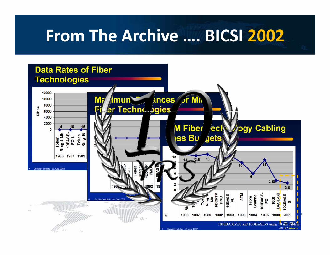
From The Archive …. BICSI 2002

IEEE 802.3ba – 40/100GB/s
Justification for Field Testing / Inspection1 Field ermination1. Field ermination
2. Patched multi segment channels– Multi vendor– Multi vendor
– Add Changes and Moves performed by operator
3 Dust effects performance3. Dust effects performance
4. Demanding limits

IEEE 802.3ba – Field Testing ?Wie wichtig ist die Abnahmemessung ?
Structured Cabling/
Structured Cabling/ Connector Less“ ChannelConnector Less“ Channel
g
Permanent Link / ChannelPermanent Link / Channel „Connector Less Channel„Connector Less Channel

40/100 GbE Fiber Applicationspp
40GBASE‐SR4 40GBASE‐LR4 40GBASE‐FR
Mulitmode Single Mode
Source 4 x 10Gb VCSEL 4 x 10Gb Laser 1 x 40Gb L100GBASE‐SR10 100GBASE‐LR4 100GBASE‐ER4Laser
Optics Parallel Simplex
Connnector MPO LC (or similar)
100GBASE‐SR10 100GBASE‐LR4 100GBASE‐ER4
Mulitmode Single Mode
Source 10 x 10Gb VCSEL 4 x 10Gb Laser 1 x 40Gb LaserWavelenght 850 nm 1271‐1331 nm 1550
Fiber OM3 OM4 OS2 OS2
Max Distance 100 m 150 m 10 000 m 2 000m
Optics Parallel Simplex (4λ@ 25Gb)
Connnector MPO LC (or similar)
W l ht 850 1300 1550Max Distance 100 m 150 m 10,000 m 2,000m
Loss Budget 1,9 dB 1,53 dB 6.7 dB 4.0 dBWavelenght 850 nm 1300 nm
(DWDM)1550 nm (DWDM)
Fiber OM3 OM4 OS2 OS2
Max Distance 100 m 150 m 10,000 m 40,000m
Loss Budget 1,9 dB 1,53 dB 8.3 dB 18 dB

40/100GBase40/100GBase‐‐SR/LR/ER: SR/LR/ER: Which ISO Channel supports it ?Which ISO Channel supports it ?

Fiber Optic Test Methodes
Standard Methods
TIA 568 C
p
TIA‐568‐C
Tier‐1 Tier‐2
ISO 11801 AMD.1 / ISO/IEC 1476‐3
BASIC Test Regime EXTENDED Test Regime
LSPM: Light Source & Power Meter OTDR: Optical Time Domain Reflectometer
• The two methods are complimentary !– OTDR based method does not replace the LSPM based solution
• Both methods have advantages and limitations

OTDR’s Have Multiple “Points of View”
- 0.23 dB + 0.41 dB
0.33 dB 0.32 dB
+ 0.44 dB - 0.20 dB

Causes for “Directivity”
Potential causes for different results depending h di ion the direction
1. Two fibers are different– Diameter
– Back Scatter Index
– NA …. Numerical Aperture
– Major difference in IR … Index of Refractionj
2. Damaged fiber end faces– Glass is chipped offGlass is chipped off

Bi Directional Averaging
• The averaging can be performed manually or by advanced results management softwareg

Can We Quantify “Directivity”• No standard defines how to calculate it
… but it is simple
• ISO/IEC 14763‐3 defines no maximum allowed “directivity”• ISO/IEC 14763‐3 defines no maximum allowed directivity

How to Quantify Directivity
• Delta of measured loss from End‐1 and End‐2 divided by two
@ 0m: Δ ( 0 23 and 0 41) / 2 = 0 6 / 2 = 0 3dB@ 0m: Δ (‐0.23 and 0.41) / 2 = 0.6 / 2 = 0.3dB
@50m: Δ (0.44 and ‐ 0.20) / 2 = 0.6 / 2 = 0.3dB
• In this example: Prior to averaging the result will be over stated byIn this example: Prior to averaging the result will be over stated by 0.30dB in one and understated by 0.3dB in the other directions
• NOTE: The overall loss is not suffering from directivity– Only if launch and receive fiber exhibit no directivity
if tested without a link

No Bi‐Directional Averaging ‐ Consequences
• A directivity of 0.2 – 0.4 can often be seen with out mixing 50 and 60µm and new and OM1/2 fiber
• Even fiber from the same supplier will show up to 0.15dB of directivity
• For this example we assume a 100m patch panel to patch panel link with connectors win an IL ranging from 0.15 to 0.25dB. The fibers loss is 3dB/km
• The assumed directivity is 0.2dB for launch/tail fiber ↔ link and ~ 0dB
Actual LimitMeas.f End‐1
Meas.f End‐2
Avg.Meas
y /between launch & tail
Actual LimitMeas. Meas. Avg.f. End 1 f. End 2 Meas.
0 m 0.15 dB 0.75 dB ‐0.05 0.35 0.15
100m 0.25 dB 0.75 dB 0.45 0.05 0.25
Actual Limitf. End‐1 f. End‐2 Meas.
0 m 0.15 dB 0.30 dB ‐0.05 0.35 0.15
100m 0.25 dB 0.30 dB 0.45 0.05 0.25 Atten.Koeff. 3dB/km 3.5dB/km 3.00 3.00 3.00
Overall Loss 0.70 dB 1.85 dB 0.70 0.70 0.70 Atten.Koeff. 3dB/km 3.5dB/km 3.00 3.00 3.00
Overall Loss 0.70 dB 0.95 dB 0.70 0.70 0.70
////Take Away:Take Away: PASS//FAIL FAIL info for a is available …info for a is available …… right away for over all “Panel to Panel” loss… right away for over all “Panel to Panel” loss… for individual elements in the link only … for individual elements in the link only afterafter computing the averagecomputing the average
Take Away:Take Away: PASS//FAIL FAIL info for a is available …info for a is available …… right away for over all “Panel to Panel” loss… right away for over all “Panel to Panel” loss… for individual elements in the link only … for individual elements in the link only afterafter computing the averagecomputing the average
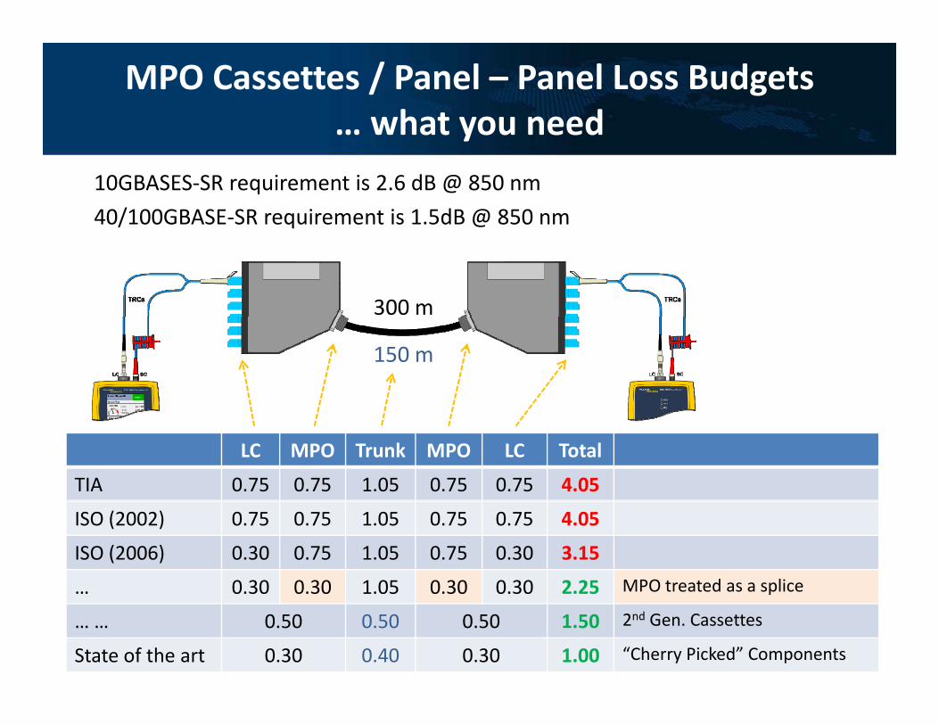
MPO Cassettes / Panel – Panel Loss Budgets… what you need… what you need
10GBASES‐SR requirement is 2.6 dB @ 850 nm
40/100GBASE‐SR requirement is 1.5dB @ 850 nm
300 m
/ q @
150 m
LC MPO Trunk MPO LC Total
TIA 0.75 0.75 1.05 0.75 0.75 4.05
ISO (2002) 0.75 0.75 1.05 0.75 0.75 4.05
ISO (2006) 0.30 0.75 1.05 0.75 0.30 3.15
0 30 0 30 1 05 0 30 0 30 2.25 MPO treated as a splice… 0.30 0.30 1.05 0.30 0.30 2.25 MPO treated as a splice
… … 0.50 0.50 0.50 1.50 2nd Gen. Cassettes
State of the art 0.30 0.40 0.30 1.00 “Cherry Picked” Components

Low Loss MPO …The Drivers
• “Zoned Data Centers”
Distributor in accordance with ISO/IEC 11801
Network access cabling system
Main distribution cabling system
Zone distribution cabling system
Equipm. cabling
ISO/IEC 11801
Courtesy: TE Connectivity

Testing ‐ “Zoned” Data Centersg• After the installation only the links can be testet
• The “Patched Channel” is configured by the network user• The Patched Channel is configured by the network userLink Test #1 Link Test #2 Link Test #3
ChannelChannel
• A common mistake is to test a links to channel limits
• Correct is to certify compliance with the link limit
Courtesy: TE Connectivity
• Correct is to certify compliance with the link limitand/or compliance with component limits

Testing a Complex Channel
• Assumptions:C l l i ti f 4 t
g p
– Complex cannel consisting of 4 segments
– One connection is very poor (1.00dB)
– All other connections 0.25dB and fiber 3.0dB/km
Conn.#1
Fiber #1
Conn. #2
Fiber #2
Conn.#3
Fiber #3
Conn. #4
Fiber #4
Conn. #5
Total
L (m) 30 30 30 30 120L (m) 30 30 30 30 120
0.30 0.105 0.75 0.105 0.75 0.105 0.75 0.105 0.30 2.40
Value 0.25 0.09 0.25 0.09 0.25 0.09 1.00 0.09 0.25 2.32
Take Away:Take Away:• Tier1/BASIC LSPM Testing: The good connections may cover up for
one very poor one
Take Away:Take Away:• Tier1/BASIC LSPM Testing: The good connections may cover up for
one very poor oneone very poor one • Only an OTDR can find the “unnecessary bottle neck
one very poor one • Only an OTDR can find the “unnecessary bottle neck

Testing a Complex Channel
• Assumptions:C l l i ti f 4 t– Complex cannel consisting of 4 segments
– One connection is very poor (1.00dB)
– All other connections 0.25dB and fiber 3.0dB/km
Conn.#1
Fiber #1
Conn. #4
Total
L (m) 30 30
Conn.#1
Fiber #1
Conn. #4
Total
L (m) 30 30L (m) 30 30
0.30 0.105 0.30 0.70 1)
Value 0.25 0.09 1.00 1.34
L (m) 30 30
0.75 0.105 0.75 1.605
Value 0.25 0.09 1.00 1.34
Take Away:Take Away: PASS//FAIL FAIL based on the length depended link budget will flag bad connectors.
Take Away:Take Away: PASS//FAIL FAIL based on the length depended link budget will flag bad connectors.
Take Away: Take Away: OTDR OTDR PASS//FAIL FAIL testing should be based on component limits. More generous component limits
Take Away: Take Away: OTDR OTDR PASS//FAIL FAIL testing should be based on component limits. More generous component limits
The OTDR will allow to identify the poor end and which cassette to swap/connector inspect and clean
The OTDR will allow to identify the poor end and which cassette to swap/connector inspect and clean
make the information valuable even before computing the accurate average
make the information valuable even before computing the accurate average

Can OTDRs PASS/FAIL a link based on a length dependent limits ?length dependent limits ?
• This function is common in LSPMs (Light Source and power meters)
• Directivity and tight ISO or even tighter project specific li i k hi f i l d i bl f OTDRlimits makes this function also desirable for an OTDR
• The time saving is significant > 50%
• Such a function in an OTDR will not obsolete LSPMs because
th ill l id th t t l– they will always provide the most accurate loss measurement
– They are less expensive and often considered to be easier to y puse

OTDR PASS/FAIL Based on a Length Dependent Link Limit
- 0.23 dB
0.33 dB
+ 0.44 dB
Automatic Limit Calculation for OTDR Automatic Limit Calculation for OTDR PASS//FAIL FAIL testing:First Connector 0.30 dB
Automatic Limit Calculation for OTDR Automatic Limit Calculation for OTDR PASS//FAIL FAIL testing:First Connector 0.30 dBFiber 50.49*3.5/1000 = 0.18 dBLast Connector 0.30 dB
Total 0.78 dB
Fiber 50.49*3.5/1000 = 0.18 dBLast Connector 0.30 dB
Total 0.78 dB

Bi‐Directional OTDR Tests Without a Tail Fiber
- 0.23 dB
0.33 dB 0.32 dB
+ 0.44 dB - 0.20 dB

Testing Of Parallel Optics Based Cabling Infrastructureg
MPO / MPT

Fiber Inspection
• Equipment exists for inspecting MPO connectors

Polarity ‐MPO/MTP System Type A
26
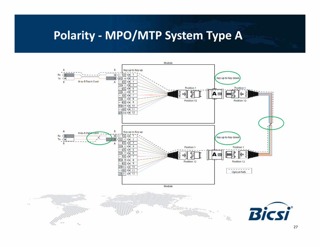
Polarity ‐MPO/MTP System Type A
27

Polarity ‐MPO/MTP System Type B
Tech Forum "Verkabelung – Netze – Infrastruktur" 28

Polarity ‐MPO/MTP System Type B
29

Polarity ‐MPO/MTP System Type C
Tech Forum "Verkabelung – Netze – Infrastruktur" 30

Polarity ‐MPO/MTP System Type C
31
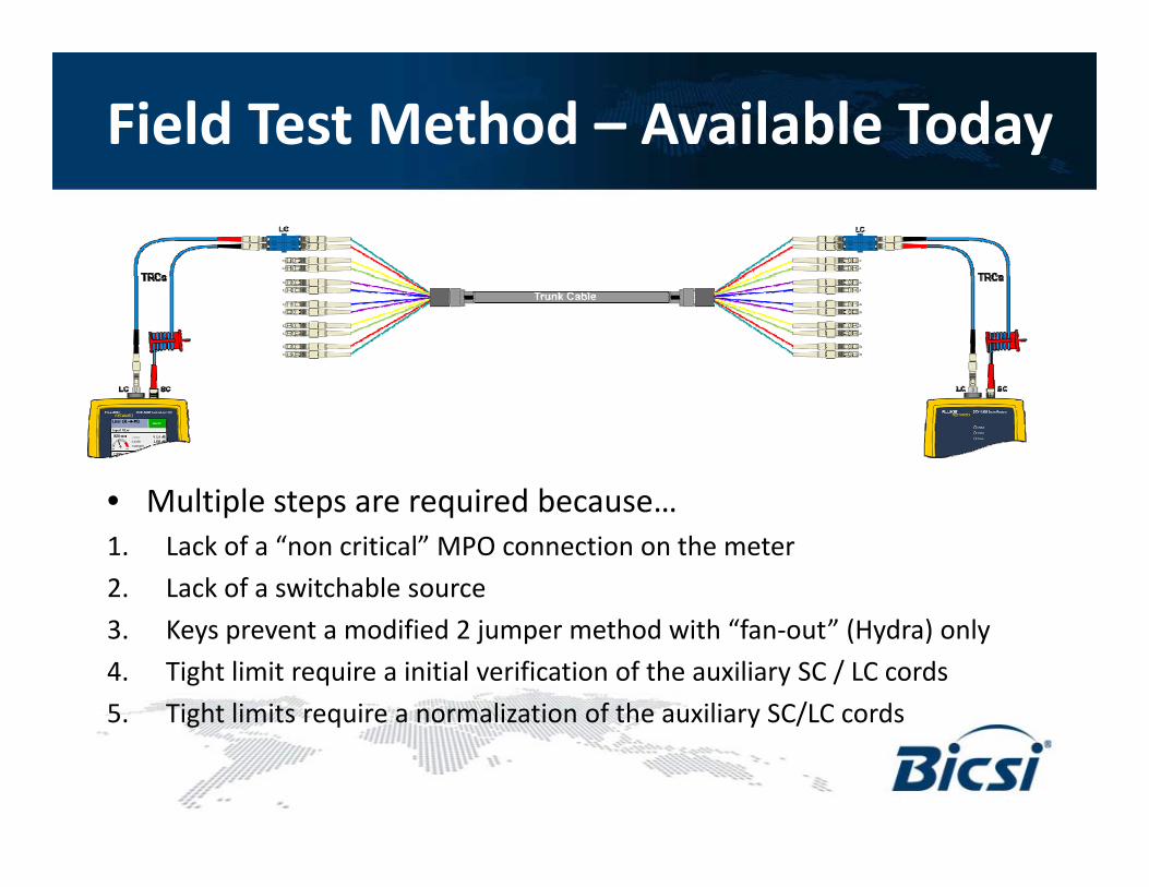
Field Test Method – Available Today
• Multiple steps are required because• Multiple steps are required because…1. Lack of a “non critical” MPO connection on the meter
2. Lack of a switchable source
3. Keys prevent a modified 2 jumper method with “fan‐out” (Hydra) only
4. Tight limit require a initial verification of the auxiliary SC / LC cords
5. Tight limits require a normalization of the auxiliary SC/LC cordsg q y /

MPO Field Tester – Wish List
1. Testing of all fibers in the link in one go
2. Non critical MPO connector on the meter to support the most accurate one jumper method
3. Switchable MPO source to verify polarity – System A, B, C, ….
– Field terminated connectors
4. MPO Test Reference Cords with reference grade connectors– A definition for reference grade MPO connectors !

Conclusio
St d d b d li it t b d t t t i t ll ti• Standards based limits can not be used to test an installation– Test needs to be based on limits agreed by the supplier,
customer/consultant and the installer
– Procedures for testing and setting the reference need to be agreed on by
• Test cords (Fan Out) will be specific for the project( ) p p j
• Attention needs to be paid to cleaning and inspection
• Complex channels constructions can only be supported with components exceeding the normative requirements


