FIELD SAMPLING PLAN FOR HOMESTAKE MINING ... SAMPLING PLAN Homestake Mining Company Superfund Site...
45
FIELD SAMPLING PLAN Homestake Mining Company Superfund Site Grants, New Mexico Prepared August 2010 Prepared for EPA Region Six Prepared by USACE Kansas City District Hazardous, Toxic, and Radioactive Waste Program Radiation Safety Support Team llllllllllllllllllllllllllllllllllllllll 662878 000086
Transcript of FIELD SAMPLING PLAN FOR HOMESTAKE MINING ... SAMPLING PLAN Homestake Mining Company Superfund Site...
FIELD SAMPLING PLAN
Homestake Mining Company Superfund Site Grants, New Mexico
Prepared August 2010
Prepared for EPA Region Six
Prepared by USACE Kansas City District Hazardous, Toxic, and Radioactive Waste Program Radiation Safety Support Team
llllllllllllllllllllllllllllllllllllllll 662878
000086

Table of Contents
1.0 Project Background 1.1 Site History and Contaminants 1.2 Site Description 1.3 Contaminants of Potential Concern 1.4 Summary of Existing Site Data
2.0 Project Organization and Responsibilities · 2.1 EPA Responsibilities 2.2 USACE Responsibilities
3.0 Project Scope and Objectives 3.1 Applicable Regulations/Standards 3.2 Project Schedule
4.0 Field Sampling Plan 4.1 Survey Guidance 4.2 Action Levels 4.3 Survey Methods and Techniques 4.4 Sampling Procedures 4.5 Background and Reference Areas 4.6 Soil Sampling 4.7 Vegetation Sampling 4.8 Water Sampling 4.9 Radon Sampling 4.10 Film Sampling 4.11 Sample Handling and Storage 4.12 Survey Questionnaire
5.0 Field Operations Documentation 5.1 Daily Quality Control Reports (QCR) 5.2 Field Survey Documentation 5.3 Photographic Records 5.4 Sample Identification 5.5 Chain-of-Custody Records
6.0 Investigation Derived Waste Management 7.0 Field Assessment/ Inspection Procedures
7.1 Field Instruments 7.2 Quality Control Chart 7.3 Instrument Contamination
8.0 Nonconformance/Corrective Actions 9.0 Phase 3 Work
9.1 GPS Walkover Gamma Surveys 9.2 Downhole Gamma Logging (DHG)
10.0 EPA ERGS Vehicle Scanning 11.0 References
Appendix A- Project Documents
000087

Appendix B- Sampling SOPs
2
000088

1.0 Project Background The purpose of this survey and sample investigation is to acquire the data necessary to perform a Human Health Risk Assessment (HHRA) to address community concerns related to the Homestake Uranium Mine. This survey and sampling effort will be performed by the US Army Corps of Engineers (USACE) Kansas City District.
Residents live across the road from the Homestake Mining Co at a distance of approximately 0.5 miles from the current on-site groundwater remediation project. The public is concerned that they are being exposed to unacceptable levels of radioactive contaminants through the inhalation and ingestion routes of intake. They alleged that the contaminants are transported into their homes through the spray mist from the evaporation ponds associated with the ground water remediation activities, through emissions from the tailing piles, through emissions from the land application, and through their use of contaminated ground water for domestic uses (such as cooking, showering, washing, etc.). They also showed concern from consumption of produce in areas irrigated with contaminated ground water and consumption of livestock meat exposed to ground water in the area.
To address public concerns, soil samples from yards and fields, garden vegetables (root and above ground vegetables), hay or grass grown in grazing fields, water from garden hoses, water from bins used for livestock, indoor and outdoor radon gas samples, soil samples from center pivot irrigated areas and flood irrigated areas need to be collected. Sample collection will be performed in three Phases, which are discussed in more detail in the following sections. The data will then be used to develop a screening Human Health Risk Assessment. The objectives of the assessment are to characterize and quantify where appropriate, the current and potential human health risks that would prevail if no further action is taken.
1.1 Site History and Contaminants The Homestake Mining Company uranium mill opened in 1958 and is located 5.5 miles north of the Village of Milan in northwest New Mexico.
In 1958, milling operations began at Homestake's mill site. The operations involved the use of an alkaline leach-caustic precipitation process to extract and concentrate uranium oxide from uranium ores. The byproducts (waste) were either disposed above ground in the two tailings impoundments or recycled back into the milling process. For approximately 30 years, Homestake milled uranium at the site.
Homestake began a state-approved groundwater restoration program in 1977. The program consists of a groundwater collection/injection system for the San Mateo alluvial aquifer and the Upper and Middle Chinle aquifers. The objective is to reduce contaminant concentrations down to background concentrations.
In September 1983, USEPA placed the Homestake site on the National Priorities List (NPL), primarily because of groundwater contamination. Further investigations at the site identified groundwater contamination in on-site monitoring wells and some residential wells. Homestake
3
000089

and the USEPA signed a consent decree in December 1983. The decree required Homestake to provide an alternate water supply to nearby residences and to pay for water usage for 10 years. The alternate water supply connections to residences were completed in April1985, with Homestake paying for water usage until 1995. The soil cleanup and mill reclamation activities were completed in 1995 and approved by the NRC in 1999.
In 1990, the mill closed and was decommissioned and demolished. During 1993-1995, the Nuclear Regulatory Commission (NRC) supervised surface reclamation activities at the site. Although the mill is gone, two tailings pilesremain. The tailings piles are the result of waste products generated from the milling of uranium. The larger pile covers approximately 175 acres and is approximately 100 feet high; the smaller pile covers 40 acres and is 25 feet high.
In September 2005, the New Mexico Environment Department (NMED) and USEPA conducted a well survey in the residential subdivisions south of the mill site to verify that residents were not being exposed to contaminated well water. These two agencies collected samples from 34 private water supply wells. The samples were analyzed for USEPA's target analyte list of compounds and radionuclides. In November 2005, USEPA Region 6 contacted the Agency for Toxic Substances and Disease Registry (A TSDR) and requested that A TSDR review the results and determine whether a public health hazard exists. Additional sampling was conducted in 2006 and 2007. .
In 2009 A TSDR published a Health Consultation Report based on their review of the water supply well sample data. A TSDR calculated exposure doses for the contaminants above health comparison values and MCLs in well sample results and determined that those being used as a source of potable water were not at levels that would produce known adverse health effects. The report did identify a few wells that have uranium concentrations well above the background concentration that were not being used and recommended that they should not be used.
1.2 Site Description
1.2.1 Location The Homestake Mining Company Site is located approximately 5.5 miles north of Milan, in Cibola County, New Mexico. The site has two tailings piles, a groundwater treatment facility, and two existing evaporation ponds. The large tailings pile is unlined, covers approximately 175 acres, is 95-100 feet tall, and contains approximately 20 million tons of tails. The small tailings pile is also unlined and covers approximately 40 acres, is 25 feet tall, and contains approximately 2 million tons of tails. The tailings piles overlie an alluvial groundwater aquifer, into which contaminants from the piles have migrated
4
000090

1.2.2 Hydrogeology The tailings piles are located on alluvium, which is unconsolidated soil or sediment deposited by a river or other flowing water. The alluvium overlies the Chinle and San Andres aquifers, which subcrop with the alluvial aquifer at various locations near Homestake. Radioactive and nonradioactive contaminants within the tailings piles have leached and seeped downward through the soils, beneath the tailing piles into the groundwater. Mixing to some extent between the different aquifers does take place naturally via faulting and subcropping.
There are two faults, the East Fault and the West Fault, that exist within the Chinle and these alter the groundwater flow direction. Between the East and West Faults (underlying most of the Homestake site), flow is south to north, while west of the West Fault and east of the East Fault, Middle Chinle groundwater flow is north to south. All three Chinle aquifers subcrop with the overlying alluvial aquifer. In the areas where the Chinle subcrops with the alluvium, the area has been defined as a Chinle mixing zone (Hydro-Engineering 2001). The majority of the Upper Chinle mixing zone in the vicinity of the Homestake site occurs between the East and West
·Faults.
5
000091

Groundwater monitoring data indicate that contamination from tailings seepage at the mill site has potentially affected the San Mateo alluvial aquifer and the Upper, Middle, and Lower Chinle aquifers. The San Mateo alluvial aquifer is the primary aquifer of concern because it is the most contaminated, and it recharges the Chinle aquifers, which nearby residents have used as a source of drinking water.
1.2.3 Population Five residential subdivisions are located south and southwest of the mill site: Felice Acres, Broadview Acres, Murray Acres, Valle Verde, and Pleasant Valley Estates, along with a few residences located near the Pleasant Valley Estates. Within the subdivisions and farther south and west, the land is used for agriculture and livestock. The subdivisions are located between 0.5 mile to 2 miles from the tailings piles, with the nearest residence and drinking water well about 3,000 feet away. The private well sample results are from the above five subdivisions and several residences east of State Route 605 that are located southeast of the mill site.
1.3 Contaminants of Potential Concern
1.3.1 Radionuclides
1.3.1.1 Uranium Natural uranium consists of three major isotopes: uranium-238 (99.28% natural abundance), uranium-235 (0.71 %), and uranium-234 (0.0054%). All three are radioactive, emitting alpha rays. Uranium-238 is the most stable isotope, with a half-life of 4.468 x 10⁹ years. Uranium-235 has a half-life of 7.13 x 10⁸ years, and uranium-234 has a half-life of 2.48 x 10⁵ years. In natural . uranium, about 49% of the alpha rays are emitted by each of238U and 234U and about 2% by the 2350.
Normal functioning of the kidney, brain, liver, heart, and other systems can be potentially affected by uranium exposure, because, besides being weakly radioactive, uranium is a toxic metal. Uranium is also a reproductive toxicant. Radiological effects are generally local because alpha radiation, the primary form ofU-238 decay, has a very short range, and will not penetrate skin.
1.3.1.2 Radium Radium is a decay product of uranium and is therefore found in all uranium-bearing ores. The various isotopes of radium originate from the radioactive decay of uranium or thorium. Radium-226 is found in the uranium-238 decay series, and radium-228 and -224 are found in the thorium-232 decay series.
Radium-226,. the most common isotope, is an alpha emitter, with accompanying gamma radiation, and has a half-life of about 1600 years. Radium-228 is principally a beta emitter and has a half-life of 5.76 years. Radium decays to form isotopes of the radioactive gas radon.
1.3.1.3 Thorium Naturally occurring thorium is composed mainly of one isotope: 232Th. 230Th occurs as the daughter product of238U decay. Thorium-232 has a half-life of 14 billion (14x109
) years, and
6
000092

decays by alpha emission, with accompanying gamma radiation. Thorium-232 is the top of a long decay series that contains key radionuclides such as radium-228, its direct decay product, and radon-220. Two other isotopes of thorium, which can be significant in the environment, are thorium-230 and thorium-228. Both belong to other decay series. They also decay by alpha
. emission, with accompanying gamma radiation, and have half-lives of75,400 years and 1.9 years, respectively.
1.3.2 Metals
1.3.2.1 Selenium Selenium is a naturally occurring, solid element that is widely but unevenly distributed in the earth's crust. Selenium is an essential nutrient for humans and animals. In some parts of the United States, especially in the western states, some soils naturally contain high levels of selenium compounds. Still, no human populations in the United States have been identified with long-term selenium poisoning, including populations in the western part of the country where, as stated, in-soil selenium levels are naturally high. Most of the selenium that enters the body quickly leaves, usually within 24 hours. Some studies have shown that if mildly excessive amounts of selenium are eaten over long periods, brittle hair and deformed nails can develop
1.3.2.2 Molybdenum Molybdenum does not occur as the free metal in nature, but rather in various oxidation states in minerals. Molybdenum dusts and fumes, as can be generated by mining or metalworking, can be toxic, especially if ingested. Low levels of prolonged exposure can cause irritation to the eyes and skin. Direct inhalation or ingestion of molybdenum and its oxides should be avoided
1.3.2.3 Vanadium Vanadium is a soft, ductile, silver-gray metal. It has good resistance to corrosion and it is stable against alkalis, sulfuric and hydrochloric acids. Metallic vanadium is not found in nature, but is known to exist in about 65 different minerals. All vanadium compounds should be considered to be toxic.
1.3.2.4 Arsenic Arsenic is an element that occurs naturally in soil and minerals and is widely distributed in the earth's crust. It may enter the air, land and water from windblown dust and may also enter the water from runoff and leaching. In the environment, arsenic usually bonds with other elements such as oxygen, chlorine, and sulfur. This form of arsenic is known as inorganic arsenic. Arsenic combined with carbon and hydrogen is known as organic arsenic. The organic forms of arsenic are usually less harmful than the inorganic forms.
1.3.2.5 Lead Like arsenic, lead is a naturally occurring element and is a known toxin. But unlike arsenic, lead is bluish-gray in color and occurs in smaller quantities in the earth's crust. The main target for lead toxicity in both adults and children is the nervous system. Children, however, are more sensitive to the effects of lead than are adults. Low levels of lead exposure can affect children's mental and physical growth.
7
000093

1.4 Summary of Existing Site Data
1.4.1 Homestake NRC Surveys Homestake routinely collects and analyzes air samples at the site boundary (for radon and evaporation pond constituents of concern) in accordance with NRC license requirements. In addition Homestake collects soil samples in the irrigated areas and vegetation samples from the irrigated fields to aid in demonstrating the effects of land application. The land application is not regulated by the NRC license.
1.4.2 EPA ERGS Rig Survey Prior to USACE Phase 2 survey efforts, EPA Region 6 will perform a surface gamma scan using the EPA's ERGS gamma scanning vehicle. More discussion of this survey is detailed in Section 10.
8
000094

2.0 Project Organization and Responsibilities
2.1 EPA Responsibilities EPA Region Six will provide project funding and project coordination and guidance for survey efforts.
EPA Region Six will be responsible for securing laboratory services and will serve as the point of contact for laboratory correspondence.
EPA Region Six will acquire access agreements required to complete the sampling and survey effort and for scheduling and coordinating with landowners.
2.2 USACE Responsibilities USACE Kansas City District will be responsible for developing all project work plans, to include Field Sampling Plan, Health and Safety Plan (HASP) and Quality Assurance Project Plan (QAPP)
USACE Kansas City District will serve as the project health physics support and coordinator of field work to include preparation of plans and preparation of final reports.
USACE Kansas City District will perform the Phase 1 and Phase 2 field work as described in Section 3.2.2.
USACE Kansas City District will be responsible for securing an appropriate analytical laboratory for all samples which will not be sent to the designated EPA laboratory.
USACE Kansas City District will be responsible for acquiring a radiological services contractor to perform follow on survey work to be performed; to include GPS assisted gamma walkover surveys, downhole gamma logging, and soil gas sampling
USACE Kansas City District will review all field and laboratory data to ensure it meets the requirements of this work plan and the associated Quality Assurance Project Plan (QAPP).
USACE Kansas City District will be responsible for communicating and field changes or deviations to EPA Region Six and for documenting any changes or other occurrences as required by this document and the associated QAPP.
9
000095

3.0 Project Scope and Objectives The objectives of this field effort are to obtain enough data of sufficient quality to develop a screening Human Health Risk Assessment (HHRA). The work will be performed in three phases. Two phases will consist ofUSACE field work as outlined in Section 3.2.2. Phase 3 follow on work, to include GPS assisted gamma walkover surveys of residences and background areas, downhole gamma logging, and soil gas sampling will be performed by a to be determined radiological services contractor and is summarized in Section 10.
3.1 Applicable Regulations/Standards The uranium mill was in operation from 1958 to 1990 and was originally licensed by the Atomic Energy Commission.
On December 14, 1993, the NRC and the EPA signed a memorandum of understanding (MOU) delineating agency responsibilities in regulating activities at the Homestake Mining Company.
Homestake Mining Company currently meets the NRC emission criteria. However, EPA is conducting this study independently to ensure compliance with CERCLA.
Air and groundwater monitoring is in place to ensure that U. S. Nuclear Regulatory Commission (NRC) standards are being met during the ongoing remedial activities. Homestake routinely collects and analyzes air samples at the site boundary (for radon and evaporation pond constituents of concern) in accordance with NRC license requirements. In addition Homestake collects soil samples in the irrigated areas and vegetation samples from the irrigated fields to aid in demonstrating the effects of land application. The land application is not regulated by the NRC license
3.2 Project Schedule
3.2.1 Document Development
The Draft Work Plans, to include this document, a Quality Assurance Project Plan (QAPP) and Health and Safety Plan (HSP) will be completed by Kansas City District, USACE on 21 May 2010
The Final Work plans will be issued on 07 July 2010
Soil sample results will be compiled and a Letter Report will be prepared to document the survey results for both Phase 1 and Phase 2. Soil samples will be reanalyzed after a 21 day hold to allow for the in growths of short lived Radium daughter products, and these results will be used to draft a Final Report.
A draft Final Status Survey Report will be prepared within 30 days of completion of both Phase 1 and Phase 2 surveys. The draft will be presented to all parties receiving the draft plan for comment. Comments will be requested 30 days after receipt of report.
10
000096

3.2.2 Field Activities USACE performed field work in this project will be conducted two phases, one in the summer of 2010 and one in the winter of2010. A third phase will be performed by a radiological services contractor at a time to be determined.
The US ACE field survey team will arrive at the project site in September of 2010 to perform Phase 1 activities. Phase 1 activities will include the following tasks -
Phase 1 Tasks- September 2010 Place indoor alpha track detectors in background homes Place indoor alpha track detectors in potentially affected area homes Place outdoor alpha track detectors in identified background areas Place outdoor alpha track detectors in identified potentially affected areas Perform home interior radiation survey in potentially affected area homes Collect home information survey (if mailed prior to Phase 1) Collect vegetation samples from potentially affected area homes Collect water samples from background area homes Collect water samples from potentially affected area homes Collect systemic soil samples at identified background areas Collect systemic soil samples at identified potentially affected areas Collect water samples from evaporation pond area If discovered, collect water samples from animal water tanks If discovered, collect wipe samples of spray mist film from the potentially affected area
The field survey team will arrive at the project site in the winter of 2010 to perform Phase 2 activities, which will include the fo(lowing tasks -
Phase 2 Tasks- Winter 2010 Place indoor charcoal detectors in background homes Place indoor charcoal detectors in potentially affected area homes Place outdoor charcoal detectors in identified background areas Place outdoor charcoal detectors in identified potentially affected areas Collect judgmental soil samples from Central Pivot area based on results from ERGS . survey
A radiological services contractor will be acquired by either the USACE or by EPA Region 6 to perform Phase 3 work. A more detailed discussion of these activities is available in Section 9. Phase 3 activities will consist of the following tasks -
Phase 3 work performed by Radiological Services Contractor- TBD Perform GPS walkover radiation survey of identified background areas Perform GPS walkover radiation survey of potentially affected area homes Collect soil samples based on walkover survey results from potentially affected area homes
II
000097

Perform residential soil gas survey at identified potentially affected area homes Perform downhole gamma logging at identified potentially affected area homes
12
000098

4.0 Field Sampling Plan
4.1 Survey Guidance Guidance from the Multi-Agency Radiation Survey and Site Investigation Manual (MARSSIM) will be utilized in the design, implementation, and data interpretation for this survey effort.
The MARSSIM process was developed collaboratively by the NRC, EPA, DOE, and U.S. Department of Defense, for use in designing, implementing, and evaluating radiological surveys. This process emphasizes the use ofEPA's data quality objectives (DQOs) and data quality assessment processes, along with a sound quality assurance/quality control program. The graded approach concept is also used to ensure that survey efforts are maximized in those areas where there is the highest probability for residual contamination or greatest potential for adverse impacts of contamination. Implementation of this graded approach is incorporated throughout the MARSSIM process.
The MARSSIM process also embodies flexibility to allow. adaptation of guidance to be responsive to specific site situations and agency objectives and requirements.
The EPA will also use the same guidance references as used for hazardous chemicals in its investigation on the impact of site specific chemicals and radionuclides on human health and the environment.
4.2 Action Levels Final action levels for site soil based on excess cancer risk will be developed after the risk assessment is finalized. Action levels based on excess cancer risk based on default exposure values as calculated by EPA's PRO calculator under a residential scenario, which considers exposure through soil ingestion, inhalation, consumption of fruits and vegetables, and external exposure, are as follows-
Soil concentrations in pCilg associated with excess lifetime cancer risk lE-04 to lE-06. 10-" 10-::l 10-b
Uranium-238 + D 74.2 7.42 0.742 Radium-226+D 1.2 0.12 0.012 Radium-226 19.3 1.93 0.193 Radium-228 +D 3 0.3 0.03 Radium-228 26 2.6 0.26 Thorium-238 350 35 3.5
Soil samples will also be screened against the site wide soil criteria to prevent long-term exposure to thorium and radium contaminated material (e.g., soil), with concentrations greater than 5 pCi/g above background. Background soil concentrations will be determined as part of this investigation. As the radionuclides of concern for this site are radium-226 (Ra-226), Ra-228, thorium-230 (Th-230) and Th-232, the soil criteria are the following:
Ra-226 + Ra-228 < 5 pCi/g above background.
13
000099

Th-230 + Th-232 < 5 pCi/g above background.
For the metals of concern the preliminary remediation goals for residential soil exposure through the ingestion, inhalation, and dermal contact pathways based on national soil screening levels and default exposure parameters are as follows-
Soil concentrations (mg/Kg) associated with cancer and non-cancer risk from exposure to "I th h th . f . h I t" d d I t t "th "I SOl roug1 e mges 1on, m a a 1on an erma con ac WI SOl.
Cancer Risk (1E-06) Non-Cancer Risk (HQ = 1) Arsenic 0.39
Molybdenum 390 Selenium 390
Lead 150-400 Uranium 230
Vanadium 390
It should be noted that data collected during this investigation are compared to a variety of different action levels in order to make appropriate decisions regarding property classification and to determine what additional measurements or sampling may be required.
For interior and exterior residential building material surveys, an action level of 11Rfhr above · background will be used to indicate areas of potential concern that may require additional investigation. ·
Action levels for survey instruments will be calculated using MARSSIM methodology, primarily outlined in MARSSIM Chapter Six.
For this survey effort, an action level is defined as the level at which instrument readings indicate small areas of potential concern. It's important to note that a reading that exceeds an instrument action level is not necessarily indicative of the presence of contamination. Rather, it should be considered to represent an area that may warrant further investigation.
The two types of action levels used in this survey will be the Scan Sensitivity, or Minimum Detectable Count Rate (MDCR), and the Critical Level (Lc)
4.2.1 Scan Sensitivity!MDCR The Scan Sensitivity, or Minimum Detectable Count Rate (MDCR), is the count rate, above background which an instrument can be considered to be able to reliably and routinely detect with a predetermined level of confidence. This level will be set as the investigation level for scanning for this survey. Elevated activity areas identified during scanning will be further investigated and potentially assigned as additional sample locations. Scanning Sensitivity (MDCR) values are dependent on background levels and will be determined in the field using the below calculations from MARSSIM Chapter Six.
14
000100

S;= minimum detectable # of net counts in the observation interval. d'= from Table 6.5 in MARSSIM based on acceptable error rate decisions b; = number of background counts in the interval.
For this survey effort a type I error rate of 0.05 and a type II error rate of 0.6 will be used. From MARSSIM table 6.5 the value of d' is thus 1.38. The surveyor performing the scanning will ensure that scan speeds are adequate and that observation intervals over each scanned area are approximately one second. The above equation is then given as -
S;= minimum detectable net counts in the observation interval b= number ofbackground counts per minute
The result from the above equation is used to calculate the Minimum Detectable Count Rate using the following equation.
MDCR =siX c6J{) MDCR = minimum detectable count rate. S; = minimum detectable # of net counts in the observation interval. i = time interval = 1 second
Given that a time interval of one second has been chosen, this equation reduces to -
MDCR=S;x60 MDCR = minimum detectable count rate. S; = minimum detectable #of net counts in the observation interval.
Combining the two equations and simplifying yields a Scanning Sensitivity (MDCR) for an ideal observer of-
MDCR = 10.7x.Jb MDCR = minimum detectable count rate. b = number of background counts per minute
MARSSIM recommends using a surveyor efficiency value (p) to account the actual performance of a human surveyor. This survey efficiency is accounted for by dividing the MDCR by the square root of p. The surveyor MDCR is then calculated with the below equation -
MDCR = 10.7x.Jb
fP MDCR = minimum detectable count rate. b =number of background counts per minute p = surveyor efficiency
15
000101

For this project, a conservative surveyor efficiency of0.5 is assumed. The final calculation for the instrument MDCR is given below
MDCR= I0.7 xJb =15.IxJb JiU
MDCR = minimum detectable count rate. b =number of background counts per minute
A spreadsheet with these calculations will be used by the field team to determine and record the instrument Scan Sensitivity. A copy of this spreadsheet is included in Appendix A
4.2.2 Minimum Detectable Concentration Typical Scan Minimum Detectable Concentration (MDC) values for 2" x 2" sodium iodide (Nal) field scanning instruments can be found in Table 6.7 ofMARSSIM Chapter Six and are given below. These values are listed for reference only. Field decisions will be based on survey readings and the MDCR value calculated.
Radio nuclide Scan MDC (pCi/g) Ra-226 (in equilibrium with progeny) 2.81 Th-232 (In equilibrium with progeny in decay series) 1.8 Natural Uranium 80
4.2.3 Critical Level An action level for integrated measurements will be set at each instrument's critical level. This level is the counts at which there is a 95% probability that the measurement is above background, although it may not be able to be quantified reliably. Elevated activity areas identified during scanning will be investigated further with an additional survey and static counts, as appropriate. Evidence of elevated activity may results in a sample being taken from the location for laboratory analysis.
Instrument critical levels are dependent on background and thus must be determined in the field. A critical level is calculated using MARSSIM equation 6-6.
Lc = B + 2.33-JB
Lc = critical level B =number of background counts
A spreadsheet with this calculation will be used by the field team to determine and record the instrument Critical Level. A copy of his spreadsheet is included in Appendix A.
4.3 Survey Methods and Techniques When taking a soil sample, a one minute static count will be taken at each sample location prior to collection by placing the instrument on the ground at the location and allowing the instrument to integrate counts over the interval.
16
000102

For residential surveys, the interior of structures will be surveyed using a pressurized ion chamber (PIC) to determine exposure rates within dwellings. Survey readings will be compared to an investigation level of 5 f.!R/hour above regional background. If elevated readings are encountered the surveyor will determine whether the readings can be attributed to naturally occurring building material, or if additional surveying should be conducted.
4.4 Sampling Procedures Sampling efforts will follow the Standard Operating Procedures (SOPs) developed by EPA Region 4 and detailed in the Field Branches Quality System and Technical Procedures Guidance. The appropriate SOPs for all field efforts are included in Appendix B.
EPA Region 6 has developed a Conceptual Site Model and the Visual Sampling Plan model was used to calculate number of samples needed in this sampling event. A table outlining the type and number of samples collected during each phase of the project is provided below. Samples taken during Phase 1 and Phase 2 will be collected by USACE personnel. Samples taken during Phase 3 will be collected by a yet to be determined radiological services contractor.
Ph ase 1S I C II f ample 0 ec 10n- s ummer 2010 Matrix Samples QC MS Total
Background Surface Soil 30 3 2 35 Background Subsurface Soil 28 3 2 33 Background Residential Water 10 1 1 12 Background Indoor/Outdoor Radon 60 6 NA 66 (Alpha Track Etch Detectors) Vegetation 25 3 2 30 Residential Water 14 2 1 17 Animal water tanks Up to 10 1 1 12 Evaporation pond water Up to 10 1 1 12 Indoor/Outdoor Radon 80 8 NA 88 (Alpha Track Etch Detectors) Spray Film TBD TBD TBD TBD Total 305 Note that Indoor/Outdoor Radon momtonng will be attempted at all homes (approximately 145 homes).
Ph ase 2S I C II f ample 0 ec 10n- w· t 2010 mer Matrix Samples. QC MS Total
Background Residential Radon 60 6 NA 66
(Charcoal Canisters) Irrigation Area Surface Soil 20 2 1 23 Irrigation Area Subsurface Soil 20 2 1 23 Residential Radon
145 15 NA 160 (Charcoal Canisters) Total 271
Phase 3 Sam le Collection - TBD Matrix QC MS Total
Residential Surface Soil 8 4 85
17
000103

Residential Subsurface Soil and 40 4 2 46 gamma logging
Residential Soil Gas 12 2 1 15
Total 146
At least 10% of locations sampled will also be selected for duplicate QA/QC samples. This will require a duplicate sample taken from the sample location. Duplicate sample locations will be identified by the field team during the sampling effort. At least one duplicate sample will be collected for each media to be sampled.
At least 5% of locations sampled will also be selected for Matrix Spike (MS) QA/QC samples. This will require two additional samples taken from the sample location. MS,locations will be identified by the field team during the sampling effort. At least one MS sample will be collected for each media to be sampled.
4.5 Background and Reference Areas A background area is a non-impacted area that is representative of the materials in the potentially affected area with similar physical, geological, and radiological characteristics against which readings at residential sites may be compared. A reference or background location area for this project will be an area that may be rich in uranium in geologic formations but has never been mined. To establish a background area a reference community or locations will be identified and soil samples and radiological measurements will be taken. Crownpoint, NM and Bluewater, NM are two townships that have been identified as potential background reference areas. For sound statistical modeling, 30 residences will be identified and soil measurements will be collected for comparison against the Homestake subdivision residences. 10 of the 30 residences will also be sampled at depth to determine if instrument measurement readings increase or decrease with depth.
Radon and radon progeny measurements inside and outside of homes in the background area will also be taken for comparison to Homestake subdivision residences.
An appropriate background location for gamma scanning away from the spray mist will be determined during the initial site visit. The approximate location of the background area will be clearly noted on maps and in project records for future reference.
At least ten static one minute measurements will be taken in the background area to be used in calculations to determine the instrument Critical Level.
Background soil samples will be collected from the background area at locations considered similar to the soils that will be sampled from the residential areas. Additional background soil samples may be collected if the field survey team deems it necessary. The process for collecting soil samples is described in the Soil Sampling section below.
4.6 Soil Sampling A sampling team member will scrape a surface soil sample from each sample locations using a dedicated scoop; the appropriate volume from each location shall be placed into a stainless steel mixing bowl or a dedicated sample plastic bag and gravel and foreign matter will be discarded.
18
. I
000104

The sampling team member will use the spoon to thoroughly homogenize the sample material. The homogenized sample will be transferred directly into designated sample containers until the container is packed full.
Once a sufficient volume had been recovered, the sample container will be sealed, labeled, and placed into a sample shipping cooler. Clean Nitrile gloves will be worn by all personnel handling the s~mples.
4.6.1 Soil Sample Locations Systemic sample locations will be identified by EPA Region 6 using VSP or similar sample planning software. Prior to survey and sampling efforts, EPA Region 6 will provide a map with the locations of systemic soil samples to be collected.
4. 7 Vegetation Sampling Approximately 25 vegetable and alfalfa samples will be collected from area residential gardens and irrigation areas. A sampling team member will remove the required amount of vegetable qr alfalfa material from the identified area. The sample will be transferred directly into designated sample containers. ·
Once a sufficient volume had been recovered, the sample container will be sealed, labeled, and placed into a sample shipping cooler. Clean Nitrile gloves will be worn by all personnel handling the samples.
4.7.1 Vegetation Sample Locations Gardens that are sampled will be those that use or have used groundwater for irrigation. Sample locations will be chosen in patches that will be representative of the garden and that will be minimally intrusive to the garden's owner.
Once a sufficient volume had been recovered, the sample container will be sealed, labeled, and placed into a sampl'e shipping cooler. Clean Nitrile gloves will be worn by all personnel handling the samples.
4.8 Water Sampling Fourteen garden hose water samples from residents that use ground water for irrigation will be collected. One water sample will be taken from any waters bins used by domestic animals (cattle, horses or goats) encountered during the survey. Up to ten residences in background or reference communities that use private wells for indoor or outdoor use will also be sampled.
To collect a sample a sampling team member will draw an appropriate amount of water from the hose, allowing the hose to run for several seconds before collecting the sample to allow for any residual water in the hose to be removed. Once a sufficient volume had been recovered, the sample container will be sealed, labeled, and placed into a sample shipping cooler. Clean Nitrile gloves will be worn by all personnel handling the samples.
Water samples will be taken from stock tanks used by domestic animals if encountered. A -maximum often water stock tank samples will be taken. Stainless steel measuring cups or other
19
000105
similar containers will be used to draw sample water from the area. Once a sufficient volume had been recovered, the sample container will be sealed, labeled, and placed into a sample shipping cooler. Clean Nitrile gloves will be worn by all personnel handling the samples.
Water samples from any evaporation pond encountered will be sampled. A maximum of ten evaporation pond samples will be collected. Stainless steel measuring cups or other similar containers will be used to draw sample water from the area. Once a sufficient volume had been recovered, the sample container will be sealed, labeled, and placed into a sample shipping cooler. Clean Nitrile gloves will be worn by all personnel handling the samples.
4.8.1 Water Sample Locations Water samples from garden hoses, water bins, and evaporation ponds will be taken from locations that currently or historically have used groundwater domestically or for irrigation or other agricultural purposes.
4.9 Radon Sampling The impact of radon gas (Rn-222) on the Homestake residential subdivisions will be investigated. A previous radon study (EPA, 1989) and radon measurements have shown that residences in the subdivisions had been potentially impacted, sometimes with levels of radon exceeding the USEP A action level of 4 pCi/1. In this study EPA will try to get more information on the potential sources of radon gas. Indoor air samples will be collected using the short term (charcoal canisters) Rn-222 samples collected over 7 to 14 days in the winter months and long term (alpha track etch detectors) samples collected quarterly for a year. Outdoor air samples will also be collected using the alpha track etch detectors. Radon progeny will also be measured using working level (WL) monitors An attempt will be made to determine a site specific radon and progeny equilibrium factor both indoors and outdoor.
Track etch detectors will be placed in the yards of residences closest to the fence line with HMC. Two Track etch detectors will be placed on each post. One nailed to the post at 6" above the ground and the other nailed at about 5.5 feet above the ground. Another set of track etch detectors (3 detectors at any one location) will be placed on a line North East from HMC facility down to the residential subdivision south and southwest ofHMC. Track etch detectors will be properly calibrated to allow measured data to be converted to the true concentrations of radon as measured onsite.
A background community will be selected to represent a community similar to the HMC subdivision but was not mined before. Indoor radon samples will be collected using charcoal canisters and track etch detectors. Outdoor radon samples will be collected from the residential yards using track etch detectors. Surface soil (0-6") and soil at depth will be collected and tested for all COCs. Water from private wells will also be collected.
Site and background data will be compared using statistical tools to determine if onsite data is significantly higher than local background levels.
For properties with elevated indoor exposure rate scans, and where the short-term radon results are> 4 pCi/L or the measured Working Level (WL) is> 0.02 WL, downhole gamma logging
20
000106

will be collected and/or soil gas samples will be collected in a follow on investigation from just under the slab from outdoor locations or from locations just above ground water table or from crawl spaces.
Radon canisters will be placed in approximately 145 homes. Large homes and multistory homes may receive multiple canisters. Additional homes may be selected as background locations. The maximum number of canister samples planned for this survey event is 271.
4.9.1 Radon Sample Locations Canisters will be strategically placed inside the house to determine radon gas emitted from ground water used for domestic purposes such as showering, cooking, washing etc. Some canisters will be placed on the outside next to the entrance door. Canister locations will be recorded in order to facilitate recovery.
4.10 Film Sampling The Community is concerned that spray mist is blowing from the evaporation ponds onto residential property. The residents are reporting a film being deposited onto cars and request sampling to be conducted in the area potentially affected by the spray. When possible, a wipe sample will be taken of the film by wiping a wipe filter across approximately, 100 cm2 of the deposited film. These wipe samples will be sent to the contract laboratory for counting by Liquid Scintillation Counting, Gas proportional Counting, or an equivalent counting method. Deposited films will also be scraped and enough collected to attempt identify chemical forms of the films. 4.10.1 Film Sample Locations Location of spray mist film deposit samples will be identified by the field team during other survey efforts and documented in the field log book.
4.11 Sample Handling and Storage All samples will be handled carefully in accordance with the sampling SOPs located in Appendix B. Samples will remain in the custody of the field team at all times.
All samples will be stored in a designated cooler prior to sample shipment. There are no requirements for sample preservation except that, due to their nature, vegetation samples are to be shipped as soon as possible.
4.12 Survey Questionnaire A survey questionnaire will be developed to get personal and house specific information on the houses that will be sampled. Questions may include information on the type of house, the year built, the number of adults and children, use of private wells for indoor or outdoor purposes, whether a vegetable garden exist and domestic animals are raised, whether there was a transport of tailings to housing areas, indoor granite use, and methods ofventilation and heating of the residences.
21
000107

5.0 Field Operations Documentation
5.1 Daily Quality Control Reports (QCR) A summary of daily activities and any deviations from the project plans will be compiled daily and distributed to the appropriate project staff. The format of these reports is included in an example report enclosed in Appendix A.
5.2 Field Survey Documentation The following discussion outlines standard practices and procedures to be used when documenting a sampling episode. Proper completion of the logbook and supporting paperwork with indelible ink is necessary to support potential enforcement actions that may result from the sample analysis. Therefore, maintaining sample integrity through proper documentation is essentiaL
Project field logbooks must be bound and should have numbered and water-resistant pages. All pertinent information regarding the site and sampling procedures must be documented in indelible ink. Notations should be made in logbook fashion, noting the time and date of all entries. Information recorded in this logbook should include, but not be limited to, the following:
Name and exact location of site of investigation or interest
Date and time of arrival and departure
Names of all persons on site
Field instrument equipment used and purpose of use (i.e., health & safety screening, sample selection for laboratory analysis), calibration methods used, field results, and quality control(QC) information
Date and time of sample and data collection and any factors that may affect their quality
Weather conditions on the day of sampling, and any additional pertinent field observations.
5.3 Photographic Records Photographs of the work site will be taken and compiled with the field notes and presented in the final survey report.
5.4 Sample Identification A sample numbering system will be used to identify each sample collected and submitted for analysis. The purpose of this numbering system is to assist in tracking samples and facilitate retrieval of sample data. The sample identification numbers for each sampling effort will be used on sample labels, sample tracking matrix forms, chain of- custody forms, and all other applicable documentation. The sampling team leader will maintain a listing of all sample identification numbers in the field logbook. All sample containers will be labeled at the time of sampling.
22
000108
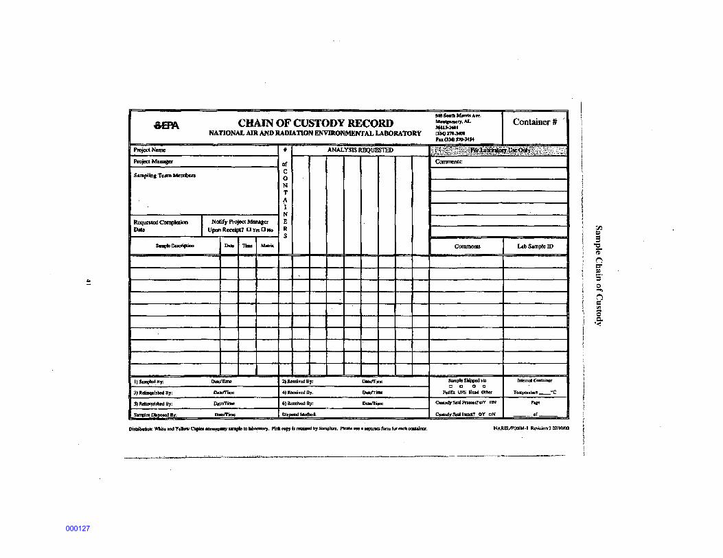
5.5 Chain-of-Custody Records Chain-of-custody procedures are employed to maintain and document sample possession. A sample is considered under a person's custody if it is in that person's physical possession, within visual sight of that person after taking physical possession, secured by that person so that the sample cannot be tampered with, or secured by that person in an area that is restricted to unauthorized personnel.
· Chain-of-custody records completed by the sampler will accompany all shipments of samples. Each cooler will have a chain-of-custody form listing the samples in the cooler.
It is possible that more than one chain-of-custody form will be needed per cooler to list all the samples contained in the cooler. The purpose of these forms is to document the transfer of a group of samples traveling together; when the group of samples changes, a new custody record is initiated. The original chain-of-custody record always travels with the samples; the initiator of the record keeps a copy.
The following procedures will be followed when using chain-of custody record sheets:
The originator will fill in all requested information from the sample labels.
The person receiving custody will check the sample label and tag information against the chain-of-custody form. The person receiving custody will also check sample condition and note anything unusual under "Remarks" on the chain-of-custody form.
The originator will sign the "Relinquished by" box and keep a copy of the chain-of custody form. After delivery by the commercial carrier, the person receiving custody will sign in the "Received by" box adjacent to the "Relinquished by" box (may also be filled in by recipient as "Federal Express" of other carrier name). All signatures and entries will be dated.
When custody is transferred to the analytical laboratory, blank signature spaces may be left and the last "Received by" signature box used. Another approach is to run a line through the unused signature boxes.
In all cases, it must be readily seen that the same person receiving custody has relinquished it to the next custodian. ·
If samples are left unattended or a person refuses to sign, this will be documented and explained on the chain-of-custody form
All samples will be shipped in a sealed cooler and will be maintained at or below 4°C using cold ice packs or ice packed in freezer bags when required by the receiving laboratory.
23
000109

6.0 Investigation Derived Waste Management Investigation-Derived Waste (IDW) in the form of waste PPE and decontamination materials such as paper towels will be generated as a result of the field activities for this project. PPE and other objects with potential surface contamination will be scanned using a Geiger-Mueller (GM) probe and instrument readings will be compared to the instruments critical level to determine whether or not the material has been impacted. If it is determined there is surface contamination, the material will be segregated as IDW.
When accumulated, the media must be managed appropriately to minimize the exposure to human health and the environment while adhering to applicable regulatory requirements. IDW material generated during project activities will be collected, containerized, and stored in an approved location prior to disposal.
It is not expected that significant quantities of contaminated soil or water waste will be generated during this field effort.
24
000110

7.0 Field Assessment/ Inspection Procedures
7.1 Field Instruments All field instruments used will have been properly calibrated by the manufacturer prior to use. Calibration records will be checked prior to instrument use.
The following routine checks will be performed on any instruments prior to use-
Perform battery check.
Check cables if broken or frayed.
Take background reading and ensure it's within chart parameters.
Perform quality control check on meters utilizing a source that emits the same radiation and approximate energy as that of the primary isotope of interest
7.2 Quality Control Chart Prior to the survey, all survey meters will be calibrated and have valid calibration certificates, and if possible, operability checks noted in the instrumentation section. A Quality Control (QC) chart will be started.
The QC chart is created by obtaining 20 to 30 data readings with an appropriate check source. The mean and standard deviations for the instrument response will be calculated and plotted. The mean is assumed to be the "true" value. The values for the warning limits (2 sigma) and control limits (3 sigma) are then calculated. The graph will be used to plot the daily operability checks for survey meters operated in the integrate mode. The same procedure will be employed for analog meters. For some analog meters, warning limits may be set at 15% and control limits at 20% of the mean value.
If daily operability checks fall outside the warning limits (but inside the control limits), the operability check should be repeated. If the check falls outside the control limits again, the instrument will be removed from service until it is either repaired, recalibrated or the cause for the out of control reading is identified. The instrument will also be removed from service and recalibrated whenever a malfunction is suspected. A new QC chart will be started when the meter is recalibrated or repaired.
All daily operability checks (including any outside the warning or control limits) will be recorded in the instrument QA/QC files.
An example of an instrument QC chart is located in the appendices.
7.3 Instrument Contamination While performing surveys, the probe may be contaminated, causing the background count rate to increase. If this is suspected, the surveyor will repeatedly clean the detector and repeat the
25
000111

background until the counts fall back within the predetermined rate.
26
000112

8.0 Nonconformance/Corrective Actions Any non-conformance with established procedures presented in the project plans will be identified and corrected. A non-conformance report will be issued for each identified nonconforming condition. In addition, corrective actions will be implemented and documented in a field logbook. Non-conforming conditions include, but are not limited to:
Improper instrument calibrations or operational checks
Improper survey or sampling procedures
Physical or documentation discrepancies with samples upon receipt at the laboratory
The PM shall be notified in the event discrepancies are discovered by field personnel, during a desk or field audit, by the independent QA laboratory, or during data assessment. The PM may immediately suspend applicable field operations until the extent of the discrepancy and its impact oh the accuracy and the validity of the data can be assessed. The cause of the discrepancy will be identified and corrective actions, such as procedure revisions or personnel retraining, will be instituted to prevent a reoccurrence. If necessary, re-surveys or re-sampling will be performed to correct the discrepancy.
An independent office of the USACE or EPA may conduct a site visit during the survey and rnay perform the following:
Review of work plans and reports.
Review survey data.
Oversight of survey procedures, survey techniques, and accepted health physics practices.
27
000113

9.0 Phase 3 Work A radiological services contractor will be acquired to perform Phase 3 work. Phase 3 activities will consist of the following -
Work performed by USACE Contractor- TBD Perform GPS walkover radiation survey of identified background areas Perform GPS walkover radiation survey of potentially affected area homes Collect soil samples based on walkover survey results from potentially affected area
homes Perform downhole gamma logging at identified potentially affected area homes Perform residential soil gas survey at identified potentially affected area homes
A brief discussion of Phase 3 activities is included in this section. Prior to field work, the selected contractor will prepare a Field Sampling Plan, Health and Safety Plan and Quality Assurance Project Plan to fully document the planned work activities.
9.1 GPS Walkover Gamma Surveys During Phase 3 investigations, at all residences surrounded by yards, radiological surveys will be performed throughout the whole yard. If a home vegetable garden is located on the property, the garden will also be screened and sampled.
The scanning will be performed throughout the yard using a 2" x 2" Nal detector in conjunction with a Global Positioning System (GPS) unit. The detector should be mounted on a cart, 18 inches above the surface soil. The cart will be pushed along transects at approximately 1 to 2 feet per second from one end of the property boundary to another. Transects will be separated by 3 feet to provide 100 percent coverage of the surface soil within the property boundary. Debris, vegetation, structures, or other objects will not be moved, and the survey will be conducted around such obstacles.
Additionally, one-minute readings will be made with the 2" x 2" Nal detector 18 inches above ground level at 20 evenly spaced locations throughout the yard at a typical residence. More than 20 stationary measurement locations may be required at any residences that demonstrate highly variable readings across the site. The locations of the one-minute readings will be documented using a handheld GPS unit. Other features of interest in the yards, such as locations of significantly elevated gamma readings, will be documented using a handheld GPS unit.
9.1.1 Empirical Measurement Verification The U.S. Department of Energy (DOE) maintains radiation instrument calibration facilities in Grand Junction, Colorado that provide a means to collect instrument measurements under controlled conditions and to convert from concentrations of radioactive material in the soil to a reading on detectors. These facilities were originally developed to calibrate gamma measuring instruments used in uranium exploration and are also suitable for calibration of instruments used for remedial action measurements, specifically, in-situ assays for natural radionuclides. These calibration facilities were constructed by enriching a concrete mix with uranium ore, monzanite sand, and/or orthoclase sand.
28
000114
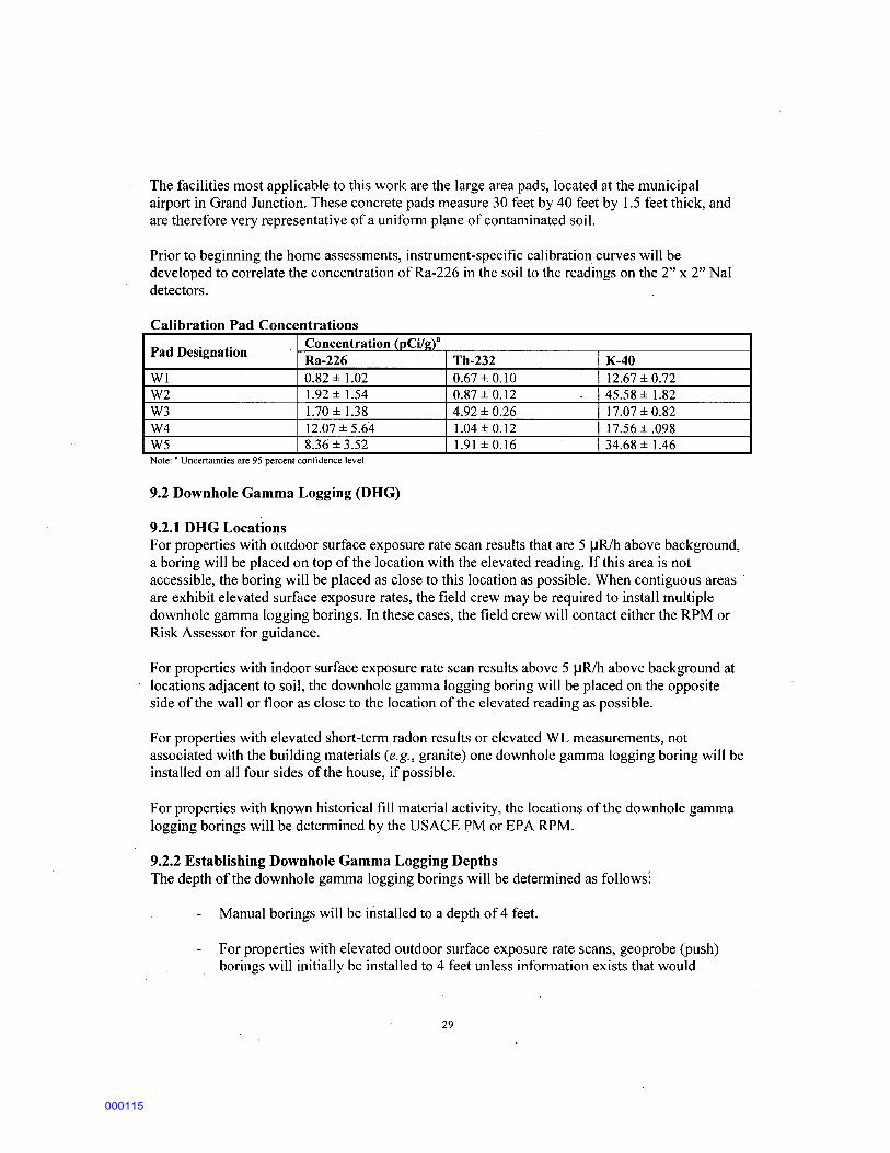
The facilities most applicable to this work are the large area pads, located at the municipal airport in Grand Junction. These concrete pads measure 30 feet by 40 feet by 1.5 feet thick, and are therefore very representative of a uniform plane of contaminated soil.
Prior to beginning the home assessments, instrument-specific calibration curves will be developed to correlate the concentration ofRa-226 in the soil to the readings on the 2" x 2" Nal detectors.
Calibration Pad Concentrations
Pad Designation Concentration (pCi/2)8
Ra-226 Th-232 K-40 W1 0.82 ± 1.02 0.67 ± 0.10 12.67 ± 0.72 W2 1.92 ± 1.54 0.87 ± 0.12 45.58 ± 1.82 W3 1.70 ± 1.38 4.92 ± 0.26 17.07 ± 0.82 W4 12.07 ± 5.64 1.04 ± 0.12 17.56 ± .098 W5 8.36 ± 3.52 1.91 ± 0.16 34.68 ± 1.46 . Note: Uncertamttes are 95 percent confidence level.
9.2 Downhole Gamma Logging (DHG)
9.2.1 DHG Locations For properties with outdoor surface exposure rate scan results that are 5 IJR/h above background, a boring will be placed on top of the location with the elevated reading. If this area is not accessible, the boring will be placed as close to this location as possible. When contiguous areas · are exhibit elevated surface exposure rates, the field crew may be required to install multiple downhole gamma logging borings. In these cases, the field crew will contact either the. RPM or Risk Assessor for guidance.
For properties with indoor surface exposure rate scan results above 5 IJR/h above background at locations adjacent to soil, the downhole gamma logging boring will be placed on the opposite side of the wall or floor as close to the location of the elevated reading as possible.
For properties with elevated short-term radon results or elevated WL measurements, not associated with the building materials (e.g., granite) one downhole gamma logging boring will be installed on all four sides of the house, if possible.
For properties with known historical fill material activity, the locations of the downhole gamma logging borings will be determined by the USACE PM or EPA RPM.
9.2.2 Establishing Downhole Gamma Logging Depths The depth of the downhole gamma logging borings will be determined as follows:
Manual borings will be installed to a depth of 4 feet.
For properties with elevated outdoor surface exposure rate scans, geoprobe (push) borings will initially be installed to 4 feet unless information exists that would
29
000115

indicate deeper contamination (e.g., contamination on adjacent or surrounding properties is deeper than four feet)
For properties with elevated indoor exposure rate scans, and where the short-term radon results are greater 4 pCi/L or the measured Working Level is greater than 0.02 WL, geoprobe borings will initially be installed to a depth of 8 feet.
Regardless of the initial depth, the depth of the boring will be extended if elevated count rates that are not associated with native material are found at the bottom of the boring or if readings are increasing significantly toward the bottom of the boring. Note that this will be a field decision since elevated readings can be found in conjunction with naturally occurring materials such as clay. If elevated readings are found in a clay layer, the PM will be -responsible for determining if the boring should be extended. Typically this decision will be made in consultation with the RPM
9.2.3 Downhole Gamma Logging Action Levels A count rate action level based on regional background will be established and used for a W' x 1" Nal detector at boreholes. If this level is exceeded, and there is no evidence that the geologically at that depth would give rise to elevated readings, a soil sample will be taken from the depth of the elevated readings.
A count rate action level based on regional background will be established and used with a 2" x 2" Nal detector at boreholes. If this level is exceeded, and there is no evidence that the geologically at that depth would give rise to elevated readings, a soil sample will be taken from the depth of the elevated readings.
30
000116

10.0 EPA ERGS Vehicle Scanning Prior to USACE Phase 2 survey efforts, EPA Region 6 will perform a surface gamma scan using the EPA's ERGS gamma scanning vehicle. The intent of this scanning is to evaluate the possibility that radioactive contamination originating from the evaporation ponds has been deposited on residential soil through the air or surface runoff. This scanning will consist of multiple straight line patterns that resemble stripes. Scans will utilize GPS technology to log the locations of the survey area and identify areas of elevated readings. Several of the stripes will originate at the evaporation ponds and will terminate in different residential areas located close to the site. The three residential areas are Pleasant-Valley Estates, Murray-Acres, and Broadview-Acres. A background area will be identified and gamma scanning using the ERGS will be determined for that area and used as a baseline for the site.
The ERGS vehicle will also be used in the center pivot and flooded irrigation areas, scanning in straight line patterns towards the residential areas. The proposed ERGS survey areas are diagrammed in the figure below.
234500 235000 235500 236000 236500 237000 237500 238000 238500 239000 239500 240000
Results of the ERGS survey may be used by the USACE or by radiological services contractor to . identify potential areas of concern for additional survey investigation and sample collection.
31
000117

11.0 References
1. AR 385-10, The Army Safety Program.
2. EM 200-1-3, Requirements for the Preparation of Sampling and Analysis Plans
3. ER and EM 385-1-80, 30 May 1997, Ionizing Radiation Protection; and Radiation Protection, USACE.
4. EM-385-1-1, 3 Sep 1996, Safety and Health Requirements Manual, USACE.
5. EPA QA/R-5- EPA Requirements for Quality Assurance Project Plans
6. Homestake Mining Company Mill Site Health Consultation, A TSDR, June 2009
7. Homestake Mining Company EPA Superfund Record ofDecision, September 1989
8. NRC 2000 NUREG-1575, Multi-Agency Radiation Survey and Site Investigation Manual (MARSSIM), August 2000.
9. Title 10, CFR, 1996 rev, Chapter I, Nuclear Regulatory Commission (USNRC).
10. Title 29, CFR, 1995 rev, Chapter I, Department of Labor.
11. NUREG/CR-5849, ORAU-92/C57, 1 June 1992, Manual for Conducting Radiological Surveys in Support of License Termination (DRAFT), USNRC.
12. NUREG 1507, ORAU, June 1998, Minimal Detectable Concentrations With Typical Radiation Survey Instruments for Various Contaminants and Field Conditions, USNRC.
13. DA PAM 385-24 Department of the Army Pamphlet 385-24, Safety, The Army Radiation Safety Program, Headquarters, Department of the Army, Washington, DC, 24 August 2007
32
000118

Appendix A- Project Documents
33
000119

Example Daily Quality Control Report Form
DAILY QUALITY CONTROL REPORT Date: Day:
Project: Report
No.: Wind:
Humidity:
Weather:
Project Manager:
Personnel On Site:·
Contractors On Site:
Visitors On Site:
Equipment On Site:
Work Performed:
Quality Control Activities:
Health And Safety Levels And Activities:
Problems Encountered/ Corrective Action Taken:
Other Comments:
34
000120
35
000121

PROJECT NAME
SURVEYOR NAME
SURVEY DIAGRAM
Sample Survey Form
36
r.Pr.'1 ~
000122

37
000123

!INSTRUMENT TYPE
CALIBRATION DATE
BACKGROUND COUNT RATE
SURVEY READINGS
REMARKS
SURVEYOR SIGNATURE
38
INSTRUMENT SERIAL NUMBER
CALIBRATION DUE
DATE
000124

Sample Survey Instrument QC Check Form
Daily BETA QC Checks 2360 S/N 145468
1400
1350 'V )K 'V
1300
1250 ~~ ~ ~ 1200
'V)K 1150
,,,
1100 1 2 3 4 5 6 7 8 9101112131415161718192021222324252627282930
Count Number
l--3s ---2s -Mean --+2s -+3s ::t:: Reading I
Daily BET A Checks in cpm Date Gross BKG NET GROSS BKG NET GROSS BKG NET
1 17Sep02 1549 240 1309 NO 1579 327 1252 2 18Sep02 1495 255 1240 NO 1427 261 1166 3 19Sep02 1450 266 1184 1612 285 1327 1547 308 1239 4 20Sep02 1612 302 1310 1523 282 1241 NU 5 0 0 0 6 0 0 0 7 0 0 0 8 0 0 0 9 0 0 0
10 0 0 0
39
000125

1400
QC Chart 2360 SIN 145468
BETA43-89
~ 1300~---------------------~~---~-----~~,~~-------------~----~---~--
8 ~-6-0- A 0/~ \ \ 6 I\ I\ I '~ ~ 1200 I v \ I " I \ I v --~-~-"'<f \I \I
~ 0 ~-~ ~ ~
1100+-~~~~-r~~~~~r-~~~-r~~~~~r-~~~-r~
1 2 3. 4 5 6 7 8 9 10 11 12 13 14 15 16 17 18 19 20 21 22 23 24 25 26 27 28 29 30
Count Number
-~-NET ---+3s ---+2s -Mean ----2s ----3s I
Model: 2360 ISN# 145468 PROBE 43-89 SN# 169229 Cal Due: Source: Tc-99 ISN# Activity: 14,100 dpm Cal Date:
Mean +2s -2s +3s: -3s Date: 1234 1305 to 1163 to 1341 to 1128 Efficiency: Chk.# Gross Net Chk.# Gross Net Chk.# Gross Net
1 1336 1175 11 1403 1242 21 1376 1215 2 1407 1246 12 1424 1263 22 1382 1221 3 1403 1242 13 1445 1284 23 1391 1230 4 1406 1245 14 1441 1280 24 1367 1206 5 1394 1233 15 1344 1183 25 1442 1281 6 1361 1200 16 1348 1187 26 1358 1197 7 1396 1235 17 1465 1304 27 1432 1271 8 1346 1185 18 1438 1277 28 1349 1188 9 1399 1238 19 1389 1228 29 1435 1274 10 1356 1195 20 1402 1241 30 1417 1256
161 cpm Mean: 1234 cpm 2sigma: 71 cpm 3sigma:
40
26Mar03 1Feb95 17Sep02
0.088 COMMENTS
106 cpm
000126
-~ CHAIN OF CUSTODY RECORD NAnONALAJR AND RADIA'DON ENVIRONMENTAL lABORATORY
PlojedN~ t ANALYSIS REQUESTED
Project Maoagcr of
Sampllna Temn.Mc:mbm c 0 N T A .I
N
Requc3tal ~ldkQ ' Notify Project Manaaer B
Dlue Upm ~Uccipl'l 0 Ya 0 No R s
s..plc Oeocripiaa Iloilo Timot MIIJR
I) Samp.Ur, Dolo:J'IImo l) boci..-..1 By. llolotTilllll
3) ltdi!lqttlsbed By: llee<I'I';Oilll 4).Rtcei¥edB}; DIMclrllllll
:S) Rel!a<tu<illood By: DatdT'Imo 6) Reechoed By: Doldl'ipJO
Sandce Diopoe<d Dr, lloilofl!IJoc Dla-.!Molbacl:
548 Sua .. Manb ·- ' ~'1,AL Ccintainer# lQ!$-Ml (~:m.34011 Fa (334) 270-:1454
fl~~~~Wl~~~~~li#~~q~~~fi:~:~l~::~~~~E~ Commenu:
CommeniS Lnb Sample lD
s...,p~c Sl!ippod vi:> llll<taoiC<Doiner 0 [] a D
l'o:ldl!x UPS H....t Otflor T~"'-·c
a...,dJ Sool """""'11 cY t:lN hac
CJoslcJ4)' 8<a11JWICI? OY ON or
l j ~-
~ ~ 'i
I j
I 1 1
i
j l ,.
i ! 1
000127

Landauer Radtrack a-track detector information
LANDAUER®
Radtrak® Long-Term Radon Monitoring
Radtrak is an alpha-track radon gas detector designed to monitor radon exposure for three months to one year to obtain a long-term average concentration over time. Landauer service includes the Radtrak detector, comprehensive analysis, and a confidential report of the findings. Radtrak can be packaged lor indoor or outdoor area mon~oring or personnel monitoring.
Landauer Is the leader and pioneer in radon gas detection and monitoring service. Since 1954, our scientists have been involved with the development of radiation monitoring services for nuclear research centers and laboratories, hospitals, medical and dental offices, univers~ies, and other industries where radiation might be present. This experience and technology have been incorporated into Landauer's highly accurate Radtrak radon detector using our exclusive Track:Etch" process. Radtrak radon detectors are used by the Environmental Protection Agency, the National Institutes of Health, the American Lung Association, and many other government and professional organizations.
·--Radlrak measures the average radon concentration at the location of the detector during the monitoring period. The alpha-track detector has, inside the plastic housing, a radiosensitive element that records alpha particle emissions {alpha tracks) from the natural radioactive decay of radon.
~ -~ ,,, . . ''' ,,, -
When the detector is returned to Landauer's laboratory, the alpha tracks are counted using computer-assisted Image analysis equipment. The number of alpha tracks along with the deployment time period provides the basis for calculating the average radon concentration. The report with the radon gas measurement, reported in picocuries per liter of air (pCill), is mailed within seven to ten days after receipt of detector.
Thoron Proof Filter Upon request, a detector can be fitted with a thoron proof filter that provides measurement of An 222 only.
Technical Specifications • The radiosensitive element is a CR-39 (allyl diglycol
carbonate) based, passive alpha-track detector. • The CR-39 Is enclosed in a plastic housing
composed of electrically conducting material with filtered openings to permit diffusion of radon gas only.
• Minimum level of detection Is 30 pCiA days i.e., 0.33 pCiA based on 90 days.
Detectors, before, during or after exposure, should
I not be in locations that exceed a temperature of I 160°F (70°C). , • Radtrak detectors are packaged in film-foil bags that I meet Military specification MIL-B-131, Class 1 to I prevent exposure prior to use. • • A metallic label is provided lor each detector to seal I lhe filtered openings following the exposure period to
I' minimize subsequent exposure to radon during the
return shipment to Landauer's laboratory. • Each detector is identified by a unique serial number
laser engraved on the CR-39, printed and bar coded ( on the outside of Radtrak, and the film-foil bag.
l
Indoor Use Monitoring Indoors requires placing the detector in an upright position on a flat surface, or~ may be hung from a joist or ceiling with the detector's hanger strip included with the shipment. The U.S. Environmental Protection Agency recommends the detector be placed in the lowest lived-in level of the home. It should be placed in a room that is used regularly but not a kitchen or bathroom. states or other organizations may have differing recommendations. Contact your state agency if you have a question regarding placement.
Outdoor Use For monitoring outdoors, the detector Is fastened to the bottom of a clear plastic cup. The cup is then installed Inside a protective canister that has been attached to a post or other location. The protective canisters are sold separately.
Personnel Monitoring The personnel monitor comes with a clip that easily attaches to the detector and securely fastens to clothing.
For more information on radon, refer to the U.S. Environmental Protection Agency's publication "A Citizen's Guide to Radon" at http://www.epa.govliaq/ radonlpubs/citgulde.html or contact your state department of health.
I Landauer, Inc. • 2 Science Road · Glenwood, ll 60425 800-528-8327 · www.landauerinc.com · 11)2005 by Landauer, Inc.
42
000128

Appendix B- Sampling SOPs
43
000129

Field Equipment Cleaning and Decontamination
Management of Investigation Derived Waste
Sediment Sampling
Soil Sampling
Surface Water Sampling
Wipe (Contaminated Surface) Sampling
Field Sampling and Measurement Procedures and Procedure Validation
Field Sampling Quality Control
Logbooks
44
000130