FIELD OVERSIGHT SUMMARY 2 - RD FIELD OVERSIGHT (PRC · PDF filebe consolidated to form the...
154
""1 /"VZjT"'! PRC Environmental Management. Inc ' ^ ^ 1 200 East Randolph Drive OOOOC" ; ) Suite 4700 Chicago. IL 60601 312-856-8700 Fax 312-938-0118 December 29, 1995 PRC Mr. John O'Grady Remedial Project Manager U.S. Environmental Protection Agency Region 5 77 West Jackson Boulevard Chicago, IL 60604 Subject: Field Oversight Summary No. 2; Remedial Design Field Oversight Woodstock Municipal Landfill, Woodstock, Illinois EPA Contract No. 68-W8-0084, Work Assignment No. 77-5DBP Dear Mr. O'Grady: On various days from June 28 through November 16, 1995, PRC Environmental Management, Inc. (PRC), conducted field oversight activities at the Woodstock Municipal Landfill (WML) site in Woodstock, Illinois. Field oversight activities included the following: • Observing the borrow area soil sampling at the Precision Quincy property in Woodstock, Illinois • Observing the installation of monitoring wells, an extraction well, and gas probes • Observing the drilling of bore holes to determine the thickness of the landfill cover and the lateral extent of waste • Observing the delineation of wetlands around the WML site • Observing the collection of groundwater and surface soil samples • Collecting groundwater split samples • Observing the borrow area soil sampling at the D.B. Hess property in Woodstock, Illinois • Observing the pump test During the oversight period, the following individuals represented PRC: Shin Ann, Korreen Ball, Mary Joyce Freibert, Ray Mastrolonardo, Carol Richardson, Kevin Schnoes, Jeff Swano, and Judy Wagner. A summary of PRC's oversight and sampling activities is presented in the enclosure. Appendix A of the enclosure contains photographs of oversight activities and Appendix B contains a copy of PRC's field notes. If you have any questions, please call me at (312) 856-8721. Sincerely, 'Manoj Mishr Site Manager Enclosure cc. Thomas Short, EPA Project Officer (letter onl^i) Marguerite Hendrixon, EPA Contracting Officer (letter only) Majid Chaudhry, PRC (letter only)
Transcript of FIELD OVERSIGHT SUMMARY 2 - RD FIELD OVERSIGHT (PRC · PDF filebe consolidated to form the...

""1 /"VZjT"'! PRC Environmental Management. Inc' ^ 1 200 East Randolph Drive
O O O O C " ;) Suite 4700Chicago. IL 60601312-856-8700Fax 312-938-0118
December 29, 1995 PRCMr. John O'GradyRemedial Project ManagerU.S. Environmental Protection AgencyRegion 577 West Jackson BoulevardChicago, IL 60604
Subject: Field Oversight Summary No. 2; Remedial Design Field OversightWoodstock Municipal Landfill, Woodstock, IllinoisEPA Contract No. 68-W8-0084, Work Assignment No. 77-5DBP
Dear Mr. O'Grady:
On various days from June 28 through November 16, 1995, PRC Environmental Management, Inc. (PRC),conducted field oversight activities at the Woodstock Municipal Landfill (WML) site in Woodstock, Illinois.Field oversight activities included the following:
• Observing the borrow area soil sampling at the Precision Quincy property in Woodstock,Illinois
• Observing the installation of monitoring wells, an extraction well, and gas probes• Observing the drilling of bore holes to determine the thickness of the landfill cover and the
lateral extent of waste• Observing the delineation of wetlands around the WML site• Observing the collection of groundwater and surface soil samples• Collecting groundwater split samples• Observing the borrow area soil sampling at the D.B. Hess property in Woodstock, Illinois• Observing the pump test
During the oversight period, the following individuals represented PRC: Shin Ann, Korreen Ball, MaryJoyce Freibert, Ray Mastrolonardo, Carol Richardson, Kevin Schnoes, Jeff Swano, and Judy Wagner. Asummary of PRC's oversight and sampling activities is presented in the enclosure. Appendix A of theenclosure contains photographs of oversight activities and Appendix B contains a copy of PRC's field notes.
If you have any questions, please call me at (312) 856-8721.
Sincerely,
'Manoj MishrSite Manager
Enclosure
cc. Thomas Short, EPA Project Officer (letter onl^i)Marguerite Hendrixon, EPA Contracting Officer (letter only)Majid Chaudhry, PRC (letter only)

ENCLOSURE
FIELD OVERSIGHT SUMMARY NO. 2REMEDIAL DESIGN FIELD OVERSIGHTWOODSTOCK MUNICIPAL LANDFILL
WOODSTOCK, ILLINOIS
(29 Pages)

FIELD OVERSIGHT SUMMARY NO. 2REMEDIAL DESIGN FIELD OVERSIGHTWOODSTOCK MUNICIPAL LANDFILL
WOODSTOCK, ILLINOIS
PRC Personnel: Shin AhnKorreen BallMary Joyce FreibertRay MastrolonardoCarol RichardsonKevin SchnoesJeff SwanoJudy Wagner
Reporting Period: June 28 through November 16, 1995
PRC Environmental Management, Inc. (PRC), received Work Assignment No. 77-5DBP from the U.S.Environmental Protection Agency (EPA) under Contract No. 68-W8-0084 to conduct remedial design
(RD) oversight activities at Woodstock Municipal Landfill (WML) in Woodstock, Illinois.
As part of this assignment, from June 28 to November 16, 1995, PRC conducted oversight activities
for various RD-related activities at the site. The RD activities are being performed by the potentially
responsible parties (PRP), the City of Woodstock and Allied Signal, Inc. The PRPs have contracted
Conestoga-Rovers & Associates (CRA) as consulting engineer for the RD activities.
In June and July, 1995, CRA conducted soil sampling activities at a potential off-site soil source locatedon the Precision Quincy property at 1625 North Lakeshore Drive in Woodstock, Illinois. The soil was
being investigated for suitability as general fill or capping material for the WML site.
The oversight activities that PRC conducted on various days from September 11 through October 24,
1995, consisted of observing CRA and the drillers, Boart Longyear (Boart), as they installedmonitoring wells, an extraction well, and gas probes. PRC also provided oversight as CRA drilled
E-l
borings to determine the thickness of the landfill cover and the lateral extent of waste. In addition,
PRC oversaw wetlands delineation and groundwater and soil sampling.
On November 7, 8, and 9, 1995, PRC provided oversight as CRA collected soil samples at a potential
off-site soil source located on the D.B. Hess property in Woodstock, Illinois. The soil at this site was
investigated for its suitability as general fill or capping material for the WML site. CRA estimated that
the borrow area was approximately 700 feet long and 600 feet wide, and that available soil in the
borrow area would equal about 100,000 cubic yards (yd3). CRA proposed dividing the 700- by 600-
foot area into 42 equal grid sections, each containing approximately 2,500 cubic yards of fill, andcollecting a sample from the center of each grid section. However, the borrow area shape was notrectangular and the entire area was divided into only 32 equal grid sections and two soil berms.
On November 10, 13, 14, 15, and 16, 1995, PRC oversaw the pump test of extraction well (EW)-l.
A summary of PRC's observations and activities at the WML site during oversight of borrow area soil
sampling and predesign field investigations is presented below. The photographs taken during the field
oversight are presented in Appendix A and a copy of PRC's field notes is included in Appendix B.Photograph numbers cited in this trip report do not correspond with the numbers indicated in the field
notes. Also, some photographs were omitted from this trip report to avoid redundancy and reduce thelength of the report.
Wednesday, June 28, 1995
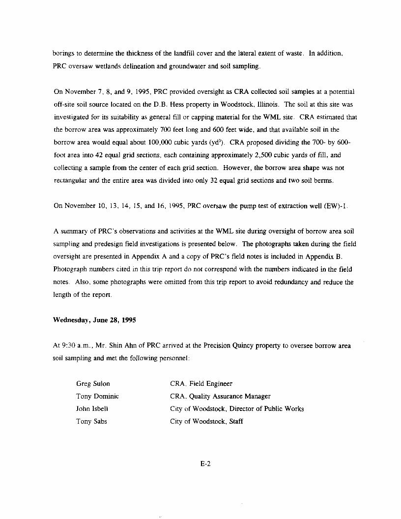
At 9:30 a.m., Mr. Shin Ann of PRC arrived at the Precision Quincy property to oversee borrow areasoil sampling and met the following personnel:
Greg Sulon CRA, Field Engineer
Tony Dominic CRA, Quality Assurance Manager
John Isbell City of Woodstock, Director of Public WorksTony Sabs City of Woodstock, Staff
E-2

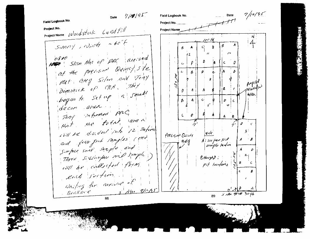
The area that CRA is investigating as a potential borrow source is located north of the existing structure
on the Precision Quincy property. CRA briefly surveyed and roughly estimated the borrow source areato be excavated. CRA informed PRC that the rectangular area to be excavated measured about 130 by
100 yards and, if excavated to a depth of 6 feet, would yield approximately 27,000 yd3 of fill material.CRA also stated that the source area would be divided into 11 sections that would be excavated andsampled, based on collecting one soil sample for every 2,500 yd3 of soil. PRC observed that the area
currently consists of open field mostly vegetated by tall grass (see Photograph No. 1).
After the backhoe operator arrived at the site, CRA directed the excavation of the first test pit andcollected one grab sample from the soil pile generated from the test pit. The headspace of the samplebottle was monitored for volatile organic compounds (VOC) with a photoionization detector (PID). No
reading above background was obtained. CRA collected additional grab samples to be analyzed formetals, polychlorinated biphenyls (PCB), and pesticides (see Photograph No. 2). The backhoe
continued to excavate the next test pit as CRA directed.
PRC questioned CRA regarding its sampling practices. According to the approved work plan, each of
the 11 sections included in the source area should be divided into four quadrants and a representative
grab sample should be collected from the center of each quadrant. The four grab samples would then
be consolidated to form the "field source" composite sample for that section. However, CRA did not
divide the source area into 11 sections each with four quadrants and it did not composite the four grab
samples from each of the quadrants It was also unclear if the "source area" refers to 2,500 or27,000 yd3 of material. To resolve these issues, PRC and CRA agreed to contact their respectiveproject managers.
PRC and CRA drove off site to contact Mr. Manoj Mishra of PRC and Mr. Steven Wanner of CRA todiscuss these issues. After discussions between Mr. Mishra and Mr. Wanner, it was agreed to delaycollecting soil samples for chemical analysis until the extent of "source area" was clearly defined. Itwas further agreed that test pits would be excavated and samples collected only for analysis of selectedgeotechnical parameters (for example, grain size distribution).
Later in the afternoon, CRA collected samples for analysis of geotechnical parameters only. Upon
visual observation, the soils appeared to be free of contamination and no discoloration of soils was
E-3
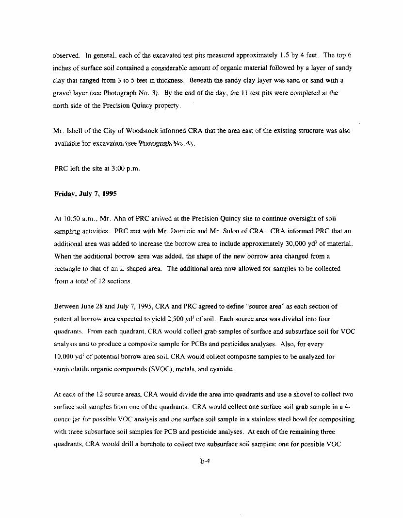
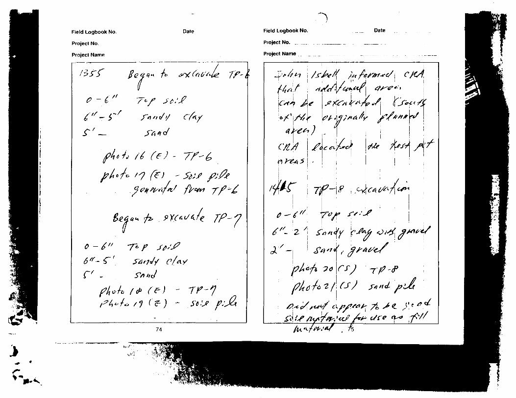
observed. In general, each of the excavated test pits measured approximately 1 .5 by 4 feet. The top 6inches of surface soil contained a considerable amount of organic material followed by a layer of sandyclay that ranged from 3 to 5 feet in thickness. Beneath the sandy clay layer was sand or sand with agravel layer (see Photograph No. 3). By the end of the day, the 1 1 test pits were completed at thenorth side of the Precision Quincy property.
Mr. Isbell of the City of Woodstock informed CRA that the area east of the existing structure was alsoavailable "tor excavatrun '$&t "ftfttefgraffei ¥«. . 4>, .
PRC left the site at 3:00 p.m.
Friday, July 7, 1995
At 10:50 a.m., Mr. Ann of PRC arrived at the Precision Quincy site to continue oversight of soilsampling activities. PRC met with Mr. Dominic and Mr. Sulon of CRA. CRA informed PRC that anadditional area was added to increase the borrow area to include approximately 30,000 yd3 of material.When the additional borrow area was added, the shape of the new borrow area changed from arectangle to that of an L-shaped area. The additional area now allowed for samples to be collectedfrom a total of 12 sections.
Between June 28 and July 7, 1995, CRA and PRC agreed to define "source area" as each section of
potential borrow area expected to yield 2,500 yd3 of soil. Each source area was divided into four
quadrants. From each quadrant, CRA would collect grab samples of surface and subsurface soil for VOC
analysis and to produce a composite sample for PCBs and pesticides analyses. Also, for every
10.000 yd3 of potential borrow area soil, CRA would collect composite samples to be analyzed for
semivolatile organic compounds (SVOC), metals, and cyanide.
At each of the 12 source areas, CRA would divide the area into quadrants and use a shovel to collect two
surface soil samples from one of the quadrants. CRA would collect one surface soil grab sample in a 4-
ounce jar for possible VOC analysis and one surface soil sample in a stainless steel bowl for compositing
with three subsurface soil samples for PCB and pesticide analyses. At each of the remaining three
quadrants, CRA would drill a borehole to collect two subsurface soil samples: one for possible VOC
analysis and one for compositing for PCB and pesticide analyses. After completing sampling at all four
quadrants, CRA would screen the headspace of the VOC samples with a PID, select the VOC sample
with the highest PID reading for off-site VOC analysis, and discard the other three VOC samples. For
the composite samples, CRA would mix the soil in the stainless steel bowl and place portions into 8-
ounce containers for PCB and pesticide analyses (see Photograph No. 5). In addition, for every 10,000
yd3 of borrow soil, CRA would place portions of the composited soil into 8-ounce containers for SVOC,
metals, and cyanide analyses.
At the first borrow source area, CRA divided the area into quadrants and collected the two surface soil
samples. CRA then proceeded to one of the remaining quadrants to collect subsurface soil samples. At
the first borehole location, CRA drove a split-spoon sampler about 2 feet below ground surface (bgs)
using a hammer (see Photograph No. 6). A sandy clay layer slowed the hammering and made it
difficult to pull the sampler out of the borehole. As a result, CRA decided to use a power auger insteador a split-spoon sampler.
CRA rented a power auger, returned to the site, and cleaned the auger before using it (see PhotographNo 7). CRA informed PRC that it planned to drill nine boreholes in the first three of the 12 sourceareas with a 3-foot-long auger. CRA said it would not decontaminate the auger between borings in
order to expedite sampling. After completing the nine 3-foot-deep boreholes, CRA said it would
extend the auger by one foot and each borehole then would be redrilled to a depth of 4 feet bgs. The
auger would then be decontaminated before redrilling each subsequent borehole.
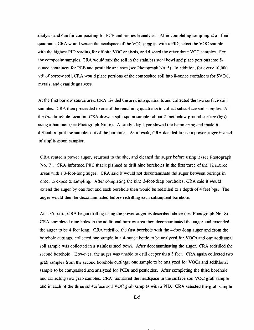
At 1:35 p.m., CRA began drilling using the power auger as described above (see Photograph No. 8).CRA completed nine holes in the additional borrow area then decontaminated the auger and extendedthe auger to be 4 feet long. CRA redrilled the first borehole with the 4-foot-long auger and from the
borehole cuttings, collected one sample in a 4-ounce bottle to be analyzed for VOCs and one additional
soil sample was collected in a stainless steel bowl. After decontaminating the auger, CRA redrilled the
second borehole. However, the auger was unable to drill deeper than 3 feet. CRA again collected two
grab samples from the second borehole cuttings: one sample to be analyzed for VOCs and additionalsample to be composited and analyzed for PCBs and pesticides. After completing the third boreholeand collecting two grab samples, CRA monitored the headspace in the surface soil VOC grab sampleand in each of the three subsurface soil VOC grab samples with a PID. CRA selected the grab sample
E-5

with the most elevated headspace reading (10.1 parts per million [ppm]) to be analyzed for VOCs. Theremaining three samples for VOC analysis were discarded. CRA then composited the four grab
samples (one surface soil and three subsurface soil) in the stainless steel bowl and filled four 8-ounce
bottles with the composited sample. This sample was collected for PCBs, pesticides, SVOCs, metals,and cyanide analyses.
Because CRA completed sample collection for only one of the source areas, it decided to use a backhoe
instead of a power auger on Monday to facilitate the sampling activities. CRA backfilled all boreholeswith soil cuttings.
PRC left the site at 4:00 p.m.
Monday, July 10, 1995
Mr. Shin Ann of PRC arrived at the Precision Quincy site at 8:00 a.m. At 10:20 a.m., a backhoe
provided by the City of Woodstock arrived at the site and began to excavate test pits in Source Area 2,as CRA directed. The backhoe bucket was decontaminated after three test pits in Source Area 2 wereexcavated. CRA cleaned the bucket with an Alconox® solution and a brush and then rinsed the bucketwith distilled water (see Photograph No. 9).
CRA collected samples from Source Area 2 using the same size containers and compositing proceduresas those described previously for Source Area 1. CRA informed PRC that soil samples collected from
Source Areas 5 and 9 would be analyzed for SVOCs and cyanide in addition to the previouslymentioned analytes.
The backhoe continued to excavate test pits in the remaining source areas and CRA continued to collectsoil samples throughout the morning.
At 2:00 p.m., the backhoe was used to complete excavation of all test pits through Source Area 12.
CRA also completed collecting soil samples through Source Area 12. The backhoe operator thenbackfilled the test pits where samples had been collected. After returning to the decontamination area,CRA calibrated the PID and conducted headspace readings for samples to be analyzed for VOCs (see
E-6

Photograph No. 10). CRA selected the grab sample with the most elevated reading from each source
area. The remaining three grab samples from each source area were discarded.
After completing the headspace reading, CRA packed the sample coolers. PRC left the site at 4:00
p.m.
Monday, September 11, 1995
At 9:10 a.m., Mr. Ray Mastrolonardo and Ms. Mary Joyce Freibert of PRC arrived at the WML site
and met Mr. Wanner and Mr. Walt J. Pochron, field manager, of CRA. PRC discussed the work and
field oversight schedule with CRA personnel. CRA also held a health and safety briefing at the site.During the day, PRC accompanied CRA personnel as they surveyed and marked with wooden stakes,
the locations where the new monitoring wells and extraction well would be placed. CRA met with thegas, electric, water, and telephone companies to delineate areas where drilling could not be conducted.At 11:50 a.m., Boart arrived at the WML site. Boart repaired the decontamination pad by replacing
the plastic cover and installing a new wooden perimeter. Boart also repaired monitoring well (MW)-6S
by connecting a 3-foot-long poly vinyl chloride (PVC) pipe to the existing PVC well. Boart also placed
4-inch-diameter steel risers around MW-6S and MW-6D.
PRC left the site at 4:30 p.m.
Tuesday, September 12, 1995
At 7:30 a.m., Ms. Freibert of PRC arrived at the WML site. CRA held a health and safety briefing
with PRC and Boart personnel. For the day, CRA planned to develop MW-6S and MW-6D and to
drill a monitoring well. CRA and Boart personnel wore Level D personal protective equipment (PPE)
while developing MW-6S. Boart had to flush MW-6S with about 30 gallons of water to remove soil
and paniculate that was blocking the well (see Photograph No. 11). After flushing MW-6S andremoving the blockage, Boart began purging the well. Purged water was containerized in a 55-gallon
steel drum. About 5 gallons of water was purged; this exceeded the amount that needed to be purged,and the pH, conductivity, temperature, turbulence, and appearance of the water were stable.
E-7

Therefore, MW-6S was considered to be developed. After completing the development of MW-6S,
Boart decontaminated the pump with Alconox* and deionized water.
Boart then tried to purge MW-6D; however, Boart encountered a blockage in the well when placing thehose to the pump into the well. CRA decided to excavate soil surrounding MW-6D to determine the
location of the bend in the well (see Photograph No. 12). Boart located and removed the bent portion
of pipe. Boart tried to replace the removed portion of pipe with a 5-foot length of PVC pipe; however,
the PVC pipe could not be connected to the existing well. Therefore, MW-6D was abandoned and will
have to be replaced (see Photograph No. 13). Boart placed all soil cuttings that resulted from thedigging at MW-6D into 55-gallon steel drums.
After lunch, CRA and Boart drilled a borehole for MW-14 with a hollow-stem auger (see PhotographNo. 14). Boart decontaminated the stainless steel risers for MW-14. CRA collected soil samples for
archiving in 8-ounce glass containers at every 2-foot-depth interval for each borehole. During drilling
activities, soil cuttings were placed in 55-gallon steel drums at each borehole location. Boart
encountered a 1-foot-thick sand layer at 21 feet bgs and continued to drill. Boart drilled to 32 feet bgs
but did not encounter another sand layer while installing MW-14. Mr. Pochron of CRA decided to
telephone Mr. Wanner of CRA to ask his opinion about the borehole. CRA decided to drill to 40 feet
bgs and encountered a sand layer from 32 to 36 feet bgs. CRA screened MW-14 from 28.5 to 38.5
feet bgs. PRC's observations indicated that MW-14 was installed in accordance with the approved
sampling analysis plan (SAP). Boart will grout and cement MW-14 tomorrow.
PRC left the site at 7:10 p.m.
Wednesday, September 13, 1995
At 8:30 a.m., Ms. Freibert of PRC arrived at the WML site. Boart personnel grouted and cemented
MW-14 and decontaminated augers and equipment by scrubbing with Alconox® and water solution. As
Boart was using the drill rig to drive to MW-12, the drill rig became stuck in the soil. After repeated
attempts, Boart could not pull the drill rig out of the soil. Therefore, CRA telephoned personnel fromthe City of Woodstock for assistance in removing the drill rig. The city personnel arrived on site and
surveyed the situation with CRA and Boart. The city personnel could not assist in removing the rig
E-8

today, but would return tomorrow. PRC accompanied CRA and Boart personnel as they surveyed the
locations for MW-12, MW-13, and the extraction well. After surveying the areas, Boart personnelbegan to unload the supply truck.
PRC left the site at 5:00 p.m.
Thursday, September 14, 1995
At 8:30 a.m., Ms. Freibert of PRC arrived at the WML site. CRA hired Dahm Trucking to pull the
drill rig out using a front-end loader. After the drill rig was freed, the front-end loader wasdecontaminated with Alconox® and water before leaving the WML site. Rinse water was contained inthe decontamination area and then pumped to an on-site holding tank. Boart personnel moved the drillrig to the location of MW-12 and drilled the borehole (see Photograph No. 15). Boart drilled to about
38 feet bgs but, as before, it did not encounter a sand layer while installing MW-12. Mr. Pochron ofCRA telephoned Mr. Wanner of CRA to ask his opinion about the borehole. CRA decided to abandonthe borehole and directed Boart to remove the augers (see Photograph No. 16). Boart took the augersand rods to the decontamination area and brought the bentonite powder and mixing trough back to theborehole. After Boart finished plugging the borehole, it began moving the drill rig to EW-1. The drillrig once again became stuck in a gray muddy material near the wetland area, but Boart was able toremove the drill rig. CRA and Boart resurveyed the locations of the MWs and EW-1, and CRA
decided to place MW-13 in a more stable area. Boart then moved the drill rig to the new location
where MW-13 would be placed. CRA and Boart personnel decided to drill MW-13 on the followingday. Boart personnel decontaminated the augers and equipment (see Photograph No. 17).
PRC left the site at 6:10 p.m.
Friday, September 15, 1995
At 8:00 a.m., Ms. Freibert of PRC arrived at the WML site. Boart personnel drilled the borehole at
the repositioned location of MW-13 and encountered a sand and gravel layer at 16 to 24 feet bgs.Boart then decontaminated the stainless steel risers for MW-13. MW-13 was screened from 14 to 24
E-9

feet bgs. MW-13 was installed in accordance with the SAP. Boart personnel then waited for morethan 1 hour to pass before grouting and cementing MW-13.
PRC left the site at 1:45 p.m.
Monday, September 18, 1995
At 11:00 a.m., Mr. Mastrolonardo of PRC arrived at the WML site. PRC discussed the proposedwork schedule with CRA personnel. CRA and Boart personnel spent the afternoon attempting to set upthe drill rig at EW-1 for drilling the pilot boring. Because the ground was soft along the southernportion of the landfill, the rig became stuck several times and maneuvering the rig was difficult. At
5:30 p.m., Boart finally positioned the rig at EW-1 and set up for drilling that will begin tomorrow.
PRC left the site at 6:00 p.m.
Tuesday, September 19, 1995
At 7:45 a.m., Mr. Mastrolonardo of PRC arrived at the WML site and met CRA and Boart personnelat EW-1. The pilot boring at EW-1 was drilled to a depth of 26 feet bgs (see Photograph No. 18).
Sand, measuring 1-foot thick, was detected at about 19 feet bgs. Boart grouted the EW-1 boring afterdrilling was complete. CRA and Boart spent the afternoon drilling waste delineation borings at soil
boring (SB) locations SB-114, SB-115, and SB-116. Whitish-gray sludge was detected at locations SB-
114 arid SB-115 at about 3 to 5 feet bgs (see Photograph No. 19). Traces of the whitish-gray sludgewere detected at location SB-116 at about 5 to 10 feet bgs.
PRC left the site at 5:15 p.m.
Wednesday, September 20, 1995
At 8:30 a.m., Ms. Judy Wagner of PRC arrived at the WML site and met with CRA and Boart
personnel. PRC was given a health and safety briefing. During the day, PRC observed the drilling ofsoil borings at locations SB-117 through SB-127. Refuse was detected in SB-119 at 5 feet bgs, in SB-
E-10

126 at 2 to 7 feet bgs, and in SB-127 at 2 to 6 feet bgs. All other soil borings were drilled to a depth of
10 feet bgs but no refuse was detected.
From 1:10 p.m. to 2:15 p.m., PRC observed CRA using an electromagnetic detector to delineate thelateral extent of waste along the southwest portion of the landfill. CRA staked the areas where wastewas detected; these stakes represented the boundary of the landfill waste.
PRC left the site at 5:00 p.m.
Thursday, September 21, 1995
At 7:45 a.m. Mr. Mastrolonardo of PRC arrived at the WML site and met with CRA and Boart. Boart
had two drilling crews on site; both were drilling waste delineation borings. One drilling crew drilled
delineation borings SB-128 through SB-134 and the other crew drilled delineation borings SB-70through SB-77. CRA also conducted bail down tests at MW-4D and MW-8 to obtain preliminary'
aquifer characteristics. The bail down tests were conducted by using air pressure to lower the water
level in the wells and to monitor recovery by using a data logger and pressure transducer.
PRC left the site at 5:00 p.m.
Friday, September 22, 1995
At 8:00 a.m., Ms. Wagner of PRC arrived at the WML site. For the day, CRA planned to install gas
probes in the northeast corner of the landfill and collect split-spoon samples of the soil boring atmonitoring well (SBMW)-8. PRC observed the soil boring at SBMW-8. A sand lens was detectedfrom 13 to 17.5 feet bgs. Boart advanced the soil boring to 22 feet bgs and detected silt both aboveand below the sand. Two soil samples were collected from the boring to be analyzed for grain size.Only one-half of a day of drilling and gas probe installation was scheduled.
PRC left the site at 12:00 noon.
E-ll

Monday, September 25, 1995
At 10:00 a.m., Ms. Wagner of PRC arrived at the WML site and met with Mr. Pochron of CRA who
stated that the drillers needed to complete decontamination of equipment before drilling could begin.At noon, CRA marked the locations on Davis Road where Boart would drill the soil borings. SB-77
through SB-83 were drilled at the marked locations (see Photograph No. 20). Each soil boring wasadvanced to 10 feet bgs and no waste was detected in any of the soil borings. Boart replaced most of
the soil cuttings in the boreholes and patched the asphalt pavement. Excess soil cuttings were placed ina 55-gallon drum that was moved to the on-site concrete storage pad.
PRC left the site at 4:30 p.m.
Tuesday, September 26, 1995
At 7:30 a.m., Mr. Mastrolonardo of PRC arrived at the WML site and met CRA and Boart personnel.
Two waste delineation borings were drilled, one each at locations SB-136 and SB-137. Gas probeswere then installed at gas probe (GP) locations GP-5, GP-6, and GP-7 (see Photograph No. 21). Boart
ran short of the sand needed to construct filter packs around the gas probes; therefore, drilling progress
was limited today. Boart spent the remainder of the afternoon decontaminating equipment; drilling will
resume tomorrow.
PRC left the site at 4:30 p.m.
Wednesday, September 27, 1995
At 7:45 a.m., Mr. Mastrolonardo of PRC arrived at the WML site. CRA and Boart personnel installedMW-12 next to the previously drilled pilot boring MW-12; therefore, no samples were collected duringdrilling. MW-12 was screened from 16.4 to 21.4 feet bgs to correspond with the depth of the sand
layer encountered in the pilot boring. The well was completed following CRA's proposed well
construction procedures. This included a sand pack followed by fine sand then a bentonite seal that
was placed above the fine sand. The bentonite was hydrated for about 2 hours before the grout was
E-12

placed to just below ground surface. In the afternoon, Boart installed piezometer (PZ)-l about 70 feeteast of MW-8 and installed gas probe GP-4.
PRC left the site at 5:15 p.m.
Thursday, September 28, 1995
At 8:20 a.m., Mr. Ann of PRC arrived at the WML site. For the day, CRA planned to install gas
probes and piezometers. Boart had installed GP-8 earlier in the morning. CRA and Boart drilled a
boring to 10 feet bgs at grid location 58 and installed GP-9 with a hollow-stem auger. CRA and Boartslotted a 1-inch-diameter PVC pipe and installed it. The boring was screened from 2.5 to 6 feet bgs tocorrespond with the depths at which the waste was encountered in the boring. CRA and Boart then
moved to grid location 56 to install GP-10. Boart drilled to 10 feet bgs. The depth of the waste was2.5 to 7.0 feet bgs. The PVC pipe was slotted from 2.5 to 7 feet bgs. The drillers then filled theboreholes with pea gravel up to 2 feet bgs and then topped the gravel with bentonite pellets. CRA
stated that bentonite would be hydrated to the surface and that no cement grout would be placedbecause the boring was not deep enough for it to be placed.
Boart drilled a boring for PZ-2 at a location about 50 feet west of MW-6. PRC observed that initialcuttings included black peat and gray silty-clay material. A sand layer was present from 17 to 20 feet
bgs. CRA collected soil samples at every 2-foot depth, using a split-spoon sampler. Drilling ended at
23 feet bgs. PZ-2 was screened from 17 to 22 feet bgs. PZ-2 was installed in accordance with CRA's
proposed well construction procedures. The bentonite was hydrated for about 1 hour before the cement
grout was placed to just below the ground surface.
PRC left the site at 4:00 p.m.
Friday, September 29, 1995
At 7:30 a.m., Mr. Mastrolonardo of PRC arrived at the WML site. CRA and Boart personnel installed
piezometer PZ-3. This piezometer was screened from 17 to 22 feet bgs. After PZ-3 was installed,
E-13

CRA and Boart moved to MW-6D to abandon the damaged well. MW-6D was abandoned by pressure
grouting the well from the bottom up by using a tremie pipe.
PRC left the site at 12:30 p.m.
Monday, October 2, 1995
At 9:30 a.m., Ms. Wagner of PRC arrived at the WML site. Boart rented a welding unit and jackedup the drill rig before beginning work for the day (see Photograph No. 22). At 3:30 p.m., installationof EW-1 began. Boart drilled a pilot hole with a 4-3/8-inch auger (see Photograph No. 23) beforedrilling with the 10-3/8-inch augers. Boart installed a 30-slot well screen with a 6-inch inside diameter
into EW-1; the well was screened from 13 to 18 feet bgs. The boring was drilled to a depth of 19 feetand the well was advanced to 18 feet. Red Flint Filter Sands and Gravel brand 30-slot sand was usedas a gravel pack around the well casing to a depth of 11 feet bgs with a 1-foot thickness of sand beneaththe well. Fine sand was then backfilled from 11 feet bgs to 9.8 feet bgs and bentonite was backfilledfrom 9.8 feet bgs to 6.8 feet bgs.
Shortly after 9:30 a.m., Ms. Carol Richardson of PRC arrived at the WML site and met Mr. Pochron
of CRA. PRC discussed the field oversight activities regarding wetlands delineation with CRApersonnel and waited for Christopher B. Burke Engineering, Ltd. (Burke), to arrive on site. CRA alsoheld a health and safety briefing for the site. At 11:25, Burke personnel Jedd Anderson and TomMcArdle arrived at the WML site. At 11:40, PRC and Burke personnel walked along the southeasternside of the landfill. An extensive wetland area was found outside of the east side of the WML.Wetlands species observed in this area included the common cattail (Typha angustifolia), reed canarygrass (Phalaris arundinacea), bulrush (Scirpus spp.), the sandbar willow (Salix exigula), and thecommon reed (Phragmites australis). An upland area separated much of this wetlands area from thelandfill. Burke personnel flagged the wetlands boundary.
Burke personnel observed part of the northeastern end of the landfill where several areas contained the
wetlands species, the sandbar willow and brome (bromus spp.). This area was discussed as beingproblematic, because although the vegetation was indicative of a wetlands area, the soils were
E-14

composed of fill material, and the topography was very uneven. Topographic relief and predominanceof wetlands vegetation were used to determine the wetlands boundary in this area. Burke personnelcontinued along the northern edge of the landfill until 1:15 p.m., when they had to depart the site.
PRC left the site at 7:15 p.m.
Tuesday, October 3, 1995
At 7:45 a.m., Mr. Mastrolonardo of PRC arrived at the WML site. CRA and Boart personnel were
placing grout around EW-1, which had been installed during the previous day. After placing grout at
EW-1, CRA and Boart developed wells MW-14 and MW-12 and piezometers PZ-1, PZ-2, and PZ-3.
Development procedures included measuring well depths and water levels, then surging and pumping
each well. Next, pH, temperature, and conductivity were measured three consecutive times untilsuccessive readings were within 10 percent of each other. Although turbidity is also normally
measured, it was not measured this day because the turbidity meter was not working properly. MW-14
was purged dry after about 9 gallons of water was removed. Boart and CRA agreed to finish
developing MW-14 the next day. About 65 gallons of water was purged from MW-12 and about 76,
65, and 70 gallons of water was purged from PZ-1, PZ-2, and PZ-3, respectively.
At 9:30 a.m., Ms. Richardson of PRC arrived at the WML site. Burke personnel arrived on site at
9:45 a.m. and PRC and Boart reviewed the previous day's work. After the short meeting, Burke wentto the northern end of the landfill to continue the wetlands delineation. The north end of the WML is
bounded by a frontage road, to the north of which are two open water areas surrounded by common
reed, cattails, soft-stemmed bulrush (Scirpus validus), and rush (Juncus spp.). Flags were placed along
the edge of these wetlands areas. Burke then proceeded to the northwest area of the landfill, where
they visually observed very dark organic soils. Vegetation included quaking aspen (Populus
tremuloides), reed canary grass, and raspberry (Rubus spp.). A data point was taken in the transition
area between the wetlands and the upland. Heading southward into a field area, tussock sedge (Carexstricta) was also observed. A soil pit dug in this area indicated rich dark organic soil, with a little
gleying (indicative of hydric soils) in a sandy horizon, down about 20 inches.
E-15
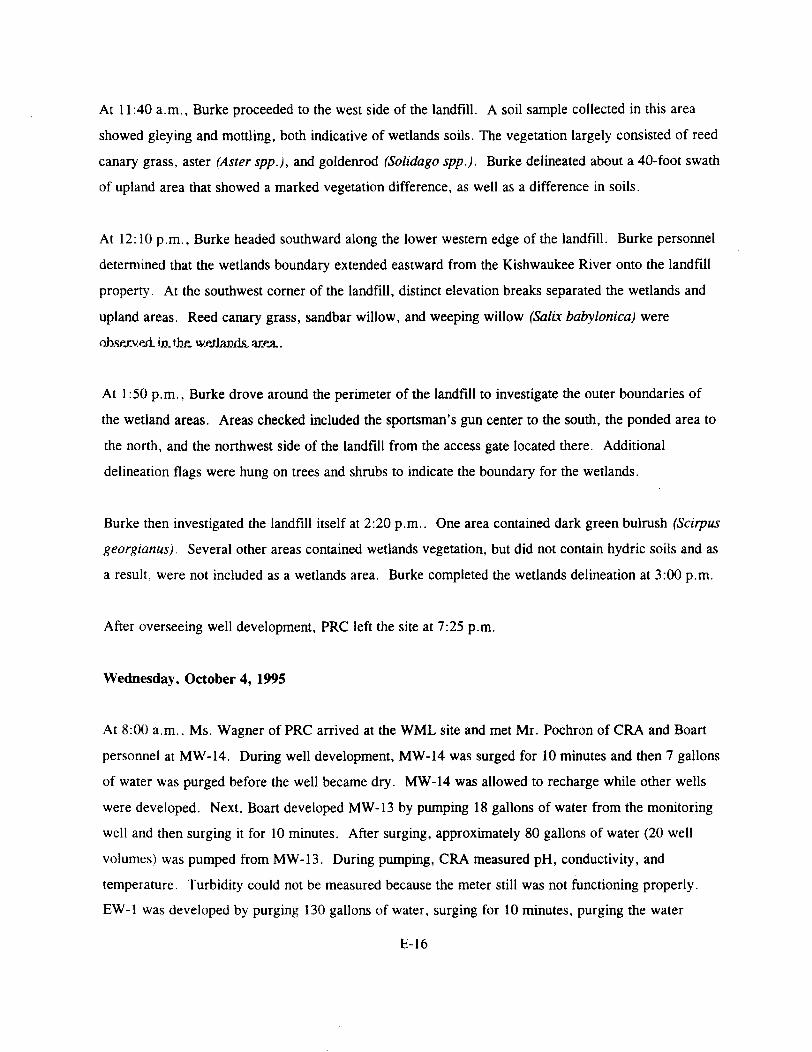
At 11:40 a.m., Burke proceeded to the west side of the landfill. A soil sample collected in this areashowed gleying and mottling, both indicative of wetlands soils. The vegetation largely consisted of reedcanary grass, aster (Aster spp.), and goldenrod (Solidago spp.). Burke delineated about a 40-foot swath
of upland area that showed a marked vegetation difference, as well as a difference in soils.
At 12: 10 p.m., Burke headed southward along the lower western edge of the landfill. Burke personneldetermined that the wetlands boundary extended eastward from the Kishwaukee River onto the landfillproperty. At the southwest corner of the landfill, distinct elevation breaks separated the wetlands and
upland areas. Reed canary grass, sandbar willow, and weeping willow (Salix babylonica) were
At 1:50 p.m., Burke drove around the perimeter of the landfill to investigate the outer boundaries of
the wetland areas. Areas checked included the sportsman's gun center to the south, the ponded area tothe north, and the northwest side of the landfill from the access gate located there. Additionaldelineation flags were hung on trees and shrubs to indicate the boundary for the wetlands.
Burke then investigated the landfill itself at 2:20 p.m.. One area contained dark green bulrush (Scirpus
georgianus). Several other areas contained wetlands vegetation, but did not contain hydric soils and asa result, were not included as a wetlands area. Burke completed the wetlands delineation at 3:00 p.m.
After overseeing well development, PRC left the site at 7:25 p.m.
Wednesday, October 4, 1995
At 8:00 a.m., Ms. Wagner of PRC arrived at the WML site and met Mr. Pochron of CRA and Boart
personnel at MW-14. During well development, MW-14 was surged for 10 minutes and then 7 gallons
of water was purged before the well became dry. MW-14 was allowed to recharge while other wellswere developed. Next, Boart developed MW-13 by pumping 18 gallons of water from the monitoringwell and then surging it for 10 minutes. After surging, approximately 80 gallons of water (20 wellvolumes) was pumped from MW-13. During pumping, CRA measured pH, conductivity, and
temperature. Turbidity could not be measured because the meter still was not functioning properly.
EW-1 was developed by purging 130 gallons of water, surging for 10 minutes, purging the water
E-16

again, surging for another 10 minutes, and then purging about 500 gallons of water (26 well volumes)while measuring the same three field parameters listed above. After development of EW-1, CRA and
Boart personnel returned to MW-14 and pumped out 6 gallons of water before the well again becamedry.
PRC left the site at 4:30 p.m.
Monday, October 16, 1995
At 9:00 a.m., Ms. Wagner of PRC arrived at the WML site and met with Mr. Pochron, Ms. Pat Klick,geologist, and Mr. Doug Soutter, geologist, all of CRA. CRA placed tubing to be used with the WellWizard pump in each monitoring well except at MW-6 because it had only 1.5 feet of water in it. CRAalso measured the water level of the extraction well, piezometers, and monitoring wells. Total depthmeasurements were made on the monitoring wells where samples were to be collected. PRC observedCRA as personnel took staff gauge measurements.
PRC left the site at 5:45 p.m.
Tuesday, October 17, 1995
At 7:45 a.m., Mr. Mastrolonardo and Mr. Ann of PRC arrived at the WML site. CRA personneldivided into two teams, one to conduct groundwater sampling and one to conduct soil and sedimentsampling. Mr. Mastrolonardo conducted oversight of groundwater sampling activities while Mr. Annconducted oversight of soil and sediment sampling activities.
The CRA groundwater sampling team prepared to collect samples from MW-1D first. Samplingequipment was decontaminated prior to purging the well. MW-1D was purged with a bladder pump.
The pH, temperature, and conductivity were stable before five well volumes were purged. Turbiditybecame stable after five volumes were purged. Samples collected from MW-1D were analyzed for allparameters listed in the approved SAP. CRA personnel left dedicated pump tubing inside MW-1Dafter the samples were collected. The bladder pump was decontaminated by pumping an Alconox® anddistilled water solution through the pump then rinsing it with clean water. CRA brought the purge and
E-17

decontamination water back to the drum storage area near the support zone. CRA purged MW-1S and
collected samples following the same procedures described above (see Photograph No. 24). CRA alsocollected samples from MW-7 following the same procedures with the exception that the well was
purged and a sample was collected using a peristaltic pump. The field change was made because MW-7 had a bend in it and the bladder pump could not be advanced beyond the obstruction. CRA personnel
spent the rest of the day labeling and packing samples.
Mr. Pochron of CRA's soil and sediment sampling team collected background soil samples startingwith location S-l. S-l is located about 300 feet east of the eastern landfill boundary. The surface soil
sample was collected from the upper 0 to 6 inches of topsoil using a trowel. The subsurface soilsample was collected from the 1 to 1.5-foot interval using a hand auger (see Photograph No. 25). Thesample was homogenized using a stainless steel spoon and bowl prior to being put into the propersample containers to be analyzed for target analyte list (TAL) metals and polynuclear aromatic
hydrocarbons (PAH). CRA personnel marked the sampling location with a wooden stake so thelocation could be surveyed later.
CRA decontaminated sampling equipment using Alconox® and distilled water after each soil sample
was collected. CRA moved to sampling location S-2 that is near the pond located behind the Farm andFleet building. CRA collected surface and subsurface soil samples at S-2 (see Photograph No. 26). In
the afternoon, CRA moved to sampling location S-3, which is located approximately 200 feet north ofDavis Road and 200 feet west of the Dorr Township building. However, junk cars, auto parts, and
tires were scattered about this area. Therefore, CRA moved to a location approximately 100 feet west
of the northwest corner of the Dorr Township building. CRA then collected surface and subsurfacesoil samples.
CRA moved to sampling location S-4, which is found in the southwest corner of a pond located north
of the Davis Road. CRA first collected surface water samples from the side of the pond and placedwater samples into proper containers to be analyzed for target compound list (TCL) VOCs, TALmetals, and PAHs. CRA then collected surface and subsurface soil samples.
PRC left the site at 5:55 p.m.
E-18

Wednesday, October 18, 1995
At 8:00 a.m., Mr. Ann of PRC arrived at the WML site and Mr. Jeff Swano of PRC arrived later.CRA personnel divided into two teams, one to conduct groundwater sampling and one to conduct soiland sediment sampling. Mr. Ann conducted oversight of groundwater sampling activities while
Mr. Swano conducted oversight of soil and sediment sampling activities. The CRA groundwater
sampling team prepared to collect samples from well MW-2D first. Sampling equipment wasdecontaminated prior to purging the well.
MW-2D was purged with a bladder pump. The pH, temperature, conductivity, and dissolved oxygenbecame stable after four volumes (32 gallons) were purged; however, turbidity became stable only afterfive volumes were purged. Samples collected from MW-2D were analyzed for all parameters listed inthe approved SAP. CRA personnel left dedicated pump tubing inside MW-2D after the samples werecollected. CRA followed decontamination procedures as previously described. CRA purged andsampled MW-2S following the same procedures described above.
In the afternoon, CRA moved to MW-5D. CRA used a gas-powered compressor to operate the bladder
pump because the pump battery was weak. After purging five well volumes (50 gallons), CRA
collected samples from MW-5D following the sampling procedures described above.
Mr. Pochron of CRA collected a background soil sample at location S-5 and then collected surface and
subsurface soil samples at locations S-6, S-8, S-9, S-10, and S-l 1, in the same manner as previouslydescribed.
PRC left the site at 4:50 p.m.
Thursday, October 19, 1995
At 7:30 a.m., PRC arrived at the WML site and began preparing containers for split samplingactivities. CRA personnel divided into two teams, one to conduct groundwater sampling and one toconduct soil and sediment sampling. Ms. Korreen Ball of PRC conducted oversight of soil and
sediment sampling activities while Mr. Mastrolonardo of PRC conducted oversight of groundwater
E-19

sampling activities. The CRA groundwater sampling team personnel collected samples from wellsMW-6S, MW-5S, and MW-8. PRC personnel collected groundwater split samples at wells MW-6Sand MW-8. PRC personnel directly filled sample containers for each split sample following theprocedures outlined in PRC's EPA-approved mini-quality assurance project plan (mini-QAPjP).
Groundwater split samples were to be analyzed for VOCs, SVOCs, pesticides and PCBs, and metals as
specified in PRC's mini-QAPjP. MW-6S was sampled using a peristaltic pump because the lack of
hydraulic head in the well made use of the bladder pump ineffective. Samples were collected from
MW-5S and MW-8 using a bladder pump.
CRA soil and sediment sampling team personnel collected soil samples at locations S-7, S-12, S-13, S-14, SB-14, and S-15. The wetlands areas were dry; therefore, no sediment samples were collected.
PRC personnel collected soil split samples at locations S-7 and S-14 by handing sample containersdirectly to CRA personnel, who filled PRC's sample containers as they collected their samples.Because CRA's EPA-approved work plan did not specify that surface soil samples be analyzed forVOCs. split samples that PRC collected were analyzed for PAHs and metals only. CRA surface soilsamples were collected from a depth of 0 to 6 inches at each location and subsurface soil samples werecollected at the same location from a depth of 12 to 18 inches. The CRA sampling plan specified that
only surface soil samples be sent to the laboratory for analysis; therefore, all subsurface soil samples
were archived for possible future analyses pending analytical results of the surface soil samples. CRA
and PRC personnel began to pack samples into iced coolers at about 4:30 p.m.
Around 7:30 p.m., CRA personnel and Mr. Mastrolonardo left the site for a Federal Express office
from which to ship samples. Ms. Ball left the site at 8:00 p.m.
Friday, October 20, 1995
At 8:00 a.m., Ms. Wagner of PRC arrived at the WML site and met with CRA personnel. Mr.
Pochron of CRA collected surface soil samples during the morning while Mr. Soutter and Ms. Klick,
both of CRA, prepared sample containers for collecting groundwater and rinsate samples. CRA
collected rinsate samples by pouring water that it had received from its laboratory through thedecontaminated bladder pump that was used throughout groundwater sampling. The quality of the
water that CRA received from its laboratory was unknown to CRA. PRC similarly collected samples
E-20

but used high performance liquid chromatography (HPLC) water for its field blank. PRC thenobserved CRA as it purged MW-13 and collected groundwater samples. CRA removed 10 wellvolumes from MW-13 before beginning sample collection. CRA and PRC returned to the trailer sothat CRA could transfer the purged well water into the on-site holding tank. After lunch, PRCobserved CRA as it collected soil samples in the northeast corner of WML. Throughout the day, CRA
collected soil samples from the following five locations: S-16, S-17, S-18, S-19, and S-20. At each
location, soil samples were collected from 0 to 6 inches bgs and 12 to 18 inches bgs, respectively.PRC observed collection of samples at S-19 and S-20 only. PRC packed the field blank and splitsamples into iced coolers for shipment.
PRC left the site at 4:30 p.m., to ship three coolers containing samples via Federal Express.
Monday, October 23, 1995
At 8:30 a.m., Ms. Wagner of PRC arrived at the WML site to observe CRA as it collected
groundwater samples south of the Kishwaukee River. MW-14 became dry after 11 gallons (about 2.5
well volumes) was removed using a bladder pump. CRA then decontaminated the bladder pump usingAlconox® and distilled water and moved to MW-10 to allow MW-14 to recharge. At MW-10, CRA
purged 22 gallons (about 11 well volumes) of water while monitoring pH, temperature, conductivity,and turbidity; collected the required samples; and then placed the samples into iced coolers. The
bladder pump was decontaminated with Alconox® and distilled water before CRA returned to MW-14
to collect samples. CRA did not purge any additional water from MW-14 but collected a sampleregardless. CRA returned to the trailer to drop off samples and obtain additional sample containers.At MW-12, CRA purged 33 gallons (about 10 well volumes) of water while monitoring the same field
parameters listed above before collecting samples. MW-12 was the last well where samples were
collected.
PRC left the site at 1:15 p.m.
E-21

Tuesday, October 24, 1995
At 8:00 a.m., Mr. Ahn of PRC arrived at the WML site. CRA personnel were divided into two teams;
one to conduct groundwater sampling and one to conduct landfill gas sampling. Surveyors arrivedfrom Smith Engineering to survey locations where soil samples were collected during the previous
week. During the morning, PRC oversaw the team that was collecting gas samples. The CRA gassampling team arrived at gas probe (GP) location GP-1 and assembled the gas sampling equipment.CRA measured the gas pressure using a magnahelic pressure gauge and then purged GP-1 for 10
minutes using an air check sampler (Model 224-PCXRB). CRA stated that purging for 10 minutes will
account for two probe volumes of gas. After purging, CRA measured the combustible gasconcentration at GP-1 using a combustible gas indicator (MSA Model 60) (see Photograph No. 27).
The reading showed 58 percent combustible gas. Then, CRA disconnected the gas meter samplinghose and purged the gas meter with fresh air to reset the indicator to zero. CRA also collected thelandfill gas sample to be analyzed for nonmethane organic compounds (NMOC) by using summa
canister A-194, although the EPA-approved SAP stated that a lung sampler would be used to extract
the gas samples and that Tedlar® bags would be used to collect the samples.
As described in the EPA-approved SAP, CRA removed the stopcock and hose barb assembly from the1-inch-diameter riser pipe and measured the groundwater level in GP-1 by using an electronic water
level indicator. No water was present at GP-1. After the stopcock and hose barb assembly was
threaded back onto the riser pipe, CRA moved to GP-7 and purged the probe for 12 minutes. CRA
then measured the combustible gas; the gas meter reading indicated 53 percent. CRA collected gas
samples using a new summa canister CRA measured the groundwater level in GP-7, which was 10.33feet bgs.
In the afternoon, PRC oversaw the groundwater sampling team. CRA stated that it collected
groundwater samples at MW-9 this morning. MW-11, which is a background well, was purged with a
bladder pump. Temperature, pH, and conductivity were stable before 10 well volumes (10 gallons)were pumped. However, turbidity became stable only after 13 well volumes were purged. Samples
were collected from well MW-11 for all parameters listed in the EPA-approved SAP.
E-22

At 3:00 p.m., CRA completed all gas sampling and groundwater sampling activities. CRA also statedthat all survey work was also completed. CRA began to prepare paperwork for shipping samples to the
laboratory.
PRC left the site at 3:30 p.m.
Tuesday, November 7, 1995
At 9:30 a.m., Ms. Wagner of PRC arrived at the D.B. Hess property located on McConnel Street, a
potential off-site soil source for the WML site. PRC met with Mr. Pochron and Mr. Soutter of CRA.CRA informed PRC that the potential soil borrow area was not rectangular in shape as was assumed;therefore, only 34 soil samples would be collected. This morning, CRA had already marked 32
sampling locations with wooden stakes before PRC arrived at the site. The locations were spaced at100-foot intervals. In addition, CRA proposed to collect two samples from a berm located at theextreme southwest corner of the land parcel adjacent to the shipping dock parking lot. Furthermore,CRA informed PRC that 9 of the 34 samples would be analyzed for TCL/TAL parameters, at a ratio of
one sample for each 10,000 yd3 of fill material.
A backhoe operated by personnel from the City of Woodstock Public Works arrived on site. Samplingpit excavation did not begin until 11:15 a.m., because the gas company had to indicate the location of agas line that runs across the borrow area. Around noon, Ms. Wagner was replaced by Mr. Ann of
PRC
The samples from the potential borrow area would be collected at random depths ranging from 0 to 2, 2
to 4. and 4 to 6 feet bgs. VOC samples would be collected at each depth before compositing; however,
only one sample with the highest organic vapor headspace reading would be sent off site for analysis.
An HNu PID was used to measure organic vapor headspace readings for VOC samples at each 2-foot
interval in order to determine which sample would be analyzed for VOCs.
Sampling was conducted at locations G2, F2. E2, D2, C2, Al, Bl, Dl and El (see diagram on Page
E-24) using a backhoe to excavate soil at random depths ranging from 0 to 2, 2 to 4, and 4 to 6 feet bgs
(see Photograph No. 28). A trowel was used to collect grab samples from the soil piles and to place the
E-23

soil in the proper containers to be analyzed for TCL VOCs, TAL metals, and PCBs and pesticides (see
Photograph No. 29). After CRA had collected its sample, the backhoe operator backfilled the soil into
the excavated location. CRA stated that soil samples for TCL and TAL analyses would be collected
tomorrow.
PRC and CRA left the site at 3:40 p.m.
Wednesday, November 8,1995
At 8:10 a.m., Ms. Ball of PRC arrived at the D. B. Hess property. PRC met with Mr. Soutter of CRA and
Mr. Tim DeWayne, the City of Woodstock Public Works backhoe operator.
At 8:40 a.m., Mr. Pochron and Mr. Shawn of CRA briefly visited the site.
At sampling locations F3 and G3, soil samples were collected approximately 15 feet west of the marker
because of the underground gas line. The nine composite sample locations were reconfigured and are
shown in the following diagram.
1 2 3 4 5 6 7 8
N
A
B
C
D
E
F
G
H
+
+
•
+
+
+
•
•
+
+
+
+
-f
+
+
+
•
+
+
•
+
+
•
+
+
•
+
•
+
+
+
• + Berm
+ BermNotes:
Indicates the composite sampling locations where the samples will beanalyzed for full TCL/TAL parameters and grain size analyses (ninesamples)Indicates the locations of samples for TCL VOCs, TAL metals, andPCBs pesticides analyses (25 samples)
E-24
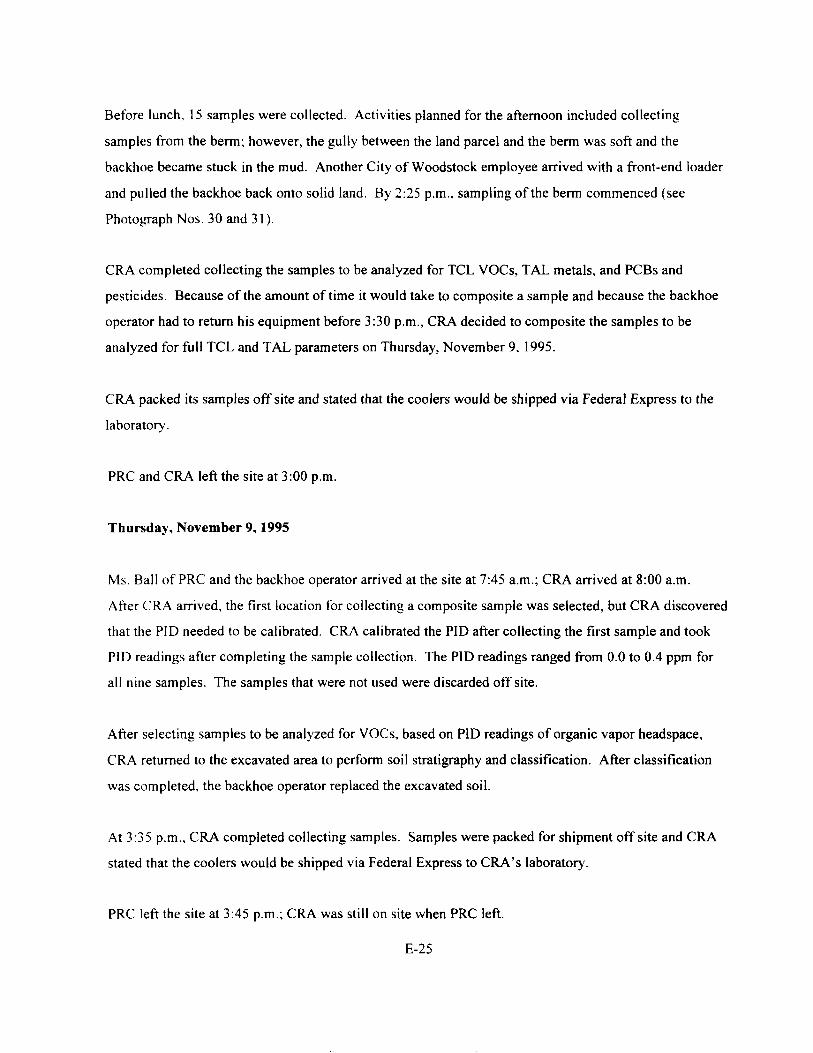
Before lunch, 15 samples were collected. Activities planned for the afternoon included collecting
samples from the berm; however, the gully between the land parcel and the berm was soft and the
backhoe became stuck in the mud. Another City of Woodstock employee arrived with a front-end loader
and pulled the backhoe back onto solid land. By 2:25 p.m., sampling of the berm commenced (see
Photograph Nos. 30 and 31).
CRA completed collecting the samples to be analyzed for TCL VOCs, TAL metals, and PCBs and
pesticides. Because of the amount of time it would take to composite a sample and because the backhoe
operator had to return his equipment before 3:30 p.m., CRA decided to composite the samples to be
analyzed for full TCL and TAL parameters on Thursday, November 9, 1995.
CRA packed its samples off site and stated that the coolers would be shipped via Federal Express to the
laboratory.
PRC and CRA left the site at 3:00 p.m.
Thursday, November 9, 1995
Ms. Ball of PRC and the backhoe operator arrived at the site at 7:45 a.m.; CRA arrived at 8:00 a.m.
After CRA arrived, the first location for collecting a composite sample was selected, but CRA discovered
that the PID needed to be calibrated. CRA calibrated the PID after collecting the first sample and took
P1D readings after completing the sample collection. The PID readings ranged from 0.0 to 0.4 ppm for
all nine samples. The samples that were not used were discarded off site.
After selecting samples to be analyzed for VOCs, based on PID readings of organic vapor headspace,
CRA returned to the excavated area to perform soil stratigraphy and classification. After classification
was completed, the backhoe operator replaced the excavated soil.
At 3:35 p.m., CRA completed collecting samples. Samples were packed for shipment off site and CRA
stated that the coolers would be shipped via Federal Express to CRA's laboratory.
PRC left the site at 3:45 p.m.; CRA was still on site when PRC left.
E-25

Friday, November 10,1995
At 9:15 a.m., Mr. Kevin Schnoes of PRC arrived at the site to oversee the pump test and met with Mr.
Pochron of CRA. Mr. Pochron informed PRC that the first step of the step pump test had already been
conducted. CRA stated that, during the first step, EW-1 was pumped at a rate of 6 gallons per minute
(gpm) for 1 hour. CRA began the second step of the step pump test at 10:30 a.m. Based on the data
from the first step, CRA decided to pump EW-1 at 4 gpm for 1 hour during this next step. CRA installed
data loggers (see Photograph No. 32) in the following piezometers and wells to monitor water levels
during the step pump test: PZ-1, PZ-2, PZ-3, MW-4D, MW-8, and MW-12. The water level in EW-1
was measured manually during the step pump test. Water pumped from EW-1 was contained in a 500-
gallon plastic storage tank (see Photograph No. 33). The water was then pumped to the Woodstock
municipal wastewater treatment facility located adjacent to the site. CRA concluded the second step of
the step pump test at 11:30 a.m.; however, before turning the pump off, CRA collected a water sample
from EW-1 (see Photograph No. 34). Samples were collected to be analyzed for VOCs, SVOCs,
phenols, pesticides and PCBs, cyanide, and total metals. No further steps were conducted during the step
pump test. Mr. Pochron of CRA calculated an average pumping rate of 3.9 gpm and a drawdown of 7.2
feet bgs in EW-1 during the second step of the step pump test. Mr. Pochron stated that a pumping rate of
4.5 or 5 gpm would be used during the 72-hour pump test, which would be conducted tomorrow.
PRC left the site at 1:00 p.m.
Monday, November 13, 1995
Mr. Schnoes of PRC arrived at the site at 10:45 a.m. to oversee the 72-hour pump test. The pump test
began at 11:00 a.m., with EW-1 being pumped at a rate of 5 gpm (see Photographs No. 35 and 36). Data
loggers were installed in the same wells as those used during the step pump test (see Photographs No. 37
through 40). CRA personnel were also manually measuring the water levels in these monitoring wells so
that the water levels could be measured and confirmed during the data analysis. Water levels in EW-1
and MW-4S were also measured manually (see Photograph No. 41) and in two drive points that were
installed near EW-1 (see Photograph No. 42). The drive points were screened from about 3 to 5 feet bgs
and were installed to determine if water levels in the nearby wetland were influenced by the pump test.
In addition, the water level in the Kishwaukee River was measured at a staff gauge installed near MW-4S
E-26

and MW-4D (see Photograph No.43). Drillers from Boart also checked the pump flow rate every hour
during the test (see Photograph No. 44).
During the pump test, Mr. Pochron of CRA collected three surface soil samples from an area west of the
site support trailer (see Photograph No. 45). The samples were collected to determine if wastewater
treatment sludge had been spread in the area.
"KRC 'left the site at 4:45 p.m.
Tuesday, November 14, 1995
Mr. Schnoes of PRC arrived at the site at 10:15 a.m. CRA personnel stated that the pump test was
progressing according to plan and that no problems had occurred. CRA continued to manually check
water levels in the monitoring wells, piezometers, drive points, and staff gauge. The drillers also
continued to check the flow rate hourly. At 11:35 a.m., CRA collected a water sample from EW-1 (see
Photograph No. 46). This sample was collected approximately 24 hours from the start of the pump test
and was to be analyzed for the parameters previously described.
PRC left the site at 4:30 p.m.
Wednesday, November 15,1995
Wir. 'Scnnoes o't'FR'C, arrived at fne site at "lt)fUD a.m. URA personne'l stated that the pump test was
progressing according to plan and that no problems had occurred. CRA continued to manually check
water levels in the monitoring wells, piezometers, drive points, and staff gauge. The drillers also
continued to check the flow rate hourly. At 11:20 a.m., CRA collected a water sample from EW-1. This
sample was collected approximately 48 hours after the start of the pump test.
PRC left the site at 4:30 p.m.
E-27
Thursday, November 16, 1995
Mr. Schnoes of PRC arrived at the site at 10:00 a.m. CRA personnel stated that the pump test was
progressing according to plan and that no problems had occurred. CRA continued to manually check
water levels in the monitoring wells, piezometers, drive points, and staff gauge. The drillers also
continued to check the flow rate hourly. At 9:45 a.m., CRA began collecting a water sample from EW-1.
Additional time was required to collect the sample because it was a matrix spike/matrix spike duplicate
(MS/MSD) sample and additional sample volume was required for the MS/MSD sample. This sample
was collected approximately 72 hours after the start of the pump test. All samples collected during the
pump test at EW-1 were to be analyzed for VOCs, SVOCs, total phenol, total metals, pesticides and
PCBs. cyanide, total dissolved solids (TDS), total suspended solids (TSS), pH, oil and grease, chloride,
and fluoride.
At 11:00 a.m., the pump in EW-1 was shut off and the pump test was complete. CRA personnel then
began to periodically monitor the recovery of water levels by manually measuring the water levels in
"E'vV-'l and'IVTvv'-li (seefhotograpVrto. 4T). "Data'loggers'instai'iecTin line we'i'is also continued to measure
water levels during the recovery monitoring.
PRC observed no significant problems or deficiencies during its oversight of the pump test.
At the end of the pump test, the final drawdown in EW-1 was about 8 feet from the top of the white pipe
in EW-1. Mr. Pochron of CRA stated that there were water level responses in all of the wells which were
monitored due to the influence of the pump test. In addition, water levels in the two drive points near
EW-1 ini t ia l ly dropped; however, the water levels in these wells reportedly did not decrease further due
to the pump test. In fact, water levels in the drive points reportedly rose during the pump test, probably
in response to recharge from precipitation. CRA planned to monitor water levels during the recovery test
u n t i l 80 percent of the prepumping water level was achieved. This level, however, was not achieved
when PRC' left the site.
PRC left the site at 11:30 a.m.
E-28

SUMMARY
From June 28 through November 16, 1995, PRC conducted field oversight of (1) the borrow area soil
sampling at Precision Quincy and D.B. Hess facilities in Woodstock, Illinois, and (2) the predesign
investigations at the WML site performed by CRA. Generally, PRC observed no significant problems or
deficiencies. Problems that were encountered were resolved before work proceeded, as described.
E-29

APPENDIX A
PHOTOGRAPHIC LOG
(24 Pages)

Photograph No. 1 Location: Precision Quincy Site (PQS)Orientation: North Date: 06/28/95Description: Northern portion of borrow area showing vegetation
Photograph No. 2 Location: PQSOrientation: North Date: 06/28/95Description: Conestoga-Rovers & Associates (CRA) personnel collecting soil samples from a soil
pile
A-l

Photograph No. 3Orientation: NorthDescription: Typical test pit showing soil strata
Location: PQSDate: 06/28/95
Photograph No. 4Orientation: NorthDescription: Potential borrow area east of the existing structure
Location: PQSDate: 06/28/95
A-2

S^^ffi^SS^Wr^;^W-frJBFV^ • -. '•*". -'f^*.* - •*$.
Photograph No. 5Orientation: NorthDescription: CRA personnel collecting subsurface soil samples
Location: PQSDate: 07/07/95
Photograph No. 6Orientation: NortheastDescription: CRA personnel advancing a split-spoon sampler
Location: PQSDate: 07/07/95
A-3

Photograph No. 7Orientation: NorthDescription: CRA personnel decontaminating the power auger
Location: PQSDate: 07/07/95
Photograph No. 8Orientation:Description: CRA personnel drilling with a power auger
Location: PQSDate: 07/07/95
A-4

Photograph No. 9Orientation. WestDescription: CRA personnel cleaning the backhoe bucket
Location: PQSDate: 07/10/95
Photograph No. 10 Location: PQSOrientation: East Date: 07/10/95Description: CRA personnel conducting a headspace reading of volatile organic compound (VOC)
samples with a Microtip photoionization detector (PID)
A-5

PhotographNo.il Location: MW-6SOrientation: Northeast Date: 09/12/95Description: Flushing monitoring well
(MW)-6S with about 30gallons of water to removesoil and paniculate that wasblocking the well
Photograph No. 12Orientation: Southwest
Location: MW-6DDate: 09/12/95
Description: Boart Longyear (Boart) personnel excavating soil surrounding MW-6D
A-6

Photograph No. 13Orientation: SoutheastDescription: Location of MW-6D after it was abandoned
Location: MW-6DDate: 09/12/95
Photograph No. 14 Location: MW-14Orientation: East Date: 09/12/95Description: Boart personnel drilling borehole for MW-14 with a hollow-stem auger
A-7
Photograph No. 15 Location: MW-12Orientation: West Date: 09/14/95Description: Boart personnel drilling borehole for MW-12 in the exclusion zone
Photograph No. 16Orientation: WestDescription: Boart personnel removing the augers at MW-12
Location: MW-12Date: 09/14/95
A-8

Photograph No. 17Orientation: EastDescription: Boart personnel decontaminating hollow-stem augers
Location: WML SiteDate: 09/14/95
Photograph No. 18Orientation: WestDescription: Drilling pilot soil boring at EW-1
Location: Extraction Well (EW)-lDate: 09/19/95
A-9

Photograph No. 19 Location: Soil boring (SB)-115Orientation: East Date: 09/19/95Description: Whitish-gray sludge seen in tire tracks along the south side of landfill near SB-115
Photograph No. 20Orientation: NortheastDescription: Boart drilling at SB-77 on Davis Road
Location: SB-77Date: 09/25/95
A-10

Photograph No. 21 Location: Gas probe (GP)-5Orientation: Southwest Date: 09/26/95Description: Installing a polyvinyl chloride (PVC) gas probe at location GP-5
Photograph No. 22 Location: EW-1Orientation: West Date: 10/02/95Description: Boart preparing to drill EW-1; photograph shows drill rig jacked up to accommodate
10-3/8-inch augers
A-ll

Photograph No. 23Orientation: EastDescription: Boart drilling a pilot hole with 4-3/8- inch auger
Location: EW-1Date: 10/02/95
Photograph No. 24Orientation: SouthDescription: Collecting samples from MW-1S
Location: MW-1SDate: 10/17/95
A-12

Photograph No. 25Orientation: WestDescription: Collecting subsurface soil samples using a hand auger
Location: S-lDate: 10/17/95
Photograph No. 26Orientation: SouthDescription: Soil sample being mixed in a stainless steel bowl
Location: S-2Date: 10/17/95
A-13

Photograph No. 27 Location: GP-1Orientation: West Date: 10/24/95Description: CRA personnel measuring combustible gas concentration in a gas probe
Photograph No. 28Orientation: SouthDescription: Backhoe operator excavating a pit at location Al
Location: D.B. Hess SiteDate: 11/07/95
A-14

Photograph No. 29 Location: D.B. Hess SiteOrientation: South Date: 11/07/95Description: CRA personnel collecting soil samples from a soil pile at location Bl
Photograph No. 30 Location: D.B. Hess SiteOrientation: Southwest Date: 11/08/95Description: Berm where samples from locations G8 and H8 were collected; D.B. Hess loading
dock is seen in background
A-15

Photograph No. 31Orientation: NortheastDescription: Sample location H8; employee parking lot is in background
Location: D. B. Hess SiteDate: 11/08/95
Photograph No. 32 Location: MW-12Orientation: West Date: 11/10/95Description: Data logger in MW-12; set up is typical of that used in monitoring other wells during
pump test
A-16

Photograph No. 33 Location: EW-1Orientation: East Date: 11/10/95Description: CRA personnel measuring water level in EW-1 during pump test; water level is
measured from top of white pipe; data logger in MW-8 and holding tank for pump testwater in background
Photograph No. 34Orientation: NorthDescription: CRA personnel collecting water sample from EW-1
Location: EW-1Date: 11/10/95
A-17

Photograph No. 35 Location: EW-1Orientation: East Date: 11/13/95Description: Pump test set up at EW-1; holding tank for pump test water in background
Photograph No. 36 Location: EW-1Orientation: West Date: 11/13/95Description: Pump test set up at EW-1; monitoring wells and piezometers used to monitor water
levels during test seen in the background
A-18
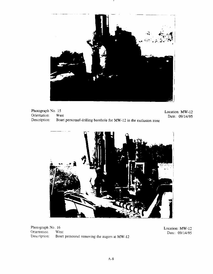
Photograph No. 37 Location: MW-4SOrientation: North Date: 11/13/95Description: Pump test monitoring set up at MW-4D (left); data logger used to measure water level
shown; water level in MW-4S (right) measured manually during pump test
Photograph No. 38 Location: Piezometer (PZ)-3Orientation: North Date: 11/13/95Description: Pump test monitoring setup at PZ-3; data logger and electronic tape used to measure
water level shown
A-19

Photograph No. 39 Location: PZ-2Orientation: East Date: 11/13/95Description: Pump test monitoring setup at PZ-2; data logger and electronic tape used to measure
water level shown
Photograph No. 40 Location: PZ-1Orientation: East Date: 11/13/95Description: Pump test monitoring setup at PZ-1; data logger and electronic tape used to measure
water level shown
A-20

Photograph No. 41Orientation: EastDescription: CRA personnel measuring water level in EW-1 during pump test
Location: EW-1Date: 11/13/95
Photograph No. 42 Location: Drive point (DP)-lOrientation: South Date: 11/13/95Description: CRA personnel measuring water level in drive point DP-1 (orange pipe); drive points
DP-1 and DP-2 were installed near EW-1
A-21

Photograph No. 43 Location: Staff gaugeOrientation: North Date: 11/13/95Description: Pipe (staff gauge) used to measure surface water level in Kishwaukee River
Photograph No. 44 Location: EW-1Orientacion: South Date: 11/13/95Description: Boart personnel checking flow rate of pump during pump test; CRA personnel
measuring water level in EW-1
A-22
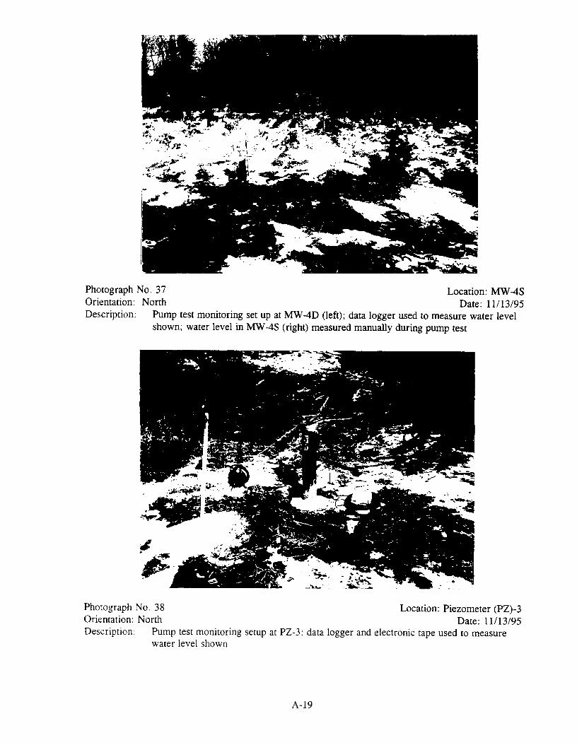
Photograph No. 45 Location: West of site support trailerOrientation: South Date: 11/13/95Description: CRA personnel collecting surface soil sample from area west of site support trailer
Photograph No. 46 Location: EW-1Orientation: North Date: 11/14/95Description: CRA personnel collecting water sample from EW-1; sample collected approximately 24
hours after pump test was started
A-23

Photograph No. 47 Location: EW-1Orientation: South Date: 11/16/95Description: CRA personnel measuring water level in EW-1 and MW-8 during recovery monitoring
A-24

APPENDIX B
FIELD NOTES
(97 Sheets)

Field Logbook No.
Project No. .... _._
Date
1 2 : „ K
o X1
J*&l
0<
?Wp w »~? ,^
4)
•ox?
62
Field Logbook No..__ ......
Project No. __________ __
Date
ft
«v»c/l rA«. i /-re* *v*eM <v^/i ! . /' I i '
k-
'/I<Y/4p/frl
^>i
; c/l\"Jy i
cf
/'
63

Field Logbook No.
Project No. ._.._
Project Name
Date
I
\e >
««
e* f
r
it
^<t c&y*/y\t/<\,H**( p/\(
Field Logbook No.
Project No. ———
Project Name
Date
..// -

Field Logbook No.
Project No.
Project Name
Date Field Logbook No.
Project No.
Project Name

•m'^ ?JPW.
Field Logbook No.
Project No.
Project Name
Date
SVt-v/ss Sk
/./
Field Logbook No.
Project No. ,.;t.__.
Project Name
* jf-
/
66
. :• vaNNUM;*'!jt'-'fe~'* i\yM
Date
(;f70
x^^

^v™' f***
:><+ •*..
Field Logbook No.
Project No.
Project Name
Date Field Logbook No.
Project No. ___._.
Project Name _ _ _ _ _

Field Logbook No.
Project No.
Project Name __
Date
Me*
Field Logbook No.
Project No. _____
Date
Project Name.
-r/,s rtf4^c/.r
^y.
l/€
T>(t(
(
Jt-u«*
c ?*»~f/lf
ffi>p:% U
^?
fi(fr
72
3
"'-;'
5V
r/j>ky
AX-
J'«
--re
T*r-
T/><
M
^
C/A
73
J
Field Logbook No.
Project No.
Project Name
0 ~i,-./
0-6"6 f/r- C r
yI
// ._
Date
y
74
Field Logbook No.
Project No. . ._ . . . . . ._
Project Name
b-{''- 2
?6
Date
**\
"la- jyL
r> ( ff QL
y
75

Field Logbook No.
Project No.
Project Name
DateField Logbook No.
Project No. _.___._
Project Name._._
Date
77

Field Logbook No.
Project No.
Project Name
r '<-
y
7C
Date
/fcf*
yd /-'
•/ir
y
78
Field Logbook No.
Project No.
Project Name _
f t
'/fa
•/,4
fy
Date
V*
ys~~~ 6 '/
c.
)'/«,-•1*4 A
*\h
79

Date Field Logbook No.
Project No. ._...._
Project Name _____
Date
a
tf
{je
-v
i i
to
/(W
iAf ^
/

/.. M
Field Logbook No.
Project No.
Project Name
Date Field Logbook No
Project No.
Project Name
ti\c. l/^L^f' C^

DateField Logbook No
Project No.
Pro|ecl Name
Field Logbook No.
Project No.
Project Name
Date
~ f i
S-
;tt 4
','*-*/
> f
/
/4
fc<~
r
6.
?, '
•f'**\6
^cf*/
&VI
f/fr
&«
c )
85

Field Logbook No.
Project No.
Project Name
Date Field Logbook No.
Project No.
Project Name
Date
/*"f/4/ ft&&
i° r tfb ^Ji^L^/.\ j • i ' i
86
Field Logbook No
Project No.
Project Name
Date Field Logbook No.
Project No.
Project Name
Date
W
P\
/*>,'/
89
A i t>
4
* C
H
f
A t>

Field Logbook No.
Project No.
Project Name
Date Field Logbook No.
Project No. _ _.
Project Name
Date
ert
•*•*/-•
SC/
P
('AS 1

Field Logbook No.
Project No. ____
Project Name
Date
4JT-*
••**••• -.ai '.-'**> ' '4'J »>?.*> ^ t • .- w
Field Logbook No. _____. __ __ Date
Project No. __ ________ _______ ._.._
Project Name __________________
r^;rj-f-
»4 ^>J
/r
93

Field Logbook No.
Project No.
Project Name
c*f. ft"
I/''A
Date
At.
'fa
94
'b
Field Logbook No.
Project No.
Project Name
Date
tc!
O*0£ n*\f
^
ivy?,
fifotffa
HV
'/
95

fc^TTr.'.*
te"s-
FteM Logbook No.
Project No. _ _ _ _ _ _
Project Name __
Date Field Logbook No.
Protect No. __
Project Name __
£

Field Logbook No.
Project No.
Project Name
Date
/?Bc
9 AB
. c0
P
/<? ADc1}
c0
BcO
?<<-<•?
Field Logbook No.
Project No.
Project Name
Date
f
/g
98$ A'**? 99

Field Logbook No.
Project No.
Project Name
Field Logbook No.
Project No.._._
Project Name
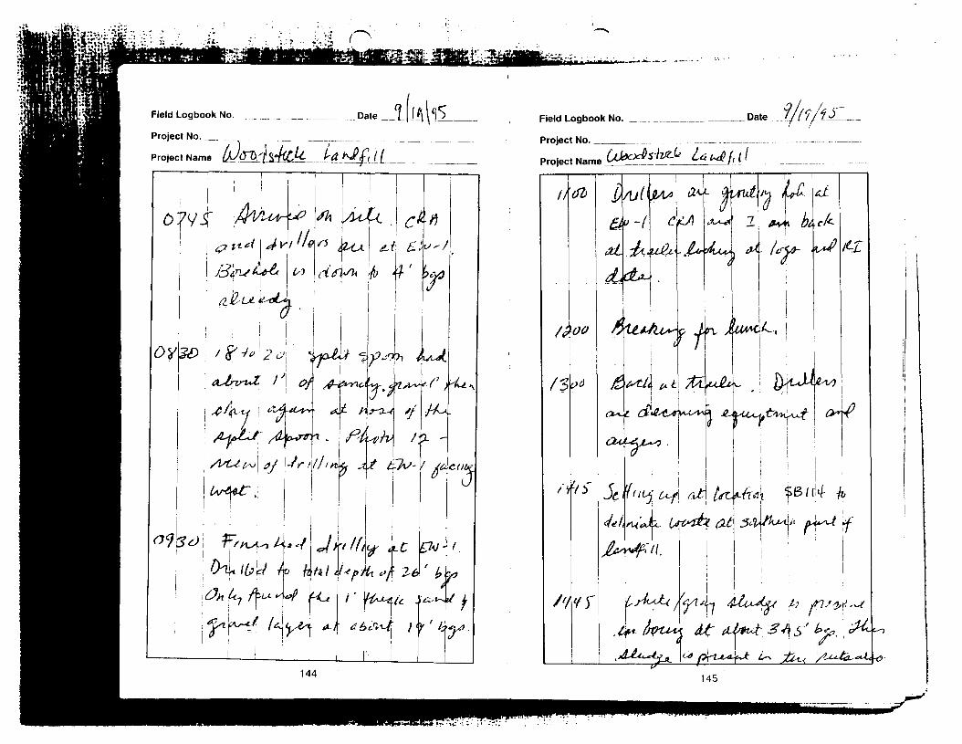
Field Logbook No.
Project No. _._
Project Name

Field Logbook No. _ _ _ _ _ _ _ _ _ _ _ _ _ _ _ _ _ _ _ _ _ _ _ _ D a t e
Project No. _ __ _.__ ___ _
Project Name _ »tf^U)^Cfe- f-fr\rtP
X* 6
/,
ji^•&/'
Vt*hf* 5j5 it 5"
B/"51
/5"
- / AW
5
^5 / /<J
'//<t>
fJiS
f
Field Logbook No.
Project No. _____
Project Name
Date iMI^
146 147

Field Logbook No.
Project No. ___
Project Name ljOp.0 (4'^VDCl^
Date
148
Field Logbook No. __
Project No. ___.._.__
Project Name Vxj (; 0
Date
i&JL
r'
;<*
ZV;
SL&
5"
. J4nc
$ -WA*><
Wtyfirt
fak
C4V
/4
/
149 ^7
T«rfi,

Field Logbook No
Project No
Field Logbook No.
Project No. _
Project Name

Field Logbook No.
Projecl No. _ _ . _ .
Project Name
.__ Dale
152
Field Logbook No.
Project No. ____
Date
Project Name \^)0 OC\ s4t£ <<C La V-A f 11 |
CXV\bsr\^
to
&XfW^
cT
50' /UCM
r U16
3-?
153

Field Logbook No.
Project No.
Project Name
/"XT
Dale
//I4w
L5#k^
^«^>*u/
A/U/^fct^k
/ 7t^fT
154
Field Logbook No
Project No
Date
155

Field Logbook No.
Project No.
Project Name _..
Date
\
Field Logbook No.
Project No. ________
Project Name __
.Date ._. ______
156 157

Field Logbook No
Project No.
Project Name
Field Logbook No.
Project No. ._._..
Project Name
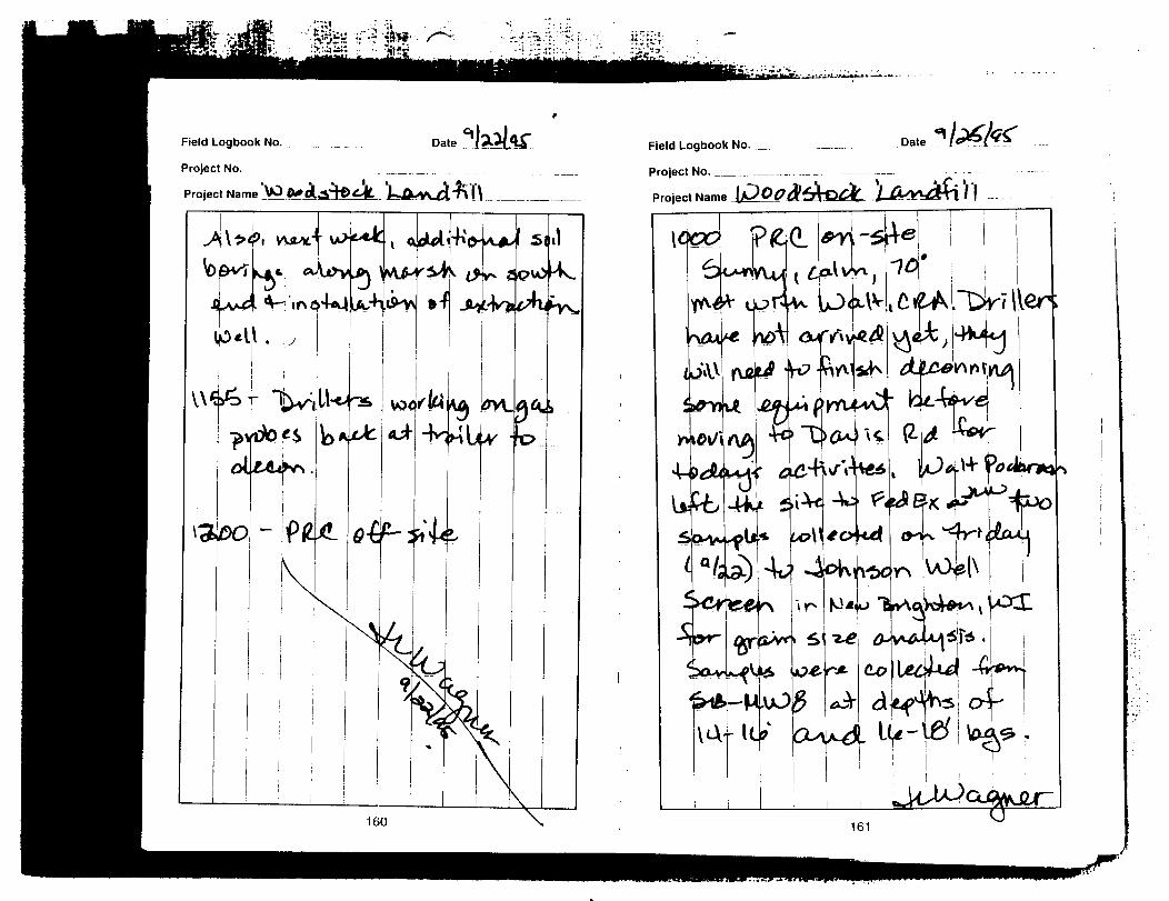
Field Logbook No.
Project No. .......
Project Name ^VO 0+
Dale
160
Field Logbook No.
Project No. _____
Project Name
Date
$m*
QJf
Hu
tfmf^\\
•^£0"Ul
4iohv&4"
C«?A.~Drlftert\{p^j
w- f«
(U?
f*r4161

Field Loqbook No.
Project No. .
Project NameProject No.
Project Name iJjJfld
M* &.

gjajMSrr-V ji ~.--f.'f-.: n.tj!t3fn-:Mi*\l~-~'*," •• ••• ———- -'
Field Logbook No. _ . _ . _ _ _ _ Date
Project No. __ ... _ _ . _ . _ _ _ _ ________ __
Project Name tfj><&d^OfJ^J fMA^^\ )
•^ 4o
^eaj
Koj
4<p>U0od
-fed <a^e ine^-o^Oucf
^OOp<>rH\u?estu
Field Logbook No.
Project No. ___
Project Name
13-ic?--ji*>-
Date
KftJi:
-dO - Ad)
C 1
^e^J
T vn(?
\e^-^fc-
rAjov^f*Avrt*Yo>*^€rs
40165

Field Logbook No.
Project No.
Project Name
Dale Field Logbook No.
Project No.
Project Name
Date
IH
i*.4lot.
6*
toff I also
olrtl/ format
of l
cs
55131,-
166 167

Field Logbook No.
Project No. _ _ . _
Project Name
Date Field Logbook No.
Project No.Date
169

Field Logbook No. _ ._.. _ _ Date
Project No. _ . . _ . . . . . _ ______..._..._.-
Project Name
6
071/5-• \
titpitifj
**+
. V * ZA
//
'*»* 2
!^ ' j/»
//co $ei
170
Field Logbook No.
Project No. __._._._
Project NameT
&
Date
S/ ft. '"A

Field Logbook No.
Project No.
Field Logbook No
Project No. _
Project Name

J9E.
Field Logbook No.
Project No.
Project Name
Dale
*'T
12,} i>
£-
•f
174
Field Logbook No.
Project No. _..._.
Project Name _ __
Date
-M
f•/<
i i
J.'-^
.r;
5'
;# ••*+<> .V : , \ ,
, I . Ly/*ry*^ / •
f*c&'•
175
•3$ife; t---M **.

fe-aSr-jjim? .> 'j-'_.-_:
Field Logbook No.
Project No . _ _ _ _ _
Project Name .._.__
Date
$6»l
J4"<
f*M
tfZo
41*4.I
j
jf?d\
/£'
•w.
&B*f
0"
A>
;'
lU-t
r-f
£&.
4*
•
y.-
.-A
#'*
Field Logbook No.
Project No. ______
Project Name
Date
^-ft>
IWto
*k I
rfy.
***!'4*4
rfL**4
***,
faji*£) ffyn.
o^f•^r'ttU^aa

Field Logbook No.
Project No.
Project Name lP »0d
Field Logbook Ro.
Project No.
Project Name
Date
**» •«*•

Field Logbook No. .
Project No. _.__
Project Name J
Date
r#-»
it
T. / ! »>
rHt\^>^
\W>0
*+4
\t> b~ t?
• i l l
fr^v
->4*49i--
pt^L^ -
U^
«-^e^
-1
180
Field Logbook No.
Project No. _____
Project Name _^j
Date
\*:
*O
t bt
U
o<b
Sc-w/f
IP'
fiC
f*<*.
<dri
IV
196
±z4
^r
*<&_
181

Field Logbook No.
ProjecVNo.
Project Name
Date
/^
'/))•
;^'^y
•^ 1 *^T^
H"
|P
'r
rt- fV
\,
'
A^ 1C?l
XX
^
*•!
k
-•T
LL
Q<T^
(.jjyv.
182
Field Logbook No Dale
Project Name
45
/U4u<
<W
•faf
no
e>W<^
,.{>
Al
*K
y /**</
^r |.
-f/W-/ >4 H^»-t ^ ^i«fc Jfr"*j* ^-,
jt«ft»
r
f!183

Field Logbook No. __...
Project No. _ . . ._ .._..„_._ _.._.._____
UJ0+*»tvct^ t~**fillProject Name
Date '1*1*
IW
to
*$**
*.'
Ttip
/My
W
I miv-
M<* fi
/Vi >
M4.
lo
Field Logbook No.
Project No. ___10
184

Field Logbook No.
Project No. .
Project Name
Date
186
Field Logbook No. __
Project No. _._ ___
Project Name _lt)_£££[
Date
b&Ol
Kv-
1'
Jt
1:
r ^ /:
ott-f*
joi O
10:o^.&Cl
187

Field Logbook No.
Project No.
Project Name
Date
MV
\\
rr-Wut/
80 3*I41
urJitee
\*
^
!
>>>'U36
w.
^
| i uc j r iv1 i
LUAA_/r,
iTIf
). "-Vvnoo! ^
J\\ -fl
:ae«i-i
r -N._ .
f
LA€
) 'o-^'ifLf AV*-f
x^l-iy^
T
5U^
*>Q^M
•C-''
>
>m
5»rA\
_ c
-^£+*
\«vA-
TV
> \Jb
ngr*
^1 T1 —
teto* -• 2T
,jrto-
>*ir
) .
188s
Field Logbook No
Project No. _____
Project Name
Date
189

Field Logbook No.
Project No. _ . . _ _ . . _.
Project Name
Field Logbook No
Project No.
Project Name

••-" --
Field Logbook No.
Project No.
Project Name UJ
Date lt)lt\fi<5

PRC Environmental Management, Inc.
Field Logbook No.
Loqbook No.
(For Single Project Use Only)
^
Project No.:
Project Lc
Site ID/GI
IssuanceNo.
.cation: LJ ™**«fe*fc La^dG M S4*
3S: '
Date NameLast Page
Used
3.30


Field Logbook No. -4--'-


Field Logbook No.
Project No.
I Project Name I
Date l^ l>')l !*>
' /.-c
Cfl/j
// /«
<<'i j'
y
58
/-*•'<••
Field Logbook No.
Project No. _ _ _ _
Project Name _
-kt
Date
tv/v
t}*']?/*
j*/.'t^rYf' /
| ,_j
59

Field Logbook No.
Project No..____
Project Name ._.__
Date Field Logbook No.
Project No. _____
Project Name
/J,
t £ * fl</ fa'.^ __ _____
717
t"
61
* -*^;fli.*,<t. '
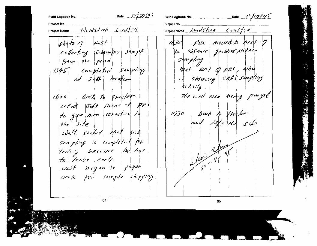
Field Logbook No.
Project No ___
Project Name _ Project Name /.>W/'/*t/*

TH"..V;-its ......•.-.^Hi-
Field Logbook No L)mi(s/-*ok. A*ffi/Datft ^
/t ?
^ /X f eS*(( 9*ttf //&(/;*!*«+•>
*tt>'
Field Logbook No. .Date.
SO
us.'
5" Alf //
o-r^-f 1-*
f
>'»<?
I

10
Field Logbook No.
II
**
* - X « r titffrs
.Date.
\ A
Field Logbook No.
ft'
11.Date.
-fif-
ot</

ii£*U r..- ..i r^
12
Field Logbook No.
13
/•* A4.
.Date
foir
Field Logbook No Date.
H.,.-.. , .. .-,»,.,„ .;„._.

PRC Environmental Management, Inc.
Logbook No.
(For Single Project Use Only)
Project N
Project L(
Site ID/G
IssuanceNo.
o.: 030~ooT7fc_S
acation: UD o e d sW-t 5 -H /
PS:
b*j£. C&v^ V- T^kfr^Wu>«JM^S
Date
"/>*^
_,..,. ... t
Name
^e« Sc ,
K ____ ftrt|
Last PageUsed
~r
Field Logbook No. .Date.
i t l j - 'V1 ' ' - b ()•']/
)~v\Jc>-
ilt'.:* J, r
^ s •I 'V
I" ' I
Vt'v
/<iv
'«?
f ! j" '11' ^/
a

Field Logbook No. _Date.
Jj
Ti
-(i
IV
UL>"u
d<i-
r
6'
M•7?
\ g - f c "
iws
S
p,'4f""(UiT
t,
Field Logbook No. Date.

>A ^ >. <L"s_.. - ?._.i—.._ o ....
D
——— fr-
1a .... -o .T.. __•-_..
T ~ ^fejL.^_^. -x
"0
VN
1 _p. c » .
v t_ : -T. -=«.. <J \i £ A! r-'^^^fc'c—^""^

Field Logbook No. _uate.
I/OO
J-
L^Wt
27/3
•n. VI1?
.D).
l-J2^^/
,.J\
i'S
C/5
•7-0
: S
-T/f*1
! I i/ 1"3
•U-ilJb^ S ('
Us,-? IA/I. :.as'i n/f!)
^ .
'FnJnb'myuudK^.
"/j' rl•|t
ko
.Q^ft.
cjUJM M/
.
S.5U^
-•flj,S,W
P4 an
H~#
#
-6'
ic\ .
:
cU/
C9
T'W^,ff
^TV
fe

Field Logbook No. _
"f ~
.Date.
H
' jfyv-itn-t., (i i
3
n
ALr
wa^t
A
K
1l/^fi^r
73.
! « ' - i 7 2 ; '^A ' i l ( r~*7' /_c - '_, C t
xiL*- 't
Field Logbook No.
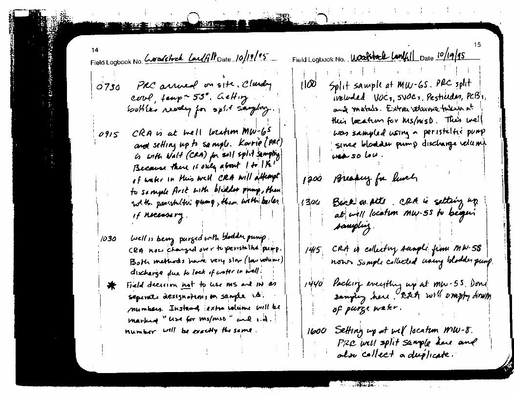
. ...; -T«k-•IttfcS8*-- ll ' „ ,-:r»- .-
14
Field NO.
Sttiliy ttf A
IM
V- *-
4t>
x' Uv«
fa*
Field Logbook Mo.. lA/Wagp^c*
19-00
CM
irr. M
15
i i
"i
; ^
o

17
Field Logbook No. Date
i i

.-„,_... -a.- . ...*ifMfc -, *Hfr »

12
Field Logbook No.
m

VK &
•*•"- ">*-
1-1
Field Logbook Mo. 3_
tr.

~-\:y
;*r'v
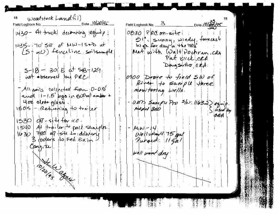
Field Logbook No. Date Field Logbook No.
!H;.-I: •v- •••••

20
Field Logbook No.Field Logbook No.
J:i i
ouf .
21

22 t«-
Field Logbook No.
.15
£*uvn.
> V
r^
v^
t-n-
X
\
*K•cc
r v
J
y

22
Field Logbook No. _i_ pg«0 io|j.&ke
.-.
1 4
- ——
__..
•k
<\s,
YYV
>\
—
- -
r^^t U.
,»
^
-
*K•cu
r v.
j
\- V
Vpt
€Vf
iv^
. L. I
*li>^WMju
?
^\ !\!
\
23
Field Logbook No.
MI-
j? .Date. ie>/ztt/tf—
Ui«
flC
P*
S*
^5// J
^«
-»»*'
p^ryi'
,r
t/^*
^•*f«'«4^T
J«A*
H /!
o

Field Logbook No.
'**
tj^
Field Logbook No.
feA
•**Lci i
r *••v f-(fri-/:*»v
^^h
r*f r^i
y« -K*<u
I 'I ! IM^**
27 ti-ll
4*7
<//*«
! 1w>
'
^•WW-rwr--r -•-/

28
Field Logbook No3T
.Date. Field Logbook No. .Date.
M*
ft
•«.
'tfre
v./
' 4 .
/*
Vrr K-
i/ok
L, a
H •
*x/*a
T r
t. f/•^«4c
*/^
^
JLSTP
'A«lr/I* I
. . . . . . . . . r __- j ...-r_..-/b| (^UP «da M
i i !
s^y/4^xU
q/fc^
i if
r/"*6^
l tl
i.sir///J
29

Field Logbook No
Project No. __
Project Name __
Date Field Logbook No. ___^__ Date
Protect No..
t / Project Name /««</£//
? P
0cJt*-c**J
/'Cfc
S*/-6f^
<l/t/j•••^ A
3
/i
fa
r
^,/A;
48
C!
rV
c*
,'Pi
8*
£*
. cy
49
4
i1 '•/>''
. 4t .
*t'i
1't
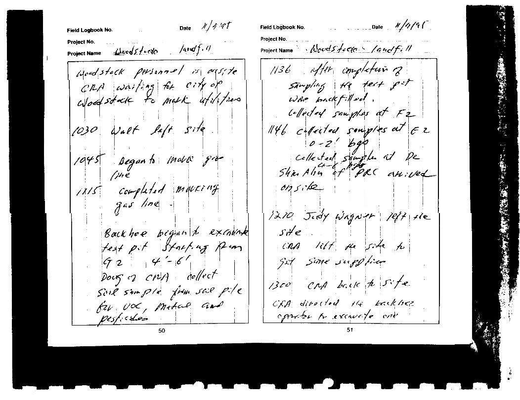
Field Logbook No.
Project No.
Project Name . .
////T
Date
'
JTi /
50
Field Lbgbook No.
Project No.
Project Name
Date
y
*'
.<
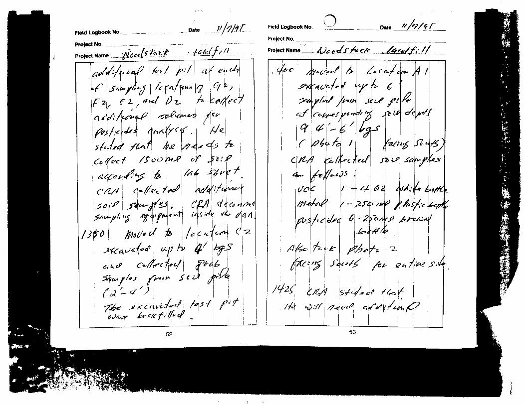
, *N,
«W«*e»'
Field Logbook No.
Pro|ect No. _____
Project Name ___. .
Date
~&*
A
r/^j
/
^«^TT /vkr'</<n "• ^ i/*/
52
C
Field Logbook No.
Project No.
Project Name • ••
O
r^4-^
U
^J
/
/'/*?
4
r
-2
S'
53
c/JXJ
la.V'
^

Field Logbook No. __
Project No.
Project Name /*4W *" / *C£
//<
Date
d f>
Field Logbook No. ________
Project No. _____________
.Date
Project Name &£———..
A
55
ifc
l»W,-
^:; •.* /

Field Logbook No.
Project No. _
Project Name
U..eField Logbook No. __ _____ Date
Project No. ______
Project Name __

30
Field Logbook No Field Logbook No. ->
C£
i! ,J/, ,1 \ •!
/hl^T^flJi. - Vl-T.cH
IIklii31
j ~T
• J^-J'-f*
u
(L
6«U*1 0Jhi
/An'tfl
CU
I'JtK'''.'^
OS-.. (
k«>-v;^,K>-. L
/
• »•-' /•;/.-i iI I I .
;yu- ! ^»c' v ( 1 1 c.o •, ., r,<., r i , --"
/. . 7 _/,,.T. ,.
i ^ i


34
Field Logbook No. Field Logbook No -3 Date A # 1? !>
35
r
us»r
2*'-O.
f-U
lieL_
Oi4
&
23.
-?&?.*m-


40
Field Logbook No

it*
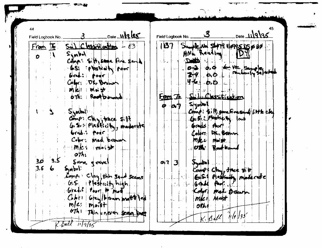

47

?i--' -. - • - • ' • "„»•••„•.-? . j •:..-•] vr'./i' i v »•* -*.'.-i


t_ _ J1 Ikl I

<r/o~
V
\Jo*yL&Aj~Vo
J$
'5/<".

CJo3
d
orooo
t
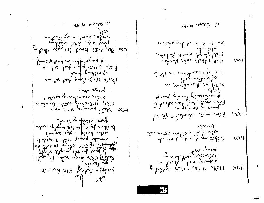
• ffT^Y
~ ^) I,
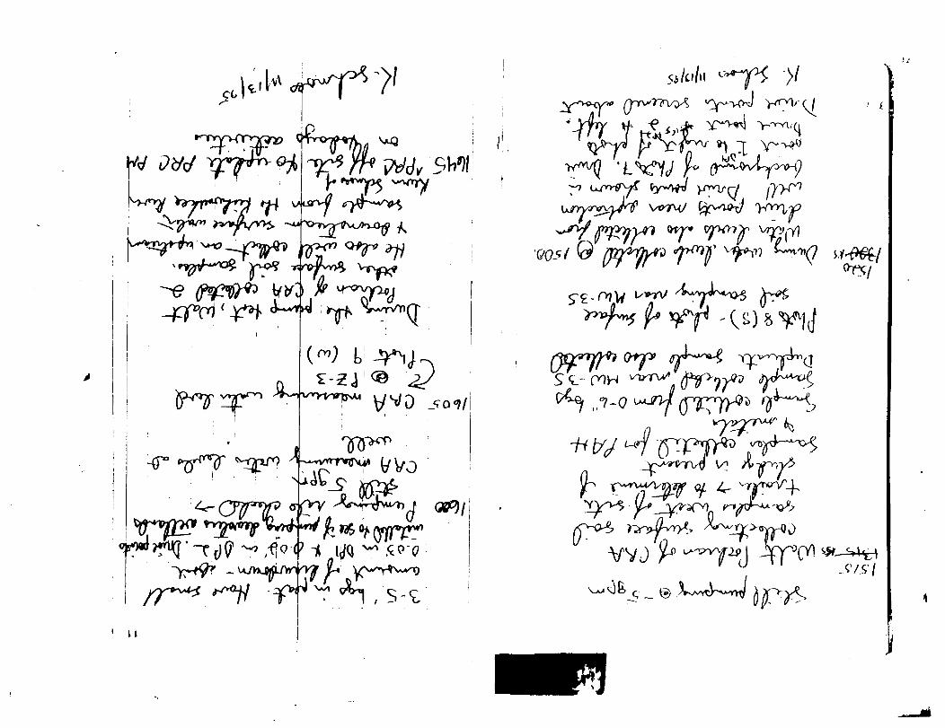
\_A^ ^ & c _ ®

r
/C (s> O/?/)

IWJ
I *
taf-
ajb:

.' 1
Loq^rpfa \#(f0-r^——<&t
5
(K>\\
A

LJW*^?
1)30
-> \jJ^-^Jf\ r^& AlAAjiM, ^My *?JA I , |
*s\£ yCA/za^v^V A^-^V ^^ ;4 A 'A-tSL^u-*^ i nV-*K AA^»\ !
J
AlXlfinHAM
c/j