
Field Oriented Control of a Three Phase Motor
12
Field Oriented Control of a Three Phase Motor Rod Bayliss III 12 December, 2018
Transcript of Field Oriented Control of a Three Phase Motor

Field Oriented Control of a Three Phase Motor
Rod Bayliss III
12 December, 2018

Contents
1 Overview 2
2 Field Oriented Control 32.1 3-phase transforms . . . . . . . . . . . . . . . . . . . . . . . . . . 32.2 Physical Interpretation . . . . . . . . . . . . . . . . . . . . . . . . 4
2.2.1 Field Weakening . . . . . . . . . . . . . . . . . . . . . . . 5
3 Controls 6
4 Implementation 8
5 Bugs and Challenges 9
6 Conclusion 11
1

Chapter 1
Overview
As a member of the FSAE Electric Racecar team I’ve found a fascination forelectric motors and the power electronics that drives them. Motor drive is areally cool intersection of mechanical design, magnetics, thermals, controls, andpower electronics. One of the most prevalent control algorithms for drivingthese three phase motors is called Field Oriented Control which aims to controlthe current vectors going into the motor to eventually achieve maximum torqueper amp delivered from the battery to the motor.
Figure 1.1: Schematic of Three phase inverter
2

Chapter 2
Field Oriented Control
2.1 3-phase transforms
One of the fundamentals of Field Oriented control is to transform complicated,time-varying three phase sinusoids into simplified control variables that con-veniently also have a physical implication. From a controls perspective these
Figure 2.1: Three phase graph
time-varying sinusoids are really hard to deal with and set clear controls vari-ables for. However, through the clarke and park transforms, the sinusoids turninto constant vectors which have important physical connections. By summingeach of these vectors, the result is a vector of constant length that spins at thefrequency of the original sinusoids. This is called the clarke trnsformation andputs us in the α − β frame. This frame has a single rotating vector with astationary reference frame. With the park transform (dq0), the reference frame
3

now spins with the current vector such that the vector appears stationary, giv-ing us DC terms to control, Id and Iq.
Figure 2.2: Illustration of transitioning from α− β frame to d− q frame.
Now that we can translate our currents into something easier to control theFOC process looks like sample my current sense ADCs, transform from abc todq0 and then do some control math.
2.2 Physical Interpretation
One of the reasons these transforms make so much sense and are so useful isbecause of the way they relate to the motor itself. I’ll limit this discussion tosurface permanent magnet motors as they’re simpler than IPMs when discussingmaximum torque per amp and field weakening. As this figure shows, the direct
Figure 2.3: Schematic of a surface PM motor with d and q axis illustrated
axis (d for short) aligns with the rotor permanent magnet while the quadratureaxis is halfway between the poles of the magnet (for a 2 pole motor that an-gle is 90◦, for a 4 pole it’s 45◦ etc.). When current flows exclusively on the d
4
axis, all the magnetic force generated also appears on that axis and as a result,no torque is produced. In contrast, if I put all of the current on the q-axis I getmax torque per amp as none of the current I put into the motor ends up on thed-axis aligned with the poles of the motor. Thus my objective with designingan effective inverter is placing all of my current on the q-axis and none on thed-axis to maximuize torque per amp (a common desire for a racecar application).
2.2.1 Field Weakening
However, current on the d-axis isn’t completely useless. Motors in electric vehi-cles often find themselves connected to high gear ratios to reduce the amount ofstall torque and current that appear frequently for cars stopping and going inthe city. Once the car reaches highway speeds though, the battery may run outof volts since the back-emf voltage is proportional to the speed of the motor.One solution to this is to put current on the negative d-axis, to oppose themagnetic fields generated by the permanent magnetics. Field weakening actsas a sort of transformer where, by putting energy into the system, you increasethe speed the motor can spin but equivalently reduce the torque it can produce.This reduces the motor’s efficiency as you’re putting in energy and not gettingan increase and power which is why IPMs are attractive as current on theird-axis does produce useful torque.
5

Chapter 3
Controls
Now that we know what to control and the next question is how to kick thesystem and develop a complete system. At a first order, by PWM’ing the halfbridges on each of the phases we can generate a sine wave with the average ofeach period (which the motor gives us for free since it’s an inductive load).
Figure 3.1: Illustration of using PWM to trace a sine wave
Figure 3.2: Example of 3-phases of center-aligned PWS
So our controls has to read in the currents going into the motor (our control
6
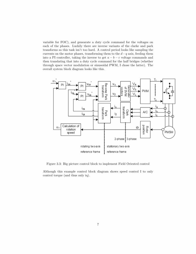
variable for FOC), and genearate a duty cycle command for the voltages oneach of the phases. Luckily there are inverse variants of the clarke and parktransforms so this task isn’t too hard. A control period looks like sampling thecurrents on the motor phases, transforming them to the d−q axis, feeding theminto a PI controller, taking the inverse to get a − b − c voltage commands andthen translating that into a duty cycle command for the half bridges (whetherthrough space vector modulation or sinusoidal PWM, I chose the latter). Theoverall system block diagram looks like this.
Figure 3.3: Big picture control block to implement Field Oriented control
Although this example control block diagram shows speed control I to onlycontrol torque (and thus only iq).
7

Chapter 4
Implementation
To create my motor controller I used an STM32F413 microcontroller (the samechip we use on our car). I paired this with a motor controller shield also bySTMicro whic gave me half bridges (STM L6230), current-sense resistors andamplifiers, and an encoder connection. I used a prop-drive sinusoidal SPMmotor set up on a jig lent to me by some MITERS friends. Fully set-up thesystem looks like this:
Every switching period (which ended up at around 5 kHz), I sampled my ADC(which was multiplexed over multiple channel which turned out to be a problem),transformed my currents from the abc frame to the d − q frame, fed them intomy PI block, inverse transformed from d− q to abc then scaled and shifted thatresulting control variable so it was centered around 50 (for 50% duty cycle) andranged from about 20% to 80%. The STM uses one Timer dedicated for PWMgeneration and interrupting every switching period and a second to decode theencoder.
8

Chapter 5
Bugs and Challenges
This system was full of lots of bugs that I had to fix to get it working so hereare some of the most impactful ones. First, one of the strangest modificationsI had to add to my motor was the series inductance. The half-bridge IC has apretty low curret-limit (≈ 2 A) which caused my phases to go low in the middleof the switching cycle. This led to some pretty strange behaviour but adding
the series inductance reduced the current into the motor and helped stabilizedits performance.One thing I grappled a lot with was getting the ADCs to perform well. TheSTM has three modes, polling, interrupt, and DMA, to interface with its ADCsand the mode I spent the most time fighting (polling) with would not work withwhat I intended to use it for. After finding this information in the corner ofa datasheet I switched modes and was able to get the adcs to feedback on mycurrents up and running.
9

Another register for the timer also lead to some bugs where my timer interruptwould trigger in the middle of a period, updating the register that set the dutycycle in the middle of a switching period, also creating un-desirable behaviour.Lastly I initially did not enable the PLLs on the chip, operating at a much lowerclock frequency than maximum (100 MHz). This caused my ISRs to take reallylong and not finish before the next switching period, causing more problems.
10

Chapter 6
Conclusion
Motor control is a very intriguing space because it’s vital to the performanceof EVs and is a hard problem to solve, especially when running at high RPMs.By driving the power electronics effectively, we can reduce the size and increasethe efficiency of our cars and get as much out of them as possible. Through twosmart transforms, we turn complicated AC waveforms into constant vectors thatare much easier to understand and control in the PID world and have importantphysical implications for motors.
11


