Field Experiments on Wave Propagation and Vibration ...cdn.intechweb.org/pdfs/6485.pdf · Field...
20
27 Field Experiments on Wave Propagation and Vibration Isolation by Using Wave Barriers Seyhan Fırat 1 , Erkan Çelebi 2 , Günay Beyhan 3 , İlyas Çankaya 4 , Osman Kırtel 2 and İsa Vural 1 1 Sakarya University, Technical Education Faculty, Construction Department 2 Sakarya University, Engineering Faculty, Civil Engineering Department 3 Sakarya University, Engineering Faculty, Geophysical Engineering Department 4 Sakarya University, Technical Education Faculty, Electronics and Computer Department Turkey 1. Introduction In most cases the major part of the vibration energy induced by dynamic sources transferred by the Rayleigh waves propagating in the region nearby soil surface may cause strong ground motions and stress levels that transmit the vibrations through the subsoil to the structures. Therefore, the permanent adversely effects of these excessive vibrations on the foundations, particularly supported on the soft soil deposits, cause structural damage to the adjacent structures. These vibrations give even disturbances to the nearby housing, sensitive electronic equipment, measuring installations and undesired actions on human comfort in the buildings. This type of vibrations in the frequency range from about 4-50 Hz may cause some structures to resonance with their vertical modes [1-2]. For an effective protection of the buildings from structural damage due to dynamic loads generated by man-made activities, such as rock drilling and blasting in road construction, working engine foundations in industrial areas, heavy and dense transport traffics due to increasing interconnections of residential regions etc., there are many possibilities to be considered as vibration screening systems. Especially, the development in passenger transport with high speed and the increased weight of high speed trains will cause strong ground and structural vibrations at the load path and in its neighborhood, particularly in intensively populated urban areas [3-4]. The special attention to this subject from the field of civil and railway engineering in association with the design of the railway track structures originates an increasing interest in methods, which can be classified as numerical, analytical or semi-empirical approaches for isolating vibrations. Published literature reveals several analytical studies [5-8] and some numerical models taking advances of both finite and boundary element approaches combined with analytical solutions for analysis of wave propagation problems in elastic medium with emphasis on soil-structure interaction due to moving loads [9-16]. The reduction of the structural response may be accomplished as: a) by adjusting the frequency contents of the excitation, b) by changing the location and direction of the vibratory source, c) by modifying the wave dissipation characteristics of the soil deposit, Source: Wave Propagation in Materials for Modern Applications, Book edited by: Andrey Petrin, ISBN 978-953-7619-65-7, pp. 526, January 2010, INTECH, Croatia, downloaded from SCIYO.COM www.intechopen.com
Transcript of Field Experiments on Wave Propagation and Vibration ...cdn.intechweb.org/pdfs/6485.pdf · Field...

27
Field Experiments on Wave Propagation and Vibration Isolation by Using Wave Barriers
Seyhan Fırat1, Erkan Çelebi2, Günay Beyhan3, İlyas Çankaya4, Osman Kırtel2 and İsa Vural1
1Sakarya University, Technical Education Faculty, Construction Department 2Sakarya University, Engineering Faculty, Civil Engineering Department
3Sakarya University, Engineering Faculty, Geophysical Engineering Department 4Sakarya University, Technical Education Faculty, Electronics and Computer Department
Turkey
1. Introduction
In most cases the major part of the vibration energy induced by dynamic sources transferred by the Rayleigh waves propagating in the region nearby soil surface may cause strong ground motions and stress levels that transmit the vibrations through the subsoil to the structures. Therefore, the permanent adversely effects of these excessive vibrations on the foundations, particularly supported on the soft soil deposits, cause structural damage to the adjacent structures. These vibrations give even disturbances to the nearby housing, sensitive electronic equipment, measuring installations and undesired actions on human comfort in the buildings. This type of vibrations in the frequency range from about 4-50 Hz may cause some structures to resonance with their vertical modes [1-2]. For an effective protection of the buildings from structural damage due to dynamic loads generated by man-made activities, such as rock drilling and blasting in road construction, working engine foundations in industrial areas, heavy and dense transport traffics due to increasing interconnections of residential regions etc., there are many possibilities to be considered as vibration screening systems. Especially, the development in passenger transport with high speed and the increased weight of high speed trains will cause strong ground and structural vibrations at the load path and in its neighborhood, particularly in intensively populated urban areas [3-4]. The special attention to this subject from the field of civil and railway engineering in association with the design of the railway track structures originates an increasing interest in methods, which can be classified as numerical, analytical or semi-empirical approaches for isolating vibrations. Published literature reveals several analytical studies [5-8] and some numerical models taking advances of both finite and boundary element approaches combined with analytical solutions for analysis of wave propagation problems in elastic medium with emphasis on soil-structure interaction due to moving loads [9-16]. The reduction of the structural response may be accomplished as: a) by adjusting the frequency contents of the excitation, b) by changing the location and direction of the vibratory source, c) by modifying the wave dissipation characteristics of the soil deposit,
Source: Wave Propagation in Materials for Modern Applications, Book edited by: Andrey Petrin, ISBN 978-953-7619-65-7, pp. 526, January 2010, INTECH, Croatia, downloaded from SCIYO.COM
www.intechopen.com
Wave Propagation in Materials for Modern Applications
510
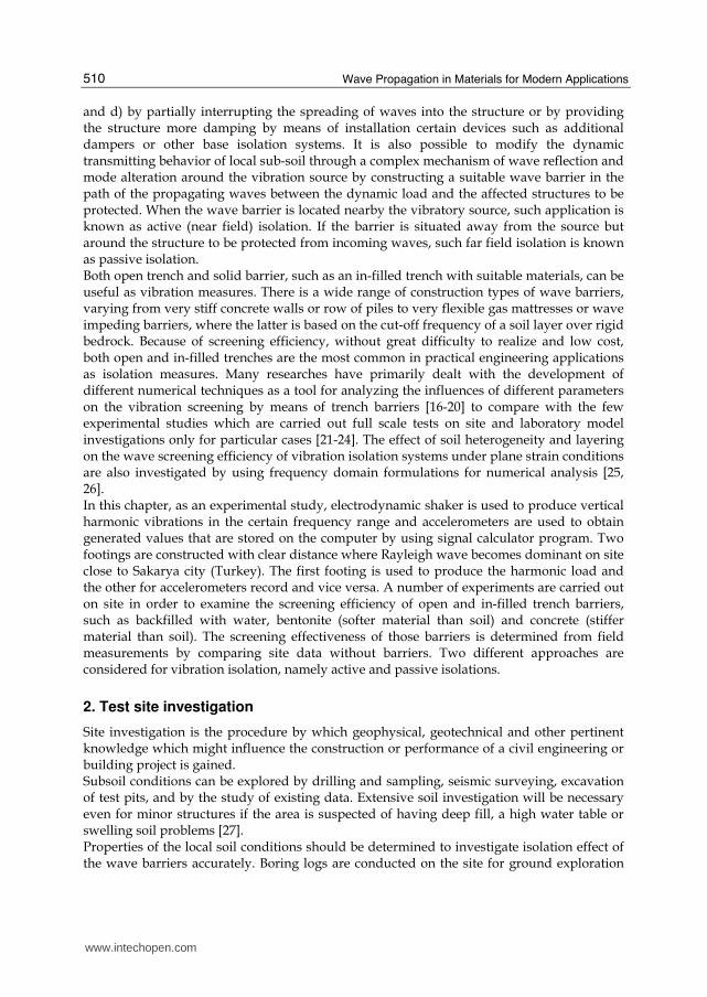
and d) by partially interrupting the spreading of waves into the structure or by providing the structure more damping by means of installation certain devices such as additional dampers or other base isolation systems. It is also possible to modify the dynamic transmitting behavior of local sub-soil through a complex mechanism of wave reflection and mode alteration around the vibration source by constructing a suitable wave barrier in the path of the propagating waves between the dynamic load and the affected structures to be protected. When the wave barrier is located nearby the vibratory source, such application is known as active (near field) isolation. If the barrier is situated away from the source but around the structure to be protected from incoming waves, such far field isolation is known as passive isolation. Both open trench and solid barrier, such as an in-filled trench with suitable materials, can be useful as vibration measures. There is a wide range of construction types of wave barriers, varying from very stiff concrete walls or row of piles to very flexible gas mattresses or wave impeding barriers, where the latter is based on the cut-off frequency of a soil layer over rigid bedrock. Because of screening efficiency, without great difficulty to realize and low cost, both open and in-filled trenches are the most common in practical engineering applications as isolation measures. Many researches have primarily dealt with the development of different numerical techniques as a tool for analyzing the influences of different parameters on the vibration screening by means of trench barriers [16-20] to compare with the few experimental studies which are carried out full scale tests on site and laboratory model investigations only for particular cases [21-24]. The effect of soil heterogeneity and layering on the wave screening efficiency of vibration isolation systems under plane strain conditions are also investigated by using frequency domain formulations for numerical analysis [25, 26]. In this chapter, as an experimental study, electrodynamic shaker is used to produce vertical harmonic vibrations in the certain frequency range and accelerometers are used to obtain generated values that are stored on the computer by using signal calculator program. Two footings are constructed with clear distance where Rayleigh wave becomes dominant on site close to Sakarya city (Turkey). The first footing is used to produce the harmonic load and the other for accelerometers record and vice versa. A number of experiments are carried out on site in order to examine the screening efficiency of open and in-filled trench barriers, such as backfilled with water, bentonite (softer material than soil) and concrete (stiffer material than soil). The screening effectiveness of those barriers is determined from field measurements by comparing site data without barriers. Two different approaches are considered for vibration isolation, namely active and passive isolations.
2. Test site investigation
Site investigation is the procedure by which geophysical, geotechnical and other pertinent knowledge which might influence the construction or performance of a civil engineering or building project is gained. Subsoil conditions can be explored by drilling and sampling, seismic surveying, excavation of test pits, and by the study of existing data. Extensive soil investigation will be necessary even for minor structures if the area is suspected of having deep fill, a high water table or swelling soil problems [27]. Properties of the local soil conditions should be determined to investigate isolation effect of the wave barriers accurately. Boring logs are conducted on the site for ground exploration
www.intechopen.com
Field Experiments on Wave Propagation and Vibration Isolation by Using Wave Barriers
511
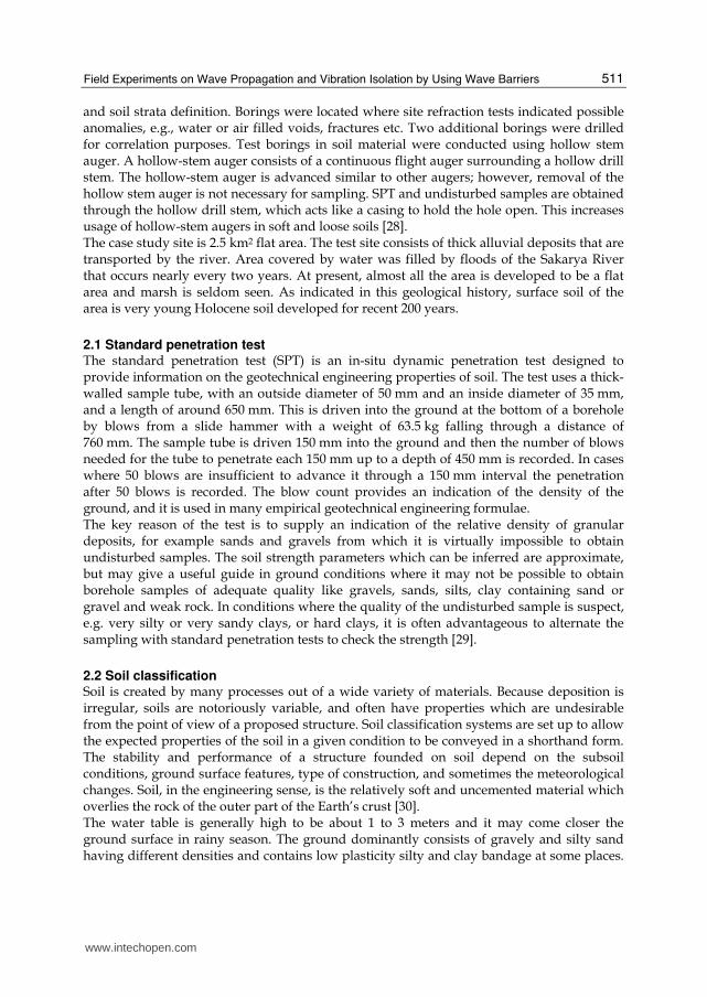
and soil strata definition. Borings were located where site refraction tests indicated possible anomalies, e.g., water or air filled voids, fractures etc. Two additional borings were drilled for correlation purposes. Test borings in soil material were conducted using hollow stem auger. A hollow-stem auger consists of a continuous flight auger surrounding a hollow drill stem. The hollow-stem auger is advanced similar to other augers; however, removal of the hollow stem auger is not necessary for sampling. SPT and undisturbed samples are obtained through the hollow drill stem, which acts like a casing to hold the hole open. This increases usage of hollow-stem augers in soft and loose soils [28]. The case study site is 2.5 km2 flat area. The test site consists of thick alluvial deposits that are transported by the river. Area covered by water was filled by floods of the Sakarya River that occurs nearly every two years. At present, almost all the area is developed to be a flat area and marsh is seldom seen. As indicated in this geological history, surface soil of the area is very young Holocene soil developed for recent 200 years.
2.1 Standard penetration test The standard penetration test (SPT) is an in-situ dynamic penetration test designed to provide information on the geotechnical engineering properties of soil. The test uses a thick-walled sample tube, with an outside diameter of 50 mm and an inside diameter of 35 mm, and a length of around 650 mm. This is driven into the ground at the bottom of a borehole by blows from a slide hammer with a weight of 63.5 kg falling through a distance of 760 mm. The sample tube is driven 150 mm into the ground and then the number of blows needed for the tube to penetrate each 150 mm up to a depth of 450 mm is recorded. In cases where 50 blows are insufficient to advance it through a 150 mm interval the penetration after 50 blows is recorded. The blow count provides an indication of the density of the ground, and it is used in many empirical geotechnical engineering formulae. The key reason of the test is to supply an indication of the relative density of granular deposits, for example sands and gravels from which it is virtually impossible to obtain undisturbed samples. The soil strength parameters which can be inferred are approximate, but may give a useful guide in ground conditions where it may not be possible to obtain borehole samples of adequate quality like gravels, sands, silts, clay containing sand or gravel and weak rock. In conditions where the quality of the undisturbed sample is suspect, e.g. very silty or very sandy clays, or hard clays, it is often advantageous to alternate the sampling with standard penetration tests to check the strength [29].
2.2 Soil classification Soil is created by many processes out of a wide variety of materials. Because deposition is irregular, soils are notoriously variable, and often have properties which are undesirable from the point of view of a proposed structure. Soil classification systems are set up to allow the expected properties of the soil in a given condition to be conveyed in a shorthand form. The stability and performance of a structure founded on soil depend on the subsoil conditions, ground surface features, type of construction, and sometimes the meteorological changes. Soil, in the engineering sense, is the relatively soft and uncemented material which overlies the rock of the outer part of the Earth’s crust [30]. The water table is generally high to be about 1 to 3 meters and it may come closer the ground surface in rainy season. The ground dominantly consists of gravely and silty sand having different densities and contains low plasticity silty and clay bandage at some places.
www.intechopen.com

Wave Propagation in Materials for Modern Applications
512
Site soils are characterized as clay, silty clays, silty gravel and gravel. Material properties of the test site are given in Table 1.
SUMMARY OF TESTING RESULTS
Report No: 06/0327 Sieve Atterberg
Analysis Limits Hydrometer
Project Name Soil Structure Profile
+ #
4
- #
20
0
LL PL PI
Soil Classification
Wa
ter
con
ten
t
-0,0
76
-0,0
05
Hole No Specimen No Depth (m) % % % % % TS1500 % % %
SK1 SPT 1 1.00-1.45 0 98 42 22 20 CI 32 98 46
SPT2 2.00-2.45 0 87 27 20 7 CL 32 87 18
UD1 2.50-3.00 0 85 26 20 6 CL 32 85 16
SPT 3 3.00-3.45 50 21 NPNPNP GM 9
SPT 4 4.50-4.95 59 5 NPNPNP GW-GM 7
SPT 5 6.00-6.45 0 84 28 22 6 CL 26 84 14
SPT 6 7.50-7.95 46 6 NPNPNP GW-GM 12
SPT 7 9.00-9.45 62 5 NPNPNP GW-GM 7
SPT 8 10.00-10.45 91 1 NPNPNP GW 4
SK2 SPT1 1.50-1.95 0 98 39 21 18 CI 28
UD1 2.50-3.00 0 95 40 21 19 CI 35
SPT2 3.00-3.45 0 93 38 22 16 CI 33
SPT3 4.50-4.95 54 5 NPNPNP GW-GM 9
SPT4 6.00-6.45 0 88 28 21 7 CL 37 88 18
SPT5 7.50-7.95 47 21 NPNPNP GM 14
SPT6 9.00-9.45 81 6 NPNPNP GW-GM 6
Table 1. Material properties of the test site.
2.3 Seismic refraction and reflection tests In reflection and refraction prospecting, body waves are the source of information used to image the Earth’s interior. In reflection experiments, analysis is concentrated on energy arriving after the initial ground motion. Specifically, the analysis concentrates on ground movement that has been reflected off of subsurface interfaces. Subsurface structures can be complex in shape but like the refraction methods are interpreted in terms of boundaries separating material with differing elastic parameters. Refraction experiments are based on the times of arrival of the initial ground movement generated by a source recorded at a variety of distances. Later arriving complications in the recorded ground motion are discarded. These are then interpreted in term of the depths to subsurface interfaces and the speeds at which motion travels through the subsurface within each layer. These speeds are controlled by a set of physical constants, called elastic parameters that describe the material [31]. In this study, thumper is used for both seismic refraction and reflection tests as an energy source. Soil dynamic parameters that are obtained by the tests are given in Table 2.
www.intechopen.com

Field Experiments on Wave Propagation and Vibration Isolation by Using Wave Barriers
513
Soil Dynamic Parameters
Parameters Symbol Unit 1. Layer 2. Layer 3. Layer 4. Layer
P (Compression) Wave Velocity
CP m/s 370 580 1012 1739
S (Shear) Wave Velocity CS m/s 133 220 341 570
Layer Thickness h m 0.7 1.2 1.8 2.3
Density ρ kN/m3 13.6 15.2 17.5 18.9
Maximum Shear Module Gmax kN/m2 23545 72098 199075 625615
Elasticity Module E kN/m2 67155 204174 571727 1319592
Poisson Ratio ν - 0.42 0.44 0.35 0.30
Soil Vibration Period T0 s 0.6
Table 2. Soil dynamic parameters in the test site.
3. Measurements for vibration screening performance
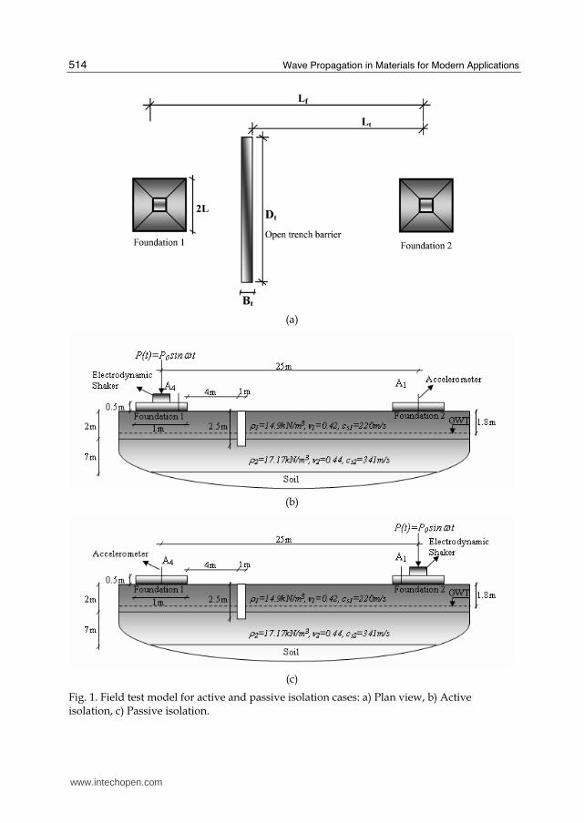
Evaluation of the screening effectiveness precisely depends on the barrier material stiffness. Hence, a series of experiments are necessary to understand the propagating characteristics of the waves. The test layout for both active and passive isolation cases is shown in Fig. 1. The layout consists of exciter, two concrete footing, wave barrier, and 2 measurement points. Electrodynamic shaker, which induces a sinusoidal motion, shown in Fig. 2 is used as a stationary vibration source to produce vertical harmonic force of maximum amplitude of 250 N in a frequency range of practical importance of 10 Hz to 95 Hz. Besides accelerometers are employed to obtain generated values that are stored on computer by
using signal calculator program. The excitation frequency is increased progressively in Δf = 5 Hz steps. The noise in the signals recorded during the test was eliminated during signal processing by digital filtering with a band-pass filter. The shaker is mounted on thin metal plate and placed centrically above the rigid square footing in order to excite only vertical vibrations. Two concrete surface footings with dimensions 1.0 m x 1.0 m x 0.5 m which are built on the site with clear distance of LF = 25 m are used. For research purposes, a rectangular, Dt = 3 m long open trench is constructed symmetrical about the center line between these footings. The first footing is used to produce the harmonic load and the other for accelerometers record and vice versa. The installed source on footing is placed at a distance of 4 m from the trench for the measurement of active isolation case and a distance of Lt = 20 m for measurement of passive isolation. The vertical components of harmonic vibrations are recorded with those
accelerometers located on these foundations, which corresponds to a time interval of Δt = 0.0005 sec. The displacement amplitudes are computed from the acceleration data. The screening performance of the material stiffness of the trench compared to soil and the excitation frequency range are investigated by conducting a series of field tests of source and receiver isolation barrier, namely active and passive vibration screens. The considered parameters are summarized in Table 3.
The length of Rayleigh (λR) wave of the generated vibration is one of the most critical factors to determine the screening effectiveness of wave barriers. Provided that the minimum depth
of open trench should be at least 0.6λR at a point 10λR away from such trench for active
isolation and 1.33λR for the passive when the measurement point is located at a distance
www.intechopen.com
Wave Propagation in Materials for Modern Applications
514
(a)
(b)
(c)
Fig. 1. Field test model for active and passive isolation cases: a) Plan view, b) Active isolation, c) Passive isolation.
www.intechopen.com

Field Experiments on Wave Propagation and Vibration Isolation by Using Wave Barriers
515
(a) (b)
(c) (d)
Fig. 2. Electrodynamic shaker and accelerometers placed on the foundations: a) Electrodynamic shaker placed on the foundation, b) Electrodynamic shaker and accelerometer, c) Measurements recorded foundation, d) Accelerometers placed on the foundation.
Material
Mass density,
ρ (t/m3)
Pressure wave
velocity, Cp (m/s)
Shear wave
velocity, Cs (m/s)
Poisson’s ratio, ν
Geometry
Depth of
trench, Ht (m)
Width of
trench, Bt (m)
Bentonite (softer) trench
1.65 400 100 0.35 Rectangular 2.5
1.0
Concrete (stiffer) barrier
2.40 5000 2400 0.20 Rectangular 2.5
1.0
Water filled
trench 0.98 - - 0 Rectangular 2.5
1.0
Table 3. Material properties and geometric parameters of the in-filled trench barrier.
between 2λR and 7λR from the wave barrier. The trench width has to be built between 0.1λR
and 0.5λR to accomplish such remarkable reduction in vertical soil vibrations [21-23]. The predominant values of the applied excitation frequencies in these experimental studies and the related Rayleigh wavelengths are given in Table 4 in order to determine the optimum
www.intechopen.com

Wave Propagation in Materials for Modern Applications
516
geometrical parameters of the rectangular trench barrier an average for an effective protection and to avoid the difficulties in their practical applications such as instability of soil, high water table levels, and high costs.
Active isolation
Passive isolation
Frequency of exciter
( f ) (Hz)
Wave length of Rayleigh
waves
(λR) (m)
Trench width, Bt
(min.0.1λR) (m)
Trench depth, Ht
(min.0.6λR) (m)
Measurement point from trench, Lt
(min.10λR ) (m)
Trench depth, Ht
(min.1.33λR)(m)
Measurement point from
trench
(min.2λR ) (m)
25 7.92 0.79 4.75 79.2 10.53 15.84 50 3.96 0.40 2.37 39.6 5.26 7.92 75 2.64 0.26 1.58 26.4 3.51 5.28
100 1.98 0.20 1.19 19.8 2.63 3.96 All All 1.00 2.50 20.0 2.50 5.00
Table 4. Rayleigh wavelength and minimum conditions for the screening effectiveness of an open trench barrier.
Four types of trench barriers are used to obtain better result of vibration control. For the case of in-filled trenches as shown in Fig. 3, the backfill material compared to soil is respectively considered as water, bentonite as softer material and concrete as stiffer material in place of the open trenches. For the sake of slope stability the trench walls are sealed by reinforced concrete in a width of 0.15 m. In the experimental program, A1 is denoted as observation point where foundation to be protected and A4 as excited foundation for active isolation case. A1 is donated as excited foundation and A4 to be protected foundation for passive isolation case.
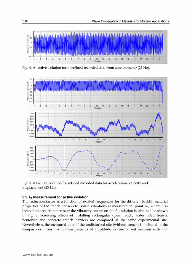
2.4 Data processing The data is obtained experimentally on the site, which is unrefined, for the case of active and passive isolations then refined by using SeismoSignal 3.02 programme which is defined as band-pass filtration (See Fig. 4 and 5). Then, the filtrated data is reproduced in Matlab environment to obtain the graphs. These obtained data for A1 and A4 recorded stations of displacement-time history graphs are figured out for all harmonic loadings and consequently for both active and passive cases (Fig. 6).
3.1 A1 measurement for active isolation The resulting time histories of the vertical response at point A1 for active isolation measures in the case of no trench, rectangular open trench and an in-filled trench are compared in Fig. 6. The wave propagation pattern of the transmitted vibrations in the case of both open and in-filled trench barriers is similar to the case of no trench. This general trend of the observed behavior changes only for an excitation frequency of 50 Hz. However, any time delay does not exist between the amplitudes of the spreading waves. The amplitude reduction factor Rf is defined as the vertical displacement amplitude after the presence of the trench barriers relative to the amplitude on the undisturbed site (without trench barriers). An effective screening exists when the calculated reduction factor from the experimental data is less than 0.6 for the applied excitation frequencies.
www.intechopen.com

Field Experiments on Wave Propagation and Vibration Isolation by Using Wave Barriers
517
(a) (b)
(c) (d)
Fig. 3. Trench barriers: a) Open trench, b) Water filled trench, c) Bentonite filled trench and d) Concrete filled trench.
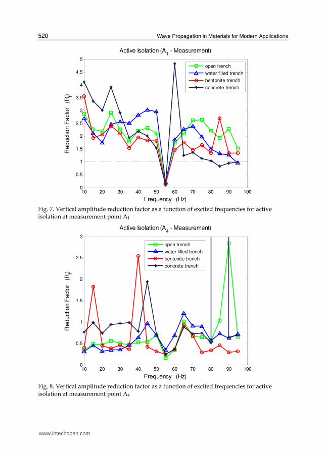
The amplitude reduction factor of vertical displacement due to harmonic sinusoidal load
with different frequencies applied for A1 measurements are shown in Fig. 7. At almost all
considered source frequencies the trench causes significantly amplification of the soil
vibration (Rf is greater than 1.0). The influence of the distance (Lt) between the measurement
point and the barrier location is significant for wave propagation. It should be over 10 times
the wavelength of Rayleigh wave (Lt = min10λR) for a considerable reduction in the vibration
level. In this study, the predominant values of applied excitation frequencies give Rayleigh
wavelengths λR to vary between 1.98 m and 7.92 m, which result in inadequate screening
(see Table 4). For insufficient distances (here, Lt = 20 m), strong wave interactions with wave
interference effects occur between the vibratory source and affected foundation to be protected.
www.intechopen.com
Wave Propagation in Materials for Modern Applications
518
Time [sec]
20191817161514131211109876543210
Accele
ratio
n [m
m/s
ec2]
1
0.5
0
-0.5
-1
-1.5
Fig. 4. A1 active isolation for unrefined recorded data from accelerometer (25 Hz).
Time [sec]
20191817161514131211109876543210
Accele
ratio
n [m
m/s
ec2]
0.2
0.1
0
-0.1
-0.2
-0.3
-0.4
-0.5
Time [sec]
20191817161514131211109876543210
Velo
city
[m
m/s
ec]
0.01
0.008
0.006
0.004
0.002
0
-0.002
-0.004
-0.006
Time [sec]
20191817161514131211109876543210
Dis
pla
cem
ent [m
m]
0.004
0.003
0.002
0.001
0
-0.001
-0.002
-0.003
-0.004
Fig. 5. A1 active isolation for refined recorded data for acceleration, velocity and displacement (25 Hz).
3.2 A4 measurement for active isolation The reduction factor as a function of excited frequencies for the different backfill material
properties of the trench barriers to isolate vibrations at measurement point A4, where it is
located an accelerometer near the vibratory source on the foundation is obtained as shown
in Fig. 8. Screening effects of installing rectangular open trench, water filled trench,
bentonite and concrete trench barriers are compared at the same experimental site.
Nevertheless, the measured data of the undisturbed site (without trench) is included in the
comparison. From in-situ measurements of amplitude in case of soil medium with and
www.intechopen.com

Field Experiments on Wave Propagation and Vibration Isolation by Using Wave Barriers
519
0 2 4 6 8 10 12 14 16-0.15
-0.1
-0.05
0
0.05
0.1
0.15
0.2
Time (sec)
Ve
rtic
al D
isp
lace
me
nt (m
m)
Active Isolation, f = 25 Hz (A1 - Measurement)
without trench
open trench
water filled trench
bentonite trench
concrete trench
0 2 4 6 8 10 12 14 16-0.15
-0.1
-0.05
0
0.05
0.1
0.15
0.2
Time (sec)
Ve
rtic
al D
ispla
ce
me
nt (m
m)
Active Isolation, f = 50 Hz (A1 - Measurement)
without trench
open trench
water filled trench
bentonite trench
concrete trench
0 2 4 6 8 10 12 14 16-0.15
-0.1
-0.05
0
0.05
0.1
0.15
0.2
Time (sec)
Ve
rtic
al D
ispla
ce
me
nt (m
m)
Active Isolation, f = 75 Hz (A1 - Measurement)
without trench
open trench
water filled trench
bentonite trench
concrete trench
Fig. 6. Comparison of the vertical displacement time histories at point A1 for active isolation measures due to three different frequencies of the exciter
www.intechopen.com
Wave Propagation in Materials for Modern Applications
520
10 20 30 40 50 60 70 80 90 1000
0.5
1
1.5
2
2.5
3
3.5
4
4.5
5
Frequency (Hz)
Re
du
ctio
n F
acto
r (R
f)
Active Isolation (A1 - Measurement)
open trench
water filled trench
bentonite trench
concrete trench
Fig. 7. Vertical amplitude reduction factor as a function of excited frequencies for active isolation at measurement point A1
10 20 30 40 50 60 70 80 90 1000
0.5
1
1.5
2
2.5
3
Frequency (Hz)
Re
du
ctio
n F
acto
r (R
f)
Active Isolation (A4 - Measurement)
open trench
water filled trench
bentonite trench
concrete trench
Fig. 8. Vertical amplitude reduction factor as a function of excited frequencies for active isolation at measurement point A4
www.intechopen.com
Field Experiments on Wave Propagation and Vibration Isolation by Using Wave Barriers
521
without any reduction measure, very effective vibration screening is observed for applied
frequencies. For both 10 and 25 Hz frequencies of exciter, water filled trench gives a good
isolation (Rf = 0.27) that achieve a reduction level up to 200% of the maximum vertical
displacements at observation time about t = 5 sec compared in case of subsoil without trench
barrier (Rf = 1.0). For these frequencies the isolation effect of bentonite and concrete trenches
follows that of the water filled trench, respectively. Because of the traveling a longer
propagation path surrounding the trench barrier, there is a certain time delay in the
incoming waves to the source. Bentonite trench barrier gives the best isolation measures in
high frequency values of 50, 75 and 95 Hz in Fig. 8. It reduces the maximum response
respect to the original site from 0.16 mm to 0.05 mm (Rf = 0.31) at about t = 5 sec for
excitation frequency of 50 Hz. Comparing the screening effects of bentonite trench with that
of the concrete barrier at 75 Hz, vibration isolation by bentonite trench is reduced the
maximum values about 2.5 times more than that of concrete barrier. The differences of the
screening efficiency depend on propagating wave characteristics which occur after hitting
an obstacle such as reflection, refraction and diffraction varied with the in-filled material
properties of the trench barriers.
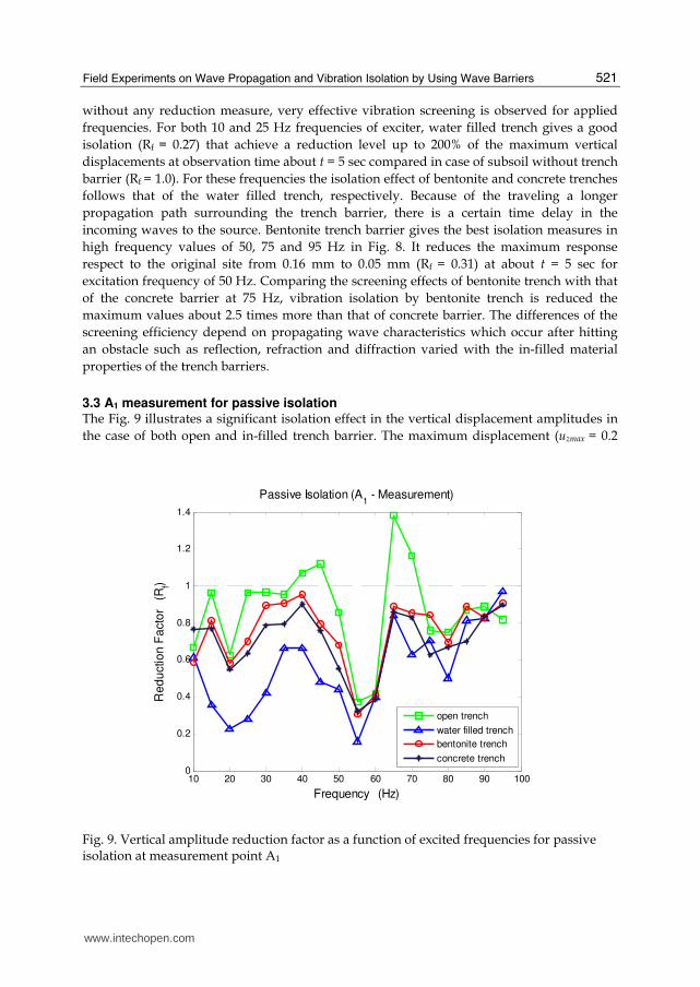
3.3 A1 measurement for passive isolation The Fig. 9 illustrates a significant isolation effect in the vertical displacement amplitudes in
the case of both open and in-filled trench barrier. The maximum displacement (uzmax = 0.2
10 20 30 40 50 60 70 80 90 1000
0.2
0.4
0.6
0.8
1
1.2
1.4
Frequency (Hz)
Re
du
ctio
n F
acto
r (R
f)
Passive Isolation (A1 - Measurement)
open trench
water filled trench
bentonite trench
concrete trench
Fig. 9. Vertical amplitude reduction factor as a function of excited frequencies for passive isolation at measurement point A1
www.intechopen.com

Wave Propagation in Materials for Modern Applications
522
mm) is obtained in the excitation frequency of 10 Hz with no trench case as expected (Rf =
1.0). It is observed that certain time delay occurs between the amplitudes of the spreading
waves. At all considered source frequencies, the trench barriers cause significantly reduction
of the soil vibrations (0 < t < 10 sec). Water filled trench gives the best screening effect (0.2<
Rf <0.6) in the range of the excitation frequencies from 10 Hz to 60 Hz. It reduces the
maximum vertical response from 0. 15 mm to 0.025 mm at t = 4 sec for applied frequency of
55 Hz. Concrete barrier, bentonite filled trench, open trench, and no trench follows in that
case. The displacement values are scattering in low frequency but the values are identical in
high frequency cases. Waves are traveling near the surface in high frequency. This causes to
be identical for all isolation measures.
3.4 A4 measurement for passive isolation In Fig. 10 the resulting time history on vertical displacements at measurement point A4 for
passive isolation is shown for the cases of subsoil without any reduction measure as well as
a trench barrier with various in-filled materials as reduction measures. The wave
propagation form of the transmitted vibrations in the case of both open and in-filled trench
barriers is almost similar to the case of no trench for low frequency values. When increasing
the frequency values of the stationary exciter the wave pattern becomes irregular due to soil
formations and complex mechanism of wave reflection varied with the in-filled material
properties of the trench barriers. Soil layers are more inhomogeneous near to the ground
surface. It is well known that waves penetrate to lower soil layers in low frequency values.
Bentonite filled trench barrier gives the best isolation effect in the frequency of 10 Hz. The
reduction efficiency of this trench barrier can reach around 40%. As shown in field test
results, the isolation effect of water filled trench is more effective for excitation frequency of
25 Hz. It reduces the maximum response respect to the undisturbed field from 0.038 mm to
0.0175 mm at about t = 5 sec. In high frequency values water and bentonite filled trenches
are effective. But in those cases waves are traveling near to surface and are named as noise
type of waves. Comparing the screening effects of bentonite barrier with that of the water
filled trench at 75 Hz of vibratory source, vibration isolation by water filled trench is
reduced the maximum values about 20% more than that of bentonite barrier. It is
anticipated that a softer material compared to soil is also performed as backfill material for
an in-filled trench barrier.
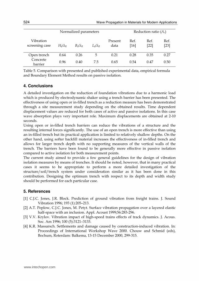
Table 5 compares the presented data with the empirical formula [23], numerical solutions
[16] and laboratory test results of Haupt [22]. For possible comparisons some values are
normalized as Ht/λR (Trench Depth/Rayleigh Wave), Bt/λR (Trench Width/Rayleigh Wave)
and Lt/λR (Distance from the Vibration Source/Rayleigh Wave) in terms of amplitude
reduction ratio Ar which is the ratio of the vertical displacement amplitudes at the point in
the presence and in the absence of the trench.
Wave characteristics such as reflection and diffraction at layer interfaces and the
heterogeneous nature of the soil play significant role on the results with the material
properties of the barrier especially for the experimental measurements. Also, it is not easy to
make available close results with published data due to the nature of the soil (water table
level, soil structure, layering effect, heterogeneity etc.).
www.intechopen.com

Field Experiments on Wave Propagation and Vibration Isolation by Using Wave Barriers
523
0 2 4 6 8 10 12 14 16-0.07
-0.05
-0.03
-0.01
0.01
0.03
0.05
0.07
Time (sec)
Ve
rtic
al D
isp
lace
me
nt (m
m)
Passive Isolation, f = 10 Hz (A4 - Measurement)
without trench
open trench
water filled trench
bentonite trench
concrete trench
0 2 4 6 8 10 12 14 16-0.07
-0.05
-0.03
-0.01
0.01
0.03
0.05
0.07
Time (sec)
Ve
rtic
al D
isp
lace
me
nt (m
m)
Passive Isolation, f = 25 Hz (A4 - Measurement)
without trench
open trench
water filled trench
bentonite trench
concrete trench
0 2 4 6 8 10 12 14 16-0.07
-0.05
-0.03
-0.01
0.01
0.03
0.05
0.07
Time (sec)
Ve
rtic
al D
isp
lace
me
nt (m
m)
Passive Isolation, f = 75 Hz (A4 - Measurement)
without trench
open trench
water filled trench
bentonite trench
concrete trench
Fig. 10. Comparison of the vertical displacement time histories at point A4 for passive isolation measures due to three different frequencies of the exciter
www.intechopen.com
Wave Propagation in Materials for Modern Applications
524
Normalized parameters Reduction ratio (Ar)
Vibration screening case
Ht/λR
Bt/λR
Lt/λR
Present
data
Ref. [16]
Ref. [22]
Ref. [23]
Open trench 0.64 0.26 5 0.21 0.28 0.35 0.27 Concrete barrier
0.96 0.40 7.5 0.65 0.54 0.47 0.50
Table 5. Comparison with presented and published experimental data, empirical formula and Boundary Element Method results on passive isolation.
4. Conclusions
A detailed investigation on the reduction of foundation vibrations due to a harmonic load which is produced by electrodynamic shaker using a trench barrier has been presented. The effectiveness of using open or in-filled trench as a reduction measure has been demonstrated through a site measurement study depending on the obtained results. Time dependent displacement values are reduced for both cases of active and passive isolations. In this case wave absorption plays very important role. Maximum displacements are obtained at 2-10 seconds. Using open or in-filled trench barriers can reduce the vibrations of a structure and the resulting internal forces significantly. The use of an open trench is more effective than using an in-filled trench but its practical application is limited to relatively shallow depths. On the other hand, using softer backfill material increases the effectiveness of in-filled trench and allows for larger trench depth with no supporting measures of the vertical walls of the trench. The barriers have been found to be generally more effective in passive isolation compared to active isolation for both measurement points. The current study aimed to provide a few general guidelines for the design of vibration isolation measures by means of trenches. It should be noted, however, that in many practical cases it seems to be appropriate to perform a more detailed investigation of the structure/soil/trench system under consideration similar as it has been done in this contribution. Designing the optimum trench with respect to its depth and width study should be performed for each particular case.
5. References
[1] C.J.C. Jones, J.R. Block. Prediction of ground vibration from freight trains. J. Sound Vibration 1996; 193 (1):205–213.
[2] A.T. Peplow, C.J.C. Jones, M. Petyt. Surface vibration propagation over a layered elastic half-space with an inclusion. Appl. Acoust 1999;56:283-296.
[3] V.V. Krylov. Vibration impact of high-speed trains effects of track dynamics. J. Acous. Soc. Am 1996; 100 (5):3121–3133.
[4] K.R. Massarsch. Settlements and damage caused by construction-induced vibration. In: Proceedings of International Workshop Wave 2000. Chouw and Schmid (eds), Bochum, Roterdam: Balkema, 13-15 December 2000, 299-315.
www.intechopen.com

Field Experiments on Wave Propagation and Vibration Isolation by Using Wave Barriers
525
[5] R.G. Payton. Transient motion of an elastic half-space due to a moving surface line load. International Journal of Engineering Sciences 1967; 5:49-79.
[6] E. Kausel. Thin-layer method. Int. J. Numer. Meth. Eng. 1994;37:927–941. [7] J.R. Barber. Surface displacements due to a steadily moving point force. J. Appl. Mech.
1996;63:245–251. [8] X. Sheng, C.J.C. Jones, M. Petyt. Ground vibration generated by a harmonic load acting
on a railway track. Journal of Sound and Vibration 1999;225 (1):3-28. [9] G. Schmid, B. Verbic. Modellierung der Erschütterung aus dem Schienenverkehr mit der
Randelelementmethode. In: H. Bachmann (Ed.), Erdbebensicherung bestehender Bauwerke und aktuelle Fragen der Baudynamik 1997; Tagungsband D-A-CH’97, SIA, Dokumentation DO145.
[10] M. Adam, G. Pflanz, G. Schmid. Two- and three-dimensional modeling of half-space and train-track embankment under dynamic loading. Soil Dyn. Earthquake Eng. 2000; 19 (8);559–573.
[11] B.Y. Yang, H.H. Hung. A 2.5D finite/infinite element approach for modeling visco-elastic bodies subjected to moving loads. Int. J. Numer. Meth. Eng. 2001; 240:1317–1336.
[12] C. Bode, R. Hirschauer, S.A. Savadis. Soil–structure interaction in the time domain using half-space Green’s functions. Soil Dyn. Earthquake Eng. 2002;22 (4):283–295.
[13] E. Celebi, G. Schmid. Investigation of ground vibrations induced by moving loads. Engineering Structures 2005;27:1981-1998.
[14] J.O’Brien, D.C. Rizos. A 3D BEM-FEM methodology for simulation of high speed train induced vibrations. Soil Dyn. Earthquake Eng. 2005;25:289-301.
[15] E. Celebi. Three-dimensional modeling of train-track and sub-soil analysis for surface vibrations due to moving loads. Applied Mathematics and Computation 2006; 79:209–230.
[16] D.E. Beskos, G. Dasgupta, I.G. Vardoulakis. Vibration isolation using open or filled trenches part 1: 2-D homogeneous soil. Comput. Mech. 1986;1 (1):43–63.
[17] R. Klein, H. Antes, D. Le Houedec. Efficient 3D modeling of vibration isolation by open trenches. Computers & Structures 1997;Vol. 64, No. 1-4:809-817.
[18] G. Pflanz, K. Hashimoto, N. Chouw. Reduction of structural vibrations induced by a moving load. J. Appl. Mech. 2002;5:555–563.
[19] M. Adam, O. von Estorff b. Reduction of train-induced building vibrations by using open and filled trenches. Computers and Structures 2005;83:11–24.
[20] E. Celebi, S. Fırat, I. Cankaya. The effectiveness of wave barriers on the dynamic stiffness coefficients of foundations using boundary element method. Applied Mathematics and Computation 2006;180:683–699.
[21] R.D. Woods. Screening of surface waves in soils. J. Soil Mech. Found. Eng. Div. ASCE 1968; 94 (4):951–979.
[22] W. A. Haupt. Model tests on screening of surface waves. In: Proceedings of the 10th International Conference on Soil Mech. Found. Eng., Stockholm, 1981, vol. 3, 215–222.
[23] S. Ahmad, T.M. Al-Hussaini. Simplified design for vibration screening by open and infilled trenches. Journal of Geotechnical Engineering 1991;117 (1):67-88.
[24] H. Antes, R. Klein, D. Le Houedec, J.P. Region. Validation in-situ de la theorie des barrieres de discontinuite dans le sol. In : Troisieme Colloque National, Genie
www.intechopen.com

Wave Propagation in Materials for Modern Applications
526
Parasismique et Aspects Vibratoires dans le Genie Civil, 1993, Paris, Association Francaise du Genie Parasismique.
[25] K. L. Leung, D.E. Beskos, I. G. Vardoulakis. Vibration isolation using open and infilled trenches. Part 3: 2-D non-homogenous soil. Computational Mechanics 1990;7:137-148.
[26] K. L. Leung, I. G. Vardoulakis, D.E. Beskos, J. L. Tassoulas. Vibration isolation by trenches in continuously non-homogenous soil by the BEM. Soil Dynamics and Earthquake Engineering 1991; Vol. 10(3):172-179.
[27] F. H. Chen. Soil Engineering and testing, Design and Remediation, CRC Press, 2000. [28] Soils and Foundations Handbook, State Materials Office, Gainesville, Florida, April
2004. [29] http://en.wikipedia.org/wiki/Standard_penetration_test [30] C. R. I. Clayton, M. C. Matthews and N. E. Simons. Soil Classification (Site
Investigation), Second Edition, Department of Civil Engineering, University of Surrey. [31] S. H. Danbom. Reflection Seismic Data Processing, Through the Looking Glass of Applied Exploration Geophysics, P.G. for Rice University ESCI 444, 2009.
www.intechopen.com

Wave Propagation in Materials for Modern ApplicationsEdited by Andrey Petrin
ISBN 978-953-7619-65-7Hard cover, 526 pagesPublisher InTechPublished online 01, January, 2010Published in print edition January, 2010
InTech Europe InTech China
In the recent decades, there has been a growing interest in micro- and nanotechnology. The advances innanotechnology give rise to new applications and new types of materials with unique electromagnetic andmechanical properties. This book is devoted to the modern methods in electrodynamics and acoustics, whichhave been developed to describe wave propagation in these modern materials and nanodevices. The bookconsists of original works of leading scientists in the field of wave propagation who produced new theoreticaland experimental methods in the research field and obtained new and important results. The first part of thebook consists of chapters with general mathematical methods and approaches to the problem of wavepropagation. A special attention is attracted to the advanced numerical methods fruitfully applied in the field ofwave propagation. The second part of the book is devoted to the problems of wave propagation in newlydeveloped metamaterials, micro- and nanostructures and porous media. In this part the interested reader willfind important and fundamental results on electromagnetic wave propagation in media with negative refractionindex and electromagnetic imaging in devices based on the materials. The third part of the book is devoted tothe problems of wave propagation in elastic and piezoelectric media. In the fourth part, the works on theproblems of wave propagation in plasma are collected. The fifth, sixth and seventh parts are devoted to theproblems of wave propagation in media with chemical reactions, in nonlinear and disperse media, respectively.And finally, in the eighth part of the book some experimental methods in wave propagations are considered. Itis necessary to emphasize that this book is not a textbook. It is important that the results combined in it aretaken “from the desks of researchers“. Therefore, I am sure that in this book the interested and activelyworking readers (scientists, engineers and students) will find many interesting results and new ideas.
How to referenceIn order to correctly reference this scholarly work, feel free to copy and paste the following:
Seyhan Fırat, Erkan Çelebi, Günay Beyhan, İlyas Çankaya, Osman Kırtel and İsa Vural (2010). FieldExperiments on Wave Propagation and Vibration Isolation by Using Wave Barriers, Wave Propagation inMaterials for Modern Applications, Andrey Petrin (Ed.), ISBN: 978-953-7619-65-7, InTech, Available from:http://www.intechopen.com/books/wave-propagation-in-materials-for-modern-applications/field-experiments-on-wave-propagation-and-vibration-isolation-by-using-wave-barriers
www.intechopen.com

University Campus STeP Ri Slavka Krautzeka 83/A 51000 Rijeka, Croatia Phone: +385 (51) 770 447 Fax: +385 (51) 686 166www.intechopen.com
Unit 405, Office Block, Hotel Equatorial Shanghai No.65, Yan An Road (West), Shanghai, 200040, China Phone: +86-21-62489820 Fax: +86-21-62489821