Field Assembly and Setup Guide - AndyMarkfiles.andymark.com/CascadeEffect_BuildGuide1.3.pdf ·...
20
AndyMark Field Components for 2014-2015 FIRST® Tech Challenge Field Assembly and Setup Guide Rev 1.3 1
Transcript of Field Assembly and Setup Guide - AndyMarkfiles.andymark.com/CascadeEffect_BuildGuide1.3.pdf ·...

AndyMark Field Components for 2014-2015 FIRST® Tech Challenge
Field Assembly and Setup Guide
Rev 1.3
1
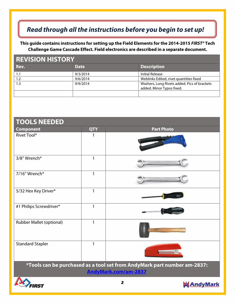
Read through all the instructions before you begin to set up!
This guide contains instructions for setting up the Field Elements for the 2014-2015 FIRST® Tech Challenge Game Cascade Effect. Field electronics are described in a separate document.
REVISION HISTORY Rev. Date Description
1.1 9/3/2014 Initial Release 1.2 9/6/2014 Weblinks Edited, rivet quantities fixed 1.3 9/9/2014 Washers, Long Rivets added. Pics of brackets
added. Minor Typos fixed.
TOOLS NEEDED Component QTY Part Photo Rivet Tool* 1
3/8” Wrench* 1
7/16” Wrench* 1
5/32 Hex Key Driver* 1
#1 Philips Screwdriver* 1
Rubber Mallet (optional) 1
Standard Stapler 1
*Tools can be purchased as a tool set from AndyMark part number am-2837: AndyMark.com/am-2837
2

RAMP/PLATFORM BUILD LIST Component QTY Part Photo Blue Ramp Panel 1
Red Ramp Panel 1
Blue Platform Panel 1
Red Platform Panel 1
Ramp Side Support 2
Ramp Rib 2
Folding Crate 2
Ramp Hardware 90° Bolt Bracket 12
15° Bracket 4
10-32 x 0.750 SHCS (Socket Head Cap Screw)
12
#10 Washers 12
10-32 Nylock Nut 12
Short Rivets (1/8” x 0.313-.375) 20
3
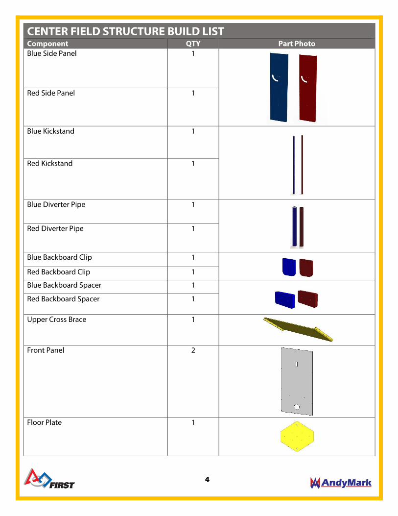
CENTER FIELD STRUCTURE BUILD LIST Component QTY Part Photo Blue Side Panel 1
Red Side Panel 1
Blue Kickstand 1
Red Kickstand 1
Blue Diverter Pipe 1
Red Diverter Pipe 1
Blue Backboard Clip 1
Red Backboard Clip 1
Blue Backboard Spacer 1
Red Backboard Spacer 1
Upper Cross Brace 1
Front Panel 2
Floor Plate 1
4

Splitter Ramp 1
Ball Tray 2
Center Pivot 1
275mm Goal Tube 2
Goal Backboard 2
275mm Measuring Tape Stickers 2
FTC Logo Sticker 2
Base Number Stickers 6
Center Goal Hardware Kit 90° Bracket 4
90° Bolt Bracket 6
Long Rivets (1/8”x.501-.625 long) 58
Rivet Washer 100
Center Pivot Bolt and nut 1
10-32 x 0.375 BHCS (Button Head Cap Screw)
6
10-32 x 1.000 SHCS (Socket Head Cap Screw)
4
10-32 x 1.250 (Socket Head Cap Screw) 2
10-32 Nylock Jam Nuts 14
5
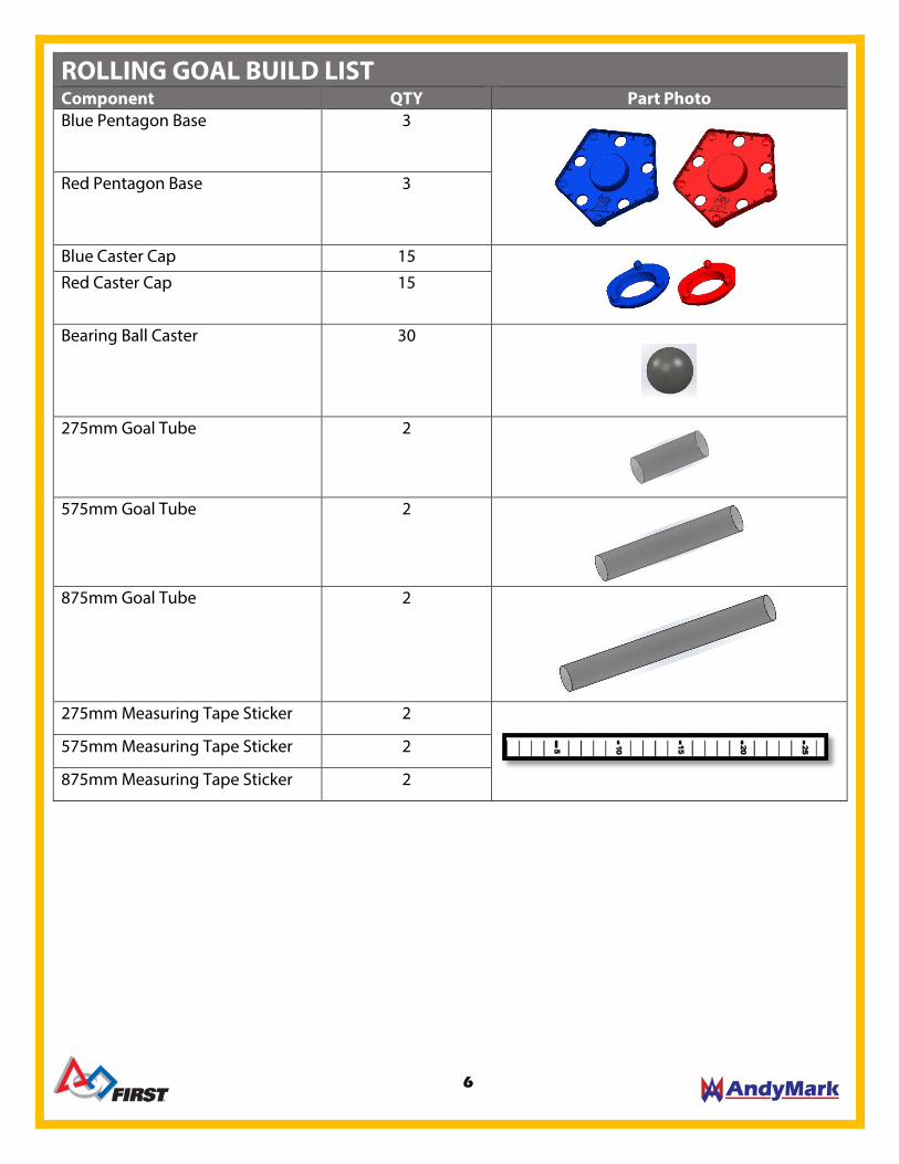
ROLLING GOAL BUILD LIST Component QTY Part Photo Blue Pentagon Base 3
Red Pentagon Base 3
Blue Caster Cap 15
Red Caster Cap 15
Bearing Ball Caster 30
275mm Goal Tube 2
575mm Goal Tube 2
875mm Goal Tube 2
275mm Measuring Tape Sticker 2
575mm Measuring Tape Sticker 2
875mm Measuring Tape Sticker 2
6
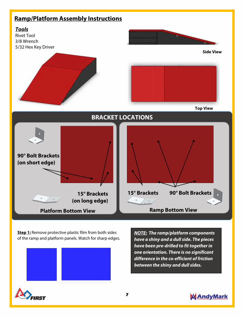
Ramp/Platform Assembly Instructions
Tools Rivet Tool 3/8 Wrench 5/32 Hex Key Driver
Ramp Bottom View Platform Bottom View
15° Brackets 90° Bolt Brackets
BRACKET LOCATIONS Top View
Side View
15° Brackets (on long edge)
90° Bolt Brackets (on short edge)
Step 1: Remove protective plastic film from both sides of the ramp and platform panels. Watch for sharp edges.
NOTE: The ramp/platform components have a shiny and a dull side. The pieces have been pre-drilled to fit together in one orientation. There is no significant difference in the co-efficient of friction between the shiny and dull sides.
7
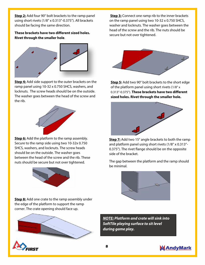
Step 2: Add four 90° bolt brackets to the ramp panel using short rivets (1/8" x 0.313”-0.375"). All brackets should be facing the same direction.
These brackets have two different sized holes. Rivet through the smaller hole.
Step 4: Add side support to the outer brackets on the ramp panel using 10-32 x 0.750 SHCS, washers, and locknuts. The screw heads should be on the outside. The washer goes between the head of the screw and the rib.
Step 3: Connect one ramp rib to the inner brackets on the ramp panel using two 10-32 x 0.750 SHCS, washer and locknuts. The washer goes between the head of the screw and the rib. The nuts should be secure but not over tightened.
Step 5: Add two 90° bolt brackets to the short edge of the platform panel using short rivets (1/8" x 0.313”-0.375"). These brackets have two different sized holes. Rivet through the smaller hole.
Step 6: Add the platform to the ramp assembly. Secure to the ramp side using two 10-32x 0.750 SHCS, washers, and locknuts. The screw heads should be on the outside. The washer goes between the head of the screw and the rib. These nuts should be secure but not over tightened.
Step 7: Add two 15° angle brackets to both the ramp and platform panel using short rivets (1/8" x 0.313”-0.375"). The rivet flange should be on the opposite side of the bracket.
The gap between the platform and the ramp should be minimal.
Step 8: Add one crate to the ramp assembly under the edge of the platform to support the ramp corner. The crate opening should face up.
NOTE: Platform and crate will sink into SoftTile playing surface to sit level during game play.
8
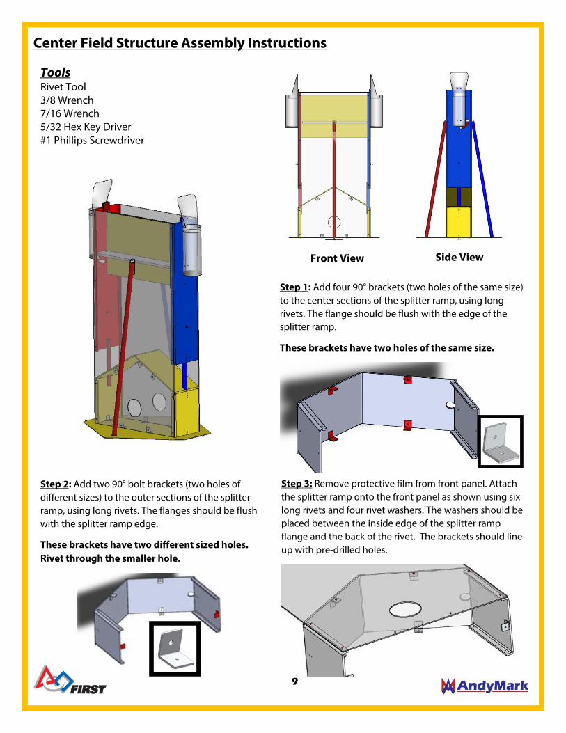
Center Field Structure Assembly Instructions
Step 1: Add four 90° brackets (two holes of the same size) to the center sections of the splitter ramp, using long rivets. The flange should be flush with the edge of the splitter ramp.
These brackets have two holes of the same size.
Step 2: Add two 90° bolt brackets (two holes of different sizes) to the outer sections of the splitter ramp, using long rivets. The flanges should be flush with the splitter ramp edge.
These brackets have two different sized holes. Rivet through the smaller hole.
Step 3: Remove protective film from front panel. Attach the splitter ramp onto the front panel as shown using six long rivets and four rivet washers. The washers should be placed between the inside edge of the splitter ramp flange and the back of the rivet. The brackets should line up with pre-drilled holes.
Tools Rivet Tool 3/8 Wrench 7/16 Wrench 5/32 Hex Key Driver #1 Phillips Screwdriver
Front View Side View
9

Step 4: Place one side red side panel and one blue side panel on the edge of the front panel. The flanges should face inside and the curved cutout should be oriented so it is furthest away from the splitter ramp.
Step 5: Using three long rivets and washers per side, attach the front panel to red side panel and the blue side panel through the pre-drilled holes. The washers should be placed between the inside flange and the back of the rivet.
Step 6: Add the upper cross brace to the side panels and secure with long rivets and washers on each side. The washers should be placed between the inside flange and the back of the rivet.
Step 7: Insert one red divider pipe into the splitter ramp on the red side and one blue divider pipe into the splitter ramp on the blue side. These pipes are a tight fit in the hole.
Step 8: Using six long rivets on each pipe attach the diverter pipes to the side panels and the ramp. The color should match the side panel.
Rivet Locations
Rivet Locations
NOTE: Insert all six rivets into the diverter pipe and center structure pre-drilled holes to align before riveting to panels to keep parts straight.
10

Step 9: Remove protective film and add a front panel to the goal assembly. The orientation should match the existing front panel. Secure with 12 long rivets and washers to side panels and splitter ramp. The washers should be placed between the inside flange and the back of the rivet.
Step 12: Add four 90° bolt brackets to the both front panels and ramp and secure using long rivets.
These brackets have two different sized holes. Rivet though the smaller hole.
Step 10: Place one ball tray into the assembly. The tongue should sit in the slot on the front panel.
Step 11: Two different length 10-32 screws are used to attach the ball tray. The longer 10-32 x 1.250” SHCS is used on the side where the upper cross brace flange is. The shorter 10-32 x1.000” SHCS is used on the side where there is no flange. These screws act as the pivot point for the ball tray. Be careful not to over-tighten screws.
Top view
Step 13: Remove protective plastic film. With the assembly upside-down secure the floor plate to the 90° bolt brackets using six 10-32 x 0.375 BHCS and 10-32 locknuts.
10-32 x 1.250” SHCS
10-32 x 1.000” SHCS
NOTE: Ball tray tongue will not be centered in the slot on the front panels.
NOTE: Be careful not to over-tighten screws.
11
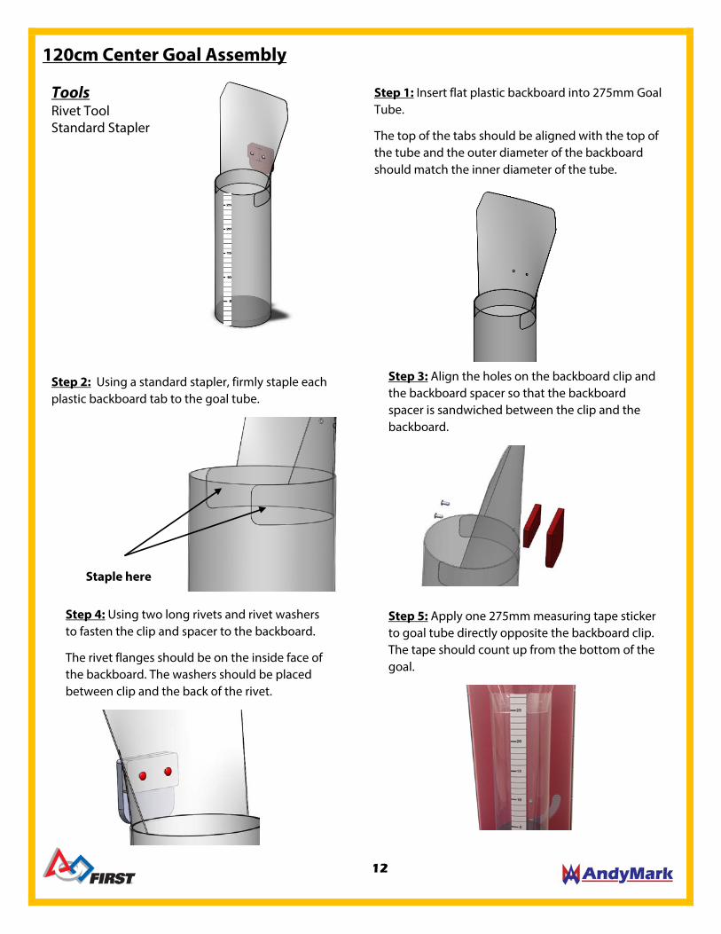
120cm Center Goal Assembly
Step 4: Using two long rivets and rivet washers to fasten the clip and spacer to the backboard.
The rivet flanges should be on the inside face of the backboard. The washers should be placed between clip and the back of the rivet.
Step 1: Insert flat plastic backboard into 275mm Goal Tube.
The top of the tabs should be aligned with the top of the tube and the outer diameter of the backboard should match the inner diameter of the tube.
Step 2: Using a standard stapler, firmly staple each plastic backboard tab to the goal tube.
Staple here
Step 3: Align the holes on the backboard clip and the backboard spacer so that the backboard spacer is sandwiched between the clip and the backboard.
Step 5: Apply one 275mm measuring tape sticker to goal tube directly opposite the backboard clip. The tape should count up from the bottom of the goal.
Tools Rivet Tool Standard Stapler
12
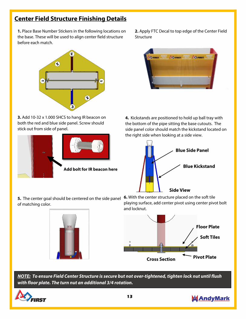
Center Field Structure Finishing Details
2. Apply FTC Decal to top edge of the Center Field Structure
3. Add 10-32 x 1.000 SHCS to hang IR beacon on both the red and blue side panel. Screw should stick out from side of panel.
Add bolt for IR beacon here
1. Place Base Number Stickers in the following locations on the base. These will be used to align center field structure before each match.
4. Kickstands are positioned to hold up ball tray with the bottom of the pipe sitting the base cutouts. The side panel color should match the kickstand located on the right side when looking at a side view.
6. With the center structure placed on the soft tile playing surface, add center pivot using center pivot bolt and locknut.
Floor Plate
Pivot Plate
Soft Tiles
Cross Section
NOTE: To ensure Field Center Structure is secure but not over-tightened, tighten lock nut until flush with floor plate. The turn nut an additional 3/4 rotation.
5. The center goal should be centered on the side panel of matching color.
Blue Side Panel
Blue Kickstand
Side View
13

Step 2: Secure the five bearing balls to the base by pressing in the caster caps until they’re flush with the base. This can be done by hand, or a rubber mallet may be used.
Rolling Goal Assembly
Step 1: Add five 1" Bearing Balls to the indents in the Red Pentagon Base.
Step 3: Apply the stick-on measuring tape to the outside of the goal tube. This can be
done by peeling the backing off, laying the label down on a flat surface and carefully
rolling the tube across the label.
Step 4: Insert the goal tube onto the base on the side opposite the casters. The numbers on the measuring tape should be right side up when the goal is sitting on the floor.
Tools Rubber Mallet (Optional)
NOTE: Assembly process is the same for all 3 Rolling Goal Sizes.
A red and blue goal of each size is used on the field.
14

FIELD REQUIREMENTS Component QTY Part Photo Source FTC Field Perimeter 1
AndyMark.com/am-481a
5/8” Gray Soft Tiles 36
AndyMark.com/Softtiles
IR Beacon (Either HBK2100 or FTCBCN)
2
http://www.hitechnic.com/
AndyMark.com/am-2978
Large Ball 40
AndyMark.com/am-2968full Small Ball 120
2” “Red” Gaffers Tape as
needed
http://www.findtape.com (pro gaff tape)
AndyMark.com/am-2967
2” “Electric Blue” Gaffers Tape
as needed
http://www.findtape.com (pro gaff tape)
AndyMark.com/am-2967
15

Center Field Structure 1
AndyMark.com/am-2835
Red Ramp/Platform 1
AndyMark.com/am-2836r
Blue Ramp/Platform 1
AndyMark.com/am-2836b
Red 30cm Rolling Goal 1
AndyMark.com/am-2832r
Red 60cm Rolling Goal 1
Red 90cm Rolling Goal 1
Blue 30cm Rolling Goal 1
AndyMark.com/am-2832b
Blue 60cm Rolling Goal 1
Blue 90cm Rolling Goal 1
All Official Field Elements can be found on http://www.andymark.com/FTC. DIY plans for wooden practice models are available for the Center Field Structure
and the Ramp/Platforms
16

NOTE: Lay the tiles out and mark the outer edge to be cut. Use a sharp box cutter and a straight edge or a band saw (if available) to get a smooth clean edge
Setting up the Floor and Field Perimeter
B
A
Critical Mandatory Step
C
C. Note that there are several FTC Playing Field wall designs. The wall designs fall into two categories:
1) symmetrical inside and outside surfaces; and 2) smooth on one side and an open cavity on the other side. The smooth/noncavity sides should face towards the inside of the Playing Field as shown in the illustration. If the wall has a cavity, it should be oriented so that it faces outside the Playing Field. Follow the set-up instructions supplied with your Field for details.
A. Lay the tiles with the smooth surface facing up.
B. Critical Mandatory Step: Trim all outer tabs from the Soft Tiles.
17

Ramp/Platform is placed in the corner of the field with the crate towards the field perimeter
Field Layout and Orientation
FCS STATION
AUDIENCE
90cm
30cm
60cm
Rolling Goals are centered in a tile, with the 90cm Rolling Goal in the corner, the 60cm Rolling Goal one tile towards the Alliance am, and the 30cm Rolling Goal one tile from the corner toward the opposing Alliance Parking Zone.
Tape dimensions measured to outside edge of tape. All tape is 2” wide.
Center Field Structure is located 3 tiles in from each edge in the center of the playing field floor. Center Pivot sits under tiles.
Tape Diagram and Field Element Placement
Parking zone tape follows inside edge of Soft Tile interlocking blocks
18
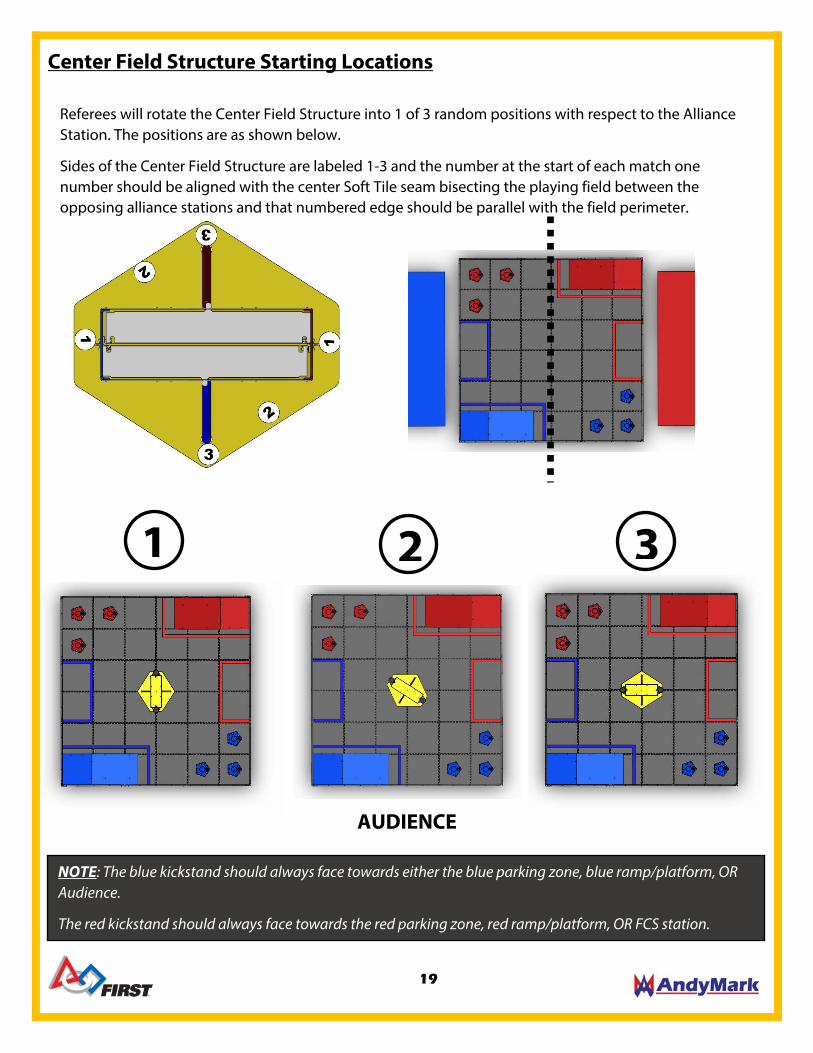
NOTE: The blue kickstand should always face towards either the blue parking zone, blue ramp/platform, OR Audience.
The red kickstand should always face towards the red parking zone, red ramp/platform, OR FCS station.
Center Field Structure Starting Locations
Referees will rotate the Center Field Structure into 1 of 3 random positions with respect to the Alliance Station. The positions are as shown below.
Sides of the Center Field Structure are labeled 1-3 and the number at the start of each match one number should be aligned with the center Soft Tile seam bisecting the playing field between the opposing alliance stations and that numbered edge should be parallel with the field perimeter.
1 2 3
AUDIENCE
19

IR Beacon Placement
NOTE: For this season’s game the four position switch should be set so the beacon is running in 1.2 KHz mode (the two leftmost positions). This is the same frequency mode that the older style beacons (#FTCBCN) use. You can run the beacon in either 180° (leftmost) or 360° mode (second from left). If you run your beacon in 180° mode, then make sure the active side of the beacon is facing outward towards the playing field (and away from the back of the wooden hanger). There are red LEDs on the printed circuit board of the new IR beacon. A lit red LED indicates that a side of the beacon is active. In 180° mode only one of the LEDs will be lit. In 360° mode both red LEDs will be lit.
Place one IR Beacon on each hanging bolt on both the red and blue side panels.
There are two styles of IR Beacons available for the 2014-2015 season. Note that you should use the same style of beacon per Field. Do not mix an older style beacon with a newer style beacon on the same Field. Either use all newer style beacons (HBK2100) or all older style beacons (FTCBCN) on a single Field
20