-Fidelity Amplif Phone - World Radio History
70
OHM'S LAW E =IXR R_ E = E R CONDENSERS IN SERIES CI X C2 Ci + C2 ' C TOTAL RESISTANCES IN PARALLEL RTOTAL = R1 X R2 Fit + R2 BOTTOM VIEWS OF SOCKETS 4 -PRONG SOCKET 50. 201 -A, 45, 210, 30, 31, ETC. S-PRLNb ct1 p56-46-47-76-27-R1 6 -PRONG SOCKET 2A5- 41.42.43 © CTM- OGE O' O V CRC -I.f,, (IP C,P 6 -PRONG SOCKET 57- 58.6C6- 606 -77 -78 7 -PRONG SOCKET 59 CROS N: iAN*5 GRID N :2 GPO N!I GRO 1424 -METAL TOO CAP 7 -PRONG SOCKET 2A7.4Á7 2 5 c Lin Cenede] JANUARY, 1935 $3.00 PER YEAR BY SUBSCRIPTION ESTABLISHED 1917 SHORT -WAVE AND EXPERIMENTAL -IN THIS ISSUE - The First Practical 5 -Meter Superheterodyne A Link -Coupled High- Frequency Receiver Complete Data on New RCA -802 Pentode High -Fidelity Audio Amplif :er Problems Hum -Free Pre -Amplifiers for Amateur Phone Mercury Vapor Rectifier Tube Considerations Frank C. Jones' 5 -Meter Superheterodyne -the First Workable Receiver of Its Kind. See Page 8. FEATURE ARTICLES BY .. . CLAYTON F. BANE FRANK C. JONES - COL. C. FOSTER J. N. A. HAWKINS - - FRANK LESTER - - I. A. MITCHELL Mar www.americanradiohistory.com
Transcript of -Fidelity Amplif Phone - World Radio History
OHM'S LAW E =IXR
R_ E
= E R
CONDENSERS IN SERIES
CI X C2 Ci + C2
' C TOTAL
RESISTANCES IN PARALLEL
RTOTAL = R1 X R2
Fit + R2
BOTTOM VIEWS OF SOCKETS
4 -PRONG SOCKET 50. 201 -A, 45, 210, 30, 31, ETC.
S-PRLNb ct1 p56-46-47-76-27-R1
6 -PRONG SOCKET 2A5- 41.42.43
© CTM- OGE
O' O V CRC -I.f,, (IP C,P
6 -PRONG SOCKET 57- 58.6C6- 606 -77 -78
7 -PRONG SOCKET 59
CROS N: iAN*5
GRID N :2
GPO N!I
GRO 1424 -METAL TOO CAP 7 -PRONG SOCKET
2A7.4Á7
2 5 c Lin Cenede] JANUARY, 1935 $3.00 PER YEAR
BY SUBSCRIPTION
ESTABLISHED 1917
SHORT -WAVE AND EXPERIMENTAL
-IN THIS ISSUE - The First Practical 5 -Meter Superheterodyne
A Link -Coupled High- Frequency Receiver Complete Data on New RCA -802 Pentode
High -Fidelity Audio Amplif :er Problems
Hum -Free Pre -Amplifiers for Amateur Phone Mercury Vapor Rectifier Tube Considerations
Frank C. Jones' 5 -Meter
Superheterodyne -the First Workable Receiver
of Its Kind. See Page 8.
FEATURE ARTICLES BY .. .
CLAYTON F. BANE FRANK C. JONES - COL. C. FOSTER J. N. A. HAWKINS - - FRANK LESTER - - I. A. MITCHELL
Mar www.americanradiohistory.com
a
"WE USE 'EM AND LIKE'EM "" ANODES
oc,,"' fte?
ó E Sc4 o+
0 4+
9, O``O aA` +
0
#1- `! 1
G.
Sylvania Type 212 -D
SP roet
e ctw 0 °Oyoy0Si0t
y1y ro °c e ,
.t't `c,,l a,° w°yeSc G°tó0o.
,ye 19Gc°t011 .0 '1.. y10 t .y 1, 0 4 oy 2°. r° t6 ..ye /..9
4t 00s;sç re e ,P
91s9 co1 ¢.e at c0t 4oS n%c t9, O O
6SeGto01,
S :1°°' o0ac 0e9°e4`4s°r1°be So4te°0 °°°st°°1
,S C,'
P se.á Osjo°1o0 e Osre o14 et{ ea Jeti°:ASeat
G b P y 'N'
°J'7 °4 [ g°' 0 ,. ,. t gy°c°Q`i tie, `<,ó0'c,.. Á1 y Ott`ey, vLv°riy0t,6 1K sy '
t0óa1 etc y
0rotirowyle eo°a ,,e°,11 °
O°0t 2 9
e aea y0 4
y^y1' ocroe e o° 4oea 1e41°Go°°J o0°°
° Zy e f °s st\A a4,°9 01' e0tir ,00 °locye s, y0owy1 SO ete°S°á R°a rott° e`' e o° e sy ro py t 0 0 .°0 009 yro
4°0,1 c aeo ,e .y00 Oeo, °ta° y 0 y5
.1.. . G c°° 4°S
.fi oroee0
t04 te J {aa sG00a ,et e.0áewo v0 c °F 4% ,.O. ,r+yti°ti 0 9 0
KA C,' 0o Os y0 á ó 0 st,y
VC .,09 ,y9 s
s e0 c,°0 e e0 a000a°ecy et0 0 c,e r o ay et G1 -(a ,,c c
c ,41C' 50011 e 0' croe 00 et St, "o`)' es' oS w .\,o yo .see, <;1` 0' c09> 0.4'.'C
C yro c 0c ye e ot
o1 c%s C1e°Fw °
0 .09.
009y0Q, Sec'OSye
01 ro00a
0c ct0 0S°tet0c
.y1009 Scro° t° áot° t9 .1 o4
0 ó°Ojoy0ó F°tets ayr
so ceros te ße e e 0
oJt Oo` 0s '0° Q ' r,9
t cJro w G
Sylvania Graphite Anode tubes are taking the country by storm. Broad- casters everywhere praise these tubes for their stability and long service life.
The engineers at Hygrade Sylvania Cor- poration's Clifton plant developed, and were the first to successfully produce GRAPHITE ANODE tubes. There is no doubt in the mind of the keen, up to the minute broadcaster that these
tubes are definitely super- ior to other tubes.
Prove to yourself the economy resulting from the extra long service
life of Sylvania Graphite Anode types, by specifying the purchase of Sylvania tubes in
your next tube order! The type 212 -D has gone over big! The letter
above tells the story. Can we say more? (0' i934, HSC
HYGRADE SYLVANIA CORPORATION Hygrade Lamps ELECTRONICS DEPARTMENT, CLIFTON, N. J. Sylvania Tubes FACTORIES: SALEM, MASS. EMPORIUM, PA. ST. MARYS, PA. CLIFTON, N. J.
WAREHOUSE STOCKS IN: Portland, Ore., Atlanta, Ga., Denver, Col.; Chicago, Ill.; Salem, Massa Dallas, Texas, Philadelphia, Pa., Pittsburgh, Pa., Los Angeles, Cal.
2 RADIO FOR JANUARY
1
www.americanradiohistory.com
r HAMMARLUND
CHOKES are BETTER in Design,
Mechanical Construction, Electrical Features
BETTER
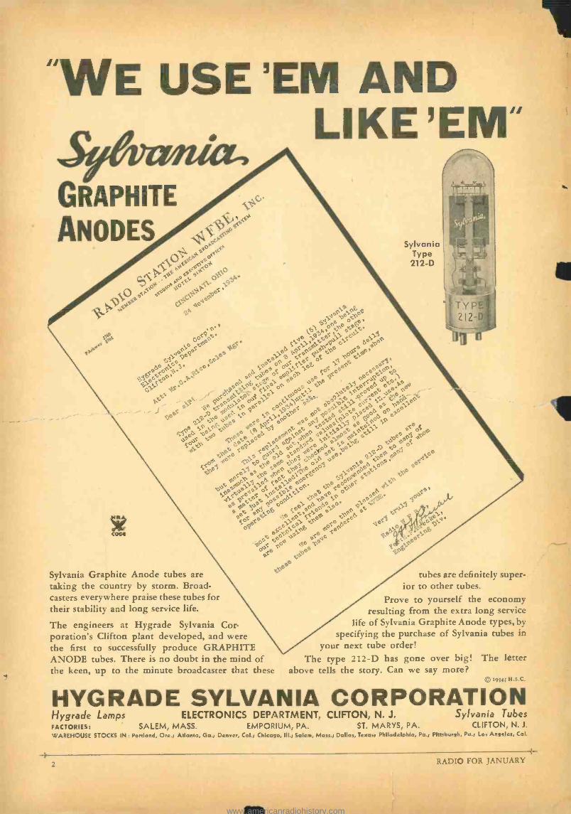
DON'T be misled by similarity of appearance or claims. Know the FACTS! HAMMARLUND Chokes have been proved different and better in all essential qualities. As evidence, the Ham -
marlund "CH -X" is the smallest and lightest R.F. choke made. Its features are exclusive. Only I/2" x 11/2", it is small enough for restricted spaces, and so light that the Finned copper leads are ample support. Leads extend straight from the end caps. This makes for neater wiring.
Mail Coupon for Details
itimmarlund PRODUCTS
RADIO FOR JANUARY
u i
"CH -500" TRANSMITTER CHOKE
End caps are small, thin and so spaced that distributed capacity to adjacent coils is at a minimum. Inductance 2.1 mh. Isolantite core. Priced so low it can be used generously wherever R.F. filtering is desirable -such as detector plate circuits, all B- leads, grid leads, etc. Only 75c each, less 40':, to experi- menters.
The Hammarlund "CH -500" Heavy -Duty Transmitter Choke delivers its highest useful impedance (more than 500,000 ohms) pre- cisely where wanted -at the 20, 40, 80 and 160 -meter amateur bands. Inductance 2.5 mh. Distributed capacity less than I... mmf. DC resistance 8 ohms. Maximum recommended DC (continuous) 500 milliamperes. Isolantite core, with no metal through center. Mounts with a single machine screw, with brackets re- moved. $1.75, less 40% to experimenters.
HAMMARLUND MANUFACTURING CO., 424 -438 W. 33rd St.. New York
Check here and attach 10c for 16-page Hammarlund 1935 Short-Wave Manual, illustrating and describing most popular SW circuits of past year, with schematic and picture diagrams and parts lists.
Check here for FREE information on Hammarlund Chokes.
Check here for FREE 1935 General Catalog.
Name
Address
3
www.americanradiohistory.com
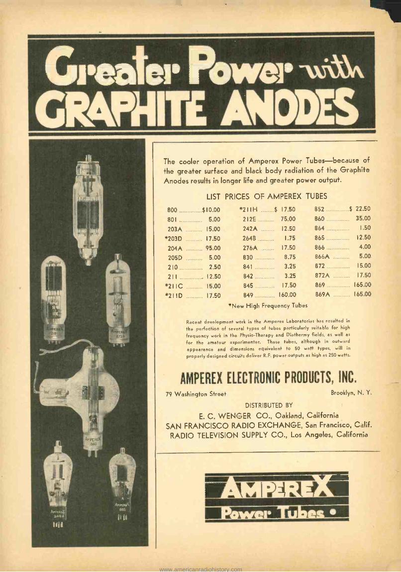
Greater Power -f'\.\' GR&PèIITE ANODES
The cooler operation of Amperex Power Tubes -because of
the greater surface and black body radiation of the Graphite Anodes results in longer life and greater power output.
LIST PRICES OF AMPEREX TUBES
800 $10.00 *211H $ 17.50 852 $ 22.50
801 5.00 212E 75.00 860 35.00
203A 15.00 242A 12.50 864 1.50
*203D 17.50 264B 1.75 865 12.50
204A 95.00 276A 17.50 866 4.00
205D 5.00 830 8.75 866A 5.00
210 2.50 841 3.25 872 15.00
211. 12.50 842 3.25 872A 17.50
*2110 15.00 845 17.50 869 165.00
*211D 17.50 849 160.00 869A 165.00
New High Frequency Tubes
Recent development work in the Amperex Laboratories has resulted in
the perfection of several types of tubes particularly suitable for high
frequency work in the Physio- Therapy and Diathermy fields, as well as
for the amateur experimenter. These tubes, although in outward
appearance and dimensions equivalent to 50 watt types, will in
properly designed circuits deliver R.F. power outputs as high as 250 watts.
AMPEREX ELECTRONIC PRODUCTS, INC.
79 Washington Street Brooklyn, N. Y.
DISTRIBUTED BY
E. C. WENGER CO., Oakland, California
SAN FRANCISCO RADIO EXCHANGE, San Francisco, Calif.
RADIO TELEVISION SUPPLY CO., Los Angeles, California
rof,. .27,71_ .
www.americanradiohistory.com
BRANCH OFFICES: New York City,
253 W. 128th St. Tel. MOnument 2 -2812
Boston, J. H. Condon, 6 Marlboro St.
Chicago, C. W. Nelson,
3618 North Bernard St. Los Angeles, Calif.
1455 Glenville Drive. Tel. CRestview 4017
ESTABLISHED 1917 Reg. U.S. Pat. Off.
}A NATIONAL MAGAZINE - PUBLISHED MONTHLY Publication Offices -Pacific Building, San Francisco, California
Clayton F. Bane, Editor H. W. Dickow, Business Manager. D. B. McGown, Technical Editor. Frank C. Jones, Ultra- Short -Wave- Engineering Editor.
Clair Foster, Amateur Activity Editor. George B. Hart, Contributing Editor. C. C. Anderson, Engineering Draftsman
25c per ccpy, $3.00 per year by subscription in
the U.S. $4.00 elsewhere. Send subscriptions to the San Francisco office. Entered as second class
matter at the Post Office at San Francisco, Cali- fornia, under the Act of March 3rd, 1879.
Vol 17 JANUARY, 1935 No. I
RADIOTORIAL COMMENT Worthwhile New "Q" Signals
WHEN an amateur CQs on the high - frequency end of the band it is gen- erally assumed that he covers only
that portion of the band when listening; he seldom goes beyond the middle of the dial. Thus those whose transmitters are tuned to the low- frequency end of the band are not often recognized by the high- frequency CQer, simply because he never gets to the other end of the band. Or vice versa.
A dyed -in- the -wool DX hunter covers his choice end of the band with great care, tunes slowly and depends upon his old ac- quaintances to answer his CQs. But the newcomer and the man who calls CQ for the purpose of raising anybody, anywhere in the band, has a different problem on his hands. Sometimes he starts to tune from the high - frequency end, sometimes from the other end. So that those who hear a CQ will know which end of the band the CQer will cover when he throws his switch to the receiving position, it is suggested by Art Bates of the CALL BOOK that a few new "Q" signals be added to the list. The suggestion is time- ly, should appeal to all good amateurs. Here are the proposed new signals:
g,HM ... I will begin listening at the high frequency end of this band, tuning towards the middle of the band.
Q,LM ... I will begin listening at the low frequency end of this band, tuning towards the middle of the band.
AMH ... I will begin listening at the mid- dle of this band, tuning towards the high frequency end. QL ... I will begin listening at the middle of this band, tuning towards the low frequency end..
Although Mr. Bates has already sent these proposed new "Q" designations to various domestic and foreign radio magazines, it has been suggested by a staff member of "RADIO' that the new signals be reduced to two in number, i.e., one signal to indicate that the operator is tuning from the high frequency end of the, band towards the mid- dle, and another signal indicating that he will tune from the low frequency end of the band towards the middle. QLO would in- dicate, "I start tuning from the low fre- quency end." QHY would indicate, "I start tuning from the high frequency end."
Thus only two new signals would be add- ed, both self -evident in character, the "LO" portion of the "Q" signal automatically means "LO Frequency" and "HY" means "HIGH Frequency." 'Twould be better to make it QHI instead of QHY, but for the laugh that HI has associated itself with.
An expression from the reader is asked for. Quick action is needed so that the new signals will be widely known and used when the next international tests are with us. Do you favor four new "Q" signals as suggest- ed by Bates, or only two new signals -QLO and QHY -as suggested by "RADIO "?
Thank You, Ever So Much! (( HE destiny of amateur radio is in T the hands of Congress," you were
told by the Political Editor in De- cember "RADIO." And a flood of letters from subscribers -far too many to answer individually, are stacked high in the editor's files. How to approach a Congressman? That's easy. Colonel Foster will present the plan in full in the next issue of this maga- zine. If you are seriously interested in the future welfare of amateur radio, you will
Uncle Sam fo Amateur Radio Spokesman: "If it's more privileges you want, why not come
up and see ME sometime?"
heed his timely advice and join the vast army of amateurs who have already pledged themselves to leave no stone unturned to prevent the frequency -grabbers from ultimate- ly putting V- wheels on sacred amateur ter- ritory.
Fortunately for the amateur, the President of the United States is a man of vision. Every amateur is ready to back him in the event of national emergency. We are going to ask him to back us, without a penny of cost to
our Qovernment or to our people, so that we will still be AMATEURS when the time of need arrives. If you thrive on fact, not fancy, you will find a lot of it in next month's "RADIO." Colonel Foser knows Washington and Washington knows Foster. Thus the constructive program of telling the amateur what to do and how to do it will be presented with full vigor in the months to come.
The First Successful 5 -Meter Super ELSEWHERE in these pages you read
what Frank C. Jones has accomplished in the form of 5 -meter reception via
the super- heterodyne route. Again, necessity was the mother of invention. The 5 -meter band is already overcrowded in many of the larger metropolitan areas. The super- regen- erative receiver must soon give 'way to in- expensive forms of 5 -meter super -hets. Until this time there has not been available a WORKABLE super for the ultra -high fre- quencies. The latest achievement of Frank C. Jones will be welcomed by experiment- ers, manufacturers, jobbers and retailers.
May this latest contribution to the art bring you greater pleasure and more thrills from your 5 -meter experiments.
TALKING about Frank C. Jones, turn back the pages of "RADIO" to 1925. Nine years ago, Jones was at work in
his laboratory, conducting a series of trans- mitter amplifier tests. The amplifier was coupled to the antenna by means of two wires. Accidentally, Frank Jones moved the feed wires closer together, found that the output was increased. Thereupon he twisted the two wires together and observed a marked increase in antenna current. And so "Link Coupling" was discovered. Unquestionably, this form of coupling has played one of the major roles in modern amateur practice; it seemed reasonable to assume that Link Coup- ling could also be applied to receiving equip- ment. Consequently, Frank Jones went to work to find out what would happen when an an- tenna is link -coupled to a detector circuit. Also in these pages is an article from his pen, tell- ing how to build a marvelous little amateur superheterodyne receiver which uses this new form of antenna coupling. If you like to "roll your own," here is your opportunity to build a receiver that is literally a hair - raiser. Thus "RADIO" starts the new year right, with a pair of editorial scoops that should be welcomed by all. The technical standard of the magazine will be vastly im- proved during 1935. It will be an exciting year for the radio amateur.
RADIO FOR JANUARY
www.americanradiohistory.com
A Deaf Mute Asks for an Amateur License * If this story does not make your heart throb, you are not worthy of the name "amateur ". For here is an appeal to every radio amateur in the United States to do his small part in helping Mr. Adolph Czajka of Chicago in bis efforts to secure an amateur license. Petitions from radio clubs should be sent directly to the Federal Communications Commission at Wash- ington.- Editor.
around hunts on the street. My wife says if I stay at home with my short wave receiving station I will be a good man."
And so Adolph stays home and listens to the world talk. There is the itch of brass in his fingers. He wants to talk back. He knows the code. He can handle a key. He knows how to build his transmitter. All he needs now is for Uncle Sam to temper
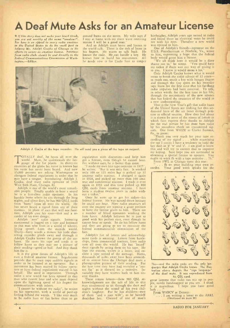
Adolph J. Czajka at the tape recorder. He will send you a piece of the tape on request.
TOTALLY deaf, he hears all over the world. Mute, he understands the lan- guage of the far places. In thirty -six
countries of the globe his name is known but his voice has never been heard. And now 15,000 persons are asking Washington to abrogate federal regulations in order that he may have a tongue. Introducing: Adolph J. Czajka, deaf mute radio operator of 2428 West 34th Place, Chicago, Ill.
Adolph is one of the world's most remark- able people. Totally unable to hear a sound he is a first -class radio operator. In his humble home where he sits through the long nights, and silent days, he has 900 QSLL cards from "hams" from all over the world. He has never heard a signal from any of their stations. In place of ears that will not func- tion, Adolph uses his eyes -that and a re- corder of his own design.
Adolph "sees" radio signals. Incoming continental is logged on a tape and becomes to this man who lives in a world of silence, living speech from the outside world. Thirty -forty words a minute his little chat- tering recorder plods away and through it Adolph Czajka knows the gossip of the air - lanes. He saves his tape and sends it to fellow hams so they may see a picture of their sending -good or bad. And they thank him for it.
It is the great dream of Adolph's life to own a federal amateur license. Regulations provide that he must copy audible signals in order to be licensed as an operator. But a movement has been started by fellow opera- tors to have federal regulations waived in his behalf. The need is imperative. Through radio a new world has been opened to this man who cannot hear and who must depend upon the lightning speed of his fingers for communication with others.
"I cannot be without my radio ", he writes on his typewriter, with a world of pent -up feeling behind the words. "I like very much to be radio ham or fan better than to go
regulations with discretion -and help him get a license, even though he cannot hear. For without ears, he is better than most.
"I made my own first tape- recorder in 1925 ", he writes. "But it was only fair. It worked only 100 or 125 miles but it picked up 32 amateur radio stations. I changed it again in 1928, and picked up more than 100 ama- teur and commercial stations. I made it over again in 1931 and this time picked up 800 QSL cards from amateur stations. I have been a student twelve years in radio with- out a ticket."
Once he went up to get his ticket -his federal license. He was turned down because he could not hear. Now radio amateurs all over the country are signing a giant petition to have the license given to him. There are a number of blind operators working the ham lanes. Adolph believes he is just as good with his perfect eyes, even though he cannot hear or speak. So do his fellow hams and they are going to try to convince the federal communication commission of the fact.
Adolph's list of letters and acknowledg- ment cards is amazing. Letters from battle- ships, from commercial stations, from radio men all over the world. He has "heard" their signals by seeing them on his tape. He logs the station, writes it a letter, and en- close a tape record of the message. Hams, thousands of miles away have been astonish- ed to receive from the Chicago deaf mute a photographic picture of their sending. For the first time they have had revealed a "rot- ten fist" as it showed on a recorder. In- variably they have written back to him sin- cere thanks.
These return letters -these 900 QSL ac- knowledgments are the salt of life to this man condemned to sit through the days and nights without the sound of his own chil- dren's laughter. For he has children -two of them "and a nice wife ", as he himself describes her. Cheated of one of man's
birthrights, Adolph years ago turned to radio and found there an electrical voice he could see with his eyes. Therafter a new world was opened to him.
One of Adolph's friends -operator on the U.S.S. Pontchartrain at Norfolk, Va., wrote to him, expressing a hope that the federal body would grant him a license.
"We all think here it would be a dirty shame not to," he wrote. "You could have my ticket if there was any way of giving it to you. I know it would mean a lot."
Only Adolph Czajka knows what it would mean to break the radio silence of 12 years - to reach out, touch a key with hungry fingers and through the tiny spots on his recorder tape learn for the first time that his far -flung radio impulses had been received. To talk, in other words, for the first time in his life, through the necromancy of the new science that has linked the countries of the world in a new understanding.
That is the New Year's gift that radio hams of the United States are seeking for this un- daunted hero of the air lanes through peti- tion to official sources. How they feel about it is shown by some of the scores of letters in which fans express their thanks to Adolph for the real service he has done ham radio by his soundless check on transmitted sig- nals. One from W8IZE at Clarke Summit, Pa., in point:
"Thank you very much for your tape re- cording of my signal . . . while examining the tap I notice I have a tendency to hold the last dash in '8" 'w' and 'z'. I am glad to know this and will try to correct that to improve my keying. Sure hope you are successful in obtaining a special license to operate. You ought to work fb with a tape recorder .. 73."
From 9WL at Chicago came this one: . fb on your building your own re-
corder. Your good work speaks for the
This -and the radio code are the only Ian
guages that Adolph Czajka knows. The illus tration above depicts the "sign language' of the deaf mute. It was reproduced from
his QSL card. great interest that radio can stir up in peo- ple, surely handicapped as you are. I think it is marvelous. I hope you have good luck..:'
From W8BCV at Detroit: " ... I am writing a letter to the ARRL
(Continued on page 18)
f RADIO FOR JANUARY
www.americanradiohistory.com
Ar THE Fresno convention a motion was made to split the Pacific Division in two and make the southern half
a new division. It was made by W. W. Mamey, W6EQM, the ranking officer of the new little group with the new big name, "Federation of Radio Clubs of the South- west, ARRL, a California Corporation ". Gen- erally speaking, resoluting at ham gather- ings is merely a form of pastime and about as futile as praying for rain in Death Valley. The accompanying arguments do, however, give us a chance to blow off steam. Some of us like to "debate ", some of us blow tin whistles, some hammer out calls on the steam pipes. Some of us ease the pressure merely by "seconding" motions and casting votes in all directions -long, loud and often. As most pleasures are largely in their an- ticipation, we hams get ours from the pic- tures our wishes present in these "resolu- tions." The fact that their objects are sel- dom realized and always soon forgot takes none of the pleasure from the making of them.
We older hams who are more or less "sales - proof" -more or less immune to herd emo- tionalism -vote perfunctorily if we vote at all. We know perfectly well that when a ham assemblage votes to raise the power limit of stations it has just as much effect on the Federal Communications Commission as throwing stones at the moon. There is an intelligent and forthright way of getting more power for amateur stations but men of experience know that firing broadsides at ONE ANOTHER at hamfests will never get it.
But occasionally there appears a resolu- tion that concerns only the machinery of the amateurs' own organization. Such move- ments do hold the possibility of bearing fruit -sweet or sour, as the case may be. This motion of the "Federation" to secede from the Pacific Division and force Southern California to become a part of a new divi- sion was of this nature -an internal ARRL affair. The younger element of the south had been well proselyted in advance, so there were many pairs of lungs under high com- pression with suppressed "Ayes ". When the chairman called for these ayes the hall was filled with them. Surmising that there would be few "Noes" I put plenty of steam back of mine to make it go as far as possible. And I had the proud distinction of voicing the ONLY "no" ! Perhaps "Ten thousand Frenchmen can't be wrong ", but I'll swear that one hundred hams can -when well nar- cotized beforehand. I was asked if I would be willing to give my reasons for voting "no." I replied that I would do so in writing. I hereby do.
This plan of the Little ARRL, Incorporated, however sinister, is fairly easy of accomplish- ment, provided the Warner -Segal -Maxim combine desires it. That combine, the key man of which is Warner, controls a major- ity of the ARRL directors. It controls like- wise the executive committee, all of the acts of which are invariably accepted by the ruling majority of the board as their own acts. Warner encountered no obstacles in throwing the Philippines out of the Pacific Division and actually disfranchising the Philippine members in 1930. This was done not only without the knowledge and con- sent of the Pacific Division but even without the knowledge of the Philippine members themselves! And the Philippines STAYED out until 1932 -until Warner was apprised by the then director of this division that un- less the Philippine members were restored to
I Voted "NO" By COL. C. FOSTER, W6HM
their rightful status he and the directors would be taken into court and FORCED to put them back. Now, if Warner could en- gineer such a violation of all the canons of courtesy and justice as that he could as easly, with the backing of this resolution of the Little ARRL, Incorporated, remove South- ern California and Utah, (or any other state), from the Pacific Division. In the Philippine case Warner made the mistake of keeping the project secret from the division members. I suspect that in the present case he is avoid- ing his former mistake by permitting the present plan to "originate" in an open meet- ing of Pacific Division amateurs -even though only 155 of the 536 registrants at this convention claimed membership in the ARRL. In which event he would have an alibi such as he failed to provide for himself in the Philippine case. History has a way of re- peating itself and the amateur who is un- acquainted with it or ignores its lessons is losing the greatest opportunity for seeing what is going on under the surface today.
The Little ARRL, Incorporated, is a fed- eration only in name. The association of the amateur body with it is loose in the extreme. Its members are such of the southern clubs as have joined it. Its meetings consist of its officers and such "delegates" of the mem- ber clubs as put in an appearance. The rank and file of the clubs know little and care less of the inner workings of Little ARRL, Inc. The scheme is to make a small group appear to be speaking for a large body of amateurs -to make the Little ARRL, Inc., appear to be speaking for all the amateurs of Southern California, just as the Big ARRL, Inc., has conveyed the impression that it is composed wholly of amateurs and that it speaks for all the amateurs of the United States, while in fact it is composed largely of commercial radio people and other non - amateurs with only a small proportion of the amateurs of America in it. Its motivation is essentially the aim of a few men to domi- nate the amateurs of Southern California, re- gardless of how few may have any interest in either the Little ARRL, Inc., or the Big ARRL, Inc. However wholehearted may be the moving spirits of the Little ARRL, back of it all lies the aspiration to shine as IT.
It is common belief that this group of secessionists is a Warner outfit. There is much evidence to substantiate the belief. The character of correspondence between the group and the ARRL headquarters points to it. And last year when the San Jose Club - long villified by headquarters- sponsored the division convention, no headquarters man was sent to it -while not long afterwards when the newly hatched "federation" worked up a hamfest under its own name Warner sent his right -hand man, Budlong. The only instance of which I have heard of the ARRL's money being spent to send a man clear across the continent to a mere hamfest. At the Fresno convention it was again Budlong. Much of his time was spent in the company of officers of the Little ARRL. And after the convention he was again with them in and around Los Angeles. If Budlong had disapproved of the Federation's plan to dis- rupt the Pacific Division it is a cinch that Matney would never have offered his reso- lution. The plan must have had at least Budlong's tacit approval. It would not have had his approval without having Warner's approval. So much is certain; for with Bud - long as with everyone else on Warner's staff he plays Warner's game or he loses his job.
And fat jobs aren't picked out of the bushes these days.
Officers of the Little ARRL definitely ap- proved Warner's action in failing to report the truth of the Madrid convention. They approved of Warner's actions in Washington against the efforts of amateurs all over the country who were striving to prevent rati- fication of the new amateur restriction, thus providing the spectacle of a group of ama- teurs siding with the commercial element that had contrived the new restriction -the spectacle of Pacific Division amateurs ap- proving a new restriction devised for killing the greatest continuous public service ever performed by the amateurs (and performed almost wholly by Pacific Division amateurs) -the trans- Pacific traffic. So when we call this group of secessionists a Warner outfit we do so with deep conviction.
The proponents of the secession plan had only two reasons to advance for it. They had some arguments besides, but when their talk was divested of inconsequentials and irrele- vancies the reasons boiled down to just two - (1), That Mr. Culver, director for the divi- sion, lives too far from them to come and see them as often as they would like, and, (2), That the ARRL members of the division are so numerous they cannot be properly rep- resented by one director at the yearly meet- ings of the board.
As for No. 1 -There are some wise, grown- up amateurs in Southern California, and in all the years of the Pacific Division's exist- ence none of these men has ever intimated that a director residing in the San Francisco area was too far away. Anyone in any part of the division who wishes to confer per- sonally with the director is welcome to do so. If a man wishes to see the director there is no reason why the director should always be the man to do the traveling. The director attends a number of important gatherings each year in different parts of the division. There is no reason why a director should attend every hamfest, nor does he -even in his own vicinity. If he had no better use for his time than running to hamfests all over the map he would not be exhibiting the common sense needed for a director. Peren- nial playboys and glad- handers don't make dependable directors. In all the history of the division no intelligent ham ever before kicked because the director resided approxi- mately in the middle of the division. And just remember that Hawaii and the Philip- pines are also in the Pacific Division.
Claim No. 2 is wholly specious. The truth of the situation is that the secessionists don't like Culver. If they did, it would not have occurred to them that they themselves needed a different director. In their dislike for Culver they are disclosing either that they cannot recognize outstanding ability and character or else that they are taking their cue from someone else who doesn't like him. The ARRL headquarters does not like him; and for the sufficient reason that of all the directors at present on the board he and Director Jabs are the only two who are bent upon cleaning up the mess the ARRL is in. This is the common knowledge of discern- ing amateurs throughout the United States.
Just presume, for the sake of argument, that the secessionists had got their new divi- sion. They would, of course, expect to name a man of their own way of thinking as its director. Now, at the last meeting of the ARRL board, 14 of the 16 directors approved Warner's Madrid conduct just as did the secessionists; so the men of the Little ARRL, Inc., cannot well maintain that they need
(Continued on page 33)
RADIO FOR JANUARY 7
www.americanradiohistory.com
The First Practical 5 -Meter Super The writer, in common with other 5 -meter
experimenters, has always had better luck with super -regenerative receivers than with any other type on the 5 -meter band. An analysis of the situation brought out some interesting points, so another superhetero- dyne receiver was built and the results have been very gratifying. The sensitivity and selectivity of this receiver is better than any super -regenerative receiver that I have ever tested.
For present day purposes, a receiver must tune broadly enough to cover from 50
By FRANK C. JONES Ultra -Short Wave Editor
The RF stage provides a little additional gain where it is really needed, reduces image interference, and removes antenna resonance absorption spots from the regenerative cir- cuit. This combination brings in 5 -meter signals that are inaudible on super- regenera- tive sets using a stage of TRF. The same results were obtained in comparing it with an ordinary transceiver set.
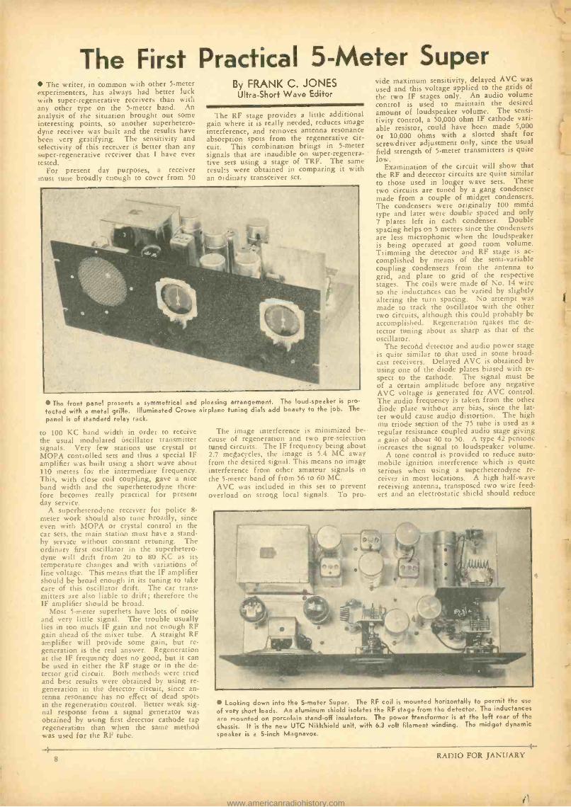
The front panel presents a symmetrical and tested with a metal grille. Illuminated Crowe panel is of standard relay rack.
to 100 KC band width in order to receive the usual modulated oscillator transmitter signals. Very few stations use crystal or MOPA controlled sets and thus a special IF amplifier was built using a short wave about 110 meters for the intermediate frequency. This, with close coil coupling, gave a nice band width and the superheterodyne there- fore becomes really practical for present day service.
A superheterodyne receiver for police 8-
meter work should also tune broadly, since even with MOPA or crystal control in the car sets, the main station must have a stand- by service without constant retuning. The ordinary first oscillator in the superhetero- dyne will drift from 20 to 80 KC as its temperature changes and with variations of line voltage. This means that the IF amplifier should be broad enough in its tuning to take care of this oscillator drift. The car trans- mitters are also liable to drift; therefore the IF amplifier should he broad.
Most 5 -meter superhets have lots of noise and very little signal. The trouble usually lies in too much IF gain and not enough RF gain ahead of the mixer tube. A straight RF amplifier will provide some gain, but re- generation is the real answer. Regeneration at the IF frequency does no good, but it can be used in either the RF stage or in the de- tector grid circuit. Both methods were tried and best results were obtained by using re- generation in the detector circuit, since an- tenna resonance has no effect of dead spots in the regeneration control. Better weak sig- nal response from a signal generator was obtained by using first detector cathode tap regeneration than when the same method was used for the RF tube.
pleasing arrangement. The loud- speaker is pro -
airplane tuning dials add beauty to the job. The
The image interference is minimized be- cause of regeneration and two pre -selection tuned circuits. The IF frequency being about 2.7 megacycles, the image is 5.4 MC away from the desired signal. This means no image interference from other amateur signals in the 5 -meter band of from 56 to 60 MC.
AVC was included in this set to prevent overload on strong local signals. To pro-
vide maximum sensitivity, delayed AVC was used and this voltage applied to the grids of the two IF stages only. An audio volume control is used to maintain the desired amount of loudspeaker volume. The sensi- tivity control, a 50,000 ohm IF cathode vari- able resistor, could have been made 5,000 or 10,000 ohms with a slotted shaft for screwdriver adjustment only, since the usual field strength of 5 -meter transmitters is quite low.
Examination of the circuit will show that the RF and detector circuits are quite similar to those used in longer wave sets. These two circuits are tuned by a gang condenser made from a couple of midget condensers. The condensers were originally 100 mmfd type and later were double spaced and only ' plates left in each condenser. Double spacing helps on 5 meters since the condensers are less microphonic when the loudspeaker is being operated at good room volume. Trimming the detector and RF stage is ac- complished by means of the semi -variable coupling condensers from the antenna to grid, and plate to grid of the respective stages. The coils were made of No. 14 wire so the inductances can be varied by slightly .filtering the turn spacing. No attempt was made to track the oscillator with the other two circuits, although this could probably be accomplished. Regeneration makes the de- tector tuning about as sharp as that of the oscillator.
The secotd detector and audio power stage is quite similar to that used in some broad- cast receivers. Delayed AVC is obtained by using one of the diode plates biased with re- spect to the cathode. The signal must be of a certain amplitude before any negative AVC voltage is generated for AVC control. The audio frequency is taken from the other diode plate without any bias, since the lat- ter would cause audio distortion. The high mu triode section of the 75 tube is used as a
regular resistance coupled audio stage giving a gain of about 40 to 50. A type 42 pentode increases the signal to loudspeaker volume.
A tone control is provided to reduce auto- mobile ignition interference which is quite serious when using a superheterodyne re- ceiver in most locations. A high half -wave receiving antenna, transposed two wire feed- ers and an electrostatic shield should reduce
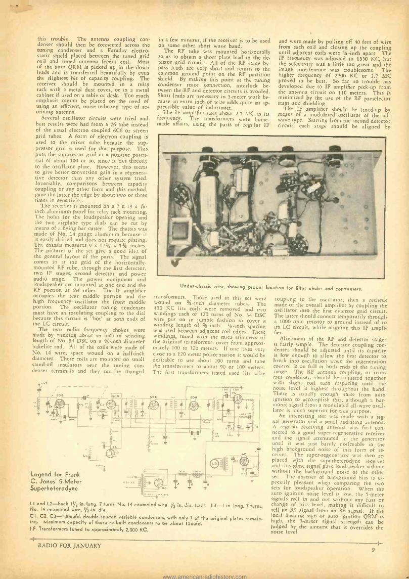
Looking down into the 5 -meter Super. The RF coil is mounted horizontally to permit the use
of very short leads. An aluminum shield isolates the RF stage from the detector. The inductances
are mounted on porcelain stand -off insulators. The power transformer is at the left rear of the
chassis. It is the new UTC Niklshield unit, with 6.3 volt filament winding. The midget dynamic
speaker is a 5 -inch Magnavox.
8 RADIO FOR JANUARY
i' www.americanradiohistory.com
this trouble. The antenna coupling con- denser should then be connected across the tuning condenser and a Faraday electro- static shield placed between the tuned grid coil and tuned antenna feeder coil. Most of the auto QRM is picked up in the down leads and is transferred beautifully by even the slightest bit of capacity coupling. The receiver should be mounted in a relay rack with a metal dust cover, or in a metal cabinet if used on a table or desk. Too much emphasis cannot be placed on the need of using an efficient, noise -reducing type of re- ceiving antenna.
Several oscillator circuits were tried and best results were had from a 76 tube instead of the usual electron coupled 6C6 or screen grid tubes. A form of electron coupling is used to the mixer tube because the sup- pressor grid is used for that purpose. This puts the suppressor grid at a positive poten- tial of about 100 or so, since it ties directly to the oscillator plate. However, this seems to give better conversion gain in a regenera- tive detector than any other system tried. Invariably, comparisons between capacity coupling or any other form and this method, gave the latter the edge by about two or three times in sensitivity.
The receiver is mounted on a 7 x 19 x iR- inch aluminum panel for relay rack mounting. The holes for the loudspeaker opening and the two airplane type dials can be cut by means of a flying bar cutter. The chassis was made of No. 14 gauge aluminum because it is easily drilled and does not require plating The chassis measures 9 x 171/2 x 11/4 inches. The pictures of the set give a good idea of the general layout of the parts. The signal comes in at the grid of the horizontally -
mounted RF tube, through the first detector, two IF stages, second detector and power audio stage. The power equipment and loudspeaker are motinted at one end and the RF portion at the other. The IF amplifier occupies the rear middle portion and the high frequency oscillator the front middle portion. The oscillator tuning condenser must have an insulating coupling to the dial because this circuit is "hot" at both ends of the LC circuit.
The two radio frequency chokes were made by winding about an inch of winding length of No. 34 DSC on a % -inch diameter bakelite rod. All of the coils were made of No. 14 wire, space wound on a half -inch diameter. These coils are mounted on small stand -off insulators near the tuning con- denser terminals and they can be changed
in a few minutes, if the receiver is to be used on some other short wave band.
The RF tube was mounted horizontally so as to obtain a short plate lead to the de- tector grid circuit.. All of the RF stage by- pass leads are very short and return to the common ground point on the RF partition shield. By making this point at the tuning condenser rotor connection, interlock be- tween theRF and detector circuits is avoided. Short leads are necessary in 5 -meter work be- cause an extra inch of wire adds quite an ap- preciable value of inductance.
The IF amplifier uses about 2.7 MC as its frequency. The transformers were home- made affairs, using the parts of regular IF
and were made by pulling off 40 feet of wire from each coil and closing up the coupling until adjacent coils were 1/4 -inch apart. The IF frequency was adjusted to 1550 KC, but the selectivity was a little too great and the image interference was troublesome. The higher frequency of 2700 KC or 2.7 MC proved to be best. So far no trouble has developed due to IF amplifier pick -up from the antenna circuit on 110 meters. This is minimized by the use of the RF preselector stags and shielding.
The IF amplifier should be lined -up by means of a modulated oscillator of the all - wave type. Starting from the second detector circuit, each stage should be aligned by
Under -chassis view, showing proper location for filter choke and condensers.
transformers. Those used in this set were wound on % -inch diameter tubes. The 450 KC litz coils were removed and two windings each of 120 turns of No. 34 DSC wire put on in jumble fashion to cover ,t winding length of % -inch. 1/4-inch spacing was used between adjacent coil edges. These windings, tuned with the mica trimmers of the original transformer, cover from approxi- mately 100 to 120 meters. If one lives very close to a 120 meter police station it would be desirable to use about 100 turns and tune the transformers to about 90 or 100 meters. The first transformers tested used litz wire
Legend for Frank C. Jones' 5 -Meter Superheterodyne
LI and L2 -Each 11/2 in. long, 7 turns, No. 14 enameled wire, 1/2 in. pia. urns. L3 -I in. long, 7 turns, No. 14 enameled wire, 1 /2 -in. dia. CI, C2, C3- 100uufd. double -spaced variable condensers, with only 7 of the original plates remain- ing. Maximum capacity of these re -built condensers to be about ISuufd. I.F. Transformers tuned to approximately 2,000 KC.
coupling to the oscillator, then a recheck made of the overall amplifier by coupling the oscillator into the first detector grid circuit. The latter should connect temporarily through a 1000 ohm resistor to ground instead of to its LC circuit, while aligning this IF ampli- fier.
Alignment of the RF and detector stages is fairly simple. The detector coupling con- denser should be adjusted until its capacity is low enough to allow the first detector to break into oscillation when the regeneration control is on full at both ends of the tuning range. The RF antenna coupling, or trim- mer condenser, should be adjusted together with slight coil turn respacing until the noise level is highest throu ̂ hour the band. There is usually enough noise from auto ignition to accomplish this, although a har- monic signal from a modulated all -wave oscil- lator is much superior for this purpose.
An interesting test was made with a sig- nal generator and a small radiating antenna. A regular receiving antenna was first con- nected to a good super- regenerative receiver and the signal attenuated in the generator until it was just barely noticeable in the high background noise of this form of re- ceiver. The super -regenerator was then re- placed with the superheterodyne receiver and this same signal gave loudspeaker volume without the background noise of the other set. The absence of background hiss is es- pecially pleasant when comparing the two sets for loudspeaker operation. When the auto ignition noise level is low, the 5 -meter signals roll in and out without any fuss or change of hiss level, making it difficult to tell an R9 signal from an R6 signal. If the local flashing sign or auto ignition QRM is high, the 5 -meter signal strength can be judged by the amount that it overrides the noise level.
RADIO FOR JANUARY
www.americanradiohistory.com
What Goes On Inside a Vacuum Tube The common triode type of vacuum tube
has three elements; a heated cathode, which is the source of the electrons, a control grid, which controls the flow of electrons from the cathodes and a plate, or anode, which re-
ceives the electrons which are thrown off the cathode.
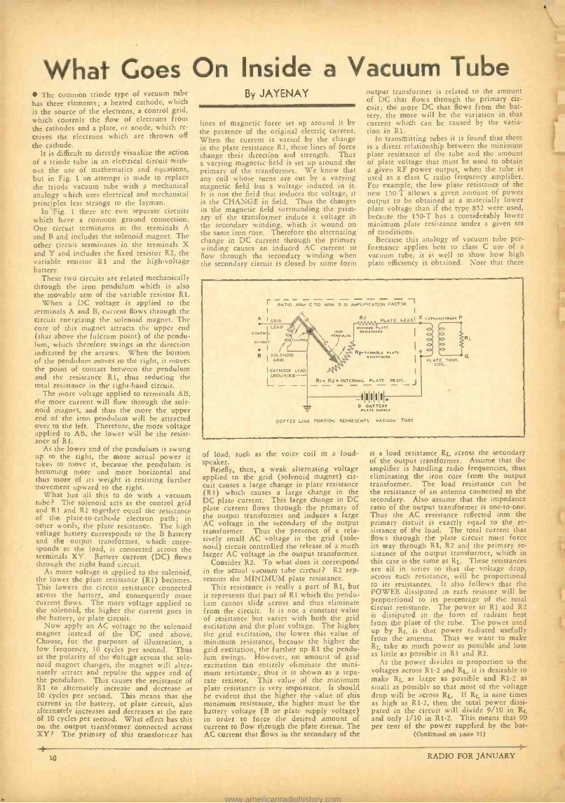
It is difficult to directly visualize the action of a triode tube in an electrical circuit with- out the use of mathematics and equations, but in Fig. 1 an attempt is made to replace the triode vacuum tube with a mechanical analogy which uses electrical and mechanical principles less strange to the layman.
In Fig. 1 there are two separate circuits which have a common ground connection. One circuit terminates in the terminals A and B and includes the solenoid magnet. The other circuit terminates in the terminals X and Y and includes the fixed resistor R2, the variable resistor R1 and the high -voltage battery.
These two circuits are related mechanically through the iron pendulum which is also the movable arm of the variable resistor R1.
When a DC voltage is applied to the terminals A and B, current flows through the circuit energizing the solenoid magnet. The core of this magnet attracts the upper end (that above the fulcrum point) of the pendu- lum, which therefore swings in the direction indicated by the arrows. When the bottom of the pendulum moves to the right, it moves the point of contact between the pendulum and the resistance R1, thus reducing the total resistance in the right -hand circuit.
The more voltage applied to terminals AB, the more current will flow through the sole- noid magnet, and thus the more the upper end of the iron pendulum will be attracted over to the left. Therefore, the more voltage applied to AB, the lower will be the resist- ance of R I.
As the lower end of the pendulum is swung up to the right, the more actual power it takes to move it, because the pendulum is becoming more and more horizontal and thus more of its weight is resisting further movement upward to the right.
What has all this to do with a vacuum tube? The solenoid acts as the control grid and Ri and R2 together equal the resistance of the plate -to- cathode electron path; in other words, the plate resistance. The high voltage battery corresponds to the B battery and the output transformer, which corre- sponds to the load, is connected across the terminals XY. Battery current (DC) flows through the right hand circuit.
As more voltage is applied to the solenoid, the lower the plate resistance (R1) becomes. This lowers the circuit resistance connected across the battery, and consequently more current flows. The more voltage applied to the solenoid, the higher the current goes in the battery, or plate circuit.
Now apply an AC voltage to the solenoid magnet instead of the DC used above. Choose, for the purposes of illustration, a low frequency, 10 cycles per second. Thus as the polarity of the voltage across the sole- noid magnet changes, the magnet will alter- nately attract and repulse the upper end of the pendulum. This causes the resistance of R1 to alternately increase and decrease at 10 cycles per second. This means that the current in the battery, or plate circuit, also alternately increases and decreases at the rate of 10 cycles per second. What effect has this on the output transformer connected across XY? The primary of this transformer has
By JAYENAY
lines of magnetic force set up around it by the presence of the original electric current. When the current is varied by the change in the plate resistance R1, these lines of force change their direction and strength. Thus a varying magnetic field is set up around the primary of the transformer. We know that any coil whose turns are cut by a varying magnetic field has a voltage induced in it. It is not the field that induces the voltage, it is the CHANGE in field. Thus the changes in the magnetic field surrounding the prim- ary of the transformer induce a voltage in the secondary winding, which is wound on the same iron core. Therefore the alternating change in DC current through the primary winding causes an induced AC current to flow through the secondary winding when the secondary circuit is closed by some form
output transformer is related to the amount of DC that flows through the primary cir- cuit; the more DC that flows from the bat- tery, the more will be the variation in that current which can be caused by the varia- tion in R1.
In transmitting tubes it is found that there is a direct relationship between the minimum plate resistance of the tube and the amount of plate voltage that must be used to obtain a given RF power output, when the tube is used as a class C radio frequency amplifier. For example, the low plate resistance of the new 150 -T allows a given amount of power output to be obtained at a materially lower plate voltage than if the type 852 were used, because the 150 -T has a considerably lower minimum plate resistance under a given set of conditions.
Because this analogy of vacuum tube per- formance applies best to class C use of a vacuum tube, it is well to show how high plate efficiency is obtained. Note that there
r RATIO ARM C TO ARM D IS AMPLIFICATION FACTOR -I I
A I GRID
I LEAD
1
tCOIT 1
B SOLENOID
GRID
I CATHODE LEAD GROUNDED
2 PLATE LEAD' X ITAAwatoAUt P
OR, Tt
amsiAwct
RI-rut nAe wct
RI. R2- INTERNAL PLATE RESIST
- 11111111 B BATTERY
DOTTED LINE PORTION REPRESCNTS VACUUM TUBE
Y
PLATE TANT. COIL
of load, such as the voice coil in a loud- speaker.
Briefly, then, a weak alternating voltage applied to the grid (solenoid magnet) cir- cuit causes a large change in plate resistance (R1) which causes a large change in the DC plate current. This large change in DC plate current flows through the primary of the output transformer and induces a large AC voltage in the secondary of the output transformer. Thus the presence of a rela- tively small AC voltage in the grid (sole- noid) circuit controlled the release of a much larger AC voltage in the output transformer.
Consider R2. To what does it correspond in the actual vacuum tube circuit? R2 rep- resents the MINIMUM plate resistance.
This resistance is really a part of R1, but it represents that part of R1 which the pendu- lum cannot slide across and thus eliminate from the circuit. It is not a constant value of resistance but varies with both the grid excitation and the plate voltage. The higher the grid excitation, the lower this value of minimum resistance, because the higher the grid excitation, the further up R1 the pendu- lum swings. However, no amount of grid excitation can entirely eliminate the mini- mum resistance; thus it is shown as a sepa- rate resistor. This value of the minimum plate resistance is very important. It should be evident that the higher the value of this minimum resistance, the higher must be the battery voltage (B or plate supply voltage) in order to force the desired amount of current to flow through the plate circuit. The AC current that flows in the secondary of the
is a load resistance RL across the secondary of the output transformer. Assume that the amplifier is handling radio frequencies, thus eliminating the iron core from the output transformer. The load resistance can be the resistance of an antenna connected to the secondary. Also assume that the impedance ratio of the output transformer is one -to -one. Thus the AC resistance reflected into the primary circuit is exactly equal to the re- sistance of the load. The total current that flows through the plate circuit must force its way through R1, R2 and the primary re- sistance of the output transformer, which in this case is the same as RL. These resistances are all in series so that the voltage drop, across each resistance, will he proportional to its resistances. It also follows that the POWER dissipated in each resistor will be proportional to its percentage of the total circuit resistance. The power in R1 and R2 is dissipated in the form of radiant heat from the plate of the tube. The power used up by RL is that power radiated usefully from the antenna. Thus we want to make RL take as much power as possible and lose as little as possible in R1 and R2.
As the power divides in proportion to the voltages across R1 -2 and RL, it is desirable to make RL as large as possible and RI -2 as small as possible so that most of the voltage drop will be across RL. If RL is nine times as high as R1 -2, then the total power dissi- pated in the circuit will divide 9/10 in RL and only 1 /10 in R1 -2. This means that 90 per cent of the power supplied by the bat -
(Continued on page 31)
10 RADIO FOR JANUARY
www.americanradiohistory.com
Practical High Fidelity TO THOSE of us who have watched the
progress of radio reception from its in- fancy, the forward movement of the
past two years has been of considerable in- terest. Not only is the engineering fraternity beginning to talk in terms of high fidelity, but high fidelity is actually being sold to the public. The user of broadcast facilities is beginning to realize that in addition to fine studios and artists, program reproduction must have a low distortion level. In keeping with this, broadcast stations are continuously improving fidelity; lines are being equalized
CEILING ACOO4T CAL
ROCH ACOUSTICAL `TREATMENT /RII
PLRIIORATEO METAL TO
SOUND OIISTRiuiIó:
FIG.1 and better audio equipment is being devel- oped. Unfortunately, not all stations have been able to completely modernize their equipment. Using a real high fidelity radio receiver harmonic distortion and frequency discrimination become quickly apparent and as the dial is twirled to different frequen- cies, the high fidelity broadcast stations can readily be separtaed from those affording mediocre program fidelity.
Unfortunately, high fidelity as it has been applied to radio receivers during the past year has to an extent been too theoretical. From an engineering viewpoint, it is easy to picture a high fidelity mike placed in an ideal studio -working through a high fidel- ity transmitter at the broadcast end. It is also easy to picture a flat top tuner -a straight line amplifier -a high fidelity speak- er combination at the receiving end. There is but one flaw in this entire picture, namely, acoustic operating conditions. While a mi- crophone or speaker may have a perfect characteristic thirty feet off the ground in an ideal open air test, how will these units operate respectively in the studio or your home?
The importance of acoustics in the broad-
DEFLECTOR PLATES Ar FIBRE OR METAL
FIG. 2
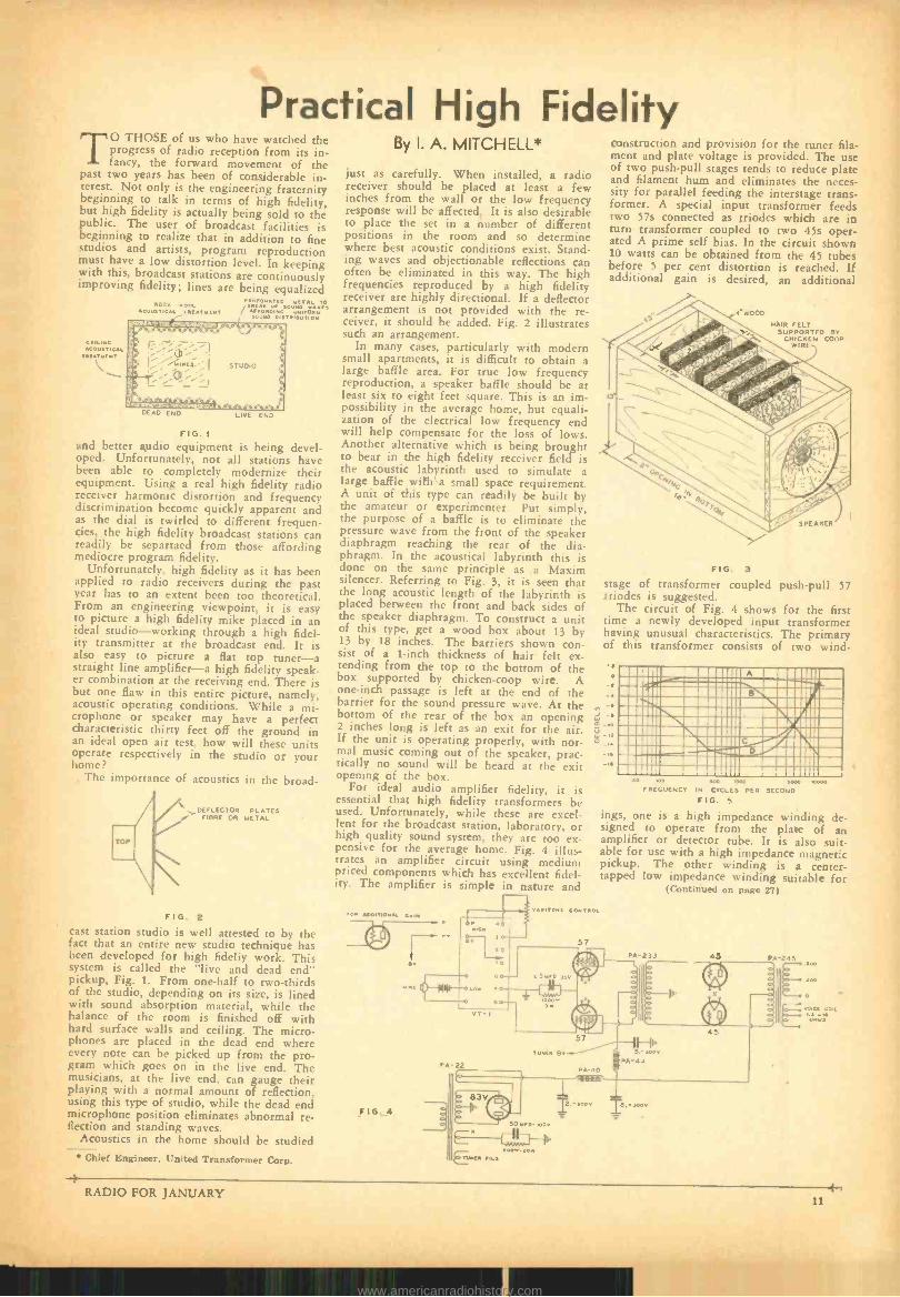
cast station studio is well attested to by the fact that an entire new studio technique has been developed for high fideliy work. This system is called the "live and dead end" pickup, Fig. 1. From one -half to two -thirds of the studio, depending on its size, is lined with sound absorption material, while the balance of the room is finished off with hard surface walls and ceiling. The micro- phones are placed in the dead end where every note can be picked up from the pro- gram which goes on in the live end. The musicians, at the live end, can gauge their playing with a normal amount of reflection, using this type of studio, while the dead end microphone position eliminates abnormal re- flection and standing waves.
Acoustics in the home should be studied Chief Engineer, United Transformer Corp.
By I. A. MITCHELL*
just as carefully. When installed, a radio receiver should be placed at least a few inches from the wall or the low frequency response will be affected. It is also desirable to place the set in a number of different positions in the room and so determine where best acoustic conditions exist. Stand- ing waves and objectionable reflections can often be eliminated in this way. The high frequencies reproduced by a high fidelity receiver are highly directional. If a deflector arrangement is not provided with the re- ceiver, it should be added. Fig. 2 illustrates such an arrangement.
In many cases, particularly with modern small apartments, it is difficult to obtain a large baffle area. For true low frequency reproduction, a speaker baffle should be at least six to eight feet square. This is an im- possibility in the average home, but equali- zation of the electrical low frequency end will help compensate for the loss of lows. Another alternative which is being brought to bear in the high fidelity receiver field is the acoustic labyrinth used to simulate a large baffle with' a small space requirement. A unit of this type can readily be built by the amateur or experimenter. Put simply, the purpose of a baffle is to eliminate the pressure wave from the front of the speaker diaphragm reaching the rear of the dia- phragm. In the acoustical labyrinth this is done on the same principle as a Maxim silencer. Referring to Fig. 3, it is seen that the long acoustic length of the labyrinth is placed between the front and back sides of the speaker diaphragm. To construct a unit of this type, get a wood box about 13 by 13 by 18 inches. The barriers shown con- sist of a 1 -inch thickness of hair felt ex- tending from the top to the bottom of the box supported by chicken -coop wire. A one -inch passage is left at the end of the barrier for the sound pressure wave. At the bottom of the rear of the box an opening 2 inches long is left as an exit for the air. If the unit is operating properly, with nor- mal music coming out of the speaker, prac- tically no sound will be heard at the exit opening of the box.
For ideal audio amplifier fidelity, it is essential that high fidelity transformers he used. Unfortunately, while these are excel- lent for the broadcast station, laboratory, or high quality sound system, they are too ex- pensive for the average home. Fig. 4 illus- trates an amplifier circuit using medium priced components which has excellent fidel- ity. The amplifier is simple in nature and
EOR ADDITIONAL GAIN
FIG. 4
IG
construction and provision for the tuner fila- ment and plate voltage is provided. The use of two push -pull stages tends to reduce plate and filament hum and eliminates the neces- sity for parallel feeding the interstage trans- former. A special input transformer feeds two 57s connected as triodes which are in turn transformer coupled to two 45s oper- ated A prime self bias. In the circuit shown 10 watts can be obtained from the 45 tubes before 5 per cent distortion is reached. If additional gain is desired, an additional
"WOOD
HAIR FELT SUPPORTED BY
CHICKEN COOP WIRE
FIG. 3
stage of transformer coupled push -pull 57 triodes is suggested.
The circuit of Fig. 4 shows for the first time a newly developed input transformer having unusual characteristics. The primary of this transformer consists of two wind-
N J 4
m ,O
14
° ,4
VARITONE CONTROL
57
1111I1111MIIIIIIOM-- 1 11!!; CC:.:::. -
1f111111111111111111:2M iC!11IMIIM111111 1111111111 1IIIIW EI11111IMI_ 11111 \11111J/Í111 iÌÌÌ\11111crI11211 lrCara ilet)%11112 IIMI11I11IÌÌ
so No Soo moo s000 FREQUENCY N CYCLES PER SECOND
FIG. S
ings, one is a high impedance winding de- signed to operate from the place of an amplifier or detector tube. It is also suit- able for use with a high impedance magnetic pickup. The other winding is a center - tapped low impedance winding suitable for
(Continued on page 27)
10000
45 PA 24
o
45
83V I,.
P sOM D IDDY
n
EU u N E L4
I.-4000 IB.-,DD.
t 0
RADIO FOR JANUARY 11
www.americanradiohistory.com
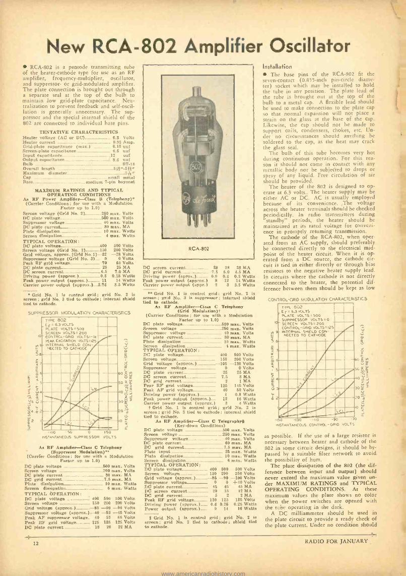
New RCA -802 Amplifier Oscillator RCA -802 is a pentode transmitting tube
of the heater -cathode type for use as an RF amplifier, frequency -multiplier, oscillator, and suppressor- or grid- modulated amplifier. The plate connection is brought out through a separate seal at the top of the bulb to maintain low grid -plate capacitance. Neu- tralization to prevent feedback and self- oscil- lation is generally unnecessary. The sup- pressor and the special internal shield of the 802 are connected to individual base pins.
TENTATIVE CHARACTERISTICS Heater voltage (AC or DC)....._...._......_._.._ 6.3 Volts Heater current . _.._.....___ __..._..... 0.95 Amp. Grid -plate capacitance (max.) 0.15 uuf Screen -plate capacitance .. _. 0.6 uuf Input capacitance _...._ _. _.. 12 uuf Output capacitance__ _ _ _ _.._ _._......_.........__... 8.6 uuf Bulb .......... ...... ST -16 Overall length _.._5Il " -5311" Maximum diameter _........._._ .._._........_.__.._......2//g" Cap _._ ___ _._ . _ small metal Base _._ medium 7 -pin bayonet
MAXIMUM RATINGS AND TYPICAL OPERATING CONDITIONS
As RF Power Amplifier -Class B (Telephony) (Carrier Conditions for use with a Modulation
Factor up to LO) Screen voltage (Grid No. 2).. _ 250 max. Volts DC plate voltage :n0 max. Volts Suppressor voltage 4u max. Volts DC plate current _ 30 max. MA Plate dissipation....___..... _. ....... 10 max. Watts Screen dissipation..._....___..._. _...___..._..__. 4 max. Watts TYPICAL OPERATION: DC plate voltage_..____.._._ . .........................400 500 Volts Screen voltage (Grid No 2)__._.__. ..... 150 200 Volts Grid voltage, approx. (Grid No. 1) -22 - -28 Volts Suppressor voltage (Grid No. 3) . 0 0 Volts Peak RF grid voltage .._._ ..............__........_. 70 DC plate current .............__..... 25 DC screen current ......... .....____..._._...._........6.5 Driving power (approx.) 0.5 Peak power output ( approx.)...._...._.. 11
Carrier power output (approx.) _.2.75
63 Volts 25 MA DC screen current 28 28 28 MA
7.0 MA DC grid current..... ...... _. 7.5 5.0 4.5 MA 0.18 Watts Driving power (apron.) ............._ 0.9 0.6 0.5 Watts
14 Watts Peak power output (approx.) 8 12 14 Watts 3.5 Watts Carrier power output (appr.) 2 3 3.5 Watts
Grid No. 1 is control grid ; grid No. 2 is screen ; grid No. 3 tied to cathode ; internal shield tied to cathode.
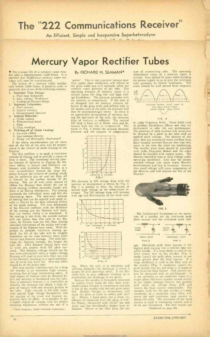
SUPPRESSOR MODULATION CHARlCTERSTICS
10
z
a 4 a
LL a
Q á
z î
)
1-¡6 í a 4 2
á2
Ñ
TYPE _Ef
PLATE SCREEN
" CONTROL PE
- INTERNAL NECTED
802 =6.3 VOLTS
VOLTS VOLTS= -GRID
EXCITATION SHIELD
TO
=500 200
VOLT 5=-9I DOLTS=125
CON CATHODE
;1II ill re _Ilk: ....AIM. s
-100 -SO O 50 NSTANTANEOUS SUPPRESSOR VOLTS
v
r:4 a
a
60Z0
5o$á L.)
Q 40.
ú 30 î
20 ô IO
CL
As RF Amplifier -Class C Telephony (Suppressor Modulation)**
(Carrier Conditions ; for use with a Modulation Factor up to 1.0)
DC plate voltage .__. _... ._ _.__500 max. Volts Screen voltage _ __...__..__.__. ._......200 max. Volts DC plate current 30 max. MA DC grid current _ 7.5 max. MA Plate dissipation ........ .............__........___..... 10 max. Watts Screen dissipation.....__ _ ....._... _.. 6 max. Watts TYPICAL OPERATION: DC plate voltage_...... _..._..._...._. 400 500 500 Volts
200 200 Volts Grid voltage ( approx.).._.._..........--RS -90 -90 Volts Suppressor voltage (approx.) -40 -53 -45 Volts Peak AF' suppressor voltage_. 40 53 65 Volts Peak RF grid voltage....._........... 125 125 125 Volts DC plate current __........._..._..._.. 18 20 22 MA
Grid No. I is control grid; grid No. 2 is screen ; grid No. 3 is suppressor ; Internal shield tied to cathode.
As RN' Amplifier -Class C Telephony (Grid Modulation)t
(Carrier Conditions; for use with a Modulation Factor up to 1.0)
DC plate voltage.... _.__ 500 max. Volts Screen voltage ...._.._..._...._...
Suppressor voltage .....
DC plate current..___.__...._ Plate dissipation ___........_.. Screen dissipation .. _..
TYPICAL OPERATION: DC plate voltage _._...._._._...
Screen voltage _... _......_......__
Grid voltage ( approx.)..._.._..._... Suppressor voltage _............_.._........
DC plate current screen current ....._.._.._ ...............
DC grid current.. .._..._..._.........._.........
Pear RF grid voltage ..................... Peak AF grid voltage ..................... Driving power (approx.) 1 0.8 Watts Peak power output ( approx.).__. 12 16 Watts Carrier power output (approx.) 3 4 Watts
t Grid No. 1 is control grid ; grid No. 2 is screen; grid No. 3 tied to cathode; internal shield tied to cathode.
As RF Amplifier -Class C Telegraphy§ (Key -down Conditions)
DC plate voltage . 500 max. Volts Screen voltage _............_....__........ __._..... ......_250 max. Volts Suppressor voltage. .....__....__.._.__.._.....__.. 40 max. Volts DCplate current........._ ........ ................_........._.... 60 max. MA DC grid current .........._...._............ ______ 7.5 max. MA Plate input ................._.._.. 25 max. Watts Plate dissipation ............._...._.._.._... 10 max. Watts Screen dissipation.. 6 max. Watts
.__250 max. Volts
.__. 40 max. Volts ..... 30 max. MA
..... 10 max. Watts 4 max. Watts
400 500 Volts 150 200 Volts = 105 -130 Volts
0 0 Volts 25 25 MA
7.5 8 MA 2 1 MA
125 145 Volts 40 50 Volta
TYPICAL OPERATION: 500 500 Volts 200 250 Volts
Grid voltage (approx.) ............._ --85 -90 -100 Volts Suppressor voltage ...._.._...._....__ 0 0 +40 Volts DC plate current ..........._...._....._...... 45 45 45 MA DC screen current ..................___... 20 15 12 MA DC grid current...._._....._.._.._._... 5 2 2 MA Peak RF grid voltage ....._...._..... 130 125 135 Volts Driving power (approx.) _ 0.6 0.25 0.25 Watts Power output ( approx.)_.._... 9 14 16 Watts
{ Grid No. 1 is control grid ; grid No. 2 is screen ; grid No. 3 tied to cathode ; shield tied to cathode.
Installation The base pins of the RCA -802 fit the
seven- contact (0.855 -inch pin -circle diame- ter) socket which may be installed to hold the tube in any position. The plate lead of the tube is brought out at the top of the bulb to a metal cap. A flexible lead should be used to make connection to the plate cap so that normal expansion will not place a
strain on the glass at the base of the cap. Likewise, the cap should not be made to support coils, condensers, chokes, etc. Un- der no circumstances should anything be soldered to the cap, as the heat may crack the glass seal.
The bulb of this tube becomes very hot during continuous operation. For this rea- son it should not come in contact with any metallic body nor be subjected to drops or spray of any liquid. Free circulation of air should he provided.
The heater of the 802 is designed to op- erate at 6.3 volts.. The heater supply may be either AC or DC. AC is usually employed because of its convenience. The voltage across the heater terminals should be checked periodically. In radio transmitters during "standby" periods, the heater should be maintained at its rated voltage for conveni- ence in promptly resuming transmission.
The cathode of the RCA -802, when oper- ated from an AC supply, should preferably be connected directly to the electrical mid- point of the heater circuit. When it is op- erated from a DC source, the cathode cir- cuit is tied in either directly or through bias resistors to the negative heater supply lead. In circuits where the cathode is not directly connected to the heater, the potential dif- ference between them should be kept as low
CONTROL-GRID MODULATION CHARACTERISTICS
Vr
D
á á m
TYPE 802 E r = 6.3 VOLTS PLATE VOLTS = SOO
SUPPRESSOR VOLTS =O SCREEN VOLTS =200 CONTROL -GRID VOLTS =I25 INTERNAL SHIELD CON NECTED TO CATHODE
-150 -130 - 10 -90 INSTANTANEOUS CO c TROL-OR'D
-70 VOLTS
as possible. If the use of a large resistor is necessary between heater and cathode of the 802 in some circuit designs, it should be by- passed by a suitable filter network to avoid the possibility of hum.
The plate dissipation of the 802 (the dif- ference between input and output) should never exceed the maximum value given un- der MAXIMUM RATINGS and TYPICAL OPERATING CONDITIONS. At these maximum values the plate shows no color when the power switches are opened with the tube operating in the dark.
A DC milliammeter should be used in the plate circuit to provide a ready check of the plate current. Under no condition should
RADIO FOR JANUARY
www.americanradiohistory.com

GRID Ns
ATE -METAL TOP CAP
the DC plate current exceed the maximum values given under MAXIMUM RATINGS and TYPICAL OPERATING CONDI- TIONS.
Suppressor grid voltage for the RCA -802 may be obtained from any suitable DC sup- ply. In cases where the suppressor draws current, the supply should be a battery or other DC source of good regulation.
The internal shield is brought out of the tube to its own separate base pin. The in- ternal shield should be tied to a terminal operating at zero RF and /or AF potential. In most cases this connection will be made to the cathode or suppressor terminal.
Adequate shielding and isolation of the input circuit and the output circuit are nec- essary if optimum results are to be obtained. If an external shield is employed with the 802, it should be designed to enclose the base end of the tube and extend up to a point level with the bottom of the internal shield. Clearance between the glass bulb and external shield should be at least 1/16 inch. The impedance between the screen and filament must be kept as low as possible by the use of a by -pass condenser.
When a new circuit is tried or when ad- justments are made, the plate voltage should be reduced in order to prevent damage to the rube or associated apparatus in case the circuit adjustments are incorrect. It is ad- visable to use a protective resistance of about 3000 ohms in series with the common negative high -voltage lead during such ad- justments.
The rated plate voltage of this tube is high enough to be exceedingly dangerous to the user. Great care should be taken during the adjustment of circuits, especially those in which the plate tank coil and condenser are at the DC plate potential. Application
As a Class B radio -frequency amplifier, RCA -802 may be used as shown under MAXIMUM RATINGS and TYPICAL OP- ERATING CONDITIONS. Grid No. 1 is the control grid; grid No. 2 is the screen; and grid No. 3 is tied to the cathode and serves as the suppressor. The shield is con- nected to cathode. In such service, the plate is supplied with unmodulated DC voltage and the grid is excited by RF voltage modu- lated at audio frequency in one of the pre- ceding stages. The plate dissipation for this class of operation should not exceed 10 watts.
Grid bias for the 802 as a Class B RF amplifier should be obtained from a battery or other DC source of good regulation. It should not be obtained from a high- resis- tance supply such as a grid -leak, nor from a rectifier, unless the latter has exceptionally good voltage regulation.
As a grid- modulated Class C RF amplifier, RCA -802 may be used as shown under MAXIMUM RATINGS and TYPICAL OP- ERATING CONDITIONS. Grid No. 1 is the control grid; grid No. 2 is the screen; and grid No. 3 is the suppressor. The shield is connected to cathode. In such service the plate is supplied by unmodulated DC late
voltage and the grid bias is modulated at audio frequency. Grid bias for this service should be obtained from a battery or other DC source of good regulation. It should not be obtained from a high- resistance supply.
As a suppressor -modulated Class C RF amplifier, RCA -802 may be used as shown under MAXIMUM RATINGS and TYPI- CAL OPERATING CONDITIONS. Grid No. 1 is the control grid; grid No. 2 is the screen; and grid No. 3 is the suppressor. The shield is connected to cathode. Grid bias for this service may be obtained in the same manned as for Class C RF telegraph ser- vice. Suppressor bias may be obtaine from a battery, or a bleeder tap on the hi volt- age supply.
As a Class C RF amplifier for tel raph service, RCA -802 may be operated as s own under MAXIMUM RATINGS and TYPI- CAL OPERATING CONDITIONS. Grid No. 1 is the control grid; grid No. 2 is the screen; and grid No. 3 is the suppressor. The shield is connected to suppressor.
Grid bias for Class C telegraph service may be obtained from: a grid leak of 20,000 to 50,000 ohms, depending upon amount of grid excitation; from a battery; from a rec-
CR.STAL- CONTROLLED OSCILLATOR
may be obtained with widely different values. The DC grid current will vary with indi-
vidual tubes. Under any condition of opera- tion the maximum values should not exceed 7.5 milliamperes.
If more power output is required than can be obtained from a single 802, two or more of these tubes may be used either in parallel or in push -pull. The parallel connec- tion provides approximately twice the power output of a single tube without an increase in exciting voltage, while the push -pull con- nection gives twice the output but requires twit the RF excitation voltage necessary to drive a single tube; with either connection, the grid bias is the same as for a single tube. The push -pull arrangement has the advan- tage of balancing out the even -order har- monics.
When two or more RCA -802s are oper- ated in parallel, a non -inductive resistance of 10 to 100 ohms should be placed in series with the grid lead of each tube, close to the socket terminal, to prevent parasitic os- cillations.
As a pentode oscillator (crystal or self - excited), the 802 should have its screen, suppressor, and shield connected the same
TRANSMITTING CIRCUIT DIAGRAM $"OwNG USES Or TYPE 902 R -r POWER PENTODE
MULTIPLIER /AMPL 'FIE TT AMPLIr IER
3 i
TYPE 802 -_ - -_ C3 TYPE 802
Lq
OUTPUT OUPLINr, DE v ICE
- +-1.8 k aY
C =3 uuf (Approx.) for Feedback C,=.01 uf C,-10.0 uuf (Max.) C3=30 uuf (Max.) C4-50 uuf (Max.) C,=10 uf ( low voltage) C,-.000I uf
600v 1 300 v. .
L, L, -RF Chokes L,, L,, L, =Value dependent on frequency R =40000 Ohms, 2 watts R1=2000 Ohms (Max.) IO watts R, =20000 Ohms. 10 watts R, -4000 Ohms, 10 watts T= Modulation Transformer X= Crystal
Note -Ground Connections Made to Shield. tifier; or from a cathode -bias resistor (pref- as in amplifier service. Because the general erably variable) by- passed with a suitable internal shielding is unusually effective, it condenser. The cathode -bias method is espe- is generally necessary, in this service to cially desirable due to the fact that the grid bias is automatically regulated and that there is little chance of the plate current becoming dangerously high either with or without RF grid excitation. When the grid -leak meth- od of obtaining grid bias is used, bias is on the tube only when RF excitation is ap- plied. Since grid -bias values are not par- ticularly critical, correct circuit adjustment
introduce external feedback. This may be done by the use of a small condenser of 2 to 3 uuf connected between grid and plate.
RCA -802 is not recommended for use as a Class A triode amplifier, Class B AF tri- ode amplifier, or Class C plate- modulated tetrode amplifier, because it is inadvisable to operate this tube with any of the grids at the maximum rated plate voltage.
UNSOLVED "A problem well stated is half solved" A small condenser about the size of the -Steinmetz. In this column will be briefly outlined
some of the problems of general interest in the radio field which remain unsolved. You are invited to submit your statements regard- ing unsolved radio problems.A one -year sub- scription to "RADIO" will be given each month to the person who sends in the best worded statement of a timely problem.
WANTED -A new high voltage variable condenser. Should be compact, insulated for at least 15,000 volts, and free from losses.
midgets used in receivers, sealed inside of an evacuated glass tube, may represent the answer to this problem. Its capacity can be varied by attaching a heavy weight to the rotor in such a manner that the rotor re- mains fixed, while the stator is moved in relation to the rotor, by rotating the glass envelope. Connections to the rotor and stator can be brought out of the envelope through tungsten seals, as in vacuum tube manufacture. One -eighth -inch plate spacing in a good vacuum will easily withstand 20,000 volts.
RADIO FOR JANUARY 13
very little capacity coupling exists between the antenna and first detector coil. This f- inch bakelite tube is controlled from the front panel by means of a plunger action
40 Meters so° 95° 75 Meter Phone Band 45° 50° 80 Meter C.W. Band 50° 55°
50° to 60° 25° 100°
RADIO FOR JANUARY 1.5
www.americanradiohistory.com
The "222 Communications Receiver" An Efficient, Simple and Inexpensive Superheterodyne
. .. I 01 I I T I I r1 I _1 __
Mercury Vapor Rectifier Tubes The average life of a mercury vapor recti-
fier tube is approximately 1,000 hours. It is possible that 10,000 -hour mercury vapor rec- tifiers will soon be manufactured.
The failure of a mercury vapor rectifier tube before 5,000 hours, if properly used, is generally due to one of the following reasons: 1. Improper Tube Design:
a. Poor heat dissipation b. Low voltage breakdown c. Inadequate filament design
2. Improper Exhaustion: a. Poor vacuum b. Impure mercury c. Contaminated elements
3. Inferior Materials: a. Oxide coating b. Filament base metal c. Plate d. Glass envelope
4. Flakeing -off of Oxide Coating: a. too -wide ribbon b. Lout wattage filament c. Oxide not thoroughly decomposed
If the above considerations are all taken care of, the life of the tube will be propor- tional to the amount of oxide coating on the filament.
The first problem is to apply a maximum amount of coating and to provide a means to keep it there. The customary coating proc- ess consists of spraying or dipping the fila- ment ribbon in barium and strontium car- bonates with pyroxylin binders. This is a very unsatisfactory process for large fila- ments because the amount of coating which can be uniformly put on and not flake off is limited by the surface tension of the coating. The use of wire mesh instead of ribbon for filament base allows the use of oxide coating without pyroxylin binder and there is no flaking whatsoever. The coating surrounds the individual wires and fills the intervening space. The maximum amount of coating that can be applied with good re- sults is limited by the heat radiating ability of the oxide coating. The heat dissipation of the filament increases with the thickness of the coating and the filament will there- fore run cooler, unless it is shortened. If the coating is too thick, the outside surface will run cooler than that next to the fila- ment; he filamen runs too hot, thus causing increased electrolysis of the oxides and evap- oration of the filament base metal. With the proper or possible maximum coating ap- plied, the life of the tube will be roughly dependent on the ratio between mean plate current and filament wattage. The more gen- erous the filament wattage, the longer the tube life. (The filament should have over 12 watts per ampere mean DC plate cur- rent). The filament voltage should not be over two- and -one -half volts; a higher -voltage filament will tend to emit only from one end of the filament, resulting in a rapid deteriora- tion of oxide and short life. Five -volt tubes should be of the heater type.
The next equally important item for a long life rectifier is an extremely high vacuum, equaling that of large transmitting tubes. A high degree of exhaust must be obtained be- fore any mercury is introduced into the tube. This is necessary because it is impossible to degasify the elements and obtain a high de- gree of vacuum with any mercury present in the tube. High vacuum is the only insur- ance against high voltage breakdown, and the spacing of the plate and filament ap- parently have no effect. It is possible to get a higher degree of vacuum, with the proper pumping equipment, without the use of a
Chief Engineer, Radio Scientific Laboratory.
By RICHARD H. SEAMAN*
"getter ". This is very essential because mer- cury, under these conditions, will adhere to the glass walls and will seriously affect the mercury vapor pressure of the tube. The operating pressure of mercury vapor is a critical factor for long life and high volt- age breakdown. The pressure increases with the increase in temperature. If the tube is so designed that no mercury remains ad- herent to the glass walls and collects only in the coolest part of the tube, the pressure will then be correspondingly lower. As there is no appreciable consumption of mercury dur- ing the operation of the tube, the minutest drop of mercury is sufficient. The normal DC drop is from six to fifteen volts and de- creases with the rise in temperature. The curve in Fig. 1 shows the relation between pressure and the increase in temperature.
c...,IG..e. FIG.t
The decrease in DC voltage drop with the increase in temperature is shown by Fig. 2.
Fig. 3 is plotted to show the decrease in inverse peak voltage as the temperature in- creases. The DC voltage drop will increase with age and deterioration of the oxide coat-
SO
o
G 44G
100.
o
I
40 ,. ,. .. SO
ae.G.o ..
. .
FIG. 2
Nc .., G. t- - S 00 ,,,G, ,.olw MOO vo..G.
FIG. 3
ing. When the tube is in operation and working properly, the discharge is either a purple or dark pure -blue color. If the fila- ment fails to give sufficient emission or is overloaded, the discharge is sea green.
Because the rectifier is frequently subjected to sudden heavy loads the tube must with- stand sudden changes in temperature and this is one of the reasons why the soft glass tubes fail. Sudden changes in temperature will cause the glass to crack or soften and "pull in ". Nonex, a hard glass, has a lower co- efficient of expansion than soft glass, 3- 6x10 -' for Nonex, compaired with 18x10 -6 for soft glass, and has considerably higher heat re- sistance. Nonex is the ideal glass for any
type of transmitting tube. The operating temperature range of a mercury vapor is critical. Care should be taken when building the power supply so as to give the rectifying tube generous or forced ventilation. The tubes should be well spaced from magnetic
$ó
TUBE 1 TUBE 2 TUBE 1
RECTIFIED OUTPUT WAVE FORM OF
TWO 'HALF- WAVF)' TUBES
SINGLE ,PHASE FULL -WAVE
FIG. 4
or radio frequency fields. These fields tend to produce breakdown effects and they are detrimental to tube life and performance. The presence of such currents may sometimes be detected by a glow in the tube with no applied plate voltage. The absence of this glow does not necessarily mean freedom from these harmful currents because they may only occur at the time the tubes are conducting. The rectifier plate leads should be provided with radio frequency chokes and the tubes should be shielded with copper screen. The filament should be kept at rated voltage under operating conditions. Less than the recom- mended voltage may cause heavy filament bombardment and loss of emission. Greater than rated voltage will cause evaporation of the filament and will shorten the life of the filament.
FIG. 5
The fundamental limitations in the opera- tion of a rectifier are the maximum peak plate current and the maximum peak volt-
- i-
FILTER INPUT
Tc CHOKE INPUT
FIG.6
FILTER INPUT
TCI Tc CONDENSER INPUT
FIG. 7
age. Maximum peak plate current is the highest peak current that a rectifier tube can safely handle. If a large choke is used in the filter circuit next to the rectifier (Fig. 6, choke input) the peak plate current is not much greater than the load current. If a
large condenser is used in the filter next to the rectifier (Fig. 7, condenser input) the peak current may be, and often is as much as four times the load current. Peak current can best be measured with an oscillograph. It is not advisable to use condenser input in a single phase full -wave rectifier system merely to get higher voltages because this method only raises the voltage about 10% and lowers the load current considerably. For instance, with the '66 type rectifier a 1 mfd. condenser, in a condenser input filter, will lower the safe maximum load current to about 150 mills. The remainder of the rated current is used in circulating current and is of no use whatsoever. For best results use
(Continued on page 29)
16 RADIO FOR JANUARY
www.americanradiohistory.com
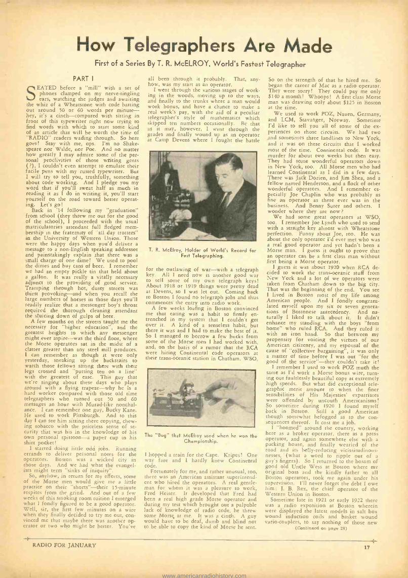
How Telegraphers Are Made First of a Series By T. R. McELROY, World's Fastest Telegrapher
PART I
SEATED before a "mill" with a set of phones clamped on my nerve -tingling ears, watching the judges and awaiting
the whiz of a Wheatstone with code batting out around 50 or 60 words per minute- - hey, its a cinch -compared with sitting in front of this typewriter right now trying to find words with which to start some kind of an article that will be worth the time of "RADIO" readers wading through. So here goes! Stay with me, ops. I'm no Shake- speare nor Wilde, nor Poe. And no matter how greatly I may admire some of the per- sonal proclivities of those writing gents ( ?), I couldn't even attempt to emulate their facile pens with my rusted typewriter. But I will try to tell you, truthfully, something about code working. And I pledge you my word that if you'll sweat half as much in reading it as I do in writing it, you'll start yourself on the road toward better operat- ing. Let's go!
Back in '14 following my "graduation" from school (they threw me out for the good of the school), I proceeded with the usual matriculatories attendant full fledged mem- bership in the fraternity of "all day trotters" in the University of Western Union. Those were the happy days when you'd deliver a message to a non -English speaking addressee and painstakingly explain that there was a small charge of one dime! We used to pool the dimes and buy cans of beer. I remember we had an empty pickle tin that held about a gallon. It was really a vitally necessary adjunct to the providing of good service. Tramping through hot, dusty streets was thirst provoking -and when you recall the large numbers of horses in those days you'll readily realize that a messenger boy's throat required the thorough cleaning attendant the sluicing down of gulps of beer.
A few months on the streets taught me the necessity for "higher education ", and the greatest heights to which any messenger might ever aspire -was the third floor, where the Morse operators sat in the midst of a clatter greater than any steel mill produces. I can remember as though it were only yesterday, sneaking up the backstairs to watch those fellows sitting there with their legs crossed and "putting ten on a line" with the greatest of ease. This guy that we're singing about these days who plays around with a flying trapeze -why he is a hard worker compared with those old time telegraphers who turned out 50 and 60 messages an hour with Murad -like nonchal- ance. I can remember one guy, Bucky Kane. He used to work Pittsburgh. And to this day I can see him sitting there copying, chew- ing tobacco with the priceless sense of se- curity that was his in the knowledge of his own personal spittoon -a paper cup in his shirt pocket!
I started doing little odd jobs. Running errands to deliver personal notes for the operators. Boston was a wicked city in those days. And we had what the evangel- ists might term "sinks of iniquity ".
So, anyhow, in return for my efforts, some of the Morse men would give me a little practice on their "shorts" -their 15- minute respites from the grind. And out of a few weeks of this smoking room tuition I emerged what I fondly figured to be a good operator. Well, sir, the first few minutes on a wire when they finally decided to try me out, con- vinced me that maybe there was another op- erator or two who might be better. You've
all been through it probably. That, any- how, was my start as an operator.
I went through the various stages of work- ing in the woods, moving up to the ways, and finally to the trunks where a man would work bonus, and have a chance to make a real week's pay, with the aid of a peculiar telegrapher's style of mathematics which skipped ten numbers occasionally. Be that as it may, however, I went through the grades and finally wound up as an operator at Camp Devens where I fought the battle
T. R. McElroy, Holder of World's Record for Fast Telegraphing.
for the outlawing of war -with a telegraph key. All I need now is another good war to sell some of my own telegraph keys! About 1918 or 1919 things were pretty dead at Devens, so I was let out. Coming back to Boston I found no telegraph jobs and thus commences the entry into radio work.
A few weeks loafing in Boston convinced me that eating was a habit so firmly en- trenched in my system that I couldn't get over it. A kind of a senseless habit, but there it was and I had to make the best of it. So I managed to borrow a few bucks from some of the Morse men I had worked with, and, on the basis of a rumor that the RCA were hiring Continental code operators at their trans -oceanic station in Chatham, WSO,
The "Bug" that McElroy used when he won the Championship.
I hopped a train for the Cape. Kripes! One way fare and I hardly knew Continental code.
Fortunately for me, and rather unusual, too, there was an American assistant superintend- ent who hired the operators. A real gentle- man for whom it was a pleasure to work, Fred Heiser. It developed that Fred had been a real high grade Morse operator and during my test which brought out a palpable lack of knowledge of radio code, he threw some Morse at me. It was a cinch. A guy would have to be deaf, dumb and blind not to be able to copy the kind of Morse he sent.
So on the strength of that he hired me. So began the career of Mac as a radio operator. They were sorry! They could pay me only $140 a month! Whoops! A first class Morse man was drawing only about $125 in Boston at the time.
We used to work POZ, Nauen, Germany, and LCM, Stavanger, Norway. Sometime I'd like to tell you all of some of the ex- periences on those circuits. We had two and sometimes three landlines to New York, and it was on these circuits that I worked most of the time. Continental code. It was murder for about two weeks but then easy. They had some wonderful operators down in New York, too. All Morse men who had learned Continental as I did in a few days. There was Jack Dorien, and Jim Shea, and a fellow named Henderson, and a flock of other wonderful operators. And I remember es- pecially Joe Chaplin who was probably as fine an operator as there ever was in the business. And Benny Suter and others. I wonder where they are now?
We had some great operators at WSO, too. I remember Joe Lynch who used to send with a straight key almost with Wheatstone perfection. Funny about Joe, too. He was about the only operator I'd ever met who was a real good operator and yet hadn't, been a Morse man. I guess it ought to prove that an operator can be a first class man without first being a Morse operator.
I guess it was about 1920 when RCA de- cided to work the trans- oceanic stuff from New York and a lot of we operators were taken from Chatham down to the big city. That was the beginning of the end. You see I lived in Boston most of my life among American people. And I fondly congratu- lated myself upon my six or seven genera- tions of Bostonese antecedency. And na- turally I liked to talk about it. It didn't enhance my standing with the boys "from home" who ruled RCA. And they ruled it with an iron hand. So that between my propensity for voicing the virtues of our American citizenry, and my espousal of the cause of "collective bargaining ", it was only a matter of time before I was out "for the good of the service" -they couldn't take it!
I remember I used to work POZ much the same as I'd work a Morse bonus wire, turn- ing out faultlessly beautiful copy at extremely high speeds. But what did exceptional tele- graphic merit amount to when the finer sensibilities of His Majesties' expatriates were offended by uncouth Americanisms! So sometime during 1920 1 found myself back in Boston. Still a good American though somewhat befogged as to the con- sequences thereof. It cost me a job.
I "boomed" around the country, working here as a broker operator, there as a press operator, and again somewhere else with a packing house, and finally wearied of the road and its belly- reducing vicissitudinous - nesses, (what a word to ripple out of a guy's fingers). So I returned to the bosom of good old Uncle Wess at Boston where my original boss and the kindly father to all Boston operators, took me again under his supervision. I'll never forget the debt I owe him: J. B. Rex, the chief operator of the Western Union in Boston.
Sometime late in 1921 or early 1922 there was a radio exposition at Boston wherein were displayed the latest models in salt box wound induction coils and basket wound vario- couplers, to say nothing of those new
(Continued on page 28)
RADIO FOR JANUARY 17
www.americanradiohistory.com
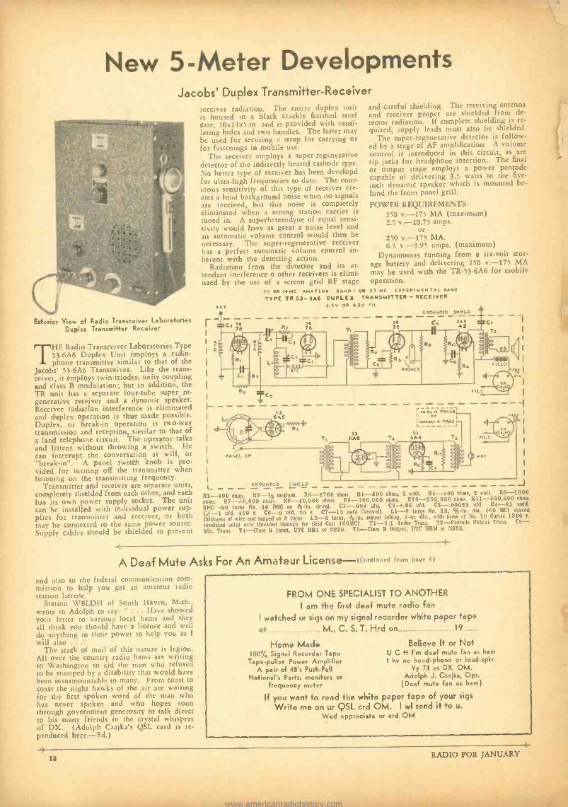
New 5 -Meter Developments Jacobs' Duplex Transmitter- Receiver
Exterior View of Radio Transceiver Laboratories Duplex Transmitter Receiver
THE Radio Transceiver Laboratories Type 53 -6A6 Duplex Unit employs a radio- phone transmitter similar to that of the
Jacobs' 53 -6A6 Transceiver. Like the trans- ceiver, it employs twin -triodes, unity coupling and class B modulation; but in addition, the TR unit has a separate four -tube super re- generative receiver and a dynamic speaker. Receiver radiation interference is eliminated and duplex operation is thus made possible. Duplex, or break -in operation is two -way transmission and reception, similar to that of a land telephone circuit. The operator talks and listens without throwing a switch. He can interrupt the conversation at will, or "break -in ". A panel switch knob is pro- vided for turning off the transmitter when listening on the transmitting frequency.
Transmitter and receiver are separate units, completely shielded from each other, and each has its own power supply socket. The unit can be installed with individual power sup- plies for transmitter and receiver, or both may be connected to the same power source. Supply cables should he shielded to prevent
receiver radiation. The entire duplex unit is housed in a black crackle finished steel case, 10x14x5 -in. and is provided with venti- lating holes and two handles. The latter may be used for securing a strap for carrying or for fastenings in mobile use.
The receiver employs a super- regenerative detector of the indirectly heated cathode type. No better type of receiver has been developd for ultra -high frequencies to date. The enor- mous sensitivity of this type of receiver cre- ates a loud background noise when no signals are received, but this noise is completely eliminated when a strong station carrier is tuned in. A superheterodyne of equal sensi- tivity would have as great a noise level and an automatic volume control would then be necessary. The super -regenerative receiver has a perfect automatic volume control in- herent with the detecting action.
Radiation from the detector and its at- tendant inerference o other receivers is elimi- naed by the use of a screen grid RF stage
and careful shielding. The receiving antenna and receiver proper are shielded from de- tector radiation. If complete shielding is re- quired, supply leads must also be shielded.
The super -regenerative detector is follow- ed by a stage of AF amplification. A volume control is introduced in this circuit, as are tip jacks for headphone insertion. The final or output stage employs a power pentode capable of delivering 3.5 watts to the five -
inch dynamic speaker which is mounted be- hind the front panel grill.
POWER REQUIREMENTS: 250 v. -175 MA (maximum) 2.5 v. -10.75 amps.
or 250 v. -175 MA. 6.3 v. -3.95 amps. (maximum)
Dynamotors running from a six -volt stor- age battery and delivering 250 v.-175 MA may be used with the TR- 53 -6A6 for mobile operation.
26 OR 56MC AMATEUR BAND- OR 37 MC EXPERIMENTAL BAND
TYPE TR 53 -6A6 DUPLEX TRANSMITTER - RECEIVER 2.5V OR 6.3v riL
56
GROUNDED SHIELD
56 C2 2A5 CI 76 42
T2
^
I-
L R1 -400 ohms. R2 -% meghom. R3 -2700 ohms. R4 -500 ohms, 2 watt. R5 -500 ohms, 2 watt. R6 -1000 ohms. R7- 50,000 ohms. RS- 40,000 ohms. R9- 100,000 ohms. R10- 250,000 ohms. R11- 500,000 ohms.
RFC -50 turns No. 30 DSC on {yl -in. dowel. C1 -.004 ofd. C2 -.05 acrd. C3- .00025 ufd. C4 -35 Hurd.
C5 -1 ufd, 450 T. C6 -5 ufd, 25 R. C7 -15 mad Cardwell. L1 -9 turns No. 12, % -in. dia. (60 MC) spaced
thickness of wire and tapped at G turns. L2 -2 turns, ÿs -in. copper tubing, 2 -in. dia., with piece of No. 19 Corlac 1300 r.
insulated solid wire threaded through for Grid Coil (60h1C). T1 -3:1 Audio Trans. T2- Pentode Output Trans. T3- Mk. Trans. T4 -Class B Input, UTC HB1 or NS29. T5 -Class B Output, UTC 1IBM or NS33.
5
53 6A6 -r
r,R TR6AÉ, on
um(YTS TR63i
53 6A6
GROUNDED SHIELD
A Deaf Mute Asks For An Amateur License -,Continued from page 6)
and also to the federal communication com- mission to help you get an amateur radio station license."
Station W8LDH of South Haven, Mich.. wrote to Adolph to say: " . Have showed your letter to various local hams and they all think you should have a license and will do anything in their power to help you as I
will also ..." The stack of mail of this nature is legion.
All over the country radio hams are writing to Washington to aid the man who refused to be stumped by a disability that would have been insurmountable to many. From coast to coast the night hawks of the air are waiting for the first spoken word of the man who has never spoken and who hopes soon through government generosity to talk direct to his many friends in the crystal whispers of DX. (Adolph Czajka's QSL card is re- produced here. -Ed.)
4-
FROM ONE SPECIALIST TO ANOTHER
I am the first deaf mute radio fan
I watched ur sigs on my signal recorder white paper tape
at M., C. S. T. Hrd on 19
Home Made 100% Signal Recorder Tape
Tape -puller Power Amplifier A pair of 45's Push -Pull
National's Parts. monitors or frequency meter
U C I hv
Believe It or Not it I'm deaf mute fan as ham no head -phone or loud -spkr.
Vy 73 es DX. OM. Adolph J. Czajka, Opr.
(Deaf mute fan es ham)
If you want to read the white paper tape of your sigs
Write me on ur QSL crd OM. I wl send it to u.
Wud appreciate ur crd OM
4--
18 RADIO FOR JANUARY
www.americanradiohistory.com
AMATEUR NEWS Largest Amateur Gathering To Be Staged in San Francisco
ATWO -DAY amateur conclave and high -frequency radio show will be staged by the Federation of Radio
Clubs of Northern California, a newly - formed association which comprises the more important radio clubs. The purpose of the Federation is to promote better conven- tions and hamfests and to enable the radio clubs of the entire northern portion of the state to more effectively work together.
New innovations in hamfests are promised when the amateurs of Northern California convene on February 23rd. The affait will close on February 24th. There will be a series of contests to determine the best de-
'r :l lkll'Cl l.l.',1;1-L'-Ll:l,l;l'lC
., The Prize Drawing"
-or "After the Raffle Was Over"
signed and constructed pieces of radio equip- ment; there will be contests for fixed and mobile 5 -meter equipment, receiver and transmitter contests. All amateurs are invited to bring their special pieces of equipment. A large number of prizes will be awarded, the total value of which will exceed one thousand dollars. Many of the more val- uable prizes will be awarded to those who win the various equipment construction and design contests.
Another of the innovations is the manner in which the prizes will be obtained. The donors of the prizes will be given a pro - rata refund of 75 per cent of the total net receipts. It is hoped that this refund will be ample to reimburse the donors for the actual cost of the prizes.
The registration fee is $1.50, which in- cludes the banquet ticket. Many of the bet- ter prizes will be reserved for those who send in their moneys previous to the open- ing of the conclave.
There will also be a 5 -meter hidden trans- mitter hunt. Many new pieces of equipment will be demonstrated and all of the new receivers will be in action. Hotel rooms have been reserved for the prominent re- ceiver manufacturers. Provisions have been made to install effective antenna systems so that all equipment can be demonstrated to best advantage.
There will he a "round robin" technical meeting. Ir will be a clearing house for questions asked by the audience. These ques-
tions will be answered by a group of more than ten well known technical men.
PROGRAM Registration, 9 AM Saturday, February
23rd. 9 to 12 AM, trip to Tropical Beach, Sutro Baths.
1 to 5 PM, Technical Round Robin. Chair- man, W6CAL. Speakers (15 minutes each), Charles Perrine, Jr., W6CUH; Al O'Neil, W6GIS; George Becker; Ralph M. Heintz, W6XBB; Clayton F. Bane, W6WB; Frank C. Jones, W6AJF; John L. Stevens, W6PW; W. W. Smith, W6BCX; J. A. McCullough, W6CHE; Charles Watson, W6DW; J. N. A. Hawkins, W6AAR.
7:30 PM, meeting of delegates of Feder- ated Radio Clubs of Northern California. Visitors welcome.
7 :45 PM, political meeting. Sunday, February 24th
9 to 12 AM, Hidden 5 -meter transmitter hunt and receiver demonstrations in hotel rooms.
1:30 to 3:30 PM, Two feature speakers. 3:30 to 5:30 PM, Amateur -built equip-
ment contest. 7:00 PM, Banquet, entertainment and
prize drawing. Advance registration fees should be sent
to W6JAL, Arthur Holmes, Secretary, 431 Lincoln Way, San Francisco, California. Ar- rangements have been made to accommodate 900 amateurs. Reduced hotel rates will be in effect. YLs and YFs are cordially invited.
From Emil Guidici at Sheepranch, California. comes word that ZS2A. South Africa. will be off the air indenitely due to the passing of his mother. The amateur fraternity extends deep sympathy to ZS2A.
W 7 CFJ H. P. Rosh', 307 16th Ave., Seattle, Washington, wants the QRA of OA4AI in Peru. He worked this station on February 24, 1934, but can't find the QRA. If any reader knows the whereabouts of OA4AI, he is kindly requested to communicate with W7CFJ.
Australian amateurs have a few ten meter (and five) enthusiasts among their number, and a con- stant watch has been kept on ten for three or four years by one or two. As this time of the year produces the best results on this band, activity has been increasing during the past week -ends.
Sunday, 25/11/34, proved to be exceptional. In Sydney, VK2LZ, 2HZ. 2NO and 2YC were on the air from 9 AM. VK4BB in Maryborough and VK4XN started to romp in and were speedily QSO'd by the VK2 gang. Whilst VK2NO was QSO VK4BB, the latter suddenly broke off and started calling ZLIBA. He hooked the ZL and subsequently told me that the reason was because the ZL's signal swept across the band in the process of tuning at QSA5 R8. VK4BB followed the signal to see who he was and nearly fell off his perch when he found it was a Maorilander. This was exciting because we have been looking for ZL's on ten for a long weary period. Shortly
after this, VK6SA in Perth, 2000 miles across Australia, began to come through at good strength and the two VK4's landed him. The chief inter- est at VK2NO was that just after this, K6EWQ's harmonic was heard at QSA4 R4 calling CQ and subsequently working an LU7. This was at 11 AM our time. It was only when K6EWQ started working the LU that I realized it was a harmonic. Surely this shows that conditions are becoming favorable for trans -Pacific working again on ten VK4BB and 4XN had a great day. They worked several VK2's l's and 6's. This kind of thing hasn't happened since 1928. In December. Janu- ary and February, a VK-ZL ten -meter contest is running. Here is an opportunity for your ten - meter exponents on the West Coast to look for us. The contest will be confined to the Sundays, our time. and will run from 8 AM to 8 PM. VK4BB has also heard J2IS on ten, so things are looking up.
All good wishes, Don B. Knock,
Radio Editor, "The Bulletin" (VK2NO -2NU)
I . R. F. NEWS NEW IRF MEMBERS: K7BND, W6ITH, W6CSX, W6RH, W6ICX, W6JWL, W6GVS, VE5EO, and VE5FH. We wish you many IRF QSOs!
If you know of any YL operators, whom you think can qualify for IRF, we would like to get them pledged.. It may interest the general membership to know the YL mem- bers of IRF to date:
W7AHJ- Esther Brunk VE5KS -May Rose Sparks W6EK -Flora Card W6DHV -Mae Amarantes W5BKV -Sally Walker W7NH- Nellie Hart W9LW -Lucia Mida W6HEG- Harriett Gilbert W6AET- Florence Jones
New Division Chief W1BZC, William Ellsworth, has been the
Division Chief for the East Coast Division in the past, but has changed his QRA from Massachusetts down to Pennsylvania, and is now in the Capitol Division. Dr. John A. Stewart, WISK, has very kindly accepted to succeed Mr. Ellsworth in the position of Chief for the East Coast Division. We wish him luck, as they have a fine Division of fine men.
Eastern News W8ELO: "Heartily in favor of east coast
gang get -togethers as suggested in last LJ." W2CJP says, "Rehabilitation plan is FB, and it will be the biggest publicity stunt ever pulled for Amateur Radio." His frequency is 3547 KC.
5 -Meter QRM Problem Solved!
Fariner "Jinks" and his good horse, "Janu- ary", have solved the perplexing problem of automobile ignition QRM on 5 meters. If you are troubled with auto noise, or if the 5 -meter band in the big cities is overcrowded, do as the good farmer does. The radio in- spector will then have an ell of a time finding your QRA.
RADIO FOR JANUARY 19
www.americanradiohistory.com
The Evolution Of A Vacuum Tube
S ALES Manager of Novacex Inc. informs Chief Engineer that what the hams need is an addition to the Novacex line of
elèctronic devices that will fill the gap be- tween the NG -210 and NG -211 transmitting tubes. Chief Engineer stays up all night try- ing to decide whether to first build the tube and then name it, or to name the tube and then build it. After going into conterence with second pint of Old Crowf gets inspira- tion to call new tube the NG- 2101/2. Office boy remarks that designation is very fitting, but reminds C -E that Feebeltron has a tube called the FB- 4791/2, and confusion might therefore arise because they sound so much alike. Suggests to C -E that they call the rube the NG -73.
For rough draft of proposed tube, design department uses pantograph on drawing of NG -210, and brings plate lead out top of envelope.
Office boy takes home first experimental model of tube and reports after trying it in his TNT that the thing got "pretty red" with 93 watts input and the key held down. Chief had a TNT once, and found efficiency to be 47 per cent, so with 93 watts input the tube must have been dissipating 50 watts, he figures. Office boy discloses that his milli - ammeter has bad habit of sticking and get- ting loggy; therefore figure of 93 watts should not be taken too seriously. C -E re- plies not to worry about that, because he was not sure of the accuracy of the ratings on the carbon lamps he used for dummy load, and only guessed at normal brilliancy anyhow. So maybe a TNT was 69 per cent efficient instead of 47 per cent.
Janitor asks C -E why he doesn't run static test on the tube to determine how much it will dissipate without getting too red, in- stead of fussing around wih TNTs. C -E shuts him up by giving him second experimental tube to take home with him to play with, and then rushes off to lab to see about the matter of static inputs. Janitor reports next morning that tube gets fairly blue at 1250 volts.
Advertising department releases advance data on new NG -73 along with tentative rat- ings: Plate dissipation (max.) 50 watts. Plate voltage (max.) 1250. Oversupply of 210 fila- ment stock results in tube having 11/4 amp. filament, 15 volts to give necessary watts emission. Shop foreman's son reports that he had 1500 volts on one for 5 minutes and it didn't blow up or go soft, so rating is changed to read 1500 maximum plate volts.
Charlie Perrine writes in and says that he obtained 231 warts output from an NG -73, with a note that if grid lead were brought out side so a 203 -A driver could be used without the NG -73 flashing in the base, and the tube were pumped harder to allow 2800 volts on the plate instead of the 2200 he was using, it would be possible to get 239 watts output without exceeding the dis- sipation rating. Chief Engineer after reading letter five times announces that he has, after much scientific research, decided to scrap current design and change mechanical con- struction. He carries the idea one step fur- ther and brings not only the grid lead out the side, but also the filament leads out the other side. Notices that pins on base are not connected to anything, so decides to
See August 1934 QST. t An old favorite of both receiver and vacuum
tube manufacturers.
(With Apologies to W6AAR)*
By W. W. SMITH, W6BCX Associate Editor, Rí9
throw hase away. Discovers difficulty of mounting tube which has no prongs, so de- cides to put base back on.
Remembers about remark that tube should he pumped harder. Makes memo to put more "getter" in the tubes and increase the size of the envelope to allow cool spot of glass at bottom of tube for gases to collect on. President sends him memo never to use a preposition to end a sentence with.
Tube now handles 2800 volts without cel- ebrating Fourth of July. Assistant Engineer notes new size of envelope and remarks that it is now large enough that if cooling flanges were put on the plate, the dissipation rating could be raised to 75 watts. "Improved" NG -73 makes its debut, sporting new cor- rugated- carbonated plate with cooling flanges giving the anode the appearance of a burned drug -store waffle wearing flippers. Data sheet states 300 watts input now permissible in high -efficiency circuits.
Skroo Loos, W5NUT, takes antenna off his Perrine rig to show visitors how he can draw off a 7 -inch arc, and blows NG -73 through roof. Writes to factory saying tube sure enough "NG" all right, and asks why bother to put the 'ex" on "Novacex "? Does not think it necessary to mention small mat- ter of plate voltage of 3200 and removal of antenna.
W6AM writes in that tube gets very hot with 300 watts input, which should be per- missible according to ratings. Does not no- tice that he has mixed up coils on trick Don Wallop coil -changing scheme and is using 20 meter coil on 40 (resulting in very high "C "), as he has become far -sighted from trying to point out to visitors the trade mark on "Q" antenna atop his new tower.
W4SOS writes in plate ready to melt at 250 watts input, but neglects to mention that tube was running self -excited on 1% meters. After mailing letter finds that the tube wasn't on 11 /, meters after all, because the tube wasn't even oscillating. Decides to keen dis- covery to himself and lets letter ride.
W7RAZ forgets to remove shunt from milliammeter, and writes very derogatory letter about tube being over- rated. Visiting ham notices shunt and calls it to his atten- tion, but RAZ remarks that the tube prob- ably isn't any good anyhow, and that even if it were good he wouldn't like it.
Adjustment department gets tired of re- placing tubes and answering complaints, so advises engineering department to make the tube huskier so that the hams can run 300 watts input, and not just 300 Perrine watts input.
Plate is made larger to handle more heat, and spacing is increased to raise breakdown and keep interelectrode capacity at approxi- mate rated vlue. Proving laboratory finds tube okay except plate resistance now twice original value, which is corrected by putting in a huskier filament, now drawing 4 amps. instead of 11/4 amps at the same 15 volts.
News leaks in through grapevine that Feebeltron is about to release a tube with a mutual conductance of 9237 as compared to 3879 mmhos. for the NG -73. Chief decides that too much plate is hiding from the fila- ment. Designs phantom grid structure to cut down shadow and raise mutual conductance. Research department brings in tube in which
no grid can be seen at all. C -E compliments research department, and then notes they car- ried things a bit too far by leaving out grid altogether. New Novacex high voltage recti- fier for cathode ray equipment announced; appearance is suspiciously similar to the NG -73.
Chief decides to quit playing with ghosts and leave grid structure as originally planned, and to raise mutual conductance by putting in still more filament. New 8 ampere filament radiates so much heat that envelope melts with no palte input. Envelope glass changed to Stonex.
President's son decides to build himself a ham rig using low level modulation with a pair of NG -73s as linear amplifier. Because of comparatively low efficiency, finds that output is limited by plate dissipation long before maximum allowable plate voltage and plate current are reached. Instructs dad to instruct C -E to put flanges on the cooling flanges to increase dissipation rating. New NG -73 is announced, more suited to low - level and grid- modulation as dissipation rating has been raised from 135 to 165 watts, without change in other characteristics.
Letter from Perrine states that at 4600 volts he finds it possible to run 2800 watts input to a single NG -73§ without the plate getting much more than a vivid red if keyed with light enough dots.
Engineering staff compliments itself on new tube, and celebrates occasion by opening case of Old Crow. President opens letter from field man advising him that what the hams need is a tube that will fill the gap between the NG -210 and NG -211. President has idea for new tube. Chief Engineer has delirium tremens.
II As measured in a dummy antenna. -Editor. - --
This R -S -T System THE readibility, audibility and tone sys-
tem now used is the standard of the world, and has worked out very well.
In fact, almost everyone is well satisfied with its meaning, except the A.A.R.S. and N.C.R. stations who have been using a S -1 to S -5 scale. All have learned to give cor- rect reports by the QSA system, so why change to the R -S -T method?
In the October QST, W2BSR outlined a new system, which has been approved by the ARRL and is in use at vV1MK.
In a letter received from Mr. Handy, Com- munication Manager of the League, he says: "THE OSA SYSTEM l,S PART OF THE SUPPLEMENTARY REGULATIONS (MA- DRID CONVENTION) AND WILL AL- WAYS BE IN USE INTERNATIONALLY, UNLESS CHANGED AT FORTHCOMING CONVENTIONS (CAIRO). THE R -SYS- TEM IS WELL KNOWN, AND HAS EARNED HIGH AMATEUR REGARD."
In this case why does the ARRL try to start something new like this when, in the first place, they are encouraging the ham to break international laws in addition to get- ting the ham all muddled up with just an- other regulation?
I suggested that the signal strength por- tion of the R -S -T system be raised to 9, but Mr. Handy says this would involve very wide confusion at this time. Funny thing that he never thought of a "very wide con- fusion" when the League adopted the R -S -T system.
(Continued on page 32)
20 RADIO FOR JANUARY
www.americanradiohistory.com

Here is a thriller, if ever there was one. Picture yourself in a lighthouse on the ocean. A storm breaks ... your entire radio station is destroyed. What would you do to effect radio communication with the mainland? The Inter- ceptor has intercepted a letter from F. L. Black, one of Oregon's SCMs, and attached to the SCM's letter was the thrilling story of how Henry Jenkins, first assistant Lighthouse Keeper of the Tillamook Rock Light off the Oregon coast, suc- ceeded in building an entire amateur trans- mitter and receiver from salvaged pieces of junk -put the rig into operation and effected communication with nearby amateur stations. The Intercepter considers himself fortunate in receiving this thriller from F. L. Black and he hopes that all amateurs will profit from the read- ing of it.
This record begins with the violent storm alas swept the north Pacific, causing severe damage to the Light Station on Tillamook Rock on the 21st of October, 1934. At 10 P.M. October 20th, a fresh southeast wind was blowing with light rain. During the night the wind increased to gale force and changed to the southwest. About 3 AM October 21st the seas ran extremely high, swells hitting base of the rock from the southwest and the spray coming over the rock. At 9:30 AM I was awakened with a sudden jar, completely covered with water. All my clothes and bedding were soaked. The seas at this time were washing over the entire tower, pounding against the window shutters of my room. The window catch let go and the entire room was flooded. At this time the wind was blowing at an estimated 100 miles per hour or more, seas covering the Light- house, carrying with it large rocks, debris and fish which were smashed through the lantern plate glass, breaking 16 panes and flooding all quarters. In endeavoring to re- place glass panes with emergency wooden shutters, Hugo Hanson's right hand was deeply cut. While assisting dressing his wound, I read the barometer which was 28:92 inches. Each time the tons of water would cover the building, coming down with ter- rific impact on the roof, the barometer would drop immediately to 28:72 inches, returning as soon as the impact was over.
Impacts from tons of water and rocks would occur most every three seconds, last- ing from about 10 AM to 12 noon. Prior to that time they were not so frequent. About 10:15 AM a terrific impact occurred and the tower and building were enveloped with giant seas. The large 80 -foot derrick and telephone cable had been swept away.
A 6 -foot section of the west end of the rock was carried away, hurling rocks weigh- ing as much as 50 pounds through tower and on the roof, smashing shutters which were made of 1/2-inch wood. The shutters at the base of the b iilding were carried away, flooding all floors, breaking the piping of
the heating system and thereby cutting -off the heat which was badly needed at this time. We were all soaked, walking in cold water and extremely tired. The lantern and fog signal were now inoperative. Both of these were greatly needed by mariners. We had no other means of warning them. If we put out a different light, and if they would come up close enough to identify it, the conse- quences might have been disastrous. Never - theless, a fixed white light was set up and a crude short -wave transmitter and receiver were built from parts of an old Atwater Kent broadcast receiver on hand at the station. We also had some batteries, scraps of tinfoil, copper and brass.
At 6:50 PM, October 23rd, I made the first call for W7CXK and was picked up by a Portland amateur, Merrill Peoples, W7WR, who was QSO W7CXK and who notified Henry Goetze, W7CXK, that someone was calling him. W7WR could not tell who was calling, because the signals were so weak and chirpy. A message informing the superinten- dent of the damage incurred was the first traffic handled.
When things around here got half dry, I immediately got two boards approximately 10 by 12 inches. Not having any tube sock- ets, I drilled holes in each board for sockets and took the two 30 type tubes out of the BC set and soldered leads on the prongs of the tubes.
On the transmitter board I placed a tank inductance which I made from some Bell transformer wire. The wire was wound on the cardboard case of a No. 6 "A" battery. I used 14 turns. The tuning condenser was a 3 -gang condenser taken from the BC set, but I only used the middle section. I made the series fixed condensers for the antenna out of tinfoil and wax paper in which a loaf of bread had been wrapped. I used no grid condenser or leak. The plate blocking con- denser was "swiped" from the BC set. I made the RF choke from one of the regular BC chokes by removing some turns. This junk, when finally assembled, completed a TNT circuit but used no grid condenser or leak. I took the batteries from the telephone and used them for lighting the filaments. Two No. 6 cells were connected in series. The three "B" batteries from the BC receiver were down to 80 volts. For a key I simply broke the battery connection with my hand. Later I found a piece of spring brass and made a hand key. I sent my first four mes- sages with my fingers breaking the connec- tion on the "B" batteries. But after that I used the home -made hand key. My trans- mitter antenna consisted of 40 feet of sal- vaged wire that was left from the BC set.
Not having anything to work with, the receiver was a crude affair. For the coil I found an old regular telephone receiver and I used the shell as the form on which I wound the 80 -meter band coil. I used 45 turns of wire which I swiped from BC set. This made the grid coil. There were 20 turns on the plate coil. I had no means of controlling oscillation, so I put enough plate turns on the coil to keep it oscillating at all times. For the antenna series condenser I simply twisted two feet of insulated wire together and the capacity of the separation by the insulation served as the series condenser, be- tween the grid coil and the antenna.
I used tinfoil condenser for the grid con- denser, but I used no grid leak. The tuning condenser was made from two brass plates that I removed from the door knob. I fast- ened one plate on the receiver base and the other was separated by a piece of wax wrap. ping paper. Tuning was accomplished by shoving one plate over the other with a pencil. The values of these parts were un- knowh, but due to my past experience I finally found the 80 -meter band and the first
station I heard was W7RT in Seattle. Then I knew where I was, and I immediately tuned with the aid of a pencil. I found W7CXK working W7WR, so I left the receiver tuned on W7CXK and while he was transmitting I tuned my transmitter to his frequency by listening to him with my transmitter oscil- lating. At 6:30 PM October 23, I called W7CXK. W7WR informed W7CXK that someone was calling him, so that was the way QSO was made with the mainland and God's country. Shipping was warned through notifying the Superintendent of Lighthouses by sending message to Goetze, W7CXK, who relayed them to the superintendent at Port- land via Western Union.
(Editor's Tote -Box 215, Seaside, Oregon, is the address of Henry Jenkins, the man who w-rote this story.)
The 222 Communications Receiver (Continued from page 16)
while, since it allows adjustment of the resonant antenna coupling so as to obtain optimum value of first detector regeneration. It can be used with any type of antenna and the latter may be tuned to resonance extern- ally and the optimum coupling easily found. The results were very gratifying. The image interference on 40 meters measured 60 DB units down in level from the desired signal, using a signal generator for these measure- ments. 60 DB means an image rejectivity of 1000 -to -1, which is extremely good for sets using a good stage of RF. The image measured 50 DB down on 20 meters, which is more than most superheterodyne receivers can even approach at that wavelength. The receiver has practically no image whistles of "phantom" commercial signals in the ama- teur bands, unless the commercial signal is of very high field intensity. The signal genera- tor gave an audible signal in the headset with an input of 130 DB down from 1 volt, which is less than one microvolt input. This is ample sensitivity, with low internal re- ceiver noise level, to reach down into the at- mospheric noise level in any locality.
The receiver was built into a metal cabi- net measuring 81/2 inches deep, 7 inches high, and 11 inches long. The front panel is 7 inches x 11 inches of No. 12 gauge alumi- num. The chassis is also of No. 12 ga. alumi- num, bent in the form of a U, two inches deep and 8% inches wide by 10 inches long. All of the necessary tube socket and dial holes can be punched, or cut out with a circle cutter and drill press. The shield partition between the oscillator and detector is also of No. 12 gauge aluminum, 7 inches long, 4% inches high with a % -inch lip along the bottom for fastening to the chassis with 3 machine screws. In building this set it is a good plan to take all of the larger parts and set them on the chassis so as to get the proper chassis layout before drilling. The pictures of this set and the plan drawings should enable anyone to duplicate it with- out trouble. The lower knobs on the front panel from left to right are sensitivity, regen- eration, audio volume, tone control and BFO switch combination, and antenna coupling. The upper row: oscillator band setting ad- justment with knob and small 0 -100 metal escutcheon plate, main tuning control, and last, the detector band setting control and 0 -100 division plate. The antenna leads, power cable plug and telephone jack are at the rear of the chassis with large holes around them through the metal cabinet. The cabinet has a hinged lid.
The receiver is simple in its circuit and easily built. It can be, and was, in this case, built and put on the air in two day's time. The circuit line -up is simple if a modulated oscillator is available for lining up the IF amplifier. If not, it can be aligned by using the noise level from a large antenna.
RADIO FOR JANUARY 21
www.americanradiohistory.com
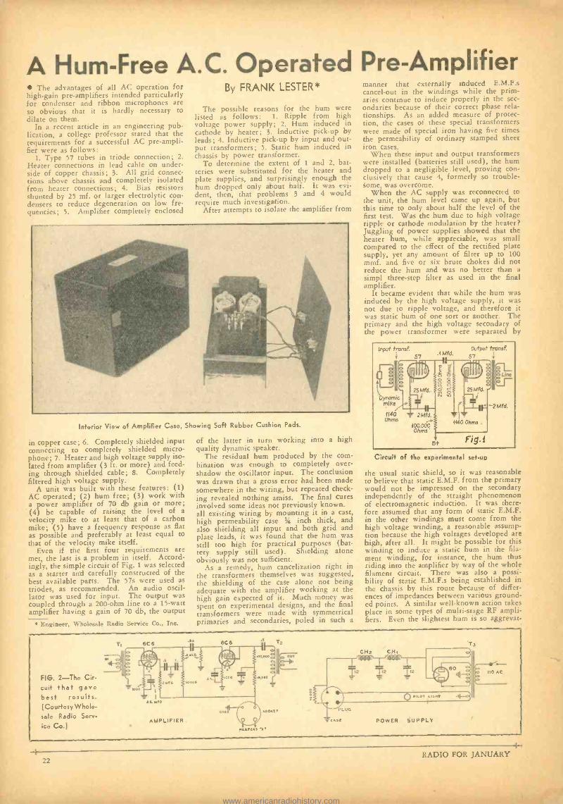
A Hum-Free A.C. Operated Pre -Amplifier The advantages of all AC operation for
high -gain pre -amplifiers intended particularly for condenser and ribbon microphones are so obvious that it is hardly necessary to dilate on them.
In a recent article in an engineering pub- lication, a college professor stated that the requirements for a successful AC pre- ampli- fier were as follows:
1. Type 57 tubes in triode connection; 2.
Heater connections in lead cable on under- side of copper chassis; 3. All grid connec- tions above chassis and completely isolated from heater connections; 4. Bias resistors shunted by 25 mf. or larger electrolytic con- densers to reduce degeneration on low fre- quencies; S. Amplifier completely enclosed
By FRANK LESTER*
The possible reasons for the hum were listed as follows: 1. Ripple from high voltage power supply; 2. Hum induced in cathode by heater; 3. Inductive pick -up by leads; 4. Inductive pick -up by input and out- put transformers; 5. Static hum induced in chassis by power transformer.
To determine the extent of 1 and 2, bat- teries were substituted for the heater and plate supplies, and surprisingly enough the hum dropped only about half. It was evi- dent, then, that problems 3 and 4 would require much investigation.
After attempts to isolate the amplifier from
Inferior View of Amplifier Case,
in copper case; 6. Completely shielded input connecting to completely shielded micro- phone; 7. Heater and high voltage supply iso- lated from amplifier (3 ft. or more) and feed- ing through shielded cable; S. Completely filtered high voltage supply.
A unit was built with these features: (1) AC operated; (2) hum free; (3) work with a power amplifier of 70 db gain or more; (4) be capable of raising the level of a
velocity mike to at least that of a carbon mike; (5) have a frequency response as flat as possible and preferably at least equal to that of the velocity mike itself.
Even if the first four requirements are met, the last is a problem in itself. Accord- ingly, the simple circuit of Fig. 1 was selected as a starter and carefully constructed of the best available parts. The 57s were used as triodes, as recommended. An audio oscil- lator was used for input. The output was coupled through a 200 -ohm line to a 15 -watt amplifier having a gain of 70 db, the output
Engineer, Wholesale Radio Service Co., Inc.
Showing Soft Rubber Cushion Pads.
of the latter in turn working into a high quality dynamic speaker.
The residual hum produced by the corn - bination was enough to completely over- shadow the oscillator input. The conclusion was drawn that a gross error had been made somewhere in the wiring, but repeated check- ing revealed nothing amiss. The final cures involved some ideas not previously known. all existing wiring by mounting it in a cast, high permeability case 14, inch thick, and also shielding all input and both grid and plate leads, it was found that the hum was still too high for practical purposes (bat- tery supply still used). Shielding alone obviously was not sufficient.
As a remedy, hum cancelization right in the transformers themselves was suggested, the shielding of the case alone not being adequate with the amplifier working at the high gain expected of it. Much money was spent on experimental designs, and the final transformers were made with symmetrical primaries and secondaries, poled in such a
manner that externally induced E.M.F.s cancel -out in the windings while the prim- aries continue to induce properly in the sec- ondaries because of their correct phase rela- tionships. As an added measure of protec- tion, the cases of these special transformers were made of special iron having five times the permeability of ordinary stamped sheet iron cases.
When these input and output transformers were installed (batteries still used), the hum dropped to a negligible level, proving con- clusively that cause 4, formerly so trouble- some, was overcome.
When the AC supply was reconnected to the unit, the hum level came up again, but this time to only about half the level of the first test. Was the hum due to high voltage ripple or cathode modulation by the heater? Juggling of power supplies showed that the heater hum, while appreciable, was small compared to the effect of the rectified plate supply, yet any amount of filter up to 100 mmf. and five or six brute chokes did not reduce the hum and was no better than a
simpl three -step filter as used in the final amplifier.
It became evident that while the hum was induced by the high voltage supply, it was not due to ripple voltage, and therefore it was static hum of one sort or another. The primary and the high voltage secondary of the power transformer were separated by
input tronsf. Output tronsf. .1 Mfd. 57 ¡ 57
É O Ine
c"1i
Dynam'c mike
25 Mfd. O Ó o ó ti n
25 Mfd.
-2 Mfd.
1140 2 Mfd. Ohms 1140 Ohms
100,000 Ohms'
B+ Fig i
Circuit of the experimental set -up
the usual static shield, so it was reasonable to believe that static E.M.F. from the primary would not be impressed on the secondary independently of the straight phenomenon of electromagnetic induction. It was there- fore assumed that any form of static E.M.F. in the other windings must come from the high voltage winding, a reasonable assump- tion because the high voltages developed are high, after all. It might be possible for this winding to induce a static hum in the fila- ment winding, for instance, the hum thus riding into the amplifier by way of the whole filament circuit. There was also a possi- bility of static E.M.F.s being established in the chassis by this route because of differ- ences of impedances between various ground- ed points. A similar well -known action takes place in some types of multi -stage RF ampli- fiers. Even the slightest hum is so aggrevat-
FIG. 2 -The Cir-
cuit that gave best results. (Courtesy Whole- sale Radio Serv-
ice Co.)
CH2 CHi T3
POWER SUPPLY
Ile AC
22 RADIO FOR JANUARY
www.americanradiohistory.com
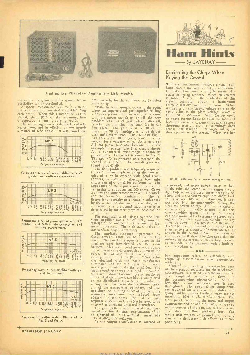
Front and Rear Views of the Amplifier in its Metal Housing.
ing with a high -gain amplifier system that no possibility can be overlooked.
A special transformer was made with all the windings electrostatically shielded from each other. When this transformer was in- stalled, about 90% of the remaining hum disappeared -a most gratifying result.
The remaining hum was definitely cathode - heater hum, and its elimination was merely a matter of tube choice. It was found that
afro c +5
r 5 ñ to
1111iii1111 Ila1111 1111111a 1111111a1111 I11111I0-::!!!! Illlllla1111 1!:111111I11111a11ìl11 Ila1111 111111 a11111IIa111G!1a1111 11111111111111inM1111n1=1111
ñ í9i óó $8ó8ó$ 82588 nq ö öE 25 N no ,00r
Frequency response
Frequency curve of pre -amplifier with 79 triodes and ordinary transformers.
ó tlo
c gs to
IIIIIla11Illia1111 IlllllaII-_ 1111H a111 l::iiiiimumilimÀti! a111 111III111111I1111 (Nee 1 IlllllaIllllllaIllllil espansron)il
8 $88 88$8$ PAM EH! H na 6 N ri e Frequency response
Frequency curve of pre -amplifier with 6C6 pentode and 6C6 triode connection, and
ordinary transformers.
ó +5 0
-5
11un1M11111= Inn1111111 111i11111IIffir1 111111I11111IIII 111n11a111Afiliï111111 aIIII íillna1111111a1111maii:a :: 111111aIllnll1111111 11111111111111111n11 (Note
8 $ 48 U3,&§§§ Frequency response
Frequency curve of pre -amplifier with spe- cial transformers.
m 0 c +5
.4.s
lliiiiaIllillia1111111111i 11111 lal'I lllHla1 11
IIII 1___ nn1a111111 :1Illil1111ina111111Iai:.I IlillliitInilliiaIlliiii (Neh 11 I111111111111 a1111111 eapans+an
88 88$$ 1.1 Pl!$ Frequency response
Response of entire system illustrated in Fig. 3 and Fig. 4.
6C6s were by far the quqietest, the 57 being quite noisy.
With the hum brought down to the point where an experimental pre -amplifier feeding a 15 -watt power amplifier was just as quiet with the power switch on or off, the next problem was that of gain, which, after all, is what the amplifier was built for in the first place. The gain must be 40 db or more if a 70 db amplifier is to be driven with sufficient reserve. The circuit of Fig. 1
had only about 38 db gain, which was not enough for a velocity mike. An extra stage did not prove successful because of terrific microphone effects. The final circuit chosen for a commercial wide -range high- fidelity pre -amplifier (Lafayette) is shown in Fig. 2. The first 6C6 is operated as a pentode, the second as a triode. The overall gain was found to be 62 db.
The final problem was frequency response. Curve 1, of an amplifier using the two tri- odes of a 79 in cascade with good trans- formers, is shown to illustrate how tube choice can affect amplifier performance. The impedance of the input transformer second- ary in this case is about 100,000 ohms. Curve 2 shows the same transformer with a pentode and pentode- triode combination. The re- flected input capacity of a triode is influenced by the mutual conductance of the tube; with a pentode it is the actual input capacity as determined by the mere physical construction of the tube.
The practicability of using a pentode first - stage amplifier was a bit of luck, from the standpoint of microphonics as well as fre- quency response. The high gain makes an intermediate stage unnecessary.
The amplifier response represented by Curve 2 was still not ideal for a high fidelity mike. The possible frequency losses in the amplifier were investigated, and the trans- formers under ideal conditions were found not to possess the discrepencies shown in the curve. It was also found that a response varying only 1 db from 30 to 17,000 cycles was obtained with the input transformer eliminated and the test input fed directly to the grid circuit of the first amplifier. The input transformer was then held responsible, but since it showed no such loss as mentioned under ideal conditions. the blame was placed on the distributed capacity of the tube, its wiring, etc. To lower the distributed capa- city of the transformer secondary, and also to reduce the shunting effect of the tube, the secondary impedance was reduced from 100,000 to 40,000 ohms. The final frequency response as shown in Curve 3 is believed to be as good as anything obtained heretofore.
The gain suffers with reduced secondary impedance, but the final amplification of 56 db (instead of 62 as originally measured) proved altogether sufficient.
As the output transformer is worked at
Ham Hints - By JAYENAY
Eliminating the Chirps When Keying the Crystal
In the conventional pentode crystal oscil- lator circuit the screen voltage is obtained from the plate power supply by means of a series dropping resistor. When an attempt is made to key in the center -tap of this crystal oscillator circuit, a bothersome chirp is usually found in the note. When the key is up the screen voltage rises to the same value as the plate voltage, which is from 350 to 450 volts. With the key open, no space current flows through the tube and because there is no current through the screen dropping resistor, there is no voltage drop across that resistor. The high voltage is thus applied to the screen. When the key
47
R- soot) -10,000o.w, trocs ..o ,oa.o1.s ON 'LIKEN)
is pressed, and space current starts to flow in the tube, the screen current causes a volt- age drop across the usual series dropping re- sistor and the screen voltage then drops back to its normal 100 volts. However, it does not drop hack instantaneously; during the time the screen voltage is dropping there is often a very noticeable change in the fre- quency, which causes the chirp. The chirp can be eliminated by keeping the screen volt- age approximately constant, whether the key is up or down. This necessitates the use of a voltage divider, instead of a series drop- ping resistor as a source of screen voltage, as shown in the circuit above. The value of the resistance R should he chosen so that the voltage on the screen, when the key is down, is 100 volts when measured with a high re- sistance voltmeter.
low impedance values, no difficulties with frequency discrimination were experienced with it.
Most of the preceding discussion has been of the electrical features, but the mechanical construction is also of extreme importance. The completed amplifier is shown in the accompanying photographs. Nothing less than 1% inch structural steel is used throughout. The pre -amplifier components are mounted on a chassis that slides into sponge rubber guides inside a heavy cabinet measuring 10í/a, x 7r/4 x 5% inches. The front panel, containing the input and output connections and power receptacle, is screwed to the corners of the box, not to the chassis. The latter thus floats perfectly free. The whole unit weighs 25 pounds and nothing short of a deliberate kick affects its micro - phonically.
RADIO FOR JANUARY 23
www.americanradiohistory.com
McMURDO- SILVER
Receiver Prices ...and Plug -In Coils Apparently the page of rambling appearing in the December issue of RADIO proved of some
interest, to judge from FB cards and comments some of you readers were kind enough to mail
in, so here goes for a bit more, mostly on the subject of prices of amateur receivers.
Today there are not one but several good amateur superhets with and without crystal filters
available or almost ready below one hundred dollars -in a word at fair prices in terms of
design, material and performance. This is as it should be, but the fact that you can now buy a
good superhet at a price comparable with good all -wave broadcast receivers -and some of
these latter equipped with band spread tuning and beat oscillators are actually better ham
receivers than have been available to amateurs as specifically amateur jobs -is largely due to
the entry of cost conscious makers into the amateur market.
The point is that amateur receiver design technique has been greatly aided by the all -wave
broadcast flurry. So much so that the amateur market looks good today to some of the b.c.l.
makers, and in consequence amateur radio is finally getting a break on receiver costs -a break
made possible by the cost knowledge of makers who have had to meet serious price competition
to live.
The plug -in coil situation is a good example lots of them cost money -much more money
than more convenient, and I believe better, permanently installed coils with a good switching
system. And usually in cost lies the hope, if not the actuality, of maker's profit. No, none of
us are in business for love alone, although we don't make a nickel net on 5C receivers, though
we do have a lot of fun. But if you want to spend over one hundred dollars for a receiver,
the dual xtal filter MASTERPIECE III -X is the answer to the super fine receiver question.
And speaking of plug -in coils, there finally seems to be a trend away from them in transmitters
-to tapped coils such as the commercials have used for years. This seems quite sensible and
I've recently done some checking on the subject of losses in tapped coils in transmitters. The
answer was as expected. The losses are measurable, but just measurable, and even if they
ran up to S%, which they don't in a good layout, S% power isn't much in decibels to the
receiving operator when compared to convenience and permanence. Our 10F transmitter
is a good example of economy and efficiency -10, 20, 40, 80, or 160 meters by shifting clips
on permanently mounted coils. Why not try it in your own rig -you'll be surprised, whether
you leave your coils open ended (we prefer it so) or short circuit unused turns. Tnx -cul.
McMurdo Silver
Y4 RADIO FOR JANUARY
www.americanradiohistory.com
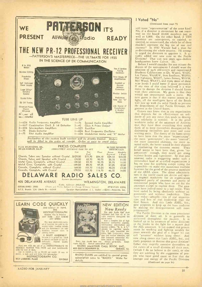
WE PWÚ PRESENT AllWa''
so
N IT'S
adio READY
THE NEW PR -12 PROFESSIONAL RECEIVER -PATTERSON'S MASTERPIECE -THE ULTIMATE FOR 1935
IN THE SCIENCE OF DX COMMUNICATION 8 tc 550
Meters
Shielded 100' ;
Preselector Stages
Self Contained Power Supply
Large 10 /." Dynamic Speaker
Crystal Filter
SS CW Tuning
Chromium Plated Chassis
18 -gauge
TUBE LINE UP I -6D6 Radio Frequency Amplifier I -6A7 Combination Oscil. & Ist Detector 2 -6D6 Intermediate Amplifiers
1 -75 Diode Detector 1 -75 First Audio Amplifier
1-76 2-42 I-5Z3 I-6D6 I-6D6
New 6 Section Tuning
Condenser
Three Stages AF Amplification
Douhlett or Marconi Antenna
Connection
Monitor Switch
Modulation '.leter and "R"
Meter
Liti Wound IF Transformers 6 Months' Guarantee
Second Audio Amplifier Class A Prime Output Rectifier Beat Frequency Oscillator Modulation Meter and "R" Meter
Production of this custom built receiver will be strictly limited. Orders will be filled in the order of receipt. Order at once to avoid delay.
F.O.B. WILMINGTON, DEL. OR LOS ANGELES. CALIF. ABSOLUTELY NOTHING ELSE TO BUY
List Net C »,,
Chassis, Tubes and Speaker without Crystal 5129.50 $77.70 Chassis, Tubes and Speaker with Crystal _. . 139.50 83.70 Metal Case, Complete, without Crystal 139.50 83.70 Metal Case, Complete, with Crystal 149.50 89.70 Console, Complete, without Crystal 169.50 101.70 Console, Complete, with Crystal 179.50 107.70
PRICES COMPLETE NO TIME PAYMENTS OUTSIDE U.S.A.
TIM.' Doug n Monthly Payment 5 Pmts
$84.18 90.75 90.75 97.25
110.20 116.70
$34.18 $10.00 35.75 11.00 35.75 11.00 37.25 12.00 45.20 13.00 46.70 14.00
DELAWARE RADIO SALES CO. Eastern Distributors
405 DELAWARE AVENUE WILMINGTON, DELAWARE Cable Address: DELRAD
ESTABLISHED 1920 I I'nceo and Terms Subject to Change Without None,) ATTENTION W3DQ N.Y.C. Branch: 136 Liberty St. -W2KR Canadian Representative: J. L. Walker- VE3J1-- Rockciife, Ont.
LEARN CODE QUICKLY AND EASILY AT HUMu.
THE INSTRUCTOGRAPH
Enables You to Practice ANY TIME ANY WHERE
ANY SPEED
The most practicable meth- od of learning the rude on the market today. Leading schools and the Government use tape machines because there is nothing better.
A SMART INVESTMENT because it is priced low (cash or terms) and built to last in- definitely. Highest quality throughout.
Start now with the aid of an INSTRUCTOGR.4PIt TO QUICKLY MASTER THE CODE and send intelligently with the best of them.
Can be rented as low as $2 (III pia moth (3 mos. or more). A post card will bring NI iuf,.rru. r ion.
INSTRUCTOGRAPH CO. 915 LAKESIDE PLACE CHICAGO
NEW EDITION Now Ready
The only Radio Call Book published that lists all of the radio amateurs throughout the entire world.
Also a complete list of high frequency commercial stations. International abbreviations and amateur prefixes, "Q, R, & T," systems for reporting signala, New US radio inspection dis- tricts, high frequency prell. / time and weather schedules, and high frequency commercial sta- tions listed by frequencies.
Every ham should have one. Always up -to -date. Single copies $1.25. Annual subscription $4.00.
RADIO AMATEUR CALL BOOK, INC., 600 SOUTH DEARBORN ST. CHICAGO, ILL
RADIO CLUBS are entitled to special group subscription rates to "RADIO." Write for details.
I Voted "Noll (Continued from page 7)
still more "representation" of the same kind! No, if a director is competent he can repre- sent on the board 10,000 members just as well as 1,000. On the other hand, if TEN directors are incompetent, or cajoled, or coerced, or mesmerized, the whole lot of them couldn't represent the big toe of one real amateur ! In 1932 Warner had a plan for re- divisioning the whole country. He strong- ly urged the directors to approve it. It ac- tually added one new state to the Pacific Division ! That was two years ago- before headquarters knew Culver. Hi.
Before I would consider for one minute the desires of the secessionists I should want the opinions of such old- timers and experienced Southern Californians as Dr. Waters, W6EC, Lee Potter, W6AKW, Bert Sandham, W6VO, Hal Nahmens, W6HT, James Brown, W6VH, Mel Wood, W6AVJ, and many more of these wise heads I could name if space permitted. If any men of this class believed it a wise move to disrupt the division I should listen with close attention. My guess is that they would not countenance such a move. My next guess is that if this matter comes to a fight, all the intelligent hams of the South will line up with the solid North to prevent the despoilment of our Pacific Division, the greatest in the United States.
Grown men know that in any organization that depends for its effectiveness on soli- darity of aim any move that tends to destroy that solidarity is suicidal. It is the great weakness today of the amateurs of America that they have done everything they could think of to keep themselves disorganized by disjointing themselves into more and more warring units. The theory of the hams seems to have been that the more "organization ", the more "government ", the more "control ", the more contested elections, the more in- ternal strife, the better would be their chances of combatting the common enemy. Their belief seems to have been that, given "or- ganization" enough, they could get along without brains and experience. So that now amateur radio is staggering under such a tremendous load of so- called organization it has no time for anything except trying the impossible -to make this monstrous machine function for the good of the amateur members of the ARRL alone. The ablest administra- tors in the world could not devise and oper- ate organic machinery for an organization composed partly of amateurs and partly of commercial people who have no use for the amateurs except to exploit them. The ama- teurs have indeed come to a sad estate. They have ended by being absolutely without or- ganization and without leadership. They have today -actually -less of real organiza- tion and less of real leadership than the Girl Scouts. And this Little ARRL, Inc., now proposes to keep up the ham tradition by making the disorganization still more pronounced!
The Pacific Division is the most prominent division of them all. It is generally so acclaimed throughout the country. It is looked up to by amateurs of other divisions as the leader in the fight for a square deal for ALL amateurs. It has earned this promi- nence by working and fighting steadily for years towards the goal of a league we can call "amateur" without lying about. And now along comes this Little ARRL, Inc., and cooly proposes to destroy this great division! Either they stupidly conceive themselves as the rulers of a small division all their own, (which I do no believe is the case), or else they are working by the suggestion of peo- ple who have good cause to fear that the courage and energy of the Pacific Division
(Continued on page 34)
RADIO FOR JANUARY 33
www.americanradiohistory.com
RADIO REPAIR MEN -AMATEURS
SC.44 Jt Roebuck and Co., The World's Largest Mail Order Company (in the Radio and Parts business for almost 20 years) an- nounce for restricted distribution a new Radio Parts and Amateur Equipment Catalog.
24 -HOUR SERVICE Everything carried in stock -the broadest guarantee ever written- Complete satisfaction or your mon- ey refunded.
Write-today for catalog No. 63 R 61. We will put your name on our mail- ing list and send you this big, new catalog as soon as it is off the press.
SEARS, ROEBUCK and CO. CHICAGO, ILL.
LENZ MICROPHONE CABLES are constructed for perfect transmission of voice and sound. Eliminate man made interference and "HUMS."
Perfect for Short
Wave Shielded Rubber
Covered
A New Item That Is Popular CRYSTAL
MICROPHONE CABLES
For Sale by Leading Jobbers and Dealers Everywhere
West Cant Representative: FRANK A. EMMET
741 S. Burnside Ave., Los Angeles, Calif.
LENZ ELECTRIC MFG. CO. 1753 N. Western Avenue, Chicago
Please send me your new Catalog No. 21
Name
Address
City State
=QUALITY at a Price You Can Afford to Payl
FRANKLIN Transformers
Very conservative rat. Inga on Transformere and Chokes for every Amateur Station.
"MOST SOCK PER DOLLAR"
Write for Catalogs
FRANKLIN TRANSFORMER MFG. CO. 607 -609 22 Ave. N.E., Minneapolis, Minn.
will upset their private racket. The game looks like the old one: always split the opposition if you can and get them involved in an internal fight of their own. That is good political tactics and it has been em- ployed time and again in the ARRL. If the instigators of this especial occasion think the fight that will result from any attempt to disrupt and despoil the great Pacific Division will leave them unmaimed they are badly mistaken.
Clair Foster. W6HM.
COL. FOSTER'S IDEA OF A RETROACTION
Some Excerpts From a
Letter To W6GTE Dec. 13/34
W6GTE: KS for your very straightforward let- ter of December 11 regarding my yarn in December "RADIO ". 1 know it
takes considerable courage for a youngster to get up and paste a man of my years of experience in a hardboiled world, but I'm such a great admirer of courage -and I see so damn little of it among hams -that 1
positively LOVE the man who displays some of it, even when 1 myself am the object of his wrath.
Which being said I am now at liberty to tell you that aside from its frankness and its clarity of expression there is no other quality in your letter that commends it to me. Its animus is obvious -just from'your first para- graph in which you refer to my quotation of Schnell's remarks as the alleged state- ment of Fred Schnell's". You had read in the December "RADIO" article that I had taken the Schnell statement from the stenog- raphically recorded proceedings of the ARRL board meeting at which it was made. The term "alleged" might well be applied to "minutes" of board meetings such as are printed today but could hardly apply to state- ments appearing in proceedings recorded verbatim by court stenographer. So your choice of the word "alleged"- carrying the implication that you did not believe me- was gratuitous and indicative of your own state of mind towards me. Personal ani- mosity cannot be concealed, in either talk or writing, from an experienced observer.
Approaching a subject with personal am- mus is about the surest way of confusing one's logic. For example, I cannot follow your reasoning when you conclude your let- ter with, In the interest of fair play, Colonel, 1 believe that some sort of retraction is in order ". I don't question the sincerity of that belief ; to me it rings true. But 1 don't see how you conclude the retraction should come from me; or in fact that there is anything for me to retract. Schnell's remarks quoted from the record are clear and unqualified. It there is any retracting to be done it would seem to be on the part of Schnell himself.
This seems to be what caused you to con- clude that a retraction was due from me: You say that on October 30 you asked Schnell whether he had made the statement in 1923 that less than 20 per cent of the ARRL mem- bers were licensed amateurs and that, "He flatly denied making such a statement ". I am quoting you accurately, including the undet- scoring. Then, you say, Lansingh told him he was so recorded in the stenographic record of the board meeting of December 8, 1923. Whereupon, you say, "Mr. Schnell then stated that if he did say such a thing he had no recollection of it and in all probability re- ferred to the percentage of ARRL members who were actively engaged in message han- dling". _ _
(Continued on page 35)
AEROVOX for DEPENDABILITY IF you want that transmitter to stand up
and deliver the goods year in and year
out, with least cost to you, see that it's
equipped with ...
AEROVOX Oil - Filled Transmitting Con- densers ... quality inside and out ...latest engineering . remarkable performance
longest life and irresistible prices (for example: 2 mfd. 2000 v. $6.50 list!)
AEROVOX Grid Leak Resistors . . . also for voltage dividers . . adjustable contact slider . . . wire -wound, vitreous -enameled
. heaviest duty work. AEROVOX Mica Condensers ... precision units ... bakelite molded ... lowest dielec- tric losses . . . small in size and price but gigantic in usefulness.
And remember that Aerovox offers all other types of condensers and resistors for depend- able, economical, trouble -free service.
New Catalog 135 Edition ;use off the press des[ vibes complete Aero-
vox line. Also free copy of our monthly Research Worker.
CORPORATION 84 Washington St. Brooklyn, N. Y.
BIRNBACH- 10 BIRNeacHN046s
Superior - . (4 INSULATORS
BIBSBACII'S lnie of insulators and antenna
equipment is the largest available. "Navy -
Type' Insulators with center hole for an-
choring transmission line, and the "wing - Nut" Standoffs are popular new numbers.
Strong, highly -glued ceramic. Well- rounded
corners and edges. Nickel -plated brass hard-
ware. Write Dept. PR -1 foe Data.
BIRNBACH RADIO CO., Inc. 145 NuDSON 5TRErr 05W YORK CITY
LITTELFUSES Instrument Littlefuses. for meters, 1, 200 amp. up.
Hi.Volt Littlefuses foi transmitters, etc. 1000, 5000 and 10,000 volt ranges, I /16 amp. up. Neon Voltage Fuses & Indicators (Tattelites) 100, 250, 500, 1,000 & 2.000 volt ratings. Aircraft Fuses, Auto Fuses, Fuse Mountings, etc.
Get new Catalog No. 6
LITTLEFUSE LABS., 4503 Ravenswood Ave., Chicago, Ill.
34 RADIO FOR JANUARY
www.americanradiohistory.com
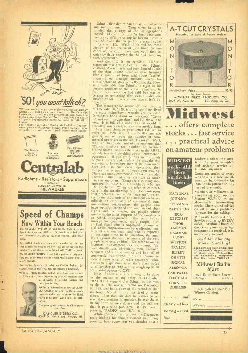
íÿ .0\d"-
! youruonflb /leñ "Where were you on the night of Ocember 13th T" Silent . .. silent as a door knob . . . Here's a tip. Inspector ... call a good serviceman and have him bring along some Centralabs ... chances are that's all your Superlodyne needs to make it tell all it knows. For a mere handful of Centralab Radiohm Replace- ment parts will service almost every known make of radio . . . and make it perk better than before.
The Sturdy Fired
RESISTOR The new patented
RADIOHM
The Efficient MOTOR RADIO
SUPPRESSOR
Radiohms - Resistors - Suppressors (Division of)
GLOBE UNION MFG. CO.
MILWAUKEE
Speed of Champs Now Within Your Reach
The CANDLER SYSTEM of learning the Code gives you
Speed, Accuracy and Ability. Be able to read fast press
and commercial stations as easily as you read your news-
paper.
Any skilled Amateur or commercial operator will tell you
that Candler Training is the best that can he had and that Candler Trained students copy behind with "mill" or pencil.
The CANDLER SYSTEM is not just a routine of code prac-
tice, hut an entirely different method that produces positive results quickly.
Our leading Operators of today are Candler Trained. Get started right so that you, too, can become a Champion.
Write for FREE bulletin, full of interesting items as well
as listing of stations broadcasting practice programs from
all districts. A splendid practice that costs you nothing.
Ask for full information on how the CAND LER SYSTEM can give you the necessary
speed to enable you to secure the ticket you're going after. Write now-no obli- gation.
Get your speed where the Champions got theirs.
CANDLER SYSTEM CO. 6345 So. Kedzie Ave., Chicago, Ill.
-#
Schnell first denies flatly that he had made any such statement. Then when he is re- minded that a copy of the stenographer's record had come to light he forthwith corn - menees to alibi by saying he has no recollec- tion of it and that he probably meant some- thing else. Hi. Well, if he had no recol- lection of his statement just how, do you conceive, he could have met your first in- quiry by flatly denying that he had made any such statement?
And the alibi is not credible. Hebert's statement that first Bidwell and then Schnell challenged was that it had been figured 10,000 of the then 14,000 members were licensed. Not a word had been said about "active" amateurs or message -handling amateurs - either before or after Schnell's remarks. Now, is it believable that Schnell is right in his present recollection that eleven years ago he didn't mean what he had said but was re- ferring to something that wasn't under dis- cussion at all! To a grown man it isn't be- lievable.
The stenographic record of that meeting of December 8, 1923, is quite complete. Even the most insignificent remarks are recorded. It makes a book about an inch thick. "Come up and see me some time" and I'll show it to you. It is full of disclosures that would be intensely interesting to any present -day ham.
One more thing in your letter I'd like to refer to. You say, "I personally am not greatly worried over the number of com- mercial operators in the ARRL ranks ". Well, who is? In the demand of the amateurs that Warner disclose the number of licensed United States amateurs there are in the ARRL, nobody has said anything about "commercial operators ". If you are putting in the minds of your hearers and readers the thought that we wish to know how may of the ham mem- bers are also commercial operators, then the premise is entirely of your own making. There are many commercial ops who are also licensed hams; and they are just as much hams as any of us. There are also many men engaged in radio for a livelihood who are licensed hams. When we refer to commer- cials in the membership of this organization that proclaims itself to be "amateur ", we re- fer to the thousands of non -amateurs who are officials or employees of commercial com- munications corporations -the people who have wellnigh stripped the amateurs of their rights and frequencies, the people whose money is the chief support of the employees at ARRL headquarters. We refer to at- torneys for commercial radio people -such as Paul Segal who is employed by commer- cial radio corporations -the traditional ene- mies of the amateurs -and who is expected at the same time to be guarding the ama- teurs against the encroachments of the very people who employ him! We refer to manu- facturers, non -amateur dealers, agents, job- bers, distributors, advertising men, salesmen, crooners and all the rag -tag and bob -tail of commercial radio who join this "Non -com- mercial association of radio amateurs" with- out even a question as to their class, color or citizenship so long as they cough up $2.50 for a subscription to QST.
Now, if there is any retracting to be done in the matter of my story in December "RADIO" I suggest that Schnell is the man to do it. He was a director on December 8, 1923, and has a copy of the record of that meeting. No doubt he has read it many times. If at this late date he wishes to re- tract the statement in question he may do so in any form he may devise and we will see that it gets wide publicity. If QST won't print it, "RADIO" and "R /9" will.
While you were going over my December story looking for some statement to rub my nose in, how come that you decided that a
A -T CUT CRYSTALS
o N
T
o R
Introductory
Mounted in Special Power Holder
Price
M o N
T
:o R
$5.95
MONITOR PIEZO PRODUCTS CO. 2802 W. Ave. 32 Los Angeles, Calif.
Midwest ... offers complete stocks ... fast service . . . practical advice on amateur problems MIDWEST stocks AL
these worthwhile
lines:
NATIONAL
JOHNSON SYLVANIA
RAYTHEON
RCA - DEFOREST
THOR- DARSON
HAMMAR - LUND
WESTON TAYLOR
BLILEY
OHMITE
SIGNAL
AEROVOX
CARDWELL
ELECTRAD
CORNELL- DUBILIER
and
every other recognized line
Midwest offers the ama- teur the most complete and reliable service ob- tainable anywhere. Complete stocks of every worthwhile line are al- ways on hand -ready for instant shipment to any part of the world. Members of Midwest's en- gineering staff operate Station W9RTV to an- alyze amateur transmitting needs. Their sound advice on all amateur problems is yours for the asking. Midwest's famous 4 hour Service applies to EVERY order. Within 4 hours of the time your order for equipment is received, it is on its way to you!
Send for Tbis Big Winter Catalog!
Send now for your FREE copy of the world's biggest catalog of short wate transmitting and receiving equipment. Mail the coupon TODAY!
Midwest Radio Mart
520 South State Street Chicago Illinois
Please rush me your Big Winter Catalog.
Name
Address
RADIO FOR JANUARY 35
www.americanradiohistory.com
"WEN
You Can't Hear Noise Because It Isn't There
THE resistance element is baked on the flat outer rim of a rigid Bakelite
ring. Over this, the special -alloy float- ing contact gently glides in a straight path. Result: The smoothest, quietest, long- est -lived volume control ever devised. Absolute quiet is further guaranteed by individual testing of each control at the factory. The molded Bakelite case, with remov- able metal end -cover, projects back - panel only 1/2 inch, when mounted. New -type power -switch (approved by underwriters) attached by a single screw. Extra -long, easily -cut aluminum shaft. Made in all standard sizes.
Guaranteed QUIET
Write Dept. PR -1 for Descript- ive Circular and the Nero 1935 Resistor Catalog.
FRANK C. JONES
JONES Consulting Engineer
Special High Frequency and Ultra High
Frequency Equipment Designed and
Developed for Amateur, Military and
Commercial Communications.
2037 Durant Ave. Berkeley, Calif.
defense of Schnell was necessary rather than a defense of the ARRL officers? It was the ARRL officers that the story showed up; it did not in the least question Schnell's state- ments or conduct. What the story disclosed was a new all -time high in mendacity by the IKKL headquarters In [rive wrung [u au amateur, "All voting in ARRL affairs is now restricted to licensed amateurs ". This glar- ing affront to the truth seems not to have caused you any uneasiness.
Let's look at the probable reasons why you jumped to the defense of Schnell, who needed no defense at all, while you failed to defend Warner who needs a hell of a lot more than you or anyone else will ever he able to provide. You have started to take me apart, OM, and you ought to know by this time that I can be depended upon to finish anything the other feller starts.
You are the secretary of the group that calls itself, "Federation of Radio Clubs of the Southwest, ARRL, a California Cor- poration". Which sounds big, at any rate. A group that is widely known to be backers of K. B. Warner. Your group publicly sup- ported Warner in his failure to report the truth of the Madrid convention's new restric- tion on amateur stations. It approved this restriction that aimed to kill the greatest pub- lic service the amateurs of the Pacific Division provide -the trans -Pacific traffic. Your group was AGAINST the efforts of those amateurs who were working to prevent the ratification of that restriction.
It is your group that has been working up interest in getting the southern half of the Pacific Division to secede and form a sepa- rate division. It was Matney, W6EQM, the ranking officer of your association who pro- posed this disruption of our division at the Fresno convention in November. It is com- mon knowledge that your group has sided with the ARRL officers against all the ama- teurs of the United States who are endeavor- ing to clear the ARRL of certain abhorrent and destructive practices and that the officers welcome your assistance. It is well known that while the ARRL officers failed to send a headquarters man to the last Pacific Division convention -sponsored by the San Jose Club -they did send one, Warner's right -hand man, to a hamfest arranged by your group since then. The first instance of a head- quarters man being sent clear across the con- tinent to a mere hamfest. It is well known that this same man, Budlong, spent much of his time with the officers of your group on a more recent trip to this coast. Perhaps you will tell us that all of these significant cir- cumstances have nothing to do with your reason for ignoring the chief theme of my December story -this latest audacity of the ARRL headquarters.
I am glad you wrote me when and as you did. I was just writing my story for January "RADIO ". Your letter provides some addi- tional ideas. You will recall that when I
voted "NO" on the Matney proposal I was asked if I would be willing to give my rea- sons and that I replied I would do so in writ- ing. I prefer to do my talking in writing or print rather than orally. That's what consti- tutes my story for "RADIO " -if the publish- er sees fit to use it. I like to say my say with black and white; then if I pull a boner the gang can nail me to the mast. Incidentally it guards against misquotations, although being misquoted does not worry me. We are all misquoted at times. There are only two kinds of men who escape it -those who never open their mouths and those who never say anything worth listening to.
Thanks again for a letter that while it stirs my risibilities I am bound to concede, never- theless, is temperate and courteous.
73, CF W6HM
HEADQUARTERI E SERVE YOU BEST.
SEND FOR THIS CATALOG! IT LISTS EVERYTHING FOR SHORTWAVE
TRANSMITTING AND RECEIVING Aerials Chokes Coils and Forms Condensers Crystals and
Holders Dials and Knobs Insulators Jacks. Plugs Keys - Meters Monitors
Oscilloscopes Power Packs Presolectors Relays Receivers Resistors Sockets Transformers Transceivers Tubes - Tubing Wave Meter
NEW EQUIPMENT Transceivers:
NATIONAL HARVEY HAIG IS KNIGHT
NATIONAL "HRO" RCA -ACR 136 Hammarlund "Super Pro" SUPER SKYRIDER New Antenna Gear -New Tubes -and the complete Na-
tional line. ti.'rite for This Catalog
Allied Radio ALLIED RADIO CORPORATION 833 W. Jackson Blvd., Chicago, Dept. J.
Send me suf. FREE New 1935 Catalog with the complete Amateur Listing.
Name
Address
City
rr State
PROVEN DEPENDABLE PROFESSIONAL
BAND SPREAD DX5
BUILT -IN DYNAMIC BUILT-IN COIL SPEAKER HOLDER RACK
CONTINUOUS BAND HIGH SENSITIVITY
SPREAD AND SELECTIVITY AEROPLANE DIAL
SELF CONTAINED MANUAL ANTENNA AC SHORT -WAVE CONTROL POWER SUPPLY HIGH FIDELITY 5 DISTINCT WAVE 5 NEW TUBES USED BANDS VERY EASY TO
ALL WAVE CONSTRUCT
Complete kit, including Dynamic speaker, el power supply, coils from 14 to 200 mr J
ters, coil holder rack and complete in-
structions. Special Offer Black crackle finished metal cabinet $2.50 Kit of matched ARCTURUS tubes 3.10 Broadcast coil, 200 -550 Meters .95 1f you prefer it Custom Built, add 2.50
Send 6e in stamps for descriptive circular Order From This Ad Now While We Can Guarantee
These Low Prices!
WORLD TROTTEK RADIO LABS. 168 Washington St., Division Rl, New York, N. Y
S 1 Brings You the Next 4 Issues
of "RADIO " -- Subscribe Now
36 RADIO FOR JANUARY
1
www.americanradiohistory.com
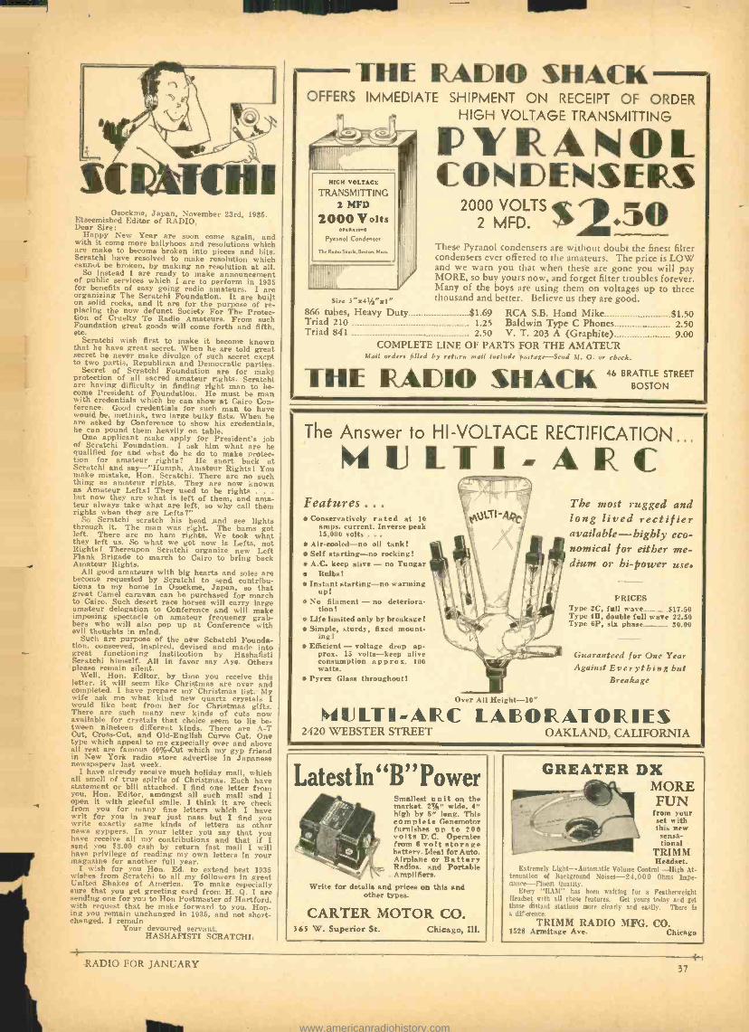
Osockme, Japan, November 23rd, 1935. Etseemished Editor of RADIO, Dear Sire:
Happy New Year are soon come again, and with it come more ballyhoos and resolutions which are make to become broken into pieces and bits. Scratchi have resolved to make resolution which cannot be broken, by making no resolution at all.
So instead I are ready to make announcement of public services which I are to perform in 1935 for benefits of easy going radio amateurs. I are organizing The Scratchi Foundation. It are built on solid rocks, and it are for the purpose of re- placing the now defunct Society For The Protec- tion of Cruelty To Radio Amateurs. From such Foundation great goods will come forth and fifth, etc.
Scratchi wish first to make it become known that he have great secret. When he are told great secret he never make divulge of such secret exept to two partis, Republican and Democratic parties.
Secret of Scratchi Foundation are for make protection of all sacred amateur rights. Scratchi are having difficulty in finding right man to be- come President of Foundation. He must be man with credentials which he can show at Cairo Con- ference. Good credentials for such man to have would be, methink, two large bulky fists. When he are asked by Conference to show his credentials, he can pound them heavily on table.
One applicant make apply for President's job of Scratchi Foundation. I ask him what are he qualified for and what do he do to make protec- tion for amateur rights? He snort back at Scratchi and say -"Humph, Amateur Rights! You make mistake. Hon. Scratchi. There are no such thing as amateur rights. They are now known as Amateur Lefts! They used to be rights . . .
but now they are what is left of them, and ama- teur always take what are left, so why call them rights when they are Lefts ?"
So Scratchi scratch his head and see lights through it. The man was right. The hams got left. There are no ham rights. We took what they left us. So what we got now is Lefts, not Rights! Thereupon Scratchi organize new Left Flank Brigade to march to Cairo to bring back Amateur Rights.
All good amateurs with big hearts and soles are become requested by Scratchi to send contribu- tions to my home in Osockme, Japan, so that great Camel caravan can be purchased for march to Cairo. Such desert race horses will carry large amateur delegation to Conference and will make imposing spectacle on amateur frequency grab- bers who will also pop up at Conference with evil thoughts in mind.
Such are purpose of the new Schatchi Founda- tion, conseeved, inspired, devised and made into great functioning institootion by Hashafisti Scratchi himself. All in favor say Aye. Others please remain silent.
Well, Hon. Editor, by time you receive this letter, it will seem like Christmas are over and completed. I have prepare my Christmas list. My wife ask me what kind new quartz crystals I would like best from her for Christmas gifts. There are such many new kinds of cuts now available for crystals that choice seem to lie be- tween nineteen different kinds. There are A -T Cut, Cross -Cut, and Old -English Curve Cut. One type which appeal to me expecially over and above all rest are famous 40% -Cut which my gyp friend in New York radio store advertise in Japanese newspapers last week.
I have already receive much holiday mail, which all smell of true spirits of Christmas. Each have statement or bill attached. I find one letter from you, Hon. Editor, amongst all such mail and I open it with gleeful smile. I think it are check from you for many fine letters which I have writ for you in year just pass but I find you write exactly same kinds of letters as other news gyppers. In your letter you say that you have receive all my contributions and that if I send you $3.00 cash by return fast mail I will have privilege of reading my own letters in your magazine for another full year.
I wish for you Hon. Ed. to extend best 1935 wishes from Scratchi to all my followers in great United Shakes of America. To make especially sure that you get greeting card from H. Q. I are sending one for you to Hon Postmaster of Hartford, with request that he make forward to you. Hop- ing you remain unchanged in 1935, and not short- changed, I remain
Your devoured servant, HASHAFISTI SCRATCHI.
THE RADIO %HACK OFFERS IMMEDIATE SHIPMENT ON RECEIPT OF ORDER
HIGH VOLTAGE TRANSMITTING
HIGH VOLTAGE
TRANSMITTING 2 MFD
2000 Volts rwc
Pyranol Condenser
The Radio Sauk. Boso, Mu..
Size 3 "z4% "zl" 866 tubes, Heavy Duty $1.69 RCA S.B. Hand Mike $1.50 Triad 210 1.25 Baldwin Type C Phones 2.50 Triad 841 2.50 V. T. 203 A (Graphite) 9.00
COMPLETE LINE OF PARTS FOR THE AMATEUR Mail order, filled by return snail include portage -Send M. O. or check.
FYIAOL CONDENSERS
2000 VOLTS $2 2 MFD. 5O
These Pyranol condensers are without doubt the finest filter condensers ever offered to the amateurs. The price is LOW and we warn you that when these are gone you will pay MORE, so buy yours now, and forget filter troubles forever. Many of the boys are using them on voltages up to three thousand and better. Believe us they are good.
THE RADIO %HACK 46 B R
BOSTON
The Answer to HI- VOLTAGE RECTIFICATION..
4 IJ L T I - A R C
0,31.Tl-AQCI
Features ... Conservatively rated at 10
amps. current. Inverse peak 15,000 volts .
Air -cooled -no oil tank! Self starting -no rocking! A.('. keep alive - no Tungar
Bulbs! Instant starting -no warming
up! No filament - no deteriora-
tion! Life limited only by breakage! Simple, sturdy, fixed mount-
ing! Efficient - voltage drop ap-
prox. 15 volts -keep alive consumption a p p ro x. 100 watts.
Pyrex Glass throughout!
1 1. er All Height
The most rugged and long lived rectifier available- highly eco- nomical for either me- dium or hi -power use.
PRICES Type 2C, full wave..__ ...... $17.50 Type 4B, double full wave 22.50 Type 6P, six phase. ... 30.00
Guaranteed for One Year Against Everything but
Breakage
1fIJLT1-ARC LABORATORIES 2420 WEBSTER STREET OAKLAND, CALIFORNIA
Latest In "B" Power Smallest unit on the market. VA" wide. 4" high by 5" long. Thla complete Genemotor furnishes up to 200 volts D.C. Operates from 6 volt storage battery. Ideal for Auto. Airplane or Battery Radios. and Portable Amplifiers.
Write for details and prices on this and other types.
CARTER MOTOR CO. 365 W. Superior St. Chicago, Ill.
GREATER DX MORE FUN
from your set with this new
sensa- tional
TRIMM Headset.
Extremely Light -Automatic Volume Control -high At- tenuation of Background Noises- 24,000 Ohms Impe- dance--Finest Quality.
Every "HAW has been waiting for a Featherweight Headset with all these features. Get yours today and get those distant stations more clearly and easily. There is a difference.
TRIMM RADIO MFG. CO. 1528 Armitage Ave. Chicago
RADIO FOR JANUARY 37
www.americanradiohistory.com
Radio Dealers and
Jobbers who desire to advertise in these
columns are invited to write for rates. BUYERS' GUIDE
A Monthly Listing of Reliable Radio Dealers and Jobbers who solicit the patronage of our readers. Buy from your nearest
Dealer or Distributor. He is
dependable and reliable.
CHICAGO, ILLINOIS
Chicago Radio Apparatus Company, Inc.
415 South Dearborn Street Harrison 2276
Dependable Radio Equipment
Established 1921
Bulletins on request -we specialize in short wave transmitting and receiving apparatus.
Catalog Ten cents.
CHICAGO, ILLINOIS
MiD -WEST RADIO MART 520 South State Street
CHICAGO
Write for Special Catalog -Free
CHICAGO, ILLINOIS
Newark Electric Company 226 W. Madison St.
Chicago All Kinds of Equipment for
Service Men - Amateurs - Experimenters \frite for free catalog
OAKLAND, CALIFORNIA
RADIO SUPPLY CO. 2085 BROADWAY. Hammarlund, Yaxley, Carter, National, John- son, ARC, Cardwell, Miller, Morrill, Flechteim,
Triplett, Haigis Transceivers W6GFY
ST. PAUL, MINNESOTA
LEW BONN COMPANY 2484 University Avenue
Rex L. Munger, W9LIP, Sales Engineer
Radio Wholesaler Complete Stock
BUFFALO, N. Y.
DYMAC RADIO 216 E. Genesee St. CL 2080
Complete Stock Amateur Parts
STANDARD DISCOUNTS
-W 8AW K-
LOS ANGELES, CALIFORNIA
RADIO SUPPLY CO. 912 SO. BROADWAY
The Amateurs' HEADQUARTERS of the WEST
All Nationally Advertised Parts for Receiving and Transmitting carried
in stock at all times.
9 Licensed Amateurs on Our Staff
ÑEW PR o DUCT! 212 and Five -Meter Doublet Antenna
The new American Radio Hardware Co. 21 and
-meter Doublet Antenna is a good solution to the antenna problems encountered in ultra -high fre- quency transmission and reception. It has always been the desire of the amateur to obtain the maxi-
alum efficiency from each piece of equipment used. Tests conducted within the last few months prove that successful high frequency transmission depends to a great extent on the type of antenna system employed. In most cases, 5 meter antennas were made by the cut and try method and it took hour' to "tailor" the antenna for the particular trans- mitter or receiver. With this new antenna with its special force type locking devices, it is a simple matter to obtain the proper length and this is im- portant - maintain these adjustments for long Periods of time.
The New G.E. Pyranol Transmitting Condensers
Inadvertently, the new G.E. Transmitting Con- denser cuts were used in this column of the De- cember issue of "RADIO" to describe a group of transmitting condensers manufactured by The Aerovox Corporation. The publishers hasten to correct this error. Here is a description of the new' G.E. product, illustrated in the cut below:
General Electric D -C, Transmitter Capacitors are filled and treated with Pyranol, a nonflammable, non explosive dielectric developed and patented by General Electric. Pyranol has extraordinary in- sulating and dielectric qualities, and its use makes Possible an unusually small and compact unit for all transmitter capacitor ratings. Compare the size with a capacitor of conventional design.
The lacquer- finished cases are hermetically sealed, assuring permanence of the characteristics of the capacitors, as contamination from air and moisture is impossible. Long life and ability to withstand temperatures as high as 75 deg. C. make these capacitors outstanding in their field. Porcelain bushings and mounting feet are included as stand- ard equipment, and the units can be mounted in any position. They are suitable for continuous operation at voltages up to 10 per cent above the rated values.
The New General Electric Pyranol Transmitting Condensers
CHICAGO, ILLINOIS
Chicago Radio Apparatus Company, Inc.
415 South Dearborn Street Harrison 2276
Dependable Radio Equipment
Established 1921
Bulletins on request -we specialize in short wave transmitting and receiving apparatus.
Catalog Ten cents.
BUTLER, MISSOURI
HENRY RADIO SHOP Complete stock of Collins, Patterson, Na tional, Hammarlund, Silver, CornellDubi lier, Thordarson, Sylvania, Taylor, Card- well, Triplett, Bliley, Trimm, Johnson, Turner, and others at lowest wholesale prices. Your used apparatus accepted in trade, too. Write for any information.
211 -215 N. MAIN
FRESNO, CALIFORNIA
PORTS MANUFACTURING CO.
3265 E. Belmont Ave. Radio W6AVV National FB7 -SW3 and Parts; Hammarlund,
Cardwell. Bliley Crystals; Johnson Insulators. Distributors RCA DeForest Transmitting Tubes
Established 1914 Send for Wholesale Catalog
SAN FRANCISCO, CALIFORNIA
t
EÑ8ACH ELECTR /C COMPANY
1452 Market Street. "The House of a Million Radio Parts"
Hammarlund and National sets and parts. Sylvania Amateur Transmitting Tubes
Collins Transmitters. Arcturus Receiving Tubes. Trimm Phones, all types.
Johnson Antenna Feeders, Insulators, Transposition Blocks.
SEATTLE. WASHINGTON
SEATTLE RADIO SUPPLY
.,,..ra,,,o.,.,i. i-ATTi.. A,,,.,,TO. LARGEST PARTS SUPPLY DEPOT
IN THE NORTHWEST
Four of Our Employees Are Licensed
W7BRS Amateurs W7CR
W7AVC W7WE
CORNELL DUBILIER, BLILEY, PATTERSON
SETS, COLLINS. WARD, LEONARD, UNITED TRANS.
SCHENECTADY, NEW YORK
Eastern Radio Supply Company 712 Broadway
Wholesale Distributors of Tubes, Pacts, and Test Equipment for
Service Mcn Amateurs Experimenters Write for Zuetations
s8
4- RADIO FOR JANUARY
www.americanradiohistory.com
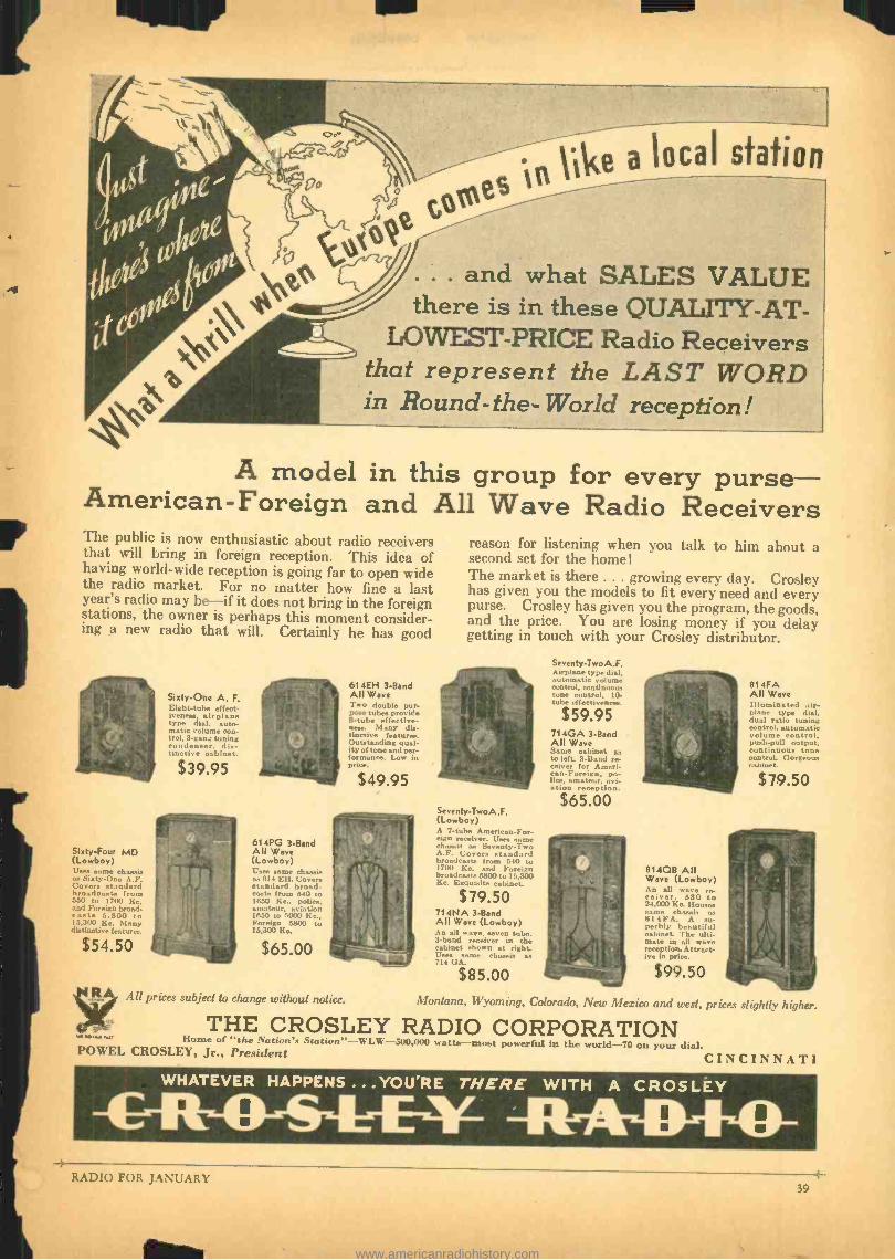
i
.. and what SALES VALUE there is in these QUALITY -AT-
LOWEST -PRICE Radio Receivers that represent the LAST WORD in Round-the-World reception!
A model in this group for every purse- American-Foreign and All Wave Radio Receivers The public is now enthusiastic about radio receivers that will bring in foreign reception. This idea of having world -wide reception is going far to open wide the radio market. For no matter how fine a last year's radio may be-if it does not bring in the foreign stations, the owner is perhaps this moment consider- ing a new radio that will. Certainly he has good
Sixty -One A. F. Eightube effect- iveness. airplane type dial, auto- matic volume con- trol, 3 -gang tuning condenser, dis- tinctive cabinet.
$39.95
Sixty -Four MD (Lowboy) Uses same chassie as Sixty-Ono A.F. Covers standard broadcasts from 550 to 1700 Kr. and Foreign broad- casts 5.800 to 15,300 Kc. Many distinctive features.
614PG 3 -Band All Wave (Lowboy) Usas same chassis as 614 Eli. Covers standard broad- casts from 540 to 1650 Ke.. police, amateur, aviation 1850 to 5000 Kc., Foreign 5800 to 15,300 Kc.
$65.00
614EH 3 -Band All Wave Two double pur- pose tubes provide 8 -tube effective- ness. Many dis- tinctive features. Outstanding qual- ity of tone and per- formance. Low in price.
$49.95
All prices subject to change without notice.
reason for listening when you talk to him about a second set for the home !
The market is there ... growing every day. Crosley has given you the models to fit every need and every purse. Crosley has given you the program, the goods, and the price. You are losing money if you delay getting in touch with your Crosley distributor.
Seventy -TwoA.F. (Lowboy) A 7 -tube American -For- eign receiver. Uses name chassis as Seventy -Two A.F. Covers standard hroadca.sts from 5.10 to 1700 Kv. and Foreign broadcasts 5M00 to 15,300 Kr. Exquisite cabinet.
$79.50 714NA 3 -Band All Ware (Lowboy) An all wave, seven tube, 3 -band receiver in the cabinet shown at right. Uses sane chassis as 714 (lA.r
$85.00
Seventy -TwoA.F. Airplane type dial. automatic volume control, contiguous tone control, 10. tube effectiveness.
$ 59.95 714GA 3 -Band All Wave Same cabinet as to left. 3 -Band re- ceiver for Ameri-
lcan-Foreign, po-
ice, amateur. avi- ation reception.
$65.00
81408 All Wave (Lowboy) An all wave re- ceiver, 530 to 24,000 Kr. (louses same chassis as 814FA. A su- perbly beautiful cabinet. The ulti- mate in all wave reception. Attract. ive in price.
$99.50
B14FA All Wave Illuminated air- plane type dial. dual ratio tuning control, automatic volume control, push -pull output, continuous tone control. Gorgeous cabinet.
$79.50
Montana, Wyoming, Colorado, New Mexico and west, prices slightly higher.
THE CROSLEY RADIO CORPORATION Home of "the Nation's Station " --\i I -500,000 watts -moat powerful in the world -70 on your dial. POWEL CROSLEY, Jr., President CINCINNATI
WHATEVER HAPPENS ...YOU'RE THERE WITH A CROS LEY
-Ri-A-41)443- RADIO FOR JANUARY
39 -
www.americanradiohistory.com
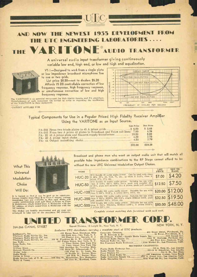
AND NOW THE NEWEST 1935 DEVEL.OPNENT PROW
THE UTC ENGINEERING I AIOIR ATORIES ... .
THE VA R 1 T O N lE AUJ IDiO TRANSFORMER A universal audio input transformer giving continuously variable low end, high end, or low and high end equalization.
VT -I- Designed to work from a single plate or low impedance broadcast microphone line
to one or two grids. List price $8.50 -net to dealers $5.20
Affords 15 DB controllable correction of low
frequency response, high frequency response,
or simultaneous correction of low and high
frequency response.
The VARITONE is an essential component for high fidelity theatre and PA amplifiers. Manufacturers of such equipment are invited to write us regarding the application of the VARITONE to their equipment.
.PATENT APPLIED FOR
2
e
6 tr)
W _6
inn NORMAL CURVE ._,111
10 PA1 ,'HIGH-END
`iS1 EQUALIZATION .41.11-1n
1111111 11111Ii,, LOW-HIGH EQUALIZATION 011151111
IIIIIIn I111111 1121111 11111 . \.11111 /%101 1111l.......C::e0!..._
LOW-END EQUALIZATION Mi.
50 100 500 1000 3000 loo,' FREQUENCY IN CYCLES PER SECOND
Typical Components for Use in a Popular Priced High Fidelity Receiver Amplifier
Using the VARITONE as an Input Source. List Price Net Price
PA -233 From two triode plates to 45 A prime grids $ 6.00 $ 3.60
PA -245 From two A prime 45 plates to Broadcast and Voice coil lines 7.00 4.20
PA- 22 45 A prime plate and filament supply transformer 10.00 6.00
PA- 40 A prime input choke 4.50 2.70
PA- 44 Output smoothing choke 4.50 2.70
$32.00 $19.20
What This
Universal
Modulation
Choke
Will Do:
-+
It is tapped so that it can be used as an autotrans- former coupler from ('lass B to Class C stages; various impedance taps are available so that each choke will readily accommodate push pull Class A -Prime or ('lass B Modulators, single ended ('lass A Modulator with the DC adding. or single ended Class A Modulator with the D(' bucking. The chokes are huskily constructed and air gaps are arranged to take care of the maximum D(' currents.
Broadcast and phone men who want an output audio unit that will match all
possible tube impedance combinations to the RF Stage cannot afford to be
without the new UTC Universal Modulation Output Chokes.
TYPE LIST
PRICE NET TO
HAMS
HUC-20
H U C 5O
HUC -) OO
Will handle 20 watts audio power. Can be used with class B 46's, 59's, 53. 6A6, 79, etc., or class A 2A3's, class A
,rime 42's. 45's, etc. X7.00s AAt.0
Will handle 50 watts audio power. Suitable for use with lass B 210'3, 801'x, R30's, 841'x, push Pull parallel 46's
or 59's, push pull parallel 45'3 A Prime, Push pull parallel 'A3's.
$ 1 2.50 $ L $7.50 Will handle 100 watts audio power. Suitable for use with -lass B 800's, 211E's, A prime 284's, 845'8, etc.
$20.00 `PL
1 1 2.00
HUC -200 Will handle 200 watts audio power. Suitable for use with 'lass B 203's, 830B's, HK- 354's, single EIMAC 150T, push pull parallel 845's, prime. etc.
$32.50 X32 9.50 C 00 HUC-500 Will
handle 500 watts audio power. Suitable for use with class B 204'8, HK354's, EIMAC 150T's, A prime 212D's, $80.00 8 v // QQ $48 00
Complete circuit matching dots furnished with each unit.
UNITED TRANSFORINFR CORP. 264 -266 CANAL STREET Export Division 15 Leight St., New York, N. Y. NEW YORK, N. Y.
Exclusive UTC distributors carrying a complete stock of UTC products.
Goldhamer's, Inc. Wholesale Radio Service Co.. Inc. Wholesale Radio Sery ire ('r . I
Radio Service. 1n.. Sun Radio Gross Radio, Inc. Leeds William Gram Mohawk Electric I
Amite Radio Shack Nutter & Cross Radio Service Lab. of N. H. Retry & Young...._..,_
_..._..._..___..610 Huron Road, Cleveland, Ohio ...100 Sixth Ave., New York, N. Y.
219 Central Ave., Newark, N. J. 130 W. Peachtree St. N. W., Atlanta, Ga.
227 Fulton Street, New York, N. Y. 51 Vesey Street, New York City
_.45 Vesey Street, New York City 1444 Sheridan St., Lansing, Mich. 1335 State St., Schenectady, N. Y.
..1100 Pine St., St. Louis, Mo. 46 Brattle St., Boston, Mass.
990 Milk St., Boston, Mass. PIO. I:lin st., Manchester, New Hampshire
203 Ann St., Hartford, Conn.
Cameradio Company......_._._....... ..__.........._..._.._......603 Grant Street, Pittsburgh, Pa. W. H. Edwards & Co... _ .._.. __.._.........._.__- _.- .._...32 Sway, Providence, R. I.
SEATTLI.E, WASH. -Seattle Radio Supply Inc......_...._._.._ ....2319 Second Ave. Portland Radio Supply Co. _1300 W. Burnside, Portland, Ore. Spokane Radio Co., Inc 611 First Ave., Spokane, Wash. San Francisco Radio Exchange 1284 Market St.. San Francisco, Calif.
SOUTHERN CALIFORNIA Pacific Radio Exchange Inc....__........_._. ...........729 S. Main St., Los Angeles Radio Supply Co 912 -14 S. Broadway, Loa Angeles Coast Electric Co. _. ....._.. ...- ...__.._.. _...._._._...._.__.__..._._.744 G. St., San Diego Prest & Dean Radio Co...._._ - ......_.....400 American Avenue, Long Beach Radio Television Supply Co. 1701 S. Grand Ave., Los Angeles, Calif. Radio Specialties Co._.___ _1816 West 8th St., Los Angeles, Calif.
www.americanradiohistory.com
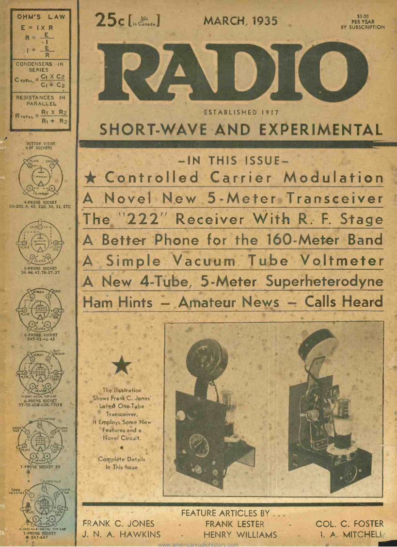
OHM'S LAW
E = IX R
R_ E
E R
CONDENSERS IN SERIES
C TOTAL - Ct X C2 Ct+ C2
RESISTANCES IN PARALLEL
Ri X R2 R TOTAL =
Ri + R2
BOTTOM VIEWS OF SOCKETS
PLATE GR
FILAMENT
4-PRONG SOCKET 50- 201 -A, 45, 210, 30, 31, ETC.
5 -PRONG SOCKET 56.46. 47.76.27 -37
6 -PRONG SOCKET 2A5-41-42-43
GRID -METAL TOP CAD
6 -PRONG SOCKET 57- 58- 6C6- 6D6 -77 -78
30c 25c [in Canede] MARCH, 1935 $3 00 PER YEAR
BY SUBSCRIPTION
ESTABLISHED 1917
SHORT -WAVE AND EXPERIMENTAL
-IN THIS ISSUE - * Controlled Carrier Modulation A Novel New 5-Meter Transceiver The "222" Receiver With R. F. Stage A Better Phone for the 160 -Meter Band
A Simple Vacuum Tube Voltmeter A New 4 -Tube, 5-Meter Superheterodyne Ham Hints - Amateur News - Calls Heard
The Illustration Shows Frank C. Jones'
Latest One -Tube Transceiver.
It Employs Some New Features and a
Novel Circuit.
7 -PRONG SOCKET 59 í
Complete Details in This Issue
4.GRID NT4 -METAL TOP CAP
7 -PRONG SOCKET 2A7 -6A7
FRANK C. JONES FEATURE ARTICLES BY ...
FRANK LESTER
J. N. A. HAWKINS - HENRY WILLIAMS COL. C. FOSTER
- I. A MITCHEL' MIN www.americanradiohistory.com
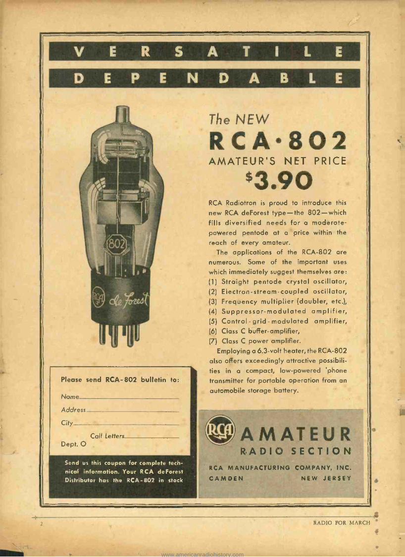
V E R S A T I L E
D E P E N D A B L E
Please send RCA -802 bulletin to:
Name
Address
City_
Call Letters__ Dept. O
Send us this coupon for complete tech- nical information. Your RCA deForest Distributor has the RCA -802 in stock
The NEW
RCA802 AMATEUR'S NET PRICE
$3.90 RCA Radiotron is proud to introduce this
new RCA deForest type -the 802 -which fills diversified needs for a moderate - powered pentode at a price within the
reach of every amateur.
The applications of the RCA -802 are
numerous. Some of the important uses
which immediately suggest themselves are:
(1) Straight pentode crystal oscillator, (2) Electron- stream -coupled oscillator, (3) Frequency multiplier (doubler, etc.),
(4) Suppressor -modulated amplifier, (5) Control - grid - modulated amplifier, (6) Class C buffer- amplifier, (7) Class C power amplifier.
Employing a 6.3 -volt heater, the RCA -802
also offers exceedingly attractive possibili-
ties in a compact, low- powered 'phone
transmitter for portable operation from an
automobile storage battery.
AMATEUR RADIO SECTION
RCA MANUFACTURING COMPANY, INC.
CAMDEN NEW JERSEY
L RADIO FOR MARCH
s
www.americanradiohistory.com
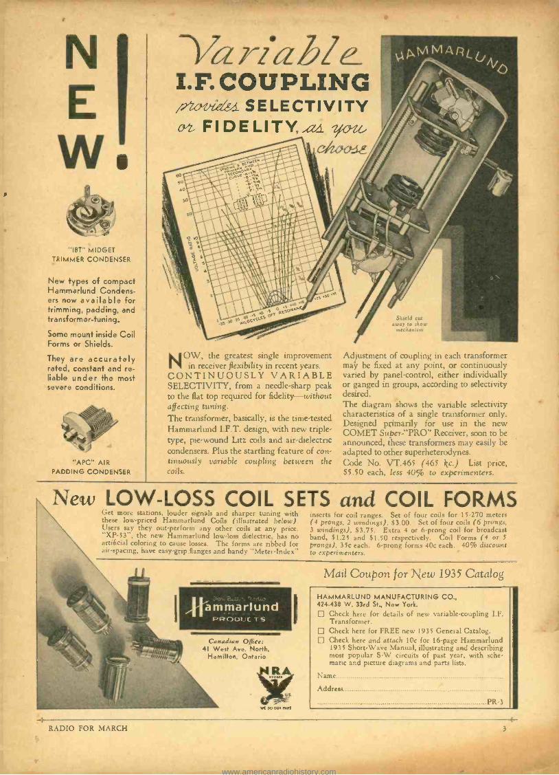
"IBT" MIDGET TRIMMER CONDENSER
New types of compact Hammarlund Condens- ers now available for trimming, padding, and transformer -tuning.
Some mount inside Coil Forms or Shields.
They are accurately rated, constant and re- liable under the most severe conditions.
"APC" AIR PADDING CONDENSER
Gr YI ah/ e_ I.F. COUPLING j7-1,0-ve SELECTIVITY vz FIDELITY aa w-e&
el2arl-
NOW, the greatest single improvement in receiver flexibility in recent years.
CONTINUOUSLY VARIABLE SELECTIVITY, from a needle -sharp peak to the flat top required for fidelity -without affecting tuning. The transformer, basically, is the time -tested Hammarlund I.F.T. design, with new triple - type, pie -wound Litz coils and air -dielectric condensers. Plus the startling feature of con- tinuously variable coupling between the coils.
Shield cut sway to show
mechanism
Adjustment of coupling in each transformer majy be fixed at any point, or continuously varied by panel -control, either individually or ganged in groups, according to selectivity desired. The diagram shows the variable selectivity characteristics of a single transformer only. Designed primarily for use in the new COMET Super -"PRO" Receiver, soon to be announced, these transformers may easily be adapted to other superheterodynes. Code No. VT.465 (465 kc.) List price. $5.50 each, less 40% to experimenters.
New LOW -LOSS COIL SETS and COIL FORMS Get more stations, louder signals and sharper tuning with these low- priced Hammarlund Coils (illustrated below). Users say they out- perform any other coils at any price. "XP -53 ", the new Hammarlund low -loss dielectric, has no artificial coloring to cause losses. The forms are ribbed for air -spacing, have easy -grip flanges and handy "Meter -Index-
Rammarlund _. _-... .
vcentii.c -rs
Canadian Office: 41 West Ave. North,
Hamilton, Ontario
T
i
WI DO OUR PART
inserts for coil ranges. Set of four coils for 15.270 meter- ( 4 prongs. 2 windings), $3.00. Set of four coils (6 prongs, 3 windings), $3.75. Extra 4 or 6 -prong coil for broadcast band, $1.25 and $1.50 respectively. Coil Forms (4 or 5
prongs), 35c each. 6 -prong forms 40c each. 40% discount to experimenters. -
Mail Coupon for New 1935 Catalog
IAMMARLUND MANUFACTURING CO., 424 -438 W. 33rd St., New York.
Check here for details of new variable -coupling I.F. Transformer. Check here for FREE new 1935 General Catalog. Check here and attach 10e for 16 -page Hammarlund 1935 Short-Wave Manual, illustrating and describing most popular S -W circuits of past year, with sche- matic and picture diagrams and parts lists.
Name
Address
PR -3
RADIO FOR MARCH
www.americanradiohistory.com
Ait.(gesee.w- Father of Radio, whose genius has enriched human knowledge and enhanced human enjoyment of life and whose inventions still form the basis of vacuum tubes and oscillating circuits as we know them today
APPROVES AND USES IN HIS OWN EQUIPMENT
AMPEREXgTUBES LEE DE FoRE8T
R, nae FccLROORÇ:oRI
E6 o'..,.,, LOS
A'O[Lt. CALIIORMI
January 11, 1935. Amperex
Lost 3 uthoHope
Hope ts,Inc, Angeles, Calif. eet
Gentlemen
Li!
have been u sln
type s s of Ar e r ex
211 tut es h
s rviatraSher lave
Therapy Emitt r for sometmeepsI wish
to state
hus far we have had
nothit
est results
therefrom,
ed
n hava
Ampere,:
for our work
to thoe °f other
manufacturers which
qvf trleda
are
CCleased With
e
results
tt& e
Ve feel
d,
t the danufa power radio
are fortunate to
available oscillator
tubes
Very sincerely
Lec de Fores LLE LE
FOREST LA5ORATORIËS
°urs,
64
A full line of carbon de tubes special -
ly suitable for the high
ano
frequency cir- cuits employed in
diathermy and phy- sio- therapy oscillat- ors.
Tube types are avail- able which will op- erate efficiently at frequency ranges up to 100 megacycles.
AMPEREX ELECTRONIC PRODUCTS, Inc. 79 WASHINGTON STREET Distributed by BROOKLYN, N. Y.
RADIO TELEVISION SUPPLY CO. LOS ANGELES E. C. WENGER CO. OAKLAND RADIO SPECIALTIES CO. - - - LOS ANGELES
B. J. De JARNATT FRESNO SAN FRANCISCO RADIO EXCHANGE ZACK RADIO SUPPLY CO.
SAN FRANCISCO SAN FRANCISCO HENDERSON BROS. SACRAMENTO
ELECTRIC SUPPLY CO. - - - OAKLAND COAST ELEC. CO. SAN DIEGO
RADIO FOR MARCH 4-
www.americanradiohistory.com
BRANCH OFFICES: New York City,
253 W. I 28th St. Tel. MOnument 2 -2812
Boston, J. H. Condon, 6 Marlboro St.
Chicago, C. W. Nelson,
`3618 North Bernard St. Los Angeles, Calif.
1455 Glenville Drive. Tel. CRestview 4017
ESTABLISHED 1917 Reg. U. S. Pat. Off.
}A NATIONAL MAGAZINE - PUBLISHED MONTHLY Publication Offices- Pacific Building, San Francisco, California
Clayton F. Bane, Editor H. W. Dickow, Business Manager. D. B. McGown, Technical Editor. Frank C. Jones, Ultra- Short -Wave- Engineering Editor.
Clair Foster, Amateur Activity Editor. George B. Hart, Contributing Editor. C. C. Anderson, Engineering Draftsman
25c per copy, $3.00 per year by subscription in
the U.S. $4.00 elsewhere.
Send subscriptions to the
San Francisco office. Entered as second class matter at the Post Office at San Francisco, Cali- fornia, under the Act of March 3rd, 1879.
Vol. 17 MARCH, 1935 No. 3
&wLthÌohiaL ÇniiwwzL Shot in the Patio
The whispering campaigners have a new rumor afoot. "Colonel Foster shot in the war," they say. And this latest attempt to discredit the writings of the Colonel is used as a means to prove him of unsound mind. So the editor of this magazine made a request of the Colonel for the facts of his war injury. The following letter came in reply:
ARELIABLE citizen of New York has forwarded the remarks made to him by an amateur who is a supporter of
the present regime at ARRL headquarters. "This fellow, Foster, during his military
service suffered some kind of an injury. As a result he goes through a peculiar cycle; first he is a great friend of someone but as time passes he goes into a period in which he quarrels violently with the erstwhile friend for no reason except things of his own imag- ination. You know he gave the ARRL a motor -generator set which is still being used at WIMK. The man is really mentally un- sound and is to be pitied. That is the reason Warner does sot feel like showing him up."
The source of the tale is readily recogniz- able. Pres. Maxim in his last annual report to the ARRL directors referred to me as that unbalanced but 'influential leader. I have been plastered with Hartford labels for years, until I now look like an old suitcase that has been on several Cook's Tours. One of the choicest of the collection is one pro- vided by Budlong, Warner's assistant. He wrote one of the fine oldtimers in the East, "Foster would like to see the Headquarters spit in the faces of the commercials ", and the oldtimer sent the letter to me. Budlong's in- tention was to spread the impression that while the Headquarters men were living up to their much -advertised "high standard of conduct ", Foster represents the depth of ill - breeding.
But, for all I know, there may be some- thing in this claim that I am mentally un- balanced. The crazy man is the poorest judge in the world of his own mental state. The crazier he is the surer he is of his own sanity. so I would best leave mine to the de- cision of others -which may be, for all I know, merely an insanely adroit way of mak- ing people think I am sane. At any rate, per- haps I would better relate the story of my war injury. It may give the judges some slant of my present mental condition.
During the war a detail of us men of the Corps of Engineers was assigned to help the British repair a bridge the Germans had dynamited. The Germans came back and drove us off with rifle -fire. In beating it back to the British lines I turned my ankle znd was utterly unable to walk. I dragged myself into a shell -hole. A sergeant threw
himself into the hole beside me and explained that I would have to get out of there -that the Germans would surely come this far and would finish me. I showed him my predica- ment, that I couldn't put my foot to the ground. He urged that I must get out some- how and that if I could get on his back he would carry me in. I put my arms around his neck and he legged it for the rear with me on his back. On the way in a bullet hit me in the posterior, but the sergeant made good time and we reached the British lines without further mishap.
Now, of course I don't know how much, if at all, a wound in that location may affect a man's mind. Some men carry the seat of their intelligence in the seat of their pants, but whether I myself am one of those men I have no means of knowing. But whether it affected my mind or not I know it affected profoundly my faith in the unselfishness of human nature. The sergeant some months later said the only reason why he had stopped to carry me in was that I was so big I would afford fine protection for him.
Anyway, I got a bullet in the patio and he got the Victoria Cross for it.
For years I have kept this story to myself. This is the first time I have ever told it, but it seems only fair to give the pitying Mr. Warner a break.
-Clair Foster, W6HM.
"RADIO" Backs the League ADISTINGUISHED servant of the
League, peering into the narrow neck of an empty whiskey flask used
as a substitute for the mystic ball of a crystal- gazer, informed the publisher of this magazine that the League would put "RADIO" out of business unless our cam- paign of criticism is brought to a halt. Like the man who predicts the weather reports for the newspapers, we don't always get the kind of weather the papers like to give us. And so it was with the League prophet, when he forecast our early doom. For we were sup- posed to have been out of business at 2:15 A. M., three Saturdays ago. By some strange turn of fate we are still in business today. The score -one to nothing.
Unlike those who are trying so hard to subdue the growth of this magazine, "RADIO" has no desire to see the League go out of business. Quite the contrary. It is our sin- cere purpose to help strengthen the League structure; our campaign has not been directed at the League, as a League -it is aimed fairly and squarely at those who have taken it upon themselves to administer the affairs of the League as they see fit, not in accord with the wishes of a vast number of amateurs who are trying so hard to make the League a better organization to belong to.
All the constructive suggestions offered by this magazine have been poo- poohed by the square- jawed, two -fisted fighters at Hartford. For fighters they are -fighting to hold their jobs!
Now we are told that Congress can do nothing to pr6tect the future of amateur radio. The suggestion to solicit Congressional aid came from this magazine; consequently, it CAN'T be worth a whoop. If the suggestion were good, the League would have appealed to Congress years ago, you have been told. It is a matter of record that the amateur has fewer privileges at this time than he ever had before. Why? Because we did NOT solicit the aid of Congress. Running true to form, the criticism comes from those who are being criticised for not doing what they are paid to do. You, as amateurs, pay for protec- tion; why not make it your business to get it?
The commercial interests go to Congress and get what they want. They hire fat -sal- aried lobbyists. The amateur stays away from Congress and gets what the commercials feel like giving him. We ask one simple ques- tion -why does not the League spokesman join with us in this campaign to solicit Con- gressional aid? The answer seems quite ob- vious -the suggestion did not come from him!
The radio amateurs of Northern California recently met in San Francisco for the purpose of forming an alliance of radio clubs. A dele- gate from one of the clubs suggested the alliance be politics -free. Asked to define poli- tics, he replied -"Trying to get more fre- quencies is non -political; asking that we fire Warner is political."
To this writer it seems the reverse is true. In order to get more frequencies the greatest political drive in all amateur radio history must be waged; that drive is well under way.
Up stood another amateur from Warner's pet thorn -in- the -side radio club, San Jose, California. Said he: "I have recently been in conference with a former member of Congress. He tells me that in his 16 years of public service no request, to his knowledge, has ever been made by Mr. Warner for Congressional aid.
Every sane amateur KNOWS we must ap- peal to Congress at one . . . not two years hence! The wheels of government turn slowly. We must first acquaint our Con- gressmen with the deplorable conditions pre- valent in amateur radio. Further delay can prove disastrous. Stereotyped letters should not be sent to Congressmen. Write a simple, homely, sincere message to your Congressman. Tell him what we have today, what we had years ago; tell him how we lost what once was all our own. Ask for his cooperation in getting a little more breathing space in which to operate. The amateur is not unreasonable.
(Continued on page 33)
RADIO FOR MARCH 5
-r; ..
www.americanradiohistory.com
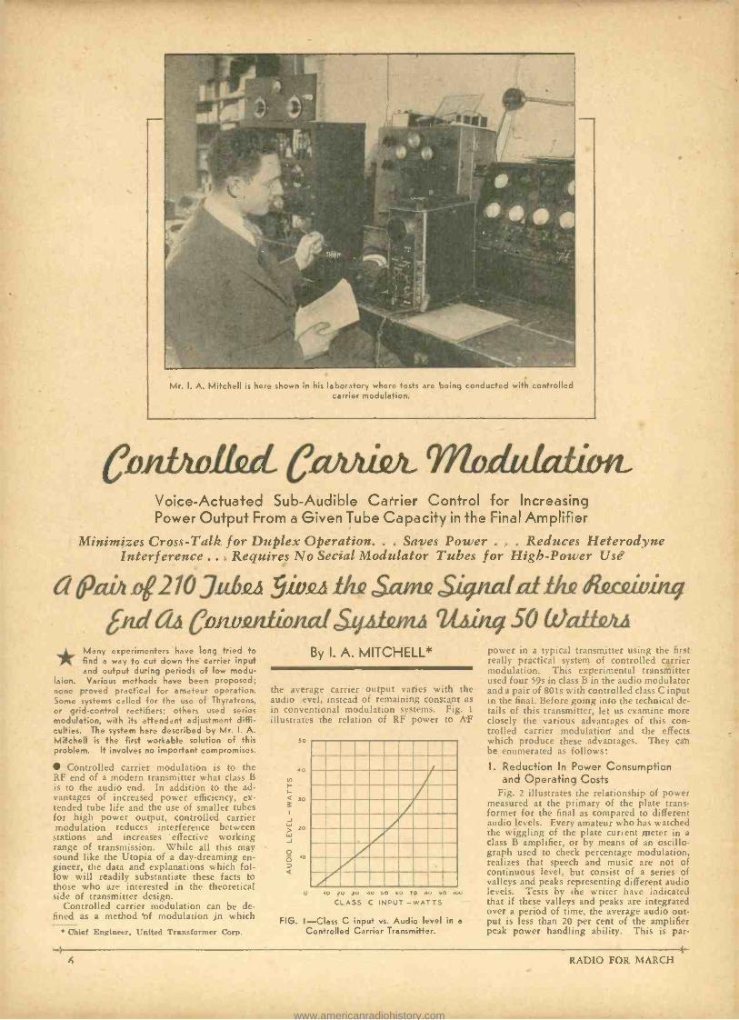
Mr. I. A. Mitchell k here shown in his laboratory where tests are being conducted with controlled carrier modulation.
ConDwitzd Ccuzitink Modu &lion_ Voice- Actuated Sub -Audible Carrier Control for Increasing Power Output From a Given Tube Capacity in the Final Amplifier
Minimizes Cross -Talk for Duplex Operation. . . Saves Power . . . Reduces Heterodyne Interference ... Requires No Secial Modulator Tubes for High-Power Use
a ó'abz 42 10 3.abizil ji. .tha SCUM Signalatidle &cavinq [iwl aa Convimlional Syzdunii 2r.ß 50 WatifvtA
Many experimenters have long tried to find a way to cut down the carrier input and output during periods of low modu-
laion. Various methods have been proposed; none proved practical for amateur operation. Some systems called for the use of Thyratrons, or grid -control rectifiers; others used series modulation, with its attendant adjustment diffi- culties. The system here described by Mr. I. A. Mitchell is the first workable solution of this problem. It involves no important compromises.
Controlled carrier modulation is to the RF end of a modern transmitter what class B is to the audio end. In addition to the ad- vantages of increased power efficiency, ex- tended tube life and the use of smaller tubes for high power output, controlled carrier modulation reduces interference between stations and increases effective working range of transmission. While all this may sound like the Utopia of a day -dreaming en- gineer, the data and explanations which fol- low will readily substantiate these facts to those who are interested in the theoretical side of transmitter design.
Controlled carrier modulation can be de- fined as a method of modulation in which
By I. A. MITCHELL*
the average carrier output varies with the audio level, instead of remaining constant as in conventional modulation systems. Fig. 1
illustrates the relation of RF power to AF
50
40
30
20
a
o o 20 30 40 50 60 70 60 90 400
CLASS C INPUT - WATTS
FIG. I -Class C input vs. Audio level in e
Chief Engineer, United Transformer Corp. Controlled Carrier Transmitter.
power in a typical tiais, nutter using the first really practical system of controlled carrier modulation. This experimental transmitter used four 59s in class B in the audio modulator and a pair of 801s with controlled class C input in the final. Before going into the technical de- tails of this transmitter, let us examine more closely the various advantages of this con- trolled carrier modulation and the effects which produce these advantages. They can be enumerated as follows:
I. Reduction In Power Consumption and Operating Costs
Fig. 2 illustrates the relationship of power measured at the primary of the plate trans- former for the final as compared to different audio levels. Every amateur who has watched the wiggling of the plate current meter in a class B amplifier, or by means of an oscillo- graph used to check percentage modulation, realizes that speech and music are not of continuous level, but consist of a series of valleys and peaks representing different audio levels. Tests by the writer have indicated that if these valleys and peaks are integrated over a period of time, the average audio out- put is less than 20 per cent of the amplifier peak power handling ability. This is par-
RADIO FOR MARCH
www.americanradiohistory.com
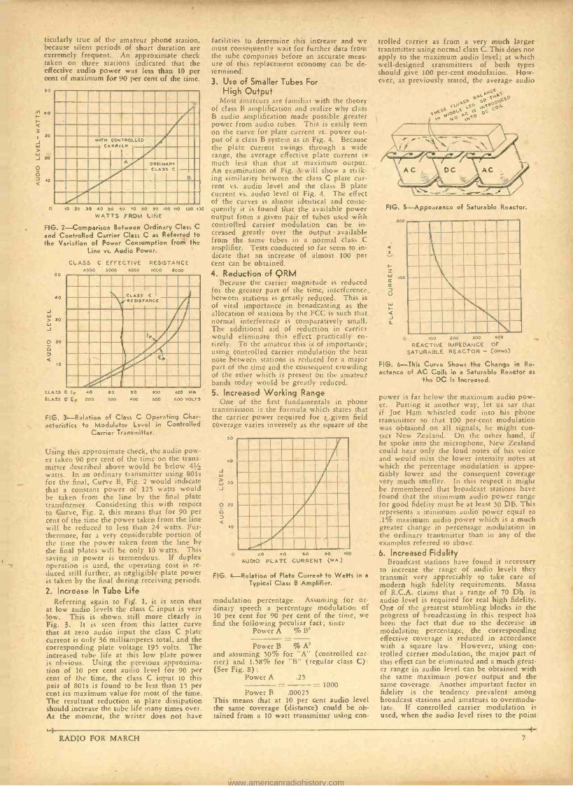
.a .atarw.
titularly true of the amateur phone station, because silent periods of short duration are extremely frequent. An approximate check taken on three stations indicated that the effective audio power was less than 10 per cent of maximum for 90 per cent of the time
50
40
á
I 30 J > W J 20
o O
w
WITH CONTROLLED CARRIER
ORO INAR7 CLASS C
B
O 10 20 30 40 50 60 70 60 90 100 NO 120 13C
WATTS FROM LINE
FIG. 2- Comparison Between Ordinary Class C and Controlled Carrier Class C as Referred to the Variation of Power Consumption from the
Line vs. Audio Power.
50
0 J W > 30
J
o 20
10
CLASS C EFFECTIVE RESISTANCE 000 5000 6000 7000 6000
CLASS C RESISTANCE
:LASS C Ip 40
CLASS C Ep zoo
60
300
60 400
400 500 420 MA
600 VOLTS
FIG. 3- Relation of Class C Operating Char- acteristics to Modulator Level in Controlled
Carrier Transmitter.
Using this approximate check, the audio pow- er taken 90 per cent of the time on the trans- mitter described above would be below 41/2
watts. In an ordinary transmitter using 801s for the final, Curve B, Fig. 2 would indicate
~ that a constant power of 125 watts would be taken from the line by the final plate transformer. Considering this with respect to Curve, Fig. 2, this means that for 90 per cent of the time the power taken from the line will be reduced to less than 24 watts. Fur- thermore, for a very considerable portion of the time the power taken from the line by the final plates will be only 10 watts. This saving in power is tremendous. If duplex operation is used, the operating cost is re- duced still further, as negligible plate power is taken by the final during receiving periods.
2. Increase In Tube Life Referring again to Fig. 1, it is seen that
at low audio levels the class C input is very low. This is shown still more clearly in Fig. 3. It is seen from this latter curve that at zero audio input the class C plate current is only 36 milliamperes total, and the corresponding plate voltage 195 volts. The increased tube life at this low plate power is obvious. Using the previous approxima- tion of 10 per cent audio level for 90 per cent of the time, the class C input to this pair of 8015 is found to be less than 15 per cent its maximum value for most of the time. The resultant reduction in plate dissipation should increase the tube life many times over. At the moment, the writer does not have
facilities to determine this increase and we must consequently wait for further data from the tube companies before an accurate meas- ure of this replacement economy can be de- termined. 3. Use of Smaller Tubes For
High Output Most amateurs are familiar with the theory
of class B amplification and realize why class B audio amplification made possible greater power from audio tubes. This is easily seen on the curve for plate current vs. power out- put of a class B system as in Fig. 4. Because the plate current swings through a wide range, the average effective plate current i9 much less than that at maximum output. An examination of Fig. -3 will show a strik- ing similarity between the class C plate cur- rent vs. audio level and the class B plate current vs. audio level of Fig. 4. The effect of the curves is almost identical and conse- quently it is found that the available power output from a given pair of tubes used with controlled carrier modulation can be in- creased greatly over the output available from the same tubes in a normal class C amplifier. Tests conducted so far seem to in- dicate that an increase of almost 100 per cent can be obtained. 4. Reduction of QRM
Because the carrier magnitude is reduced for the greater part of the time, interference. between stations is greatly reduced. This is of vital importance in broadcasting as the allocation of stations by the FCC is such that normal interference is comparatively small. The additional aid of reduction in carrier would eliminate this effect practically en- tirely. To the amateur this is of importance; using controlled carrier modulation the beat note between stations is reduced for a major part of the time and the consequent crowding of the ether which is present on the amateur hands today would he greatly reduced.
5. Increased Working Range One of the first fundamentals in phone
transmission is the formula which states that the carrier power required for á given field coverage varies inversely as the square of the
50
40
W
30 J
o 20
10
O 20 40 60 60 400
AUDIO PLATE CURRENT (MA)
FIG. 4- Relation of Plate Current to Watts in a
Typical Class B Amplifier.
modulation percentage. Assuming for or- dinary speech a percentage modulation of 10 per cent for 90 per cent of the time, we find the following peculiar fact; since
Power A % B2
Power B % A2 and assuming 50% for "A" (controlled car- rier) and 1.58% for "B" (regular class C): (See Fig. 8):
Power A .25 = 1000
Power B .00025 This means that at 10 per cent audio level the same coverage (distance) could be ob- tained from a 10 watt transmitter using con-
trolled carrier as from a very much larger transmitter using normal class C. This does not apply to the maximum audio level; at which well -designed transmitters of both types should give 100 per -cent modulation. How- ever, as previously stated, the average audio
ANCM ,t 0 f-O
Hi`EE
apJ `0oÉ'CS
O
o`
O ,Nt
FIG. 5- Appearance of Saturable Reactor.
200
MMOMMOMMIll IIMBEINEM Mil =MR ME Mill Milt IIIIIV mormamm En mama mulm mom.
o loo 200 300 400
REACTIVE IMPEDANCE OF
SATURABLE REACTOR - (onus)
FIG. 6-This Curve Shows the Change in Re- actance of AC Coils in a Saturable Reactor as
the DC Is Increased.
power is far below the maximum audio pow- er. Putting it another way, let us say that if Joe Ham whistled code into his phone transmitter so that 100 per -cent modulation was obtained on all signals, he might con- tact New Zealand. On the other hand, if he spoke into the microphone, New Zealand could hear only the loud notes of his voice and would miss the lower intensity notes at which the percentage modulation is appre- ciably lower and the consequent coverage very much smaller. In this respect it might be remembered that broadcast stations have found that the minimum audio power range for good fidelity must be at least 30 DB. This represents a minimum audio power equal to .1% maximum audio power which is a much greater change in percentage modulation in the ordinary transmitter than in any of the examples referred to above. 6. Increased Fidelity
Broadcast stations have found it necessary to increase the range of audio levels they transmit very appreciably to take care of modern high fidelity requirements. Massa of R.C.A. claims that a range of 70 Db. in audio level is required for real high fidelity. One of the greatest stumbling blocks in the progress of broadcasting in this respect has been the fact that due to the decrease in modulation percentage, the corresponding effective coverage is reduced in accordance with a square law. However, using con- trolled carrier modulation, the major part of this effect can be eliminated and a much great- er range in audio level can be obtained with the same maximum power output and the same coverage. Another important factor in fidelity is the tendency prevalent among broadcast stations and amateurs to overmodu- late. If controlled carrier modulation is used, when the audio level rises to the point
RADIO FOR MARCH 7
www.americanradiohistory.com
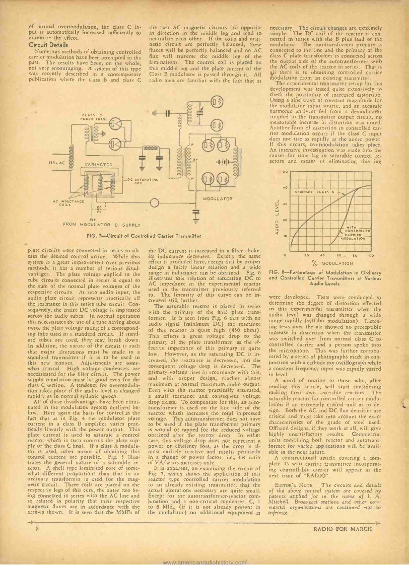
of normal overmodulation, the class C in- put is automatically increased sufficiently to minimize the effect. Circuit Details
Numerous methods of obtaining controlled carrier modulation have been attempted in the past. The results have been, on the whole, not very encouraging. A system of this type was recently described in a contemporary publication where the class B and class C
115v AC
CLA5S C
POWER TRANS
the two AC magnetic circuits are opposite in direction in the middle leg and tend to neutralize each other. If the coils and mag- netic circuit are perfectly balanced, these fluxes will be perfectly balanced and no AC flux will traverse the middle leg of the laminations. The control coil is placed on this middle leg and the plate current of the Class B modulator is passed through it. All radio men are familiar with the fact that as
IQ
VARIACTOR
:. :.7
I I DC SATURATING
COIL
AC INDUCTANCE COILS
B+ FROM MODULATOR B SUPPLY
FIG. 7- Circuit of Controlled Carrier Transmitter
plate circuits were connected in series to ob- tain the desired control action. While this system is a great improvement over previous methods, it has a number of serious disad- vantages. The plate voltage applied to the tube circuits connected in series is equal to the sum of the normal plate voltages of the respective circuits. At zero audio input, the audio plate circuit represents practically all the resistance in this series tube circuit. Con- sequently, the entire DC voltage is impressed across the audio tubes. In normal operation this necessitates the use of a tube having about twice the plate voltage rating of a correspond- ing tube used in a standard circuit. If stand- ard tubes are used, they may break down. In addition, the nature of the circuit is such that major alterations must be made to a standard transmitter if it is to be used in this new manner. Adjustments are some- what critical. High voltage condensers are necessitated for the filter circuit. The power supply regulation must be good even for the class C section. A tendency for overmodula- tion takes place if the audio level is changed rapidly as in normal syllabic speech.
All of these disadvantages have been elimi- nated in the modulation system outlined be- low. Here again the basis for control is the fact that as in Fig. 4 the modulator plate current in a class B amplifier varies prac- tically linearly with the power output. This plate current is used to saturate a control reactor which in turn controls the plate sup- ply of the class C final. If a class A modula- tor is used, other means of obtaining this control current are possible. Fig. 5 illus- trates the general nature of a saturable re- actor. A shell type laminated core of some- what different proportions than that in an ordinary transformer is used for the mag- netic circuit. Three coils are placed on the respective legs of this core, the outer two be- ing connected in series with the AC line and so related in polarity that their respective magnetic fluxes are in accordance with the arrows shown. It is seen that the MMFs of
MODULATOR
the DC current is increased in a filter choke, its inductance decreases. Exactly the same effect is produced here, except that by proper design a fairly linear relation and a wide range in inductance can be obtained. Fig. 6 illustrates this relation of saturating DC to AC impedance in the experimental reactor used in the transmitter previously referred to. The linearity of this curve can be in- creased still further.
The saturable reactor is placed in series with the primary of the final plate trans- former. It is seen from Fig. 6 that with no audio signal (minimum DC) the reactance of this reactor is quite high (450 ohms). This effects a great voltage drop to the primary of the plate transformer, as the ef- fective impedance of this primary is quite low. However, as the saturating DC is in- creased, the reactance is decreased, and the consequent voltage drop is decreased. The primary voltage rises in accordance with this, and with proper design, reaches almost maximum at normal maximum audio output. Even with the reactor practically saturated, a small reactance and consequent voltage drop exists. To compensate for this, an auto - transformer is used on the line side of the reactor which increases the total impressed voltage. This autotransformer does not have to he used if the plate transformer primary is wound or tapped for the reduced voltage obtained after the reactor drop. In either case, this voltage drop does not represent a power or efficiency loss, as the drop is al- most entirely reactive and results primarily in a change of power factor; i.e., the ratio of VA /watts increases only.
It is apparent, on examining the circuit of Fig. 7, which shows the application of this reactor type controlled carrier modulation to an already existing transmitter, that the actual alterations necessary are quite small. Except for the autotransformer- reactor com- bination and a non -critical condenser, C, 1
to 8 Mfd., (if it is not already present in the modulator) no additional equipment is
necessary. The circuit changes are extremely simple. The DC coil of the reactor is con- nected in series with the B plus lead of the modulator. The autotransformer primary is connected to the line and the primary of the class C plate transformer is connected across the output side of the autotransformer with the AC coils of the reactor in series. That is 41 there is to obtaining controlled carrier modulation from an existing transmiter.
The experimental transmitter set -up for this development was tested quite extensively to check the possibility of increased distortion. Using a sine wave of constant magnitude for the modulator input source, and an accurate harmonic analyzer fed from a demodulattir coupled to the transmitter output circuit, no measurable increase in distortion was noted. Another form of distortion in controlled car- rier modulation occurs if the class C input does not rise as rapidly as the audio power. If this occurs, overmodulation takes place. An intensive investigation was made into the causes for time lag in saturable control re- actors and means of eliminating this lag
SO
40
JO
20
10
ORDINARY CLASS C .-/ 1 .' TN _ Iimp CARRIER
LLED
MODULATION
O 20 40 60 SO
% MODULATION
FIG. 8- Parcentage of Modulation in Ordinary and Controlled Carrier Transmitters at Various
Audio Levels.
100
were developed. Tests were conducted to determine the degree of distortion effected in this experimental transmitter when the audio level was changed through a wide range rapidly (syllabic modulation). Listen- ing tests over the air showed no perceptible increase in distortion when the transmitter was switched over from normal class C to controlled carrier and a person spoke into the microphone. This was further corrobo- rated by a series of photographs made in con- junction with a cathode ray oscillograph while a constant frequency input was rapidly varied in level.
A word of caution to those who, after reading this article, will start considering making their own saturable reactors. The saturable reactor for controlled carrier modu- lation is an extremely critical unit as to de- sign. Both the AC and DC flux densities are critical and must take into account the exact characteristics of the grade of steel used. Offhand designs, if they work at all, will give highly unsatisfactory results. Commercial units combining both reactor and autotrans- former for varied applications will be avail- able in the near future.
A constructional article covering a com- plete 45 watt carrier transmitter incorporat- ing controllable carrier will appear in the next issue of "RADIO ".
EDITORS NOTE: The circuits and details of the above control system are covered by patents applied for in the name of I. A. Mitchell. Broadcast stations and other com- mercial organizations are cautioned not to infringe.
8 RADIO FOR MARCH
www.americanradiohistory.com
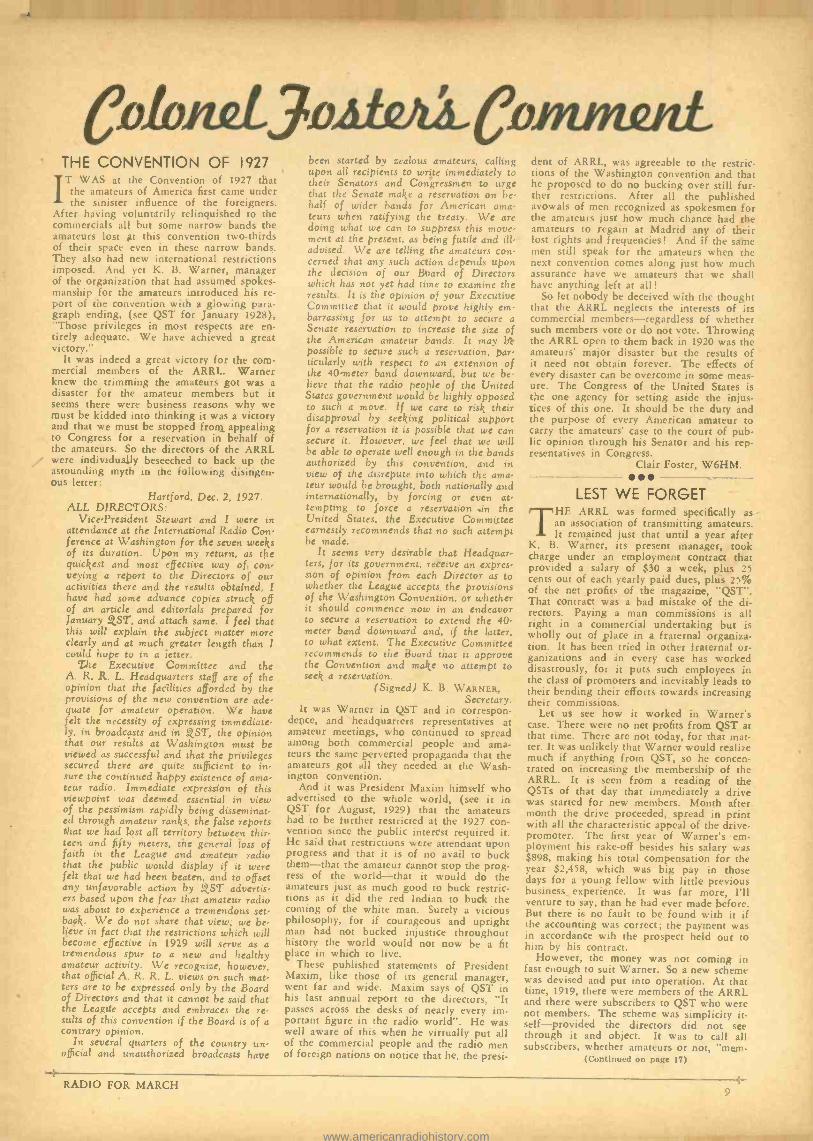
CDI oizL 3.attitai THE CONVENTION OF 1927
IT WAS at the Convention of 1927 that the amateurs of America first came under the sinister influence of the foreigners.
After having voluntarily relinquished to the commercials all but some narrow bands the amateurs lost at this convention two -thirds of their space even in these narrow bands. They also had new international restrictions imposed. And yet K. B. Warner, manager of the organization that had assumed spokes - manship for the amateurs introduced his re- port of the convention with a glowing para- graph ending, (see QST for January 1928), "Those privileges in most respects are en- tirely adequate. We have achieved a great victory."
It was indeed a great victory for the com- mercial members of the ARRL. Warner knew the trimming the amateurs got was a disaster for the amateur members but it seems there were business reasons why we must be kidded into thinking it was a victory and that we must be stopped from appealing to Congress for a reservation in behalf of the amateurs. So the directors of the ARRL were individually beseeched to back up the astounding myth in the following disingen- ous letter:
Hartford, Dec. 2, 1927. ALL DIRECTORS:
Vice -President Stewart and I were in attendance at the International Radio Con- ference at Washington for the seven weeks of its duration. Upon my return, as the quickest and most effective way of con- veying a report to the Directors of our activities there and the results obtained, I have had some advance copies struck off of an article and editorials prepared for January Q,ST, and attach same. I feel that this will explain the subject matter more clearly and at much greater length than I could hope to in a letter.
The Executive Committee and the A. R. R. L. Headquarters staff are of the opinion that the facilities afforded by the provisions of the new convention are ade- quate for amateur operation. We have felt the necessity of expressing immediate- ly, in broadcasts and in QST, the opinion that our results at Washington must be viewed as successful and that the privileges secured there are quite sufficient to in sure the continued happy existence of ama- teur radio. Immediate expression of this viewpoint was deemed essential in view of the pessimism rapidly being disseminat- ed through amateur ranks, the false reports that we had lost all territory between thir- teen and fifty meters, the general loss of faith in the League and amateur radio that the public would display if it were felt that we had been beaten, and to offset any unfavorable action by QST advertis- ers based upon the fear that amateur radio was about to experience a tremendous set- back. We do not share that view; we be- lieve in fact that the restrictions which will become effective in 1929 will serve as a tremendous spur to a new and healthy amateur activity. We recognize, however, that official A. R. R. L. views on such mat- ters are to be expressed only by the Board of Directors and that it cannot be said that the League accepts and embraces the re, suits of this convention if the Board is of a contrary opinion.
In several quarters of the country un- official and unauthorized broadcasts have
been started by zealous amateurs. calling upon all recipients to write immediately to their Senators and Congressmen to urge that the Senate make a reservation on be- half of wider bands for American ama- teurs when ratifying the treaty. We are doing what we can to suppress this move- ment at the present, as being futile and ill - advised. We are telling the amateurs con- cerned that any such action depends upon the decision of our Board of Directors which has not yet had time to examine the results. It is the opinion of your Executive Committee that it would prove highly em- barrassing for us to attempt to secure a Senate reservation to increase the size of the American amateur bands. It may be possible to secure such a reservation, par- ticularly with respect to an extension of the 40 -meter band downward, but we be- lieve that the radio people of the United States government would be highly opposed to such a move. If we care to risk their disapproval by seeking political support for a reservation it is possible that we can secure it. However, we feel that we will be able to operate well enough in the bands authorized by this convention, and in view of the disrepute into which the ama- teur would be brought, both nationally and internationally, by forcing or even at- tempting to force a reservation .in the United States, the Executive Committee earnestly recommends that no such attempt be made.
It seems very desirable that Headquar- ters, for its government, receive an expres- sion of opinion from each Director as to whether the League accepts the provisions of the Washington Convention, or whether it should commence now in an endeavor to secure a reservation to extend the 40- meter band downward and, if the latter, to what extent. The Executive Committee recommends to the Board that it approve the Convention and make no attempt to seek a reservation.
(Signed) K. B. WARNER, Secretary.
It was Warner in QST and in correspon- dence, and headquarters representatives at amateur meetings, who continued to spread among both commercial people and ama- teurs the same perverted propaganda that the amateurs got all they needed at the Wash- ington convention.
And it was President Maxim himself who advertised to the whole world, (see it in QST for August, 1929) that the amateurs had to be further restricted at the 1927 con- vention since the public interest required it. He said that restrictions were attendant upon progress and that it is of no avail to buck them -that the amateur cannot stop the prog- ress of the world -that it would do the amateurs just as much good to buck restric- tions as it did the red Indian to buck the coming of the white man. Surely a vicious philosophy, for if courageous and upright man had not bucked injustice throughout history the world would not now be a fit place in which to live.
These published statements of President Maxim, like those of its general manager, went far and wide. Maxim says of QST in his last annual report to the directors, "lt passes across the desks of nearly every im- portant figure in the radio world ". He was well aware of this when he virtually put all of the commercial people and the radio men of foreign nations on notice that he, the presi-
dent of ARRL, was agreeable to the restric- tions of the Washington convention and that he proposed to do no bucking over still fur- ther restrictions. After all the published avowals of men recognized as spokesmen for the amateurs just how much chance had the amateurs to regain at Madrid any of their lost rights and frequencies! And if the same men still speak for the amateurs when the next convention comes along just how much assurance have we amateurs that we shall have anything left at all!
So let nobody be deceived with the thought that the ARRL neglects the interests of its commercial members -regardless of whether such members vote or do not vote. Throwing the ARRL open to them back in 1920 was the amateurs' major disaster but the results of it need not obtain forever. The effects of every disaster can be overcome in some meas- ure. The Congress of the United States is the one agency for setting aside the injus- tices of this one. It should be the duty and the purpose of every American amateur to carry the amateurs' case to the court of pub- lic opinion through his Senator and his rep- resentatives in Congress.
Clair Foster, W6HM.
LEST WE FORGET THE ARRL was formed specifically as
an association of transmitting amateurs. It remained just that until a year after
K. B. Warner, its present manager, took charge under an employment contract that provided a salary of $30 a week, plus 25 cents out of each yearly paid dues, plus 25% of the net profits of the magazine, "QST ". That contract was a bad mistake of the di- rectors. Paying a man commissions is all right in a commercial undertaking but is wholly out of ,place in a fraternal organiza- tion. It has been tried in other fraternal or- ganizations and in every case has worked disastrously, for it puts such employees in the class of promoters and inevitably leads to their bending their efforts towards increasing their commissions.
Let us see how it worked in Warner's case. There were no net profits from QST at that time. There are not today, for that mat- ter. It was unlikely that Warner would realize much if anything from QST, so he concen- trated on increasing the membership of the ARRL. It is seen from a reading of the QSTs of that day that immediately a drive was started for new members. Month after month the drive proceeded, spread in print with all the characteristic appeal of the drive - promoter. The first year of Warner's em- ployment his rake -off besides his salary was $898, making his total compensation for the year $2,458, which was big pay in those days for a young fellow with little previous business experience. lt was far more, I'll venture to say, than he had ever made before. But there is no fault to be found with it if the accounting was correct; the payment was in accordance wih the prospect held out to him by his contract.
However, the money was not coming in fast enough to suit Warner. So a new scheme was devised and put into operation. At that time, 1919, there were members of the ARRL and there were subscribers to QST who were not members. The scheme was simplicity it- self- provided the directors did not see through it and object. It was to call all subscribers, whether amateurs or not, "mem-
(Continued on page 17)
RADIO FOR MARCH 9
www.americanradiohistory.com
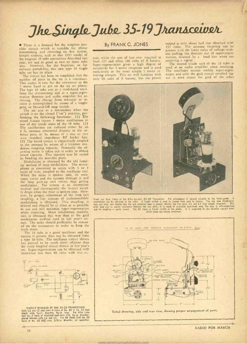
JJwSòtqkJt& 35- 19JìanAcQiviz2 There is a demand for the simplest pos-
sible circuit which is suitable for phone transmitting and receiving on five meters. Simple circuits, such as this 1935 model of the original 19 tube transceiver described last year, are not as good as two or three tube sets. However, for the beginner, or for extreme portability, this new type 19 single tube set has its place.
The circuit has been so simplified that the number of parts in the set is a minimum. This makes it easy for the newcomer to the 5 meter band to get on the air on phone. The type 19 tube acts as a modulated oscil lator for transmitting and as a super- regen- erative detector and audio amplifier for re ceiving. The change from transmit to re ceive is accomplished by means of a single pole, or On- and -Off snap switch.
The set acts as a transmitter when the switch is on the closed ( "on ") position, per forming the following functions: (1) The tuned circuit causes 5 meter oscillations in one of the triode units of the 19 tube. (2) The oscillations are radiated either by an 8 ft. antenna connected directly to the an- tenna post, or by means of a one or twr, wire matched impedance RF feeder line. (3) The tuned circuit is capacitively coupled to the antenna by means of a trimmer con- denser coupling capacity. Normally the ad justing screw is taken out in order to obtain lower capacity. This capacity may be varied by bending the movable plate.
Modulation is obtained by the old famil- iar method of loop modulation. The micro- phone is connected in series with 3 or 4
turns of wire, coupled to the oscillator coil. When the mike is spoken into, its resis- tance varies and the current through it and the loop pick -up coil varies, thus giving modulation. The system is an absorption method and consequently the output usual- ly drops when the mike is spoken into. How- ever, by proper adjustment of the loop coil coupling, a fair amount of understandable modulation is obtained. This coupling is
critical and should be as close as is possible to use and still maintain super- regeneration while receiving. More satisfactory modula- tion is obtained this way than in the grid modulation method used in last year's dr- cuit. The mike should preferably be mount- ed on the transceiver in order to keep the leads short.
The 19 tube is a good oscillator and the carrier is greater than can be obtianed from a type 30 tube. The oscillator circuit shown has proved to be much more efficient than the unity coupled circuit shown in last year's set. Super -regeneration can be obtained with somewhat less than 80 volts with this cir-
CIRCUIT DIAGRAM OF THE 35 -19 TRANSCEIVER Coils L1 and L2 each have 6 turns of No. 12 or No. 14 base
copper wire, grin. diameter, :. -in. long. The Mike Loop
Coil has 3 turns of insulated push -tack wire r,_ -in. diameter.
placed between coils Ll and L2. The RF Choke Coil has 50 turns of No. 22 DSC wire, 3 /6 -in. diameter, air supported.
-4
By FRANK C. JONES
cuit, while the one of last year required at least 135 and often 180 volts of B battery. Super -regeneration gives a high degree of sensitivity for 5 meter reception and is used exclusively in the more simple 5 meter re- ceiving circuits. This set will function with only 90 volts esf B battery, but the power
output a only about half that obtained with 135 volts. The antenna coupling can be greater with the latter value of voltage with- out pulling the detector out of super- regen- eration, denoted by a loud hiss when not receiving a signal.
The second triode unit of the 19 tube is
used as an audio amplifier when receiving. The oscillator section merely super- regen- erates and only the grid circuit rectified sig- nal is used across the grid of the other
Front and Rear Views of tine u'tia c,mcact 35 -19 mouthricce can le att csed to the make. A toggle does not shcw very clearly hcw the mik coupling loop mike loop coil is mere:y susrended Petween the two and its coupl'.nu is easily varie I. The RF choke is
which
Transceiver. The miuophone is secured directly to the front ranel. A
switch is used to change from send to receive. The rear view illustration is placed between the two coils, Ll. and L2 (see circuit diagram). This
coils; it is made of insulated push -tack wire, the loop is self -supporting rarely visible in the photo. It is asprorted on the bakelite support piece
holds the tuning condense.
TO BE USED FOR CORRECT PLACEMENT OF PARTS ONLY
Detail drawings, side and rear view, showing proper arrangement of parts.
10 RADIO FOR MARCH
www.americanradiohistory.com
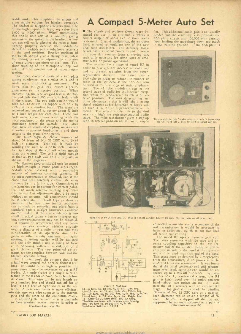
triode unit. This simplifies the circuit and gives ample volume for headset operation. The headset or telephone receivers should be of the high impedance type, any value from 1,000 to 5,000 ohms. When transmitting, this triode unit acts as a monitor, giving sidetone of the speech in the headset. A per- son can tell easily whether the mike is func- tioning properly because the modulation should be audible in the telephone receivers in the send position. Receive position of the switch should give a strong hiss, unless the tuning circuit is adjusted to a carrier of some other transmitter or oscillator. Too - close coupling of the microphone loop coil will pull the detector out of super regen- eration.
The tuned circuit consists of a two plate tuning condenser, two similar coils and a small mica grid -blocking condenser. The latter, plus the grid leak, causes super -re- generation in the receive position. When transmitting, the receiver grid leak is shorted - out and only the 2,500 ohm grid leak is left in the circuit. The two coils can be wound with No. 12 or No. 14 copper wire on a 3/8 inch rod as a winding form. The turns are removed and spaced to occupy about 34 inch to 1 inch length for each coil. These two coils make a continuous winding with the mica condenser in the center and the tuning condenser across the outside. The latter must have an insulated coupling on its shaft in order to prevent hand- capacity and short circuit to the metal front panel.
The radio- frequency choke consists of about 50 turns of No. 22 DSC wire, 3/16 inch in diameter. This coil is made by winding the wire on a 3/16 inch diameter rod and slipping the coil off when enough turns are wound. The coil is rigid enough so that its two ends will hold it in place, as shown in the diagrams.
The filament rheostat should only be turned up high enough to cause good super- regen- eration when receiving with a reasonable amount of antenna coupling capacity. If no super -regeneration is obtained, and if the circuit has been carefully checked, the trou- ble may be in a faulty tube. Connections to the batteries are important for correct polar- ity. Too much antenna coupling may cause trouble and first adjustments should be made without an antenna. All connections should be soldered and the leads kept as short as possible. The two plate tuning condenser can be made by removing one plate from a standard 3 -plate midget condenser available on the market. If the grid condenser is too small in actual capacity due to incorrect rat- ing, super -regeneration may not be obtained.
It should be remembered that any trans- ceiver radiates receiver whistles strongly over a distance of a mile or two and thus consideration in its operation should be given to other nearby amateurs. In trans-
, mitting, a strong carrier will be radiated and the only trouble one is likely to have is in obtaining sufficient modulation of a good character. The two principal adjust- ments are the coupling between coils and the filament rheostat setting.
For 5 meter work the antenna should be a half wave vertical rod or wire about 8 feet long. It should be as high as possible. In some cases it may be necessary to use a RF feeder. A simple feeder is a single wire at- tached to the 8 foot antenna, 14 inches below its center. This wire can be any length up to a hundred feet and should run off for at least 3 or 4 feet at right angles to the an- tenna. A two wire feeder is more efficient;
-in this case one wire connects to the antenna post and the other to the aluminum chasis.
In adjusting the transmitter it is desirable to have another receiver nearby in order to
(Continued on page 28)
RADIO FOR MARCH
A Compact 5 -Meter Auto Set The circuit and set here shown were de-
signed for use in an automobile where a carrier output of about two to three watts is desired. Class A modulation, driven quite hard, is used to modulate one of the new 6A6 tube oscillators. The ordinary trans- ceiver has insufficient power output to trans- mit over flat country from a moving car, such as is necessary for some types of ama- teur work or police operations.
The receiver has a stage of tuned RF in order to give a slight increase of sensitivity and to prevent radiation from the super - re ,enerative detector. The latter uses a 6A6 tube in order to reduce the number of tubes in the set because the 6A6 can also be used as the first stage of audio amplifica- tion. The 42 tube modulator acts as the second stage of audio for loudspeaker recep- tion when the sendreceive switch is on re- ceive position. The 6A6 detector has an- other advantage in that it will take a strong signal without audio distortion to better val- ue than a 37 or 76 super -regenerative de- tector. The second triode unit in the 6A6 acts as a high mu resistance -coupled audio stage. The mike transformer gives a step -up ratio in receive position for the audio ampli-
fier. This additional audio gain is not usually needed but the center -tap also prevents the 6A6 plate circuit and 100,000 ohm resistor from loading the modulator down too much in the transmit position. If the 6A6 plate is
The =hire. hr this 5 -meter auto vet is only 3 inches deep and will ea:ily fi id a Glue for it-elf in almost any car.
Inside view of the 5 -meter auto set. There is a shield partition between the coils. The four tubes are all on one shelf.
6.4.5
CIRCUIT DIAGRAM L1-6 turns, No. 12 wire, % -in. dia., T /r -in. long.
L2 -15 turns, No. 14 wire, ' /. -in. dia., 11/2-in. long.
L3 -18 turns. No. 22 DSC wire, Syr -in. long, r /; -in. dia. L4-6 turns, No. 12 wire, % -in. dia., 11/ -in. long. Tl- Center -tap 30 henry choke, 100 MA rating. 12 -Mike transforms with secondary center- tapped. RFC -60 turns No. 30 DSC wire, . -in. dia. Send- Receive Switch is a D.P.D.T.
connected across the entire secondary of the mike transformer it would be necessary to have an additional switch to cut this load off white transmitting.
The tuned RF upes a resonant grid coil. The latter resonates with the tube and an- renna coupling capacities to the low fre- quency end of the amateur band, or prefer- ably just outside of the band if the transmit- ter is to be used near that end of the band. This stage must be detuned by 2 megacycles, from the transmitter, if no power is to be absorbed from the transmitter. It was found that if the usual condenser and coil arrange- ment was used, some power would be ab- sorbed up to 3 MC off resonance. By using a very low C, semi -tuned circuit, the RF gain is fairly good over the entire amateur hand -about two points on the "R" scale over that of a receiver with an untuned RF stage. This grid coil is made by winding 18 turns of No. 22 DSC wire on a quarter - inch diameter rod to cover a length of 3i inch. The coil is slipped off the rod and supported by its ends soldered to a pair of
(Continued on page 24)
www.americanradiohistory.com
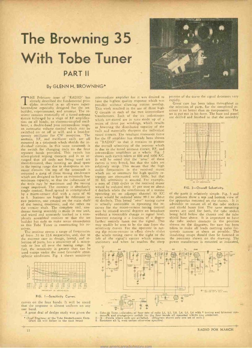
The Browning 35 With Tobe Tuner
PART II
By GLENN H. BROWNING*
THE February issue of "RADIO" has already described the fundamental prin- ciples involved in an all -wave super-
heterodyne especially designed for the set - builder, experimenter, and amateur. The re- ceiver consists essentially of a tuned -antenna circuit follovyed by a stage of RF amplifica- tion on all bands; an electron -coupled oscil- lator, a double -band pass intermediate stage, an automatic volume control which may be switched on or off at will, and a beat-fre- quency oscillator for CW reception. The antenna, RF, and oscillator coils are all mounted in a catacomb which shields the in- dividual circuits. In this same catacomb is the switch for changing coils on the four separate bands provided. This switch has silver -plated wiping contacts and is so ar- ranged that all coils not being used are short -circuited, thus insuring no dead spots in the tuning range due to absorption in res- onant circuits. On top of the catacomb is mounted a gang of three tuning condensers which are designed to have an extremely low minimum capacity, so that the inductance of the coils rRay be maximum and the tuning range improved. The receiver is absolutely single control. Band spread is accomplished by a micro -vernier dial with a ratio of 40 to 1. Stations are logged by reference to two pointers, one rotated on the main shaft of the tuning condenser, and the other on the vernier shaft. The complete coil, con- denser tuning assembly is made in one unit, and wired and accurately tracked in a com- pletely assembled receiver so that the set builder has only to make seven connections to this Tobe Tuner in constructing his re- ceiver.
The receiver covers a range of frequencies of from .55 to 22.6 megacycles, and, due to the extreme care in design, layout, and se- lection of parts, has a sensitivity of 1. micro- volt or less all over the tuning range. In fact, the sensitivity is greater than can be used except under the most favorable atmo- spheric conditions. Fig. 1 shows sensitivity
-i.1111 0_..,M40aMM \'!îDGC IS1:! ea. ro,
EpE' ' 14.9 111 111.1 '7 n Is
EUC n EG<CLES a a
FIG. I- Sensitivity Curves.
curves on the four bands. It will be noted that the response is almost uniform on any one band.
A great deal of design study was given the
Chief Engineer of the Tobe Deutschmann Corp. (Part III will follow in the next issue)
intermediate amplifier for it was desired to have the highest quality response which was possible without allowing station overlap. This work resulted in the use of three high Q circuits in each of the two intermediate transformers. Each of the six inductances which are tuned are in turn made up of a
series of three pie windings, which results in lowering the distributed capacity of the coils and materially sharpens the individual tuned circuits. The resultant resonance curve for the IF amplifier has already been shown in "RADIO" so that it remains to picture the overall selectivity of the receiver which is due to the tuned antenna circuit, RF, and intermediate amplifiers as a whole. Fig. 2
shows such curves taken at 600 and 1000 KC. It will be noted that the "nose" of these curves is very broad, but that the sides are relatively steep. This means that the high audio frequencies in the received music which are so necessary for high quality re- ception are attenuated very little, but that 10 KC selectivity is assured. For example, a note of 2500 cycles in the received music would be reduced only 37 per cent or about 4 decibels while the interference of a station operating on an adjacent channel 10 KC away would he reduced some 99.2 or about 40 decibels. This broad "nose" tuning curve is actually noticeable in operating the re- ceiver for the micro -vernier tuning control may be rotated several degrees on broadcast without a noticeable change in signal level. however rotating it a fraction of a degree farther entirely tunes out the signal. This may readily be seen to be the case from the selectivity curves. For the operator in tun- ing the micro -vernier in effect slowly slides the whole tuning curve to the right or the left of the signal's carrier which remains stationary and when he reaches the steep
portion of the curve the signal decreases very rapidly.
Great care has been taken throughout in the selection of parts, for the completed re- ceiver is no better than its components. The set is put out in kit form. The base and panel are drilled and finished so that the assembly
GO
x' 1.
iíiCi11i1CO ariaÌ 1i"nnaCl
11111111111 C 7.C- .uC CC fl111 11
111 17
ÌÌÌÌÌÌÌÌÌÌÌÌ M CC 1..1
11111111111111 Inc Of noon. MCC
1000
FIG. 2- Overall Selectivity.
of the parts is relatively simple. Fig. 3 and the pictures show a top and bottom view of the apparatus mounted on the chassis. It is advisable to mount all of the tube sockets and shield bases first. The same mounting screws are used for both, the tube socket being held below the chassis and the tube shield base above. It is important to have the tube socket contacts in the position shown on the diagrams, for care has been taken to make all leads carrying radio fre- quency current as short as possible. The insulating straps should then be fastened in the positions shown on the drawing. The power transformer is mounted as indicated,
Te, * I
se °
1 -- Tobe -$5 Tunr.- Consists of four sets of coils LI, L2. L3. L4, L5, L6 with tuning and trimmer con - dense and change -over switch for the four bands all mounted within one container.
2- X-- Points where coils are switched. (Diagram shows only one set of coils.) 3 - Resistors all % watt unless otherwise specified.
12 RADIO FOR MARCH 4-
www.americanradiohistory.com
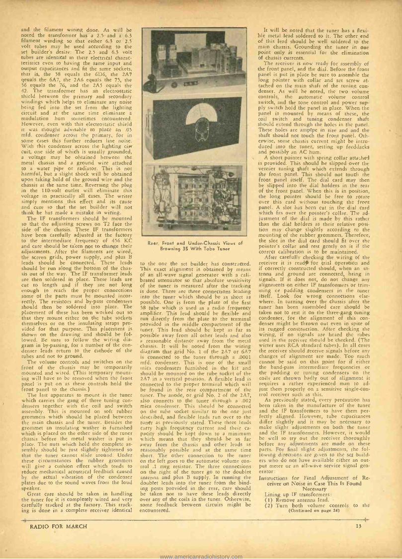
and the filament wiring done. As will be noted the transformer has a 2.5 and a 6.3 filament winding so that either 6.3 or 2.5 volt tubes may be used according to the set builder's desire. The 2.5 and 6.3 volt tubes are identical in their electrical charac- teristics even to having the same input and output capacitances and fit the same sockets, that is, the 58 equals the 6D6, the 2A7 qeuals the 6A7, the 2A6 equals the 75, the 56 equals the 76, and the 2A5 equals the 42. The transformer has an electrostatic shield between the primary and secondary windings which helps to eliminate any noise being fed into the set from the lighting circuit and at the same time eliminate a modulation hum sometimes encountered. However, even with this electrostatic shield it was thought advisable to place an .05 mfd. condenser across the primary, for in some cases this further reduces line noise. With this condenser across the lighting cir- cuit, one side of which is usually grounded, a voltage may be obtained between the metal chassis and a ground wire attached to a water pipe or radiator. This is not harmful, but a slight shock will be obtained upon taking hold of the ground wire and the chassis at the same time. Reversing the plug in the 110 -volt outlet will eliminate this voltage in practically all cases. The writer simply mentions this effect and its cause and cure so that the set builder will not think he has made a mistake in wiring.
The IF transformers should be mounted so that the adjusting screws on T2 face the side of the chassis. These IF transformers have been carefully adjusted at the factory to the intermediate frequency of 456 KC and care should be taken not to change their adjustments. After the filaments are wired, the screen grids, power supply, and plus B leads should be connected. These leads should be run along the bottom of the chas- sis out of the way. The IF transformer leads are then soldered in place. These leads are cut to length and if they are not long enough to reach the proper connections some of the parts must be mounted incor- rectly. The resistors and by -pass condensers should then be soldered into place. The placement of these has been worked out so that they mount either on the tube sockets themselves or on the insulating straps pro- vided for that purpose. This placement is shown on the drawing and should be fol- lowed. Be sure to follow the wiring dia- gram in by- passing, for a number of the con- denser leads return to the cathode of the tubes and not to ground.
The volume controls and switches on the front of the chassis may be temporarily mounted and wired. (This temporary mount- ing will have to be removed when the front panel is put on as these controls hold the front panel to the chassis.)
The last apparatus to mount is the tuner which carries the gang of three tuning con- densers together with the coil and switch assembly. This is mounted on soft rubber grommets which should be placed hetween the main chassis and the tuner. Besides the grommet an insulating washer is furnished which is placed on the other side of the tuner chassis before the metal washer is put in place. The nuts which hold the complete as- sembly should be just slightly tightened so that the tuner cannot slide around. Under these circumstances the rubber grommets will give a cushion effect which tends to reduce mechanical acoustical feedback caused by the actual vibration of the condenser plates due to the sound waves from the loud speaker.
Great care should be taken in handling the tuner for it is completely wired and very carefully tracked at the factory. This track- ing is done in a complete receiver identical
Rear, Front and Under -Chassis Views of Browning 35 With Tobe Tuner
to the one the set builder has constricted. This exact alignment is obtained by means of an all -wave signal generator with a cali- brated attenuator so that absolute sensitivity of the tuner is measured after the tracking is done. There are three connections leading into the tuner which should be as short as possible. One is from the plate of the first 58 tube which is used as a radio frequency amplifier. This lead should be flexible and run directly from the plate to the terminal provided in the middle compartment of the tuner. This lead should be kept as far as possible away from all other leads and also a reasonable distance away from the metal chassis. It will be noted from the wiring diagram that grid No. 1 of the 2A7 or 6A7 is connected to the tuner through a .0001 mfd. condenser. This is one of the small mica condensers furnished in the kit and should be mounted on the tube socket of the 2A7 in a vertical position. A flexible lead is connected to the proper terminal which will be found in the rear compartment of the tuner. The anode, or grid No. 2 of the 2A7, also connects to the tuner through a .002 mica condenser. This should be connected on the tube socket similar to the one just described, and flexible leads run over to the tuner as previously stated. These three leads carry high frequency current and their ca- pacity should be kept down to a minimum which means that they should be as far away from the chassis and other leads as reasonably possible and at the same time short. The other connection to the tuner on the left goes to the automatic volume con- trol .1 meg resistor. The three connections on the right of the tuner go to the doublet antenna and plus B supply. In running the doublet leads into the tuner from the bind- ing posts provided in the rear, care should be taken not to have these leads directly over any of the coils in the tuner. Otherwise, some feedback between circuits might be encountered.
It will be noted that the tuner has a flexi- ble metal lead soldered to it. The other end of this lead should be well soldered to the main chassis. Grounding the tuner in one point only is essential for the elimination of chassis currents.
The receiver is now ready for assembly of the front panel, and the dial. Before the front panel is put in place be sure to assemble the long pointer with collar and set screw at- tached on the main shaft of the tuning con denser. As will be noted, the two volume controls, the automatic volume control switch, and the tone control and power sup- ply switch hold the panel in place. When the panel is mounted by means of these, the coil switch and tuning condenser shaft should extend through the holes in the panel. These holes are amplpe in size and and the shaft should not touch the front panel. Oth- erwise, some chassis current might be intro- duced into the tuner, setting up feeddacks and possibly an AC hum.
A short pointer with spring collar atta_he-I is provided. This should be slipped over the vernier tuning shaft which extends through the front panel. This should not touch the front panel itself. The dial card may then be slipped into the dial holders in the rear of the front panel. When this is in position. the long pointer should be free to rotate over this card without touching the front panel. A slot has been cut in the dial card which fits over the pointer's collar. The ad- justment of the dial is made by this rather than the dial holders as their relative posi- tion may change slightly according to the mounting of the rubber grommets. Therefore, the slot in the dial card should fit over the pointer's collar and rest gently on it if the correct calibration is to be maintained.
After carefully checking the wiring of the receiver it is read, for trial operation and if correctly constructed should, when an An-
tenna and ground are connected, bring in signals. If it does not, do not change any alignments on either IF transformers or trim- ming or padding condensers in the tuner itself. Look for wrong connections else- where. In turning over the chassis after the tuner has been assembled care should be taken not to rest it on the three -gang tuning condenser, for the alignment of this con- denser might be thrown out even in spite of its rugged construction. After checking the wiring, if no signals are heard the tubes used in the receiver should be checked. (The wirter uses RCA standard tubes). In all cases the receiver should receive signals before any changes of alignment are made. Too much cannot be said on this point for if either the band -pass intermediate frequencies or the padding or tuning condensers on the coils are thrown badly out of alignment it requires a rather experienced man to ad- just them properly on a sensitive single -con- trol receiver such as this.
As previously stated, every precaution has been taken in the manufacture of the tuner and the IF transformers to have them per- fectly aligned. However, tube capacitances differ slightly and it may be necessary to make slight adjustments on both the tuner and the IF transformers. However, it would be well to try out the receiver thoroughly before any adjustments are made on these parts. For final slight adjustments, the fol- lowing directions are given to the sex build- ers who do not have available either an out- put meter or an all -wave service signal gen- erator: Instructions for Final Adjustment of Re-
ceiver on Noise in Case This Is Found Necessary
Lining up IF transformers: (1) Remove antenna lead. (2) Turn both volume controls to the
(Continued on page 34)
RADIO FOR MARCH 13
www.americanradiohistory.com
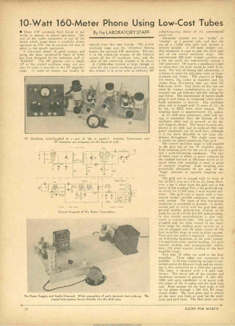
10 -Watt 160 -Meter Phone Using Low -Cost Tubes Many CW amateurs have found it too
costly to change to phone operation. The cost of the audio equipment is one of the factor which keeps many a would -be phone operator on CW, not to mention the cost of tubes in the speech equipment.
A 160 -meter phone of good output, and using the most inexpensive types of tubes has been designed by the technical staff of "RADIO ". The RF portion uses a single '47 in the crystal oscillator stage and two type 45 tubes in parallel in the RF amplifier stage. 15 watts of output can readily be
By f' -Ie LABORATORY STAFF
secured from this tube line -up. The crystal oscillator stage uses the "chirpless" keying feature for optional CW operation. The key is in the center -tap resistor of the filament circuit of the 47 oscillator tube, and the value of the center -tap resistor is 20 ohms.
A 15,000. ohm resistor is large enough in value for the crystal oscillator grid leak, and this resistor is in series wiht an ordinary HF
'47 Oscillator, Link -Coupled to a pair of '45s in parall I. Antenna Condensers and RF Ammeter are Mounted on the Panel at Left.
+P.
1,000
e.
N , POR .ION
Circuit Diagram of the Entire Transmitter.
The Power Supply and Audio Channel. Wide separation of parts prevents hum pick -up. The crystal microphone feeds directly into the 6C6 tube.
radio -frequency choke of the conventional small size.
160 -meter crystals are not "tricky" or "cranky ", as a general rule, and thus the use of a 15,000 ohm grid leak resistor is entirely suitable. A 150 mmf. midget vari- able condenser is used to tune the plate tank coil of the crystal oscillator stage. The conventional 100 mmf. midget variables are a bit too small for conveniently tuning a
160 meter coil. Of course, a condenser larger in value than 150 mmf. could be used, if de- sired. For ease of tuning and adjustment, it is better to wind the 160 -meter coils on large - diameter coil forms. The ceramic or Bake- lite forms, 21/4 inches in diameter and 31/2 inches long, four -prong type, are ideal for 160 -meter work. Coil forms of this size are made by various manufacturers, or the con- structor can use ordinary bakelite tubing for coil forms. The convenience of factory -made plug -in coil forms is evidenced when multi - band operation is desired. The oscillator plate coil is wound with 55 turns of No. 20 or No. 22 DCC wire, close wound. The winding space is approximately 21/2 inches.
A .01 mfd mica condenser, 1000 volt rat- ing, is connected from the bottom of the oscillator plate coil to ground, as the cir- cuit diagram shows. The screen by -pass con- denser is .01 mfd. and an ordinary 600 volt paper condenser can be used here, although it is far more desirable to use mica con- densers throughout. The slight extra cost is worth the added protection they give.
The crystal oscillator stage is link -coupled to the grid coil of the '45 amplifier stage. Link coupling calls for the use of a grid coil and a grid- coil -tuning condenser. The cost of these items is offset, in greát measure, by the marked increase in efficiency which is se- cured when link coupling is used in place of capacity coupling. Link coupling also practically eliminates 99 per cent of the "bugs" inherent in capacity coupling sys- tems.
The grid coil is wound with 52 turns of No. 22 DCC wire on a 2% -in. dia. form. How- ever, a tap is taken from the grid coil at the center of the winding.This is the grid -leak tap, to which the 25,000 ohm, 5 watt resistor con- nects. The grid coil -is tuned with a two - section midget variable condenser, 140 mmf. each section. The rotor of this two- section condenser is connected to ground. A closed - circuit jack in series with the grid leak and ground enables grid- current reading to be made by use of a 0 -100 MA DC milliammeter. In this circuit, neutralization is also indi- cated, as explained later. The meter can be plugged into the plate circuit of the oscil- lator stage for reading plate current, or it can be plugged into the plate circuit of the final amplifier stage to read its plate current. Thus only one meter is required. It performs the following functions, in the order named: (1) oscillator plate current reading; (2) grid current reading and neutralization indica- tion; (3) plate current reading of the final amplifier stage:
Two type 45 tubes are used in the final amplifier. These tubes are connected in parallel. A 20 ohm center -tap resistor is con- nected across the filament leads and the center - tap is then connected to a 1300 ohm resistor. The latter is shunted with a 4 mfd. con- denser. The lower side of the resistor and condenser connects to ground. A .001 mfd. 1000 volt mica condenser is in series with the plates of the 45 tubes and the final tank coil. Plate current for the final stage is fed to the plates through a 200 MA RF trans- mitter choke. The final plate coil is wound on the same size form as used for the oscil- lator and grid coils. The final plate coil has
RADIO FOR MARCH
www.americanradiohistory.com
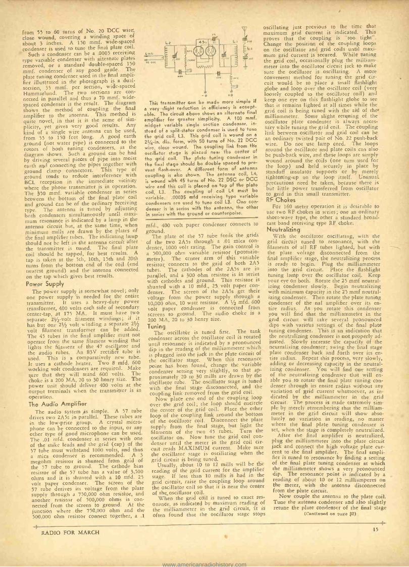
from 55 to 60 turns of No. 20 DCC wire, close wound, covering a winding space of
about 3 inches. A 150 mmf. wide -spaced condenser is used to tune the final plate coil.
Such a condenser can be a .0005 receiving type variable condenser with alternate plates removed, or a standard double -spaced 150
mmf. condenser of any good grade. The plate tuning condenser used in the final ampli- fier illustrated in the photograph is a dual - section, 35 mmf. per section, wide -spaced Hammarlund. The two sections are con-
nected in parallel and thus a 70 tnmf. wide - spaced condenser is the result. The diagram shows the method of coupling the final
amplifier to the antenna. This method is
quite novel, in that it is the acme of sim- plicity, yet gives very good results. Any kind of a single wire antenna can be used, from 55 to 150 feet long. A good earth ground (not water pipe) is connected to the rotors of both tuning condensers, as the diagram shows. Such a ground can be had by driving several pieces of pipe into moist earth and connecting the pipes together with ground clamp connectors. This type of ground tends to reduce interference with BCL reception in the immediate vicinity where the phone transmitter is in operation. The 350 mmf. variable condenser in series between the bottom of the final plate coil and ground can be of the ordinary receiving type. The antenna is tuned by adjusting both condensers simultaneously until maxi- mum resonance is indicated by a lamp in the antenna circuit but, at the same time, when minimum mills are drawn by the plates of the final amplifier tubes. The indicating lamp should not be left in the antenna circuit after the transmitter is tuned. The final plate coil should be tapped, for best results. A
tap is taken at the 5th, 10th, 15th and 20th turns from the bottom end of the coil (end nearest ground) and the antenna connected on the tap which gives best results.
Power Supply
4.14
TO CSC
D
This transmitter can be made more simple if a very slight reduction in efficiency is accept-
able. The circuit above shows an alternate final
amplifier for greater simplicity. A 100 mmf.
midget variably single section condenser, in-
stead of a split -stator condenser is used to tune
the grid coil, L3. This grid coil is wound on a
21 /4 -in. dia. form, with 50 turns of No. 22 DCC
wire, close wound. The coupling link from the
oscillator stage is placed near the center of
the grid coil. The plate tuning condenser in
the final stage should be double spaced to pre-
vent flash -over. A different form of antenna
coupling is also shown. The antenna coil, L4,
is wound with 45 turns of No. 22 DSC or DCC
wire and this coil is placed on top of the plate
coil, L3. The coupling of coil L4 must be
variable. .00035 mfd receiving type variable
condensers are used to tune coil L3. One con-
denser is in series with the antenna, the other in series with the ground or counterpoise.
The power supply is somewhat novel; only one power supply is needed for the entire transmitter. It uses a heavy -duty power transformer, 400 volts each side of secondary center -tap, at 175 MA. It must have two separate 21/2 -volt filament windings; if it has but one 21/2 volt winding a separate 21/2
volt filament transformer can be added. The 45 tubes in the final amplifier must not operate from the same filament winding that lights the filament of the 47 oscillator and the audio tubes. An 83V rectifier tube is used. This is a comparatively new tube. It uses a cathode heater. Two 8 mfd. 600 working volt condensers are required. Make sure that they will stand 600 volts. The choke is a 200 MA, 20 to 30 henry size. The power unit should deliver 400 volts at the output terminals when the transmitter is in operation. The Audio Amplifier
The audio system is simple. A 57 tube drives two 2A5s in parallel. These tubes are in the low -price group. A crystal micro- phone can be connected to the input, or any other type of good microphone can be used. The .01 mfd. condenser in series with one of the mike leads and the grid (cap) of the 57 tube must withstand 1000 volts, and thus a mica condenser is recommended. A 3
megohm resistor is shunted from grid of the 57 tube to ground. The cathode bias resistor of the 57 tube has a value of 3,500 ohms and it is shunted with a 10 mfd. 25 volt paper condenser. The screen of the 57 tube derives its voltage from the plate supply through a 750,000 ohm resistor, and another resistor of 500,000 ohms is con- nected from the screen to ground. At the junction where the 750,000 ohm and the 500,000 ohm resistor connect together, a .1
mfd., 400 volt paper condenser connects to
ground. The plate of the 57 tube feeds the grids
of the two 2A5s through a .01 mica con- denser, 1000 volt rating. The gain control is
a 500,000 ohm variable resistor (potentio- meter). The center arm of this variable resistor connects to the grid of both 2A5 tubes. The cathodes of the 2A5s are in
parallel, and a 300 ohm resistor is in series with cathodes and ground. This resistor is shunted with a 10 mfd., 25 volt paper con- denser. The screen of the 2A5s get their voltage from the power supply through a
10,000 ohm, 10 watt resistor. A 1/2 mfd. 600 volt paper condenser is connected from screens to ground. The audio choke is a
200 MA, 20 to 30 henry size.
Tuning The oscillator is tuned first. The tank
condenser across the oscillator coil is rotated until resonance is indicated by a pronounced dip in the reading of the milliammeter which is plugged into the jack in the plate circuit of
the oscillator stage. When this resonance point has been found, change the variable condenser setting very slightly, so that ap- proximately 20 to 30 mills are drawn by the oscillator tube. The oscillator stage is tuned with the final stage disconnected, and the coupling link removed from the grid coil. variation of grid current whatsoever, as in-
Now place one end of the coupling loop dicated by the milliammeter in the grid over the grid coil; the loop should encircle circuit. The process is made extremely sim-
the center of the grid coil. Place the other pie by merely remembering that the milliam- loop of the coupling link around the bottom meter in the grid circuit will show abso-
of the oscillator coil. Disconnect the plate lutely no variation
in reading, no matter supply from the final stage, but light the the final plate tuning condenser is
filaments of the two 45 tubes. Turn the set, when the stage is completely neutralized. oscillator on. Now tune the grid coil con- After the final amplifier is neutralized, denser until the meter in the grid coil cir- plug the milliammeter into the plate circuit cuit reads MAXIMUM current. Make sure jack and connect the high voltage plate cur - the oscillator stage is oscillating when the rent to the final amplifier. The final ampli- grid circuit is being tuned. fier is tuned to resonance by finding a setting
Usually, about 10 to 12 mills will be the of the final plate tuning condenser at which reading of the grid current for the amplifier the milliammeter shows a very pronounced stage. If less than 10 mills is had in the dip. The resonance point is indicated by a
grid circuit, raise the coupling loop around reading of about 10 or 12 milliamperes on
the oscillator coil so that it is near the center the meter, with the antenna disconnected of the oscillator coil. from the plate circuit.
When the grid coil is tuned to exact res- Now couple the antenna to the plate coil. onance, as indicated by maximum reading of Tune the antenna condenser and also slightly the milliammeter in the grid circuit, it is retune the plate condenser of the final stage often found that the oscillator stage stops (Continued on page 32)
oscillating just previous to the time that maximum grid current is indicated. This proves that the coupling is "too tight ". Change the position of the coupling loops on the oscillator and grid coils until maxi- mum grid current is secured. While tuning the grid coil, occasionally plug the milliam- meter into the oscillator circuit jack to make sure the oscillator is oscillating. A more convenient method for tuning the grid cir- cuit would be to place a small flashlight globe and loop over the oscillator coil (very loosely coupled to the oscillator coil) and keep one eye on this flashlight globe to see that it remains lighted at all times while the grid coil is being tuned with the aid of the milliammeter. Some slight retuning of the oscillator plate condenser is always neces- sary while tuning the grid coil. The coupling link between oscillator and grid coil can be an ordinary twisted pair of No. 22 push -back wire. Do not use lamp cord. The loops around the oscillator and plate coils can also be push -back wire, and these loops are simply wound around the coils (one turn used for the loop) and held securely in place by standoff insulator supports or by merely tightening -up on the loop itself. Unusual precautions need be taken, because there is but little power transferred from oscillator to grid in this small transmitter. RF Chokes
For 160 meter operation it is desirable to use two RF chokes in series; one an ordinary short -wave type, the other a standard broad- cast band receiving type RF choke. Neutralizing
With the oscillator oscillating, with the grid circuit tuned to resonance, with the filaments of all RF tubes lighted, but with the plate voltage disconnected from the final amplifier stage, the neutralizing process is ready to begin. Plug the milliammeter into the grid circuit. Place the flashlight tuning lamp over the oscillator coil. Keep your eye on both. Rotate the 25 mmf neutral- izing condenser slowly. Begin neutralizing with minimum capacity in the 25 mmf neutral- izing condenser. Then rotate the plate tuning condenser of the nal amplifier over its en- tire radius. As you rotate this condenser you will find that the milliammeter in the grid circuit will take several pronounced dips with various settings of the final plate tuning condenser. This is an indication that the neutralizing condenser is not properly ad- justed. Slowly increase the capacity of the neutralizing condenser; swing the final stage plate condenser back and forth over its en- tire radius. Repeat this process, very slowly, adding or decreasing capacity in the neutral- izing condenser. You will find one setting of the neutralizing condenser that will en- able you to rotate the final plate tuning con- denser through its entire radius without any
RADIO FOR MARCH 15
www.americanradiohistory.com
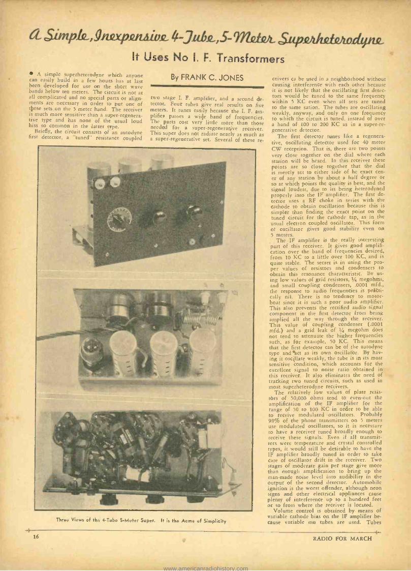
CL Simp.Gc,gnap.eniiiv,E 4-31,tk,5- Supivzhsiondync It Uses No I. F. Transformers
A simple superheterodyne which anyone can easily build in a few hours has at last been developed for use cat the short wave bands below ten meters. The circuit is not at all complicated and no special parts or align- ments are necessary in order to put one of these sets on the 5 meter band. The receiver is much more sensitive than a super- regenera- tive type and has none of the usual loud hiss so common in the latter type.
Briefly, the circuit consists of an autodyne first detector, a "tuned" r esistance coupled
By FRANK C. JONES
two stage I. F. amplifier, and a second de- tector_ Four tubes give real results on five meters. It tunes easily because the I. F. am- plifies passes a wide band of frequencies. The parts cost very little more than those needed for a super -regenerative receiver. This super does not radiate nearly as much as a super -regenerative set. Several of these re-
-t- 16
Three Views of t.ie 4 -Tube S -Meter Super. I- is the Acme of Simplicity
ceivers ca be used in a neighborhood without causing interference with each other because it is not likely that the oscillating first detec- tors would he tuned to the same frequency within 5 KC even when all sets are tuned to the same sation. The tubes are oscillating weakly, anyway, and only on one frequency to which the circuit is tuned, instead of over a band of 100 to 200 KC as in a super -re- generative detector.
The first detector tunes like a regenera- tive, oscillating detector used for 40 meter CW reception. That is, there are two points very close together on the dial where each station will be heard. In this receiver these points are so close together that the dial is merely set to either side of he exact cen- er of any station by about a half degree or so at which points the quality is best, and the signal loudest, due to its being heterodyned properly into the IF amplifier. The first de- tector uses a RF choke in series with the cathode to obtain oscillation because this is simpler than finding the exact point on the tuned circuit for the cathode tap, as in the usual electron coupled oscillator. This form of oscillator gives good stability even on 5 meters.
The IF amplifier is the really interesting part of this receiver. It gives good amplifi- cation over the band of frequencies desired, from 10 KC to a little over 100 KC, and is quite stable. The secret is in using the pro- per values of resistors and condensers to obtain this resonance characteristic. By us- ing low values of grid resistors, 1/4 megohms, and small coupling condensers, .0001 mfd., the response to audio frequencies is practi- cally nil. There is no tendency to motor- boat since it is such a poor audio amplifier. This also prevents the rectified audio signal component in the first detector from being implied all the way through the receiver. This value of coupling condenser (.0001 mfd.) and a grid leak of 1/4 megohm does not tend to attenuate the higher frequencies such, as for example, 50 KC. This means that the first detector can be of the autodyne type and *act as its own oscillator. By hav- ing it oscillate weakly, the tube is in its most sensitive condition, which accounts for the excellent signal to noise ratio obtained in this receiver. It also eliminates the need of tracking two tuned circuits, such as used in most superheterodyne receivers.
The relatively low values of plate resis- tors of 50,000 ohms tend to even -out the amplification of the IF amplifier for the range of 50 to 100 KC in order to be able to receive modulated oscillators. Probably 98% of the phone transmitters on 5 meters use modulated oscillators, so it is necessary to have a receiver tuned broadly enough to receive these signals. Even if all transmit- ters were temperature and crystal controlled types, it would still be desirable to have the IF amplifier broadly tuned in order to take care of oscillator drift in the receiver. Two stages of moderate gain per stage give more than enough amplification to bring up the man -made noise level into audibility in the output of the second detector. Automobile ignition is the worst offender, although neon signs and other electrical appliances cause plenty of interference up to a hundred feet or so from where the receiver is located.
Volume control is obtained by means of variable cathode bias on the IF amplifier be- cause variable mu tubes are used. Tubes
RADIO FOR MARCH
www.americanradiohistory.com
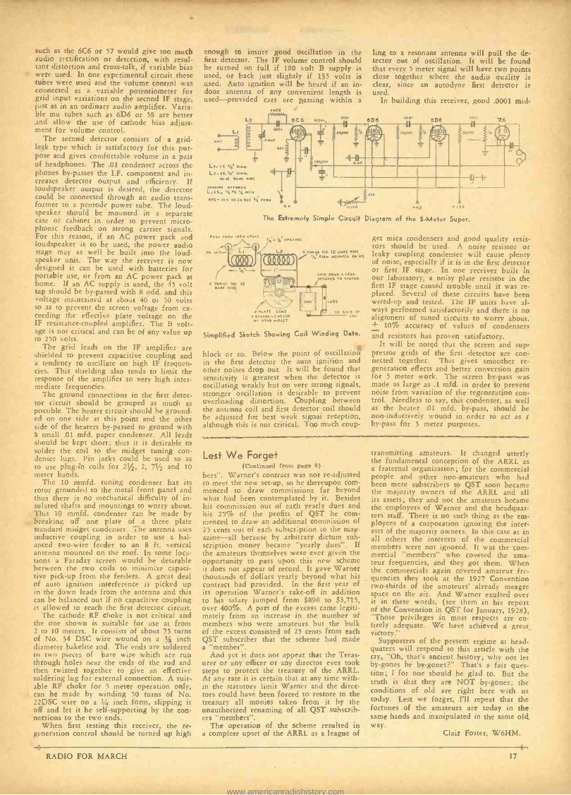
such as the 6C6 or 57 would give too much audio rectification or detection, with resul- tant distortion and cross -talk, if variable bias were used. In one experimental circuit these tubes were used and the volume control was connected as a variable potentiometer for grid input variations on the second IF stage, just as in an ordinary audio amplifier. Varia- ble mu tubes such as 6D6 or 58 are better and allow the use of cathode bias adjust- ment for volume control.
The second detector consists of a grid - leak type which is satisfactory for this pur- pose and gives comfortable volume in a pair of headphones. The .01 condenser across the phones by- passes the I.F. component and in- creases detector output and efficiency. If loudspeaker output is desired, the detector could be connected through an audio trans- former to a pentode power tube. The loud- speaker should be mounted in a separate case or cabinet in order to prevent micro - phonic feedback on strong carrier signals. For this reason, if an AC power pack and loudspeaker is to be used, the power audio stage may as well be built into the loud- speaker unit. The way the receiver is now designed it can be used with batteries for portable use, or from an AC power pack at home. If an AC supply is used, the 45 volt tap should be by- passed with 8 mfd. and this voltage maintained at about 40 or 50 volts so as to prevent the screen voltage from ex- ceeding the effective plate voltage on the IF resistance -coupled amplifier. The B volt- age is not critical and can be of any value up to 250 volts.
The grid leads on the IF amplifier are shielded to prevent capacitive coupling and a tendency to oscillate on high IF frequen- cies. This shielding also tends to limit the response of the amplifier to very high inter- mediate frequencies.
The ground connections in the first detec- tor circuit should be grouped as much as possible. The heater circuit should be ground- ed on one side at this point and the other side of the heaters by- passed to ground with a small .01 mfd. paper condenser. All leads should be kept short; thus it is desirable to solder the coil to the midget tuning con- denser lugs. Pin jacks could be used so as to use plug -ìn coils for 21/2, 2, 71/2 and 10 meter bands.
The 10 mmfd. tuning condenser has its rotor grounded to the metal front panel and thus there is no mechanical difficulty of in- sulated shafts and mountings to worry about. This 10 mmfd. condenser can be made by breaking off one plate of a three plate standard midget condenser. The antenna uses inductive coupling in order to use a bal- anced two -wire feeder to an 8 ft. vertical antenna mounted on the roof. In some loca- tions a Faraday screen would be desirable between the two coils to minimize capaci- tive pick -up from the feeders. A great deal of auto ignition interference is picked up in the down leads from the antenna and this can be balanced out if no capacitive coupling is allowed to reach the first detector circuit.
The cathode RF choke is not critical and the one shown is suitable for use at from 2 to 10 meters. It consists of about 75 turns of No. 34 DSC wire wound on a 3/g inch diameter bakelite rod. The ends are soldered to two pieces of bare wire which are run through holes near the ends of the rod and then twisted together to give an effective soldering lug for external connection. A suit- able RF choke for 5 meter operation only, can be made by winding 50 turns of No. 22DSC wire on a t/4 inch form, slipping it off and let it be self -supporting by the con- nections to the two ends.
When first testing this receiver, the re- generation control should he turned up high
enough to insure good oscillation in the first detector. The IF volume control should be turned on full if 180 volt B supply is used, or back just slightly if 135 volts is used. Auto ignition will be heard if an in- door antenna of any convenient length is used -provided cars are passing within a
ling to a resonant antenna will pull the de- tector out of oscillation. It will be found that every 5 meter signal will have two points close together where the audio quality is clear, since an autodyne first detector is used.
In building this receiver, good .0001 mid-
The Extremely Simple Circuit Diagram of the 5 -Meter Super.
,,ri 7..t1 ,,.,w.,0..
Simplified Sketch Showing Coil Winding Data.
block or so. Below the point of oscillatioñ in the first detector the auto ignition and other noises drop out. It will be found that sensitivity is greatest when the detector is oscillating weakly but on very strong signals, stronger oscillation is desirable to prevent overloading distortion. Coupling between the antenna coil and first detector coil should be adjusted for best weak signal reception, although this is not critical. Too much coup-
get mica condensers and good quality resis- tors should be used. A noisy resistor or leaky coupling condenser will cause plenty of noise, especially if it is in the first detector or first IF stage. In one receiver built in our laboratory, a noisy plate resistor in the first IF stage caused trouble until it was re- placed. Several of these circuits have been wired -up and tested. The IF units have al- ways performed satisfactorily and there is no alignment of tuned circuits to worry about. + 10% accuracy of values of condensers and resistors has proven satisfactory.
It will be noted that the screen and sup- pressor grids of the first detector are con- nected together. This gives smoother re- generation effects and better conversion gain for 5 meter work. The screen by -pass was made as large as .1 mfd. in order to prevent noise from variation of the regeneration con- trol. Needless to say, this condenser, as well as the heater .01 mfd. by -pass, should be non -inductively wound in order to act as t by -pass for 5 meter purposes.
Lest We Forget (Continued from page 9)
bers ". Warner's contract was not re- adjusted to meet the new set -up, so he thereupon com- menced to draw commissions far beyond what had been contemplated by it. Besides his commission out of each yearly dues and his 25% of the profits of QST he com- menced to draw an additional commission of 25 cents out of each subscription to the mag- azine -all because by arbitrary dictum sub- scription money became "yearly dues ". If the amateurs themselves were ever given the opportunity to pass upon this new scheme it does not appear of record. It gave Warner thousands of dollars yearly beyond what his contract had provided. In the first year of its operation Warner's rake -off in addition to his salary jumped from $898 to $3,715, over 400%. A part of the excess came legiti- mately from an increase in the number of members who were amateurs but the bulk of the excess consisted of 25 cents from each QST subscriber that the scheme had made a "member ".
And yet it does not appear that the Treas- urer or any officer or any director ever took steps to protect the treasury of the ARRL. At any rate it is certain that at any time with- in the statutory limit Warner and the direc- tors could have been forced to restore to the treasury all monies taken from it by the unauthorized renaming of all QST subscrib- ers "members ".
The operation of the scheme resulted in a complete upset of the ARRL as a league of
transmitting amateurs. It changed utterly the fundamental conception of the ARRL as a fraternal organization; for the commercial people and other non -amateurs who had been mere subscribers to QST soon became the majority owners of the ARRL and all its assets; they and not the amateurs became the employers of Warner and the headquar- ters staff. There is no such thing as the em- ployees of a corporation ignoring the inter- ests of the majority owners. In this case as in all others the interests of the commercial members were not ignored. It was the com- mercial "members" who coveted the ama- teur frequencies, and they got them. When the commercials again coveted amateur fre- quencies they took at the 1927 Convention two- thirds of the amateurs' already meagre space on the air. And Warner exulted over it in these words, (see them in his report of the Convention in QST for January, 1928), "Those privileges in most respects are en- tirely adequate. We have achieved a great victory."
Supporters of the present regime at head - quaters will respond to this article with the cry, "Oh, that's ancient history; why not let by -gones be by- gones ?" That's a fair ques- tion; I for one should be glad to. But the truth is that they are NOT by- gones; the conditions of old are right here with us today. Lest we forget, I'll repeat that the fortunes of the amateurs are today in the same hands and manipulated in the same old way.
Clair Foster, W6HM.
RADIO FOR MARCH 17
www.americanradiohistory.com
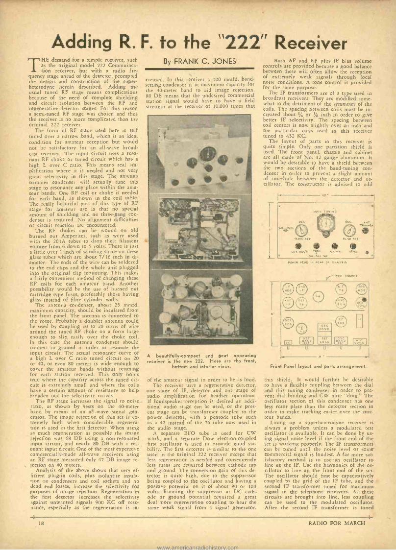
Adding R. F. to the "222" Receiver THE demand for a simple receiver, such
as the original model 222 Commuinca- tion receiver, but with a radio fre-
quency stage ahead of the detector, prompted the design and construction of the super- heterodyne herein described. Adding the usual tuned RF stage means complications because of the need of complete shielding and circuit isolation between the RF and regenerative detector stages. For this reason a semi -tuned RF stage was chosen and thus the receiver is no more complicated than the original 222 receiver.
The form of RF stage used here is self tuned over a narrow band, which is an ideal condition for amateur reception but would not be satisfactory for an all -wave broad- cast receiver. The input circuit uses a reso- nant RF choke or tuned circuit which has a
high L over C ratio. This means real am- plification where it is needed and not very great selectivity in this stage. The antenna trimmer condenser will actually tune this stage to resonance any place within the ama- teur bands. One RF coil or choke is needed for each band, as shown in the coil table. The really beautiful part of this type of RF stage for amateur use is that no special amount of shielding and no three -gang con- denser is required. No alignment difficulties or circuit reaction are encountered.
The RF chokes can be wound on old burned out Amperites, such as were used with the 201A tubes to drop their filament voltage from 6 down to 5 volts. There is just a little over 1 inch of winding space on these glass tubes which are about 7/16 inch in di- ameter. The ends of the wire can be soldered to the end clips and the whole unit plugged into the original clip mounting. This makes a fairly convenient method of changing these RF coils for each amateur band. Another possibility would be the use of burned out cartridge type fuses, preferably those having glass instead of fibre cylinder walls.
The antenna condenser, about 25 mmfd. maximum capacity, should be insulated from the front panel. The antenna is connected to the rotor. Probably a doublet antenna could be used by coupling 10 to 20 turns of wire around the tuned RF choke on a form large enough to slip, easily over the choke coil. In this case the antenna condenser should connect to ground in order to resonate the input circuit. The actual resonance curve of a high L over C ratio tuned circuit on 20 or 40, or even 80 meters is wide enough to cover the amateur bands without retuning for each station received. This only holds true where the capacity across the tuned cir- cuit is extremely small and where the coils have a certain amount of resistance to help broaden out the selectivity curves.
The RF stage increases the signal to noise ratio, as shown by tests on the 40 -meter band by means of an all -wave signal gen- erator. The image rejection of this set is ex- tremely high when considerable regenera- tion is used in the first detector. When using as much regeneration as possible the image rejection was 68 DB using a non- resonated input circuit, and nearly 80 DB with a res- onant input circuit. One of the most expensive commercially -made all -wave receivers using an RF stage measured only 47 DB image re- jection on 40 meters.
Analysis of the above shows that very ef- ficient plug -in coils, plus isolantite insula- tion on condensers and coil sockets and no dead end losses, increase the selectivity for purposes of image rejection. Regeneration in the first detector increases the selectivity against unwanted signals 900 KC off reso- nance, especially as the regeneration is in-
By FRANK C. JONES
created. In this rcLeiset a 100 mmfd. band - setting condenser is at maximum capacity for the 40 -meter band to aid image rejection. 80 DB means that the undesired commercial station signal would have to have a field strength at the receiver of 10,000 times that
A beautifully- compact and neat appearing receiver is the new 222. Here are the front,
bottom and interior views.
of the amateur signal in order to be as loud. The receiver uses a regenerative detector,
one stage of IF, detector and one stage of audio amplification for headset operation. If loudspeaker reception is desired an addi- tional audio stage can be used, or the pres- ent stage can be transformer coupled to the power detector, with a pentode tube such as a 42 instead of the 76 tube now used in the audio stage.
A separate BFO tube is used for CW work, and a separate Dow electron -coupled first oscillator is used to provide good sta- bility. The first detector is similar to the one used in the original 222 receiver except that less regeneration is needed and consequently less turns are required between cathode tap and ground. The conversion gain of this de- tector is quite high, due to the suppressor being coupled to the oscillator and having a positive potential on it of about 90 or 100 volts. Running the suppressor at DC cath- ode or ground potential required a great deal more regeneration coupling to hear the same weak signal from a signal generator.
Both AF and RF plus IF bias volume controls are provided because a good balance between these will often allow the reception of extremely weak signals through local noise conditions. A tone control is provided for the same purpose.
The IF transformers are of a type used in broadcast receivers. They are modified some- what to the detriment of the symmetry of the coils. The spacing between coils must be in- creased about 1/4 or 3/g inch in order to give better IF selectivity. The spacing between coil centers is now slightly over an inch and the particular coils used in this receiver tuned to 432 KC.
The layout of parts in this receiver is quite simple. Only one partition shield is used. The front panel, chassis and cabinet are all made of No. 12 gauge aluminum. It would be desirable to have a shield between the two sections of the band -tuning con- denser in order to prevent a slight amount of interlock between the detector and os- cillator. The constructor is advised to add
r 12-
POWER PLUG IN REAR OF CHASSIS
POWER SOCKET
u
ose Bi END
LI
ANT CONO
u
Front Panel layout and parts arrangement.
this shield. It would further be desirable to have a flexible coupling between the dial and this tuning condenser in order to pre- vent dial binding and CW note "drag." The oscillator section of this condenser has one less rotor plate than the detector section in order to make tracking easier over the ama- teur bands.
Lining up a superheterodyne receiver is always a problem unless a modulated test oscillator is available. It can be done by us- ing signal noise level if the front end of the set is working properly. The IF transformers can be tuned until the noise level or some commercial signal is loudest. A far more sat- isfactory method is to use an ocsillator to line up the IF. Use the harmonics of the os- cillator to line up the front end of the set. The oscillator should first be capacitatively coupled to the grid of the IF tube, and the second IF transformer tuned for maximum signal in the telephone receivers. As these circuits are brought into line, less coupling can be used to the modulated oscillator. After the second IF transformer is tuned
18 RADIO FOR MARCH
www.americanradiohistory.com
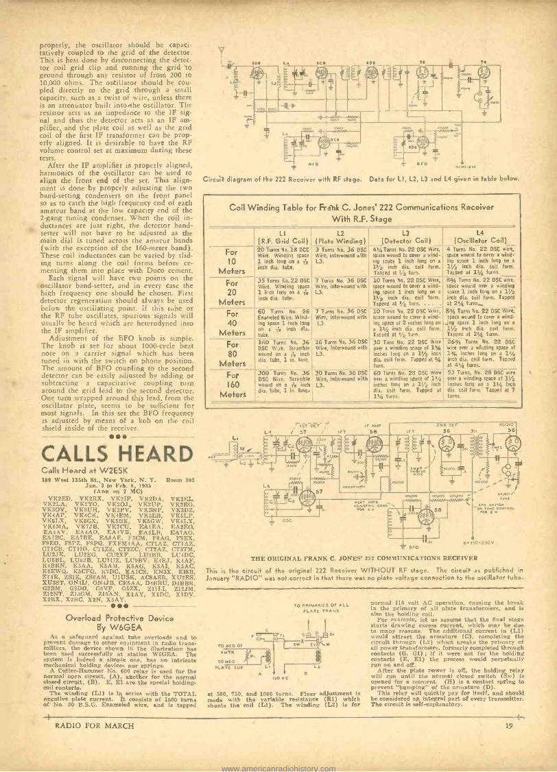
properly, the oscillator should be capaci- tatively coupled to the grid of the detector. This is best done by disconnecting the detec- tor coil grid clip and running the grid to ground through any resistor of from 200 to 10,000 ohms. The oscillator should be cou- pled directly to the grid through a small capacity, such as a twist of wire, unless there is an attenuator built into the oscillator. The resistor acts as an impedance to the IF sig- nal and thus the detector acts as an IF am- plifier, and the plate coil as well as the grid coil of the first IF transformer can be prop- erly aligned. It is desirable to have the RF volume control set at maximum during these tests.
After the IF amplifier is properly aligned, harmonics of the oscillator can he used to align the front end of the set. This align- ment is done by properly adjusting the two band -setting condensers on the front panel so as to catch the high frequency end of each amateur band at the low capacity end of the 2 -gang tuning condenser. When the coil in- ductances are just right, the detector band - setter will not have to be adjusted as the main dial is tuned across the amaeur bands (with the exception of the 160 -meter band). These coil inductances can be varied by slid- ing turns along the coil forms before ce- menting them into place with Duco cement.
Each signal will have two points on the oscillator hand -setter, and in every case the high frequency one should be chosen. First detector regeneration should always be used below the oscillating point. If this tube or the RF tube oscillates, spurious signals will usually be heard which are heterodyned into the IF amplifier.
Adjustment of the BFO knob is simple. The knob is set for about 1000 -cycle beat note on a carrier signal which has been tuned in with the switch on phone position. The amount of BFO coupling to the second detector can be easily adjusted by adding or subtracting a capacitative coupling turn around the grid lead to the second detector. One turn wrapped around this lead, from the oscillator plate, seems to be sufficient for most signals. In this set the BFO frequency is adjusted by means of a kob on the coil shield inside of the receiver.
Nro
Circuit diagram of the 222 Receiver with RF stage.
ero
Data for LI, L2, L3 and
.,eo-z;o
L4 given in table below.
Coil Winding Table for Frank C. Jones' 222 Communications Receiver With R.F. Stage
For 10
Meters For 20
Meters For 40
Meters For 80
Meters For 160
Meters
LI (R.F. Grid Coil) 20 Turns No.18 DCC Wire. Winding state 1. inch long on a is inch dia. tube.
35 Turns No.22 DSC
Wire. Winding space 1 inch long on aie inch dia. tube.
60 Turns No. 26 Enameled Wire. Wind- ing space 1 inch hng on a ,Ta inch dia. tute. 160 Turns No. .36 DSC Ware. Scramble wound on a ,Ta inch dia. tute, 1 in. long.
300 Turns No. 36 DSC Wire. Scramble wound on a ,Ta inch dia. tube, 1 in. long.
L2 ( Plate Winding )
3 Turns No, 36 DSC Wire, interwound with L3.
7 Tunis No. 36 DSC Wire, interwound with L3.
7 Turns No. 36 DSC Wire, interwound with L3.
16 Turns No. 36 DSC
Wire, interwound with l3.
30 Turns No. 36 DSC Wire, interwound with U.
L3 (Detector Coil)
41!, Turns No.22 DSC Wire, space wound to cover a wind- ing space 1 inch long on a
1' inch dia. coil form.
Tap-led at 3 turn.
10 Turns No. 22 DSC Wire, space wound to cover a wind- ing space 1 inch long on a
11,2 inch dia. coil form. Tapped at T; turn. .. 10 Turns No. 22 DSC Wire, space wound to ewer a wind- ing space of 2 inches long on
a l',_ inch dia. coil form. Tapped at ' turn.
30 Tuns No. 22 DSC Wire over a winding space of 1% inches long on a 15/2 inch dia. coil form. Tapped at % turn. 60 Turns No. 28 DSC Wire over a winding space of 1vA2
inches long on a 11/2 inch dia. coil form. Tapped at
turns.
L4 (Oscillator Coil)
4 Turns No. 22 DSC wire, space wound to cover a wind- ing space 1 inch long en a
11/2 inch dia. coil form. Tapped at 15:, turns.
8'y, Turns No. 22 DSC wire, space wound over a winding space 1 inch long on a 11/2 inch dia. coil form. Tapped at 2% turns.
8 :y, Turns No. 22 DSC Wire, space wound to cover a wind- ing space 1 inch long on a
11/2 inch dia. coil form. Tapped at 2', turns.
26y, Turns No. 22 DSC wile over a winding space of 1% inches long on a 11/2 inch dia. coil form. Tapped at 4% turns.
53 Turns. No, 28 DSC wire over a winding space of 11 /2 incises long on a 11/2 inch dia. coil form. Tapped at 7 turns.
CALLS HEARD LI-1 L3
L,
" IST DET 4 i 57 r irT
5 00
Calls Heard at W2ESK 180 West 135th St., New York, N. Y. Room 302
Jan. 3 to Feb. 8, 1935 (Ann on 7 MC)
VK2ED, VK2RX, VK2IF, VK2DA, VK2EL, VK2LA, VK2YO, VK2OJ, VK2UP, VK3F.G, VK3OV, VK3UH, VK3PV, VK3NP, VK3DZ, VK4AP, VKICK, VK4F.M, VKGLB, VK6LP, VK5T.X, VK5GX, VK5BK, VK5GW, VK6LY, VK6MA, VK7JB, VK7CU, EAIEA, EA3EQ, EA4AV, EA4AO, EA4VB, F.A6LB, EA7AO,
EA7BC, EA7BE, EARAE, F3CM, FRAG, F8EX, FREO, FSPZ, F8PQ, FXFM4AA, CT1AZ, CT1A7., CT1CB, CT1I0, CT17.Z, CT2ZC, CT2AZ, CT3TM, LU2JF., L1T2F.G, CU2XF, LU3BB, LU4DC, LU5BL, LU6JB, LU7UZ, LU9BV, K4RJ, K4AF, K4BRN, K5AA, K6AM, K5AG, K5AL K5AC, K6EWQ, K5CFQ, K7DC, KA1CS, KN3X, EIBB, ZT1R, ZS1Z, ZS6AM, U1USK, ACRASR, XU2ES, XU3ST, ON4IJ, ON4JB, CE5AA, D4BBU, D4BBR, G2BM, G2DO, G6VP, G6ZX, ZI1LI, Z12JM, Z12NT, Z13GM. Z13AN, X1AY, X1DC, XIDV, X2I1X, X2BC, X2N, X5AY.
Overload Protective Device By W6GEA
As a safeguard against tube overloads and to prevent damage to other equipment in radio trans- mitters, the device shown in the illustration has been used successfully at station W6GEA. The system is indeed a simple one, has no intricate mechanical holding devices nor springs.
A Cutler -Hammer No. 600 relay is used for the normal open circuit, (A), another for the normal closed circuit, (B). E, El are the special holding - coil contacts.
The winding (LI) is in series with the TOTAL negative plate current. It consists of 1500 turns of No. 30 B.S.G. Enameled wire, and is tapped
1 2004 ,
sopao
C
OíG
B.150-200V
THE ORIGINAL FRANK C. JONES' 222 ('OMMI"NICATIONS RECEIVER
This is the circuit of the original 222 Receiver WITHOUT RF stage. The circuit as published in
January "RADIO" was not correct in that there was no plate voltage connection to the oscillator tube.
TO NEG Of n1TR
TO NEG PLATE SUP
TO PRIMARIES Of ALL PLATE TRANS
L.
A 10 AG
L2 a
at 500, 750, and 1000 turns. Finer adjustment is made with the variable resistance (R1) which shunts the coil (L1). The winding (L2) is for
normal 110 volt AC operation, causing the brenk in the primary of all plate transformers, and is also the holding coil.
For example, let us assume that the final stage starts drawing excess current, which may be due to many reasons. The additional current in (LI) would attract the armature (C), completing the circuit through (L2) which breaks the primary of all power transformers, formerly completed through contacts (G. GI) ; if it were not for the holding contacts (E, El) the process would perpetually run on and off.
After the plate power is off, the holding relay will run until the normal closed switch (Sw) is opened for a moment. (H) is a contact spring to prevent "bumping" of the armature (D).
This relay will quickly pay for itself, and should be considered an integral part of every transmitter. The circuit is self -explanatory.
RADIO FOR MARCH 19
www.americanradiohistory.com
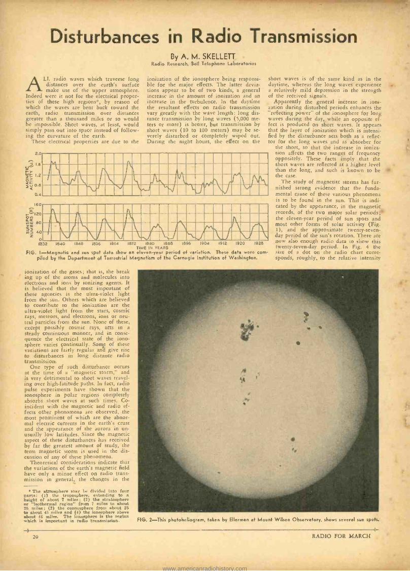
Disturbances in Radio Transmission
AALL radio waves which traverse long distances over the earth's surface make use of the upper atmosphere.
Indeed were it not for the electrical proper- ties of these high regions *, by reason of which the waves are bent back toward the earth, radio transmission over distances greater than a thousand miles or so would be impossible. Short waves, at least, would simply pass out into space instead of follow- ing the curvature of the earth.
These electrical properties are due to the
1.2
0.8
04
160
o 1832 1840 1848 1856 1064 1872 1880 1888
TIME IN YEARS FIG. I- Magnetic and sun spot data show an eleven -year period of variation. These data were corn -
piled by the Department of Terrestrial Magnetism of the Carnegie Institution of Washington.
By A. M. SKELLETT Radio Research, Bell Telephone Laboratories
ionization of the ionosphere being responsi- ble for the major effects. The latter devia- tions appear to be of two kinds, a general increase in the amount of ionization and an increase in the turbulence. In the daytime the resultant effects on radio transmission vary greatly with the wave length: long dis- tance transmission by long waves (5,000 me- ters or more) is better, but transmission by short waves (10 to 100 meters) may be se- verely disturbed or completely wiped out. During the night hours, the effect on the
. , .'I\V/, :11w17!11,. T iliriJ\J`II
short waves is of the same kind as in the daytime, whereas the long waves experience .. a relatively mild depression in the strength of the received signals.
Apparently the general increase in ioni- zation during disturbed periods enhances the "reflecting power" of the ionosphere for long waves during the day, while an opposite ef- fect is produced on short waves. It appears that the layer of ionization which is intensi- fied by the disturbance acts both as a reflec- tor for the long waves and as absorber for
the short, so that the increase in ioniza- tion affects the two ranges of frequency oppositely. These facts imply that the short waves are reflected at a higher level than the long, and such is known to be the case.
The study of magnetite storms has fur- nished strong evidence that the funda- mental cause of these various phenomena is to be found in the sun. This is indi- cated by the appearance, in the magnetic records, of the two major solar periods; the eleven -year period of sun spots and most other forms of solar activity (Fig. 1), and the approximate twenty- seven- day period of the sun's rotation. There are now also enough radio data to show this twenty- seven -day period. In Fig. 4 the size of a dot on the radio chart corre- sponds, roughly, to the relative intensity
I, . rl f i1rr CrrNWr !.I IMIIM`UJ`.1I \ II ̀ .%\ 1896 1904 1912 1920 1928
ionization of the gases; that is, the break ing up of the atoms and molecules into electrons and ions by ionizing agents. It is believed that the most important of these agencies is the ultra -violet light from the sun. Others which are believed to contribute to the ionization are the ultra -violet light from the stars, cosmic rays, meteors, and electrons, ions or neu- tral particles from the sun. None of these, except possibly cosmic rays, acts in a steady continuous manner, and in conse- quence the electrical state of the iono- sphere varies continually. Some of these variations are fairly regular and give rise to disturbances in long distance radio transmission.
One type of such disturbance occurs at the time of a "magnetic storm," and is very detrimental to short waves travel- ing over high -latitude paths. In fact, radio pulse experiments have shown that the ionosphere in polar regions completely absorbs short waves at such times. Co- incident with the magnetic and radio ef- fects other phenomena are observed, the most prominent of which are the abnor- mal electric currents in the earth's crust and the appearance of the aurora in un- usually low latitudes. Since the magnetic aspect of these disturbances has received by far the greatest amount of study, the term magnetic storm is used in the dis- cussion of any of these phenomena.
Theoretical considerations indicate that the variations of the earth's magnetic field have only a minor effect on radio trans- mission in general, the changes in the
The atmosphere may be divided into four parts: (1) the troposphere, extending to a height of about 7 miles; (2) the stratosphere or "isothermal region" from 7 miles to about 25 miles ; (2) the ozonosphere from about 25 to about 45 miles and (4) the ionosphere above about 45 miles. The ionosphere is the region which is important in radio transmission. FIG. 2 -This photoheliogrem, taken by Ellerman at Mount Wilson Observatory, shows several sun spots.
RADIO FOR MARCH
4
www.americanradiohistory.com
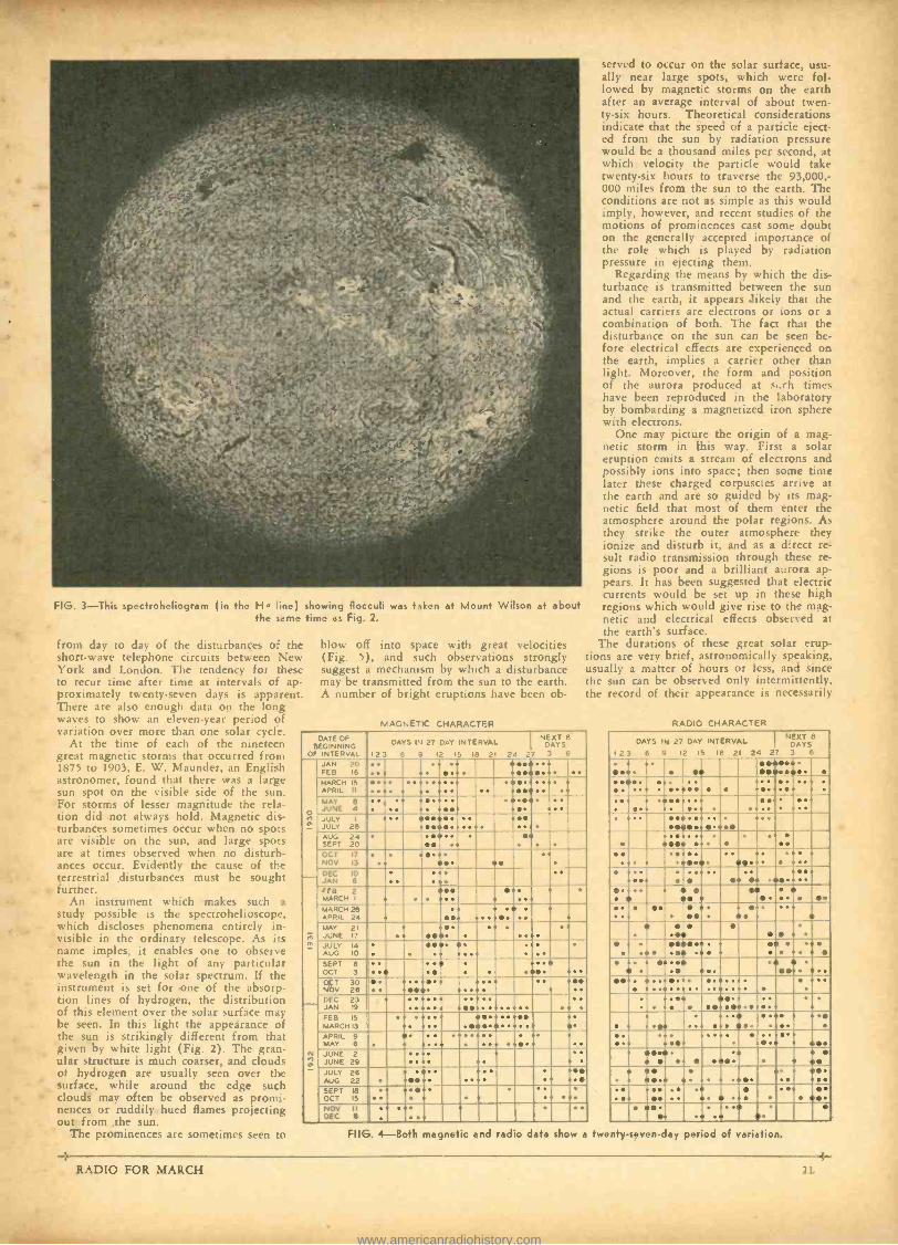
FIG. 3 -This spectroheliogram (in the Ha pine) showing flocculi was taken et Mount Wilson at about the same time as Fig. 2.
from day to day of the disturbances of the short -wave telephone circuits between New York and London. The tendency for these to recur time after time at intervals of ap- proximately twenty -seven days is apparent. There are also enough data on the long waves to show an eleven -year period of variation over more than one solar cycle.
At the time of each of the nineteen great magnetic storms that occurred from 1875 to 1903, E. W. Maunder, an English astronomer, found that there was a large sun spot on the visible side of the sun. For storms of lesser magnitude the rela- tion did not always hold. Magnetic dis- turbances sometimes occur when no spots are visible on the sun, and large spots are at times observed when no disturb- ances occur. Evidently the cause of the terrestrial disturbances must be sought further.
An instrument which makes such a study possible is the spectrohelioscope, which discloses phenomena entirely in- visible in the ordinary telescope. As its name imples, it enables one to observe the sun in the light of any particular wavelength in the solar spectrum. If the instrument is set for one of the absorp- tion lines of hydrogen, the distribution of this element over the solar surface may be seen. In this light the appearance of the sun is strikingly different from that given by white light (Fig. 2). The gran- ular structure is much coarser, and clouds of hydrogen are usually seen over the surface, while around the edge such clouds may often be observed as promi- nences or ruddily hued flames projecting out from the sun.
The prominences are sometimes seen to
-t
blow off into space with great velocities (Fig. 5), and such observations strongly suggest a mechanism by which a disturbance may be transmitted from the sun to the earth. A number of bright eruptions have been ob-
MAGNETIC CHARACTER
served to occur on the solar surface, usu- ally near large spots, which were fol- lowed by magnetic storms on the earth after an average interval of about twen- ty -six hours. Theoretical considerations indicate that the speed of a particle eject- ed from the sun by radiation pressure would be a thousand miles per second, at which velocity the particle would take twenty -six hours to traverse the 93,000,- 000 miles from the sun to the earth. The conditions are not as simple as this would imply, however, and recent studies of the motions of prominences cast some doubt on the generally accepted importance of the role which is played by radiation pressure in ejecting them.
Regarding the means by which the dis- turbance is transmitted between the sun and the earth, it appears likely that the actual carriers are electrons or ions or a combination of both. The fact that the disturbance on the sun can be seen be- fore electrical effects are experienced on the earth, implies a carrier other than light. Moreover, the form and position of the aurora produced at s.rh times have been reproduced in the laboratory by bombarding a magnetized iron sphere with electrons.
One may picture the origin of a mag- netic storm in this way. First a solar eruption emits a stream of electrons and possibly ions into space; then so.ne time later these charged corpuscles arrive at the earth and are so guided by its mag- netic field that most of them enter the atmosphere around the polar regions. As they strike the outer atmosphere they ionize and disturb it, and as a direct re- sult radio transmission through these re- gions is poor and a brilliant aurora ap- pears. It has been suggested that electric currents would be set up in these high regions which would give rise to the mag- netic and electrical effects observed at the earth's surface.
The durations of these great solar erup- tions are very brief, astronomically speaking, usually a matter of hours or less, and since the sun can be observed only intermittently, the record of their appearance is necessarily
DATE OF BEGINNING
OF INTERVAL
NEXT 8 DAYS IN 27 DAY INTERVAL DAYS
123 6 9 12 IS 18 21 24 27 3 6
a
JFAENO 26 ;i!ii!i ii CILH II? iiiii IV;
MAY e JUNE 4 i iili ii ' i i jE! ' 1 JULY 29 AUG 24 SEPT 20
HA OCT 17
NOV 13
min !i i DEC 10 JAN 6
E FEB MARCH
2 i! i INiliii! ii Sill ii MARCH 28
APRIL 24 !i ili MAY 171
JULY 14 AUG IO
: ! EISEN Ilia OCT
36 IBM BEIM EN= NOV 26 ": ialii i iiiiii DEC 23 JAN 19 ii iiii!! I FEB MARCH
15
13 M$E iiliii!!ii !i! EERIE !! ! Ell !i
:
.
!E1
MPRIL 6
iiEMI JUNE 2 JUNE 29
AUG 26
SEPT 18
OCT 15 iiii ! III
NOV II DEC 8 .
RADIO CHARACTER
DAYS i11 27 DAY INTERVAL NEXT 8 DArs
i 23 6 9 12 IS 18 21 24 27 3 6
e a i! ee E! iiii ii .
ii .. Eii iiiii iii '
IN i! ' REEL iliii i : :
: . '
E iii!i'iii ' I I - ! sni 6ii ' e e iiEi!im iiHii
e !ii!!M!! se
. ii Eii .
11111111.: iilii liEii MEE MEE i!FI!!iliiiiBE EMI i! ii!!!!!
' iii* i MEN
' FIIG. 4 -Both magnetic and radio data show a twenty- seven -day period of variation.
RADIO FOR MARCH 21
www.americanradiohistory.com
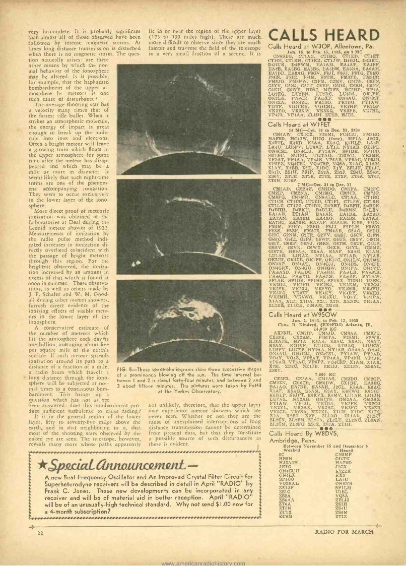
p111.111111111prig.:.1011.01+..4S/16*.
very incomplete. It is probably significant that almost all of those observed have been followed by intense magnetic storms. At times long distance transmission is disturbed when there is no magnetic storm. The ques- tion naturally arises: are there other means by which the nor- mal behavior of the ionosphere may be altered. Is it possible, for example, that the haphazard bombardment of the upper at- mosphere by meteors is one such cause of disturbance?
The average shooting star has a velocity many times that of the fastest rifle bullet. When it strikes an atmospheric molecule, the energy of impact is great enough to break up the mole- cule into ions and electrons. Often a bright meteor will leave a glowing train which floats in the upper atmosphere for some time after the meteor has disap- peared and which may be a mile or more in diameter. It seems likely that such night -time trains are one of the phenom- ena accompanying ionization. They seem to occur exclusively in the lower layer of the iono- sphere.
More direct proof of meteoric ionization was obtained at the Laboratories at Deal during the Leonid meteor shower of 1932. Measurements of ionization by the radio pulse method indi- cated increases in ionization di- rectly overhead coincident with the passage of bright meteors through this region. For the brightest observed, the ioniza- tion increased by an amount in excess of that which is found at noon in summer. These observa- tions, as well as others made by J. P. Schafer and W. M. Good- all during other meteor showers, furnish direct evidence of the ionizing effects of visible mete- ors in the lower layer of the ionosphere.
A conservative estimate of the number of meteors which hit the atmosphere each day is one billion, averaging about five per square mile of the earth's surface. If each meteor spreads ionization around its path to a distance of a fraction of a mile, a radio beam which travels a long distance through the iono- sphere will be subjected at nor- mal times to a continuous bom- bardment. This brings up a question which has not as yet been answered: does this bombardment pro- duce sufficient turbulence to cause fading?
It is in the general region of the lower layer, fifty to seventy -five miles above the earth, and in that neighboring to it, that most of the shooting stars observed by the naked eye are seen. The telescope, however, reveals many more whose paths apparertly
lie in or near the region of the upper layer (175 to 190 miles high). These are much more difficult to observe since they are much fainter and traverse the field of the telescope in a very small fraction of a second. It is
FIG. 5 -These spectroheliograms show three successive stages of a prominence blowing off the sun. The time interval be- tween I and 2 is about forty -four minutes, and between 2 and 3 about fifteen minutes. The pictures were taken by Pettit
a' the Yerkes Observatory.
not unlikely, therefore, that the upper layer may experience meteor showers which are never seen. Whether or not they are the cause of unexplained interruptions of long distance transmission cannot be determined from present data, but that they constitute a possible source of such disturbances as these is evident.
*sixeciaLannounumni. A new Beat -Frequency Os:Mator and An Improved Crystal Filter Circuit for Superheterodyne receivers wi'I be described in detail in April "RADIO" by Frank C. Jones. These new developments can be incorporated in any receiver and will be of material aid in better reception. April "RADIO" will be of an unusually -high technical standard. Why not send $ I.00 now for a 4 -month subscription?
s s
s s
CALLS HEARD Calls Heard at W3OP, Allentown, Pa.
Jan. 15, to Feb. 15, 1935, on 7 MC CN8SEG, CP1AG. CT1BQ, CT1ED, CT1ET,
Cr10I. CTIKN, CT1KR, CT1JW, D4BJL, D4BKU, D4BUK, D4BWM, EA1AM, EA4AP, EA4BF, EA4B, EA5BG, EA5BS, EA5BM, EA5BA, EA6AM, EA7BD, EABAG, FSGV, FSJI, F8JJ, F8TQ, FSEO, FRCS, F8RI, F8IM, F8TM, FM3FB, FM8CR, FMSJO, FM8PW, C2FM, C2MV, G5CW, G5FN, GSYV, G6NJ, G6CI', G6VP, G60X, G6RH, G6NF, G6KU, G6WY, HB9J, MC1FS, HC2HP, HP1A, LU2EG, LU2EN, LU2RC, LU5BL, OK1PK, OK2LK, PAcbXF, ON4AU, ON4MT, ON4ZA, ON4ZQ, PK1BO, PK1BO, PY1AW, TI2TF, VQ4CRH, VQ4CRL, VK2HF, VK2QP, VK2YO, VK3XW, VK3XQ. VK3FB, VK7HL, VP4JL, VP4AA, ZL1DI, ''LUID, 11JD2.
Calls Heard at W I FET 14 MC-Oct. 31 to Dec. 31, 1934
CM6AW, CX1CX, F3SMI, FC4CJJ, FMSBG, HAFSD, HC1JW, HI7G (fone), HP1A, J2GX, K4BTL, K4KD, K5AA, K5AC, K6HLP, LA3R, LA4U, LU5FV, LU6AP, LY1J, NY1AB, OE3FL, ON4CSL, ON4CJJ, PY1AW, SP1DE, SP1CO, SUIEC, SU1SG, TI2TAO, TI3WD, VK3MR, VP2AT, VP4AA, VP4JR, VP5AB, VPSAC, VP6JB, VP5PZ, VQ4CRL, VQ4CRP, VQ8A, X1AG, X1AM, X1AY, RIBS, X1D, X1DC, X1Y, ZF1JF, ZE1JJ,
.7,S1D, ZSIH, Zc1P, 7.S2A, 7.S2J, ZS4U, ZS6M, ZS6V, ZT1H. ZT1R, ZT1Z, ZT2F, ZT6A, ZT6J, ZT6N. ZU6P.
7 MC-Oct. 31 to Dec. 31 CM2AD, CM2AF, CM2DO, CM2FA, CM2FC,
CM2IP, CM2NA, CM2MG, CM7CX, CM7JP, CM8PQ, CN8MR, CNBALC, CP1AA, Cl'1BG, CT1CB, CT1CC, CT1ED, CTIFI, CT1JW, CP1KR, CT1L7.. CT17.7., CT2BK, D4BBT, D4BFH, D4BGK, D4BHH, D4BKU, D4BLU, D4BNN, D4LBV, EAIAE, ET1AN, EA1AR, EA1BA, EA2AD, ,EA3AN, EA3EG, EA4AO, EA5BS, EA7AH, EA7RC, FA7BE, EA8AF, EA8AH, EISB, F3CX, F3DM, F3FY, F8EO, FSJJ, FSPLM, F8WO, F8ZE, F87.F, FM3JZ. FM4AB, G2AO, G2DU, G2IC, G2NM, G2TR, G2VV, G5BJ, G5CV, G5FN, G5HC, GSLI, G5PJ, G5WP, G5US, G5YV, G6GM, G6IY. G6KP, G6NJ, G6RS. G6TM, G6UF, G6US, G6RV, C6VK, G6WY, G6XR, G6YL, C15MZ, GI6TK, 11B9Ach, KSAA. K5AF, K5AG, K6AM, I.U1AB, LU7AZ, NY1AA, NY1AB, NY2AB, 0E7JH, OK1CB, OKIFF, OK1JC, OK1LN, OK2MS, ON4AP, ON4AU, ON4CJJ, ON4DS, ON4FE, ON4GRX, ON4CU, ON4GW, ON4PA, ON4VC, PArAASD, PA¿,DC, PAmHG, PA0LR, PAmMR, PAmQL, PAmYG, PAmZM, PActZP, PY1AW, SPIAR, SP1D3, SP1HN, SP1KX, TI2RU, U3EN, VK20A, VK2FD, VK2KJ, VK2KM, VK2OJ, VK2SK, VK2XJ, VK2YO, VK3MR, VK3YU, VK3XQ, VK'7.F, VK4KY, VK4RY, VK5HG, !VKSMH, 1/K5WG, VK5XU, VO8Y, VP5'PA, X1AX, X1D, X1DA, X2C, X2N, XZN2C, YR5AA, 7.L2BZ, ZL4CK, 7.S6AM, ZU6B.
Calls Heard at W9SOW Jan. 1. 1935, to Feb. 12, 1935
Chas. B. Kindred, (EX9FDJ) Atlanta, Ill. 14,000 KC
AX7RH, CM2IP, CM5JD, CM6AA, CM8PQ, CX1FB, CX2AM, F3MTA, F3SMI, F8WK, HJ3AJH, HP1A, K5AA, K5AC, K5AN, K5AT, K5AY, K7DVF, LU4DQ, LU5AQ, LU51:W, LUSFV, LU7F.F, NYIAA, NY1AB, OA4AA, OA4J, ON4AU, ON4C1J, ON4CSL. PY1AW, PY9AD, VO4Y, VO4Z, VP2AT, VP4AA. VP4FH, VP4JR, VP5AB. VP5AC. VP6PZ, VQ4CRP, X1AM, X1AX, X2Ii, ZD2C, 'LE1JB, ZE1JJ, ZEIJN, ZS6AL, ZS6V.
7,000 KC CE3EL, CF.5AA, CM2AS, CM2DO, CM2OP,
CM2ZN, CM6CR, CM6DW, CX1BU, E,A3EG, FA4AO, EA 7 BE. EA8AH, J2CL, K5AA, K5AC, K5AF K5AG, K5AM. K5AY, K6EWQ, K6GQF, K6HLP, K6JPT, K6KVX. K6MV, LU1AB, LU1JH, LU7AZ. NY2AB, OM17R, OM2AA, OM2RX, PY1AW, VP4JL, VK2DA, VK2FK, VK20J, VK2YL, VKúAX, VK3BG, VK3FG, VK3ZB, VKSGL. VK6SA. VK7XL, X1CM, X1DC, X1FQ, X2A, X2BJ X2V, ZL1AO, ZL1AR, 7.L2CI, ZL2CY, ZL2FN, ZL2JA. ZL2LT, 7.L2NC, ZL3AN, ZL3CM, ZL3FG, ZSIZ, ZS2A, ZT1H.
Calls Heard By W8DVS, Ambridge, Penn.
Retwecn November 15 and December 6 Worked Heard
SC CNSMP HB9N .'I6TK ITJ3AJH HAFSD J2HC J2CX ON4CUU K7ZZK ON4LX KX3 SP1CO LA4U VQ3BAL OH8NB 7.F1JF SP1LM 7.S1C U1BL ZS2A VQ8A ZS6AA ZE1JJ 7.T6A ZS1H ZT6N ZS4U 7.U1X ZS6M ZU6M ZT1Z
} 4- 22 RADIO FOR MARCH
www.americanradiohistory.com
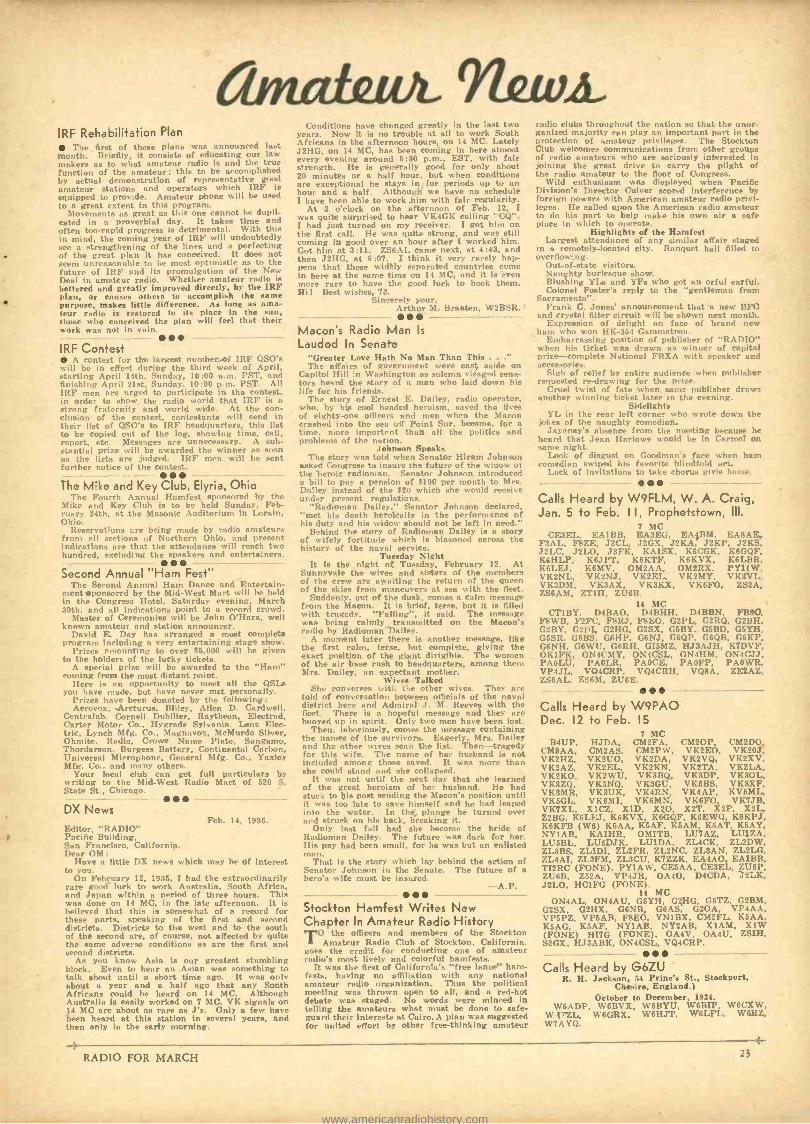
IRF Rehabilitation Plan The first of these plans was announced last
month. Brieflly, it consists of educating our law makers as to what amateur radio is and the true function of the amateur; this to be accomplished by actual demonstration of representative good amateur stations and operators which IRF is equipped to provide. Amateur phone will be used to a great extent in this program.
Movements as great as this one cannot be dupli- cated in a proverbial day. It takes time and often too -rapid progress is detrimental. With this in mind, the coming year of IRF will undoubtedly see a strengthening of the lines and a perfecting of the great plan it has conceived. It does not seem unreasonable to be most optimistic as to the future of IRF and its promulgation of the New Deal in amateur radio. Whether amateur radio is bettered and greatly improved directly, by the IRF plan, or causes others to accomplish the same purpose, makes little difference. As long as ama- teur radio is restored to its place in the sun, those who conceived the plan will feel that their work was not in vain.
IRF Contest A contest for the largest number of IRF QSO's
will be in effe-t during the third week of April, starting April 14th, Sunday, 10:00 a.m. PST. and finishing April 21st, Sunday. 10:00 p.m. PST. All IRF men are urged to participate in the contest. in order to show the radio world that IRF is a strong fraternity and world wide. At the con- clusion of the contest, contestants will send in their list of QSO's to IRF headquarters, this list to he copied out of the log. showing time. call, report, etc. Messages are unnecessary. A sub- stantial prize will be awarded the winner as soon as the lists are judged. IRF men will be sent further notice of the contest.
The M'ke and Key Club, Elyria, Ohio The Fourth Annual Hamfest sponsored by the
Mike and Key Club is to he held Sunday. Feb- ruary 24th, at the Masonic Auditorium in Lorain, Ohio.
Reservations are being made by radio amateurs from all sections of Northern Ohio, and present indications are that the attendance will reach two hundred. excluding the speakers and entertainers.
Second Annual "Ham Fest" The Second Annual Ham Dance and Entertain-
ment aponsored by the Mid -West Mart will be held in the Congress Hotel, Saturday evening. March 30th, and all indications point to a record crowd.
Master of Ceremonies will be John O'Hara, well known amateur and station announcer.
David E. Day has arranged a most complete program including a very entertaining stage show.
Prizes amounting to over $5,000 will be given to the holders of the lucky tickets.
A special prize will be awarded to the "Ham" coming from the most distant point.
Here is an opportunity to meet all the QSLs you have made, but have never met personally.
Prizes have been donated by the following: Aerovox, Arcturus, Bliley, Allen D. Cardwell,
Centralab, Cornell Dubilier, Raytheon. Electrad, Carter Motor Co., Hygrade Sylvania. Lenz Elec- tric, Lynch Mfg. Co., Magnavox, McMurdo Silver, Ohmite. Radio, Crowe Name Plate, Sangamo, Thordarson. Burgess Battery, Continental Carbon, Universal Microphone, General Mfg. Co., Yaxley Mfg. Co.. and many others.
Your local club can get full particulars by writing to the Mid -West Radio Mart of 520 S. State St., Chicago.
DX News Feb. 14, 1935.
Editor, "RADIO" Pacific Building, San Francisco, California. Dear OM:
Have a little DX news which may be of interest to you.
On February 12. 1935, I had the extraordinarily rare good lurk to work Australia, South Africa, and Japan within a period of three hours. This was done on 14 MC, in the late afternoon. It is believed that this is somewhat of a record for these parts. speaking of the first and second districts. Districts to the west and to the south of the second are, of course, not affected by quite the same adverse conditions as are the first and second districts.
As you know Asia is our greatest stumbling block. Even to hear an Asian was something to talk about until a short time ago. It was only about a year and a half ago that any South Africans could be heard on 14 MC. Although Australia is easily worked on 7 MC, VK signals on 14 MC are about as rare as J'a. Only a few have been heard at this station in several years, and then only in the early morning.
-4
Conditions have changed greatly in the last two years. Now it is no trouble at all to work South Africans in the afternoon hours, on 14 MC. Lately .1211G, on 14 MC, has been coming in here almost every evening around 5 :30 p.m., EST, with fair strength. He is generally good for only about 20 minutes or a half hour, but when conditions are exceptional he stays in for periods up to an hour and a half. Althougli we have no schedule I have been able to work .him with fair regularity.
At 3 o'clock on the afternoon of Feb. 12, I was quite surprised to hear VK4GK calling "CQ ". I had just turned on my receiver. I got him on the first call. He was quite strong, and was still coming in good over an hour after I worked him. Got him at 3:11. ZS6AL carne next, at 4:43, and then J2HG, at 6 :07. I think it very rarely hap- pens that these widely separated countries come in here at the same time on 14 MC, and it is even more rare to have the good luck to hook them. Hi l Best wishes, 73.
Sincerely your, Arthur M. Braaten, W2BSR.'
Macon's Radio Man Is
Lauded In Senate "Greater Love Hath No Man Than This .
The affairs of government were cast aside on Capitol Hill in Washington ns solemn visaged sens- tors heard the story of a man who laid down his life for his friends.
The story of Ernest E. Dailey, radio operator, who, by his cool headed heroism, saved the lives of eighty -one officers and men when the Macon crashed into the sea off Point Sur, become, for a time, more import' nt than all the politics and problems of the nation.
Johnson Speaks The story was told when Senator Hiram Johnson
asked Congress to insure the future of the widow of the heroic radioman. Senator Johnson introduced a bill to pay a pension of $100 per month to Mrs. Dailey instead of the $20 which she would receive under present regulations.
"Radioman Dailey," Senator Johnson declared, "met his death heroically in the performance of his duty and his widow should not be left in need."
Behind the story of Radioman Dailey is a story of wifely fortitude which is blazoned across the history of the naval service.
Tuesday Night It is the night of Tuesday, February 12. At
Sunnyvale the wives and sisters of the members of the crew are awaiting the return of the queen of the skies from maneuvers at sea with the fleet.
Suddenly. out of the dusk, comes a calm message from the Macon. It is brief, terse, but it is filled with tragedy. "Falling ", it said. The message was being calmly transmitted on the Macon's radio by Radioman'Dailey.
A moment later there is another message, like the first calm, terse, but complete, giving the exact position of the giant dirigible. The women of the air base rush to headquarters, among them Mrs. Dailey, an expectant mother.
Wives Talked She converses with the other wives. They are
told of conversation between officials of the naval district here and Admiral J. M. Reeves with the fleet. There is a hopeful message and they are buoyed up in spirit. Only two men have been lost.
Then, laboriously, comes the message containing the names of the survivors. Eagerly, Mrs. Dailey and the other wives scan the list. Then -- tragedy for this wife. The name of her husband is not included among those saved. It was more than she could stand and she collapsed.
It was not until the next day that she learned of the great heroism of her husband. He had stuck to his post sending the Macon's position until it was too late to save himself and he had leaped into the water. In the, plunge he turned over and struck on his back, breaking it.
Only last fall had she become the bride of Radioman Dailey. The future was dark for her. His pay had been small, for he was but an enlisted man.
That is the story which lay behind the action of Senator Johnson in the Senate. The future of a hero's wife must be insured.
-A.P. -
Stockton Hamfest Writes New Chapter In Amateur Radio History
TO the officers and members of the Stockton Amateur Radio Club of Stockton, California.
goes the credit for conducting one of amateur radio's most lively and colorful hamfests.
It was the first of California's "free lance" ham - fests, having no affiliation with any national amateur radio organization. Thus the political meeting was thrown open to all, and a red -hot debate was staged. No words were minced in telling the amateurs what must be done to safe- guard their interests at Cairo. A plan was suggested for united effort by other free -thinking amateur
radio clubs throughout the nation so that the unor- ganized majority can play an important part in the Protection of amateur privileges. The Stockton Club welcomes communications from other groups of radio amateurs who are seriously interested in joining the great drive to carry the plight of the radio amateur to the floor of Congress.
Wild enthusiasm was displayed when Pacific Division's Director Culver scored interference by foreign powers with American amateur radio privi- leges. He called upon the American radio amateur to do his part to help make his own air a safe place in which to operate.
Highlights of the Hamfest Largest attendance of any similar affair staged
in a remotely -located city. Banquet hall filled to overflowing.
Out -of -state visitors. Naughty burlesque show. Blushing YLs and YFs who got an orful earful. Colonel Foster's reply to the "gentleman from
Sacramento ". Frank C. Jones' announcement that a new BFO
and crystal filter circuit will be shown next month. Expression of delight on face of brand new
ham who won HK -354 Gammatron. Embarrassing position of publisher of "RADIO"
when his ticket was drawn as winner of capital prize- complete National FBXA with speaker and accessories.
Sigh of relief by entire audience when publisher requested re- drawing for the prize.
Cruel twist of fate when same publisher draws another winning ticket later in the evening.
Sidelights YL in the rear left corner who wrote down the
jokes of the naughty comedian. Jayenay's absence from the meeting because he
heard that Jean Harlowe would be in Carmel on same night.
Look of disgust on Goodman's face when ham comedian swiped his favorite blindfold act.
Lack of invitations to take chorus girls home.
Calls Heard by W9FLM, W. A. Craig, Jan. 5 to Feb. I I, Prophetstown, Ill.
7 M(' CF.3EL, EA1BB, EA3F.G, F,A96M, EA8AE,
F3AL, F87.E, J2CL, J2GX, J2KA, J2KP, J2KS, J2LC, J2LO, J3FK, KAI.SX, K6CGK, K6GQF, K6HLP, K6JPT, K6KTF, K6KVX, K6LBR, K6LEJ, K6MV, OM2AA, OM2RX, PY1(W, VK2NL, VK2NJ, VK2EL, VK2MY, VK3VL, VK3DM, VK3AX, VK3KX, VK6FO, ZS2A, ZS6AM, ZT1H, ZU6B.
14 MC CT1BY. D4BAO, D4BHH, D4BBN, FBBC,
FMB, F2FC, FBRJ, F8E0, G2PL, G2RQ, G2BH, G2BY, G2DI, G2HG, G2SX, G6BY, G5BD, G5YH, G5SR. G6BS, G6HP, G6NJ, G6QP, G6QB, G6KP, G6NH. G6WU, G6RH, GI5MZ, HJ3AJH, K7DVF, OKIFK, ON4CMY, ON4CSL, ON4HM, ON4CJJ, PAOLU, PAOLA, PAOCE, PAOFP, PAOWR, VP4JL, VQ4CRP, VQ4CRH, VQBA, ZE2AZ, ZS6AL. ZS6M, ZUGE. --.. - . ..
-
Calls Heard by W9PAO Dec. 12 to Feb. 15
7 MC B4UP, HJDA, CM2FA, CM20P, CM2DO,
CM8AA, CM2AS, CM2PW, VK2EO, VK20J, VK2H7., VK2UO, VK2DA, VK2VQ, VK2XV, VK2AZ, VK2EL, VK2KN, VK2TA, VK2LA, VK2KO, VK2WU, VK3BQ, VK3DP, VK3OL, VK3ZQ, VK3NQ, VK3GU, VK3BS, VK3XF, VK3MR, VK3UK, VK4RN, VK4AP, KV6ML, VK5GL, VK6MI, VK6MN, VK6FO, VK7JB, VK7XL, X1CZ, X1D, X20, X2T, X2F, X2L, Z2BG, K6LEJ, K6KVX, K6GQF, K6EWQ, K6KPJ, K6KFB (W6) K5AA, K5AF, KSAM, K5AT, K6AY, NY1AB, KA1HR, OMITB, LU7AZ, LU1ZA, LiJ6RL, LU6DJK, LU1DA, ZL4CK, ZL2DW, 7.L3BS, ZL1DI, 7.L2FR, ZL2NC, 7.L3AN, ZL2LG, 7.L4AI, ZL3FM, ZL3CU, K7ZZK, EA4AO, EA1BB, TI2RC (FONE), PY1AW, CE5AA, CE3F.L, U6P, ZU6B, 7.52A, VP4JR, OA4O, D4CDA, -J 2LK, J2LO, HC1FG (FONE).
14 MC ON4AL, ON4AU, GSYH, G2HG, G5TZ, G2BM,
G2SX, G2HX, G6NB. G6AS, G2OA, VP4AA, VP5PZ, VP5AB, F8EO, YN1BX, CM2FL, K5AA, K5AG, K5AF, NY1AB. NY2AB, X1AM, X1W (FONE) 11I7G (FONE), OA4V, OA4U, ZS1H, S2GX, HJ3ABK, ON4CSL, VQ4CRP.
Calls Heard by G6ZU R. II. Jackson, 54 l'riné St., Stockport,
Chesire, England.) October to December, 1934.
W6ADP, W6BVX, W6BYU, W6BIP, W6CXW, W W6GRX, W6HJT, W6LFL, W6RZ, W 7 A YQ.
RADIO FOR MARCH 23
www.americanradiohistory.com
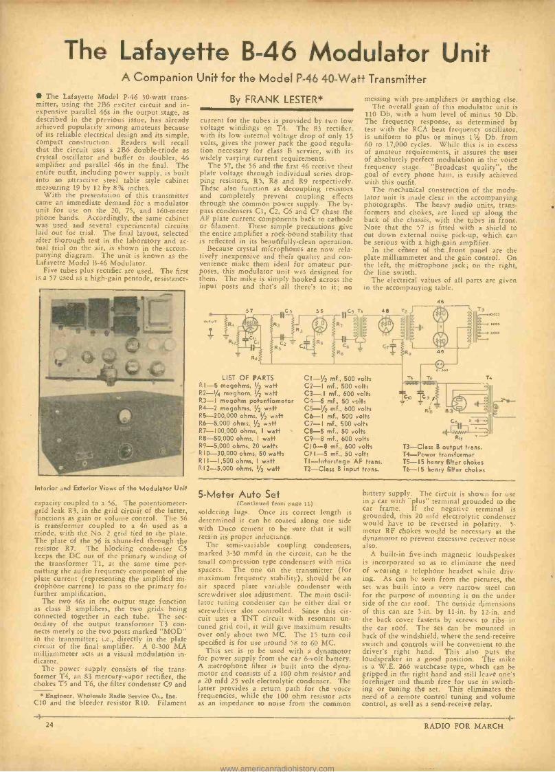
The Lafayette B -46 Modulator Unit A Companion Unit for the Model P -46 40 -Watt Transmitter
The Lafayette Model P -46 30 -watt trans- mitter, using the 2B6 exciter circuit and in- expensive parallel 46s in the output stage, as described in the previous issue, has already achieved popularity among amateurs because of its reliable electrical design and its simple, compact construction. Readers will recall that the circuit uses a 2B6 double -triode as crystal oscillator and buffer or doubler, 46 amplifier and parallel 46s in the final. The entire outfit, including power supply, is built into an attractive steel table style cabinet measuring 19 by 12 by 8% inches.
With the presentation of this transmitter came an immediate demand for a modulator unit for use on the 20, 75, and 160 -meter phone bands. Accordingly, the same cabinet was used and several experimental circuits laid out for trial. The final layout, selected after thorough test in the laboratory and ac- tual trial on the air, is shown in the accom- panying diagram. The unit is known as the Lafayette Model B -46 Modulator.
Five tubes plus rectifier are used. The first is a 5 u,rd :tea high-gain pentode, resistance-
Interior and Exterior Views of the Modulator Unit
capacity coupled to a 56. The potentiometer - grid leak R3, in the grid circuit of the latter, functions as gain or volume control. The 56 is transformer coupled to a 46 used as a triode, with the No. 2 grid tied to the plate. The plate of the 56 is shunt -fed through the resistor R7. The blocking condenser C5 keeps the DC out of the primary winding of the transformer Ti, at the same time per- mitting the audio frequency component of the plate current (representing the amplified mi- crophone current) to pass to the primary for further amplification.
The two 46s in the output stage function as class B amplifiers, the two grids being connected together in each tube. The sec- ondary of the output transformer T3 con- nects merely to the two posts marked "MOD" in the transmitter; i.e., directly in the plate circuit of the final amplifier. A 0 -300 MA milliammeter acts as a visual modulation in- dicator.
The power supply consists of the trans- former T4, an 83 mercury -vapor rectifier, the chokes T5 and T6, the filter condenser C9 and
Engineer, Wholesale Radio Service Co.. Inc. C10 and the bleeder resistor RI0. Filament
-k
By FRANK LESTER*
current for the tubes is provided by two low voltage windings on T4. The 83 rectifier, with its low internal voltage drop of only 15 volts, gives the power pack the good regula- tion necessary for class B service, with its widely varying current requirements.
The 57, the 56 and the first 46 receive their plate voltage through individual series drop- ping resistors, R5, R8 and R9 respectively. These also function as decoupling resistors and completely prevent coupling effects through the common power supply. The by- pass condensers C1, C2, C6 and C7 chase the AF plate current components back to cathode or filament. These simple precautions give the entire amplifier a rock -bound stability that is reflected in its beautifully -clean operation.
Because crystal microphones are now rela- tively inexpensive and their quality and con- venience make them ideal for amateur pur- poses, this modulator unit was designed for them. The mike is simply hooked across the input posts and that's all there's to it; no
57
messing with pre -amplifiers or anything else. The overall gain of this modulator unit is
I10 Db, with a hum level of minus 50 Db. The frequency response, as determined by test with the RCA beat frequency oscillator, is uniform to plus or minus 1t /z Db. from 60 to 17,000 cycles. While this is in excess of amateur requirements, it assures the user of absolutely perfect modulation in the voice frequency stage. "Broadcast quality ", the goal of every phone ham, is easily achieved with this outfit.
The mechanical construction of the modu- lator unit is made clear in the accompanying photographs. The heavy audio units, trans- formers and chokes, are lined up along the back of the chassis, with the tubes in front. Note that the 57 is fitted with a shield to cut down external noise pick -up, which can be serious with a high -gain amplifier.
In the center of the front panel are the plate milliammeter and the gain control. On the left, the microphone jack; on the right, the line switch.
The electrical values of all parts are given in the accompanying table.
46
LIST OF PARTS RI -5 megohms, 1/2 watt R2 -1/4 meghom, i/Z watt R3 -I megohm potentiometer R4-2 megohms, 1/2 watt R5- 200,000 ohms, 1/2 watt R6 -5.000 ohms, 1/2 watt R7- 100,000 ohms, I watt R8- 50,000 ohms, I watt R9 -5,000 ohms, 20 watts RIO-30,000 ohms, 50 watts RI I -1,500 ohms, I watt R12-5,000 ohms, I/2 watt
CI -1/2 mf., 500 volts C2 -I mf., 500 volts C3 -.I mf., 600 volts C4-5 mf., 50 volts C5 -I/2 mf., 600 volts C6-I mf., 500 volts C7 -I mf., 500 volts C8 -5 mf., 50 volts C9 -8 mf., 600 volts C10-8 mf., 600 volts CI I -5 mf., 50 volts TI- Interstage AF trans. T2 -Class B input trans.
R,r
T3 -Class B output trans. T4 -Power transformer 75 -15 henry filter chokes T6-I5 henry filter chokes
5 -Meter Auto Set (Continued from page 11)
soldering lugs. Once its correct length is determined it can be coated along one side with Duco cement to be sure that it will retain its proper inductance.
The semi -variable coupling condensers, marked 3 -30 mmfd in the circuit, can be the small compression type condensers with mica spacers. The one on the transmitter (for maximum frequency stability), should be an air spaced plate variable condenser with screwdriver slot adjustment. The main oscil- lator tuning condenser can be either dial or screwdriver slot controlled. Since this cir- cuit uses a TNT circuit with resonant un- tuned grid coil, it will give maximum results over only about two MC. The 15 turn coil specified is for use around 58 to 60 MC.
This set is to be used with a dynamotor for power supply from the car 6 -volt battery. A microphone filter is built into the dyna- motor and consists of a 100 ohm resistor and a 20 mfd 25 volt electrolytic condenser. The latter provides a return path for the voice frequencies, while the 100 ohm resistor acts as an impedance to noise from the common
battery supply. The circuit is shown for use in s car with "plus" terminal grounded to the car frame. If the negative terminal is grounded, this 20 mfd electrolytic condenser would have to be reversed in polarity. 5- meter RF chokes would be necessary at the dynamotor to prevent excessive receiver noise also.
A built -in five -inch magnetic loudspeaker is incorporated so as to eliminate the need of wearing a telephone headset while driv- ing. As can be seen from the pictures, the set was built into a very narrow steel can for the purpose of mounting it on the under side of the car roof. The outside dimensions of this can are 3 -in. by 11 -in. by 12 -in. and the back cover fastens by screws to ribs in the car roof. The set can he mounted in back of the windshield, where the send -receive switch and controls will be convenient to the driver's right hand. This also puts the loudspeaker in a good position. The mike is a W.E. 266 watchcase type, which can be gripped in the right hand and still leave one's forefinger and thumb free for use in switch- ing or tuning the set. This eliminates the need of a remote control tuning and volume control, as well as a send -receive relay.
24 RADIO FOR MARCH 4-
www.americanradiohistory.com
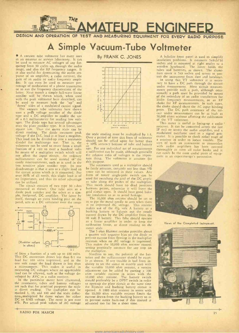
AMATEUR ENGINEEP DESIGN AND OPERATION OF TEST AND MEASURING EQUIPMENT FOR EVERY RADIO PURPOSE
A Simple Vacuum -Tube Voltmeter A vacuum tube voltmeter has many uses
in an amateur or service laboratory. It can be used to measure AC voltages of any fre- quency from 30 cycles up, through the audio range, and also the RF frequency ranges. It is also useful for determining the audio res- ponse of an amplifier, a radio receiver, the gain of an audio or radio frequency ampli- fier. It can even be used to measure per- centage of modulation of a phone transmitter or to run the frequency characteristic of the latter. Next month a simple full -wave linear rectifier will be shown which, when used with the peak voltmeter here described, can be used to measure both the "up" and "down" sides of a modulated carrier signal.
The vacuum tube voltmeter here shown uses a peak voltage rectifier of the diode type and a DC amplifier to enable the use of a 0 -1 milliammeter for reading low volt- ages. The diode type has several advantages over the plate rectifier type. It is linear, not square law. Thus the meter scale can be direct reading. The diode measures peak voltage if the D.C. load is at least a megohm. This load can be divided -up into a resistance divider for multirange use. That is, the voltmeter can be used to cover from a small fraction of a volt to over a hundred volts by means of a multiplier switch which will not affect the input circuit. An ordinary milliammeter can be used instead of ' the costly miscroammeter, such as is used in the less sensitive plate rectifier type. Its one disadvantage is that it acts as a slight load on the circuit across which it is connected. For over 90% of all needs, this slight load is of no importance, and thus its other advantage can be utilized.
The circuit consists of two type 30 tubes connected as shown. One tube acts as a diode peak rectifier and the other as a sim- ple, foolproof, DC amplifier. The latter by itself, through an extra binding post on the panel, acts as a DC voltmeter over the range
11 G 000UG v.tiw
NCc
GQUGG ` 0.
30 30
(Resistor values in ohms)
-..... ON-01,
I UUG
G- -1IIIIIIII . G v
of from a fraction of a volt up to 100 volts. This DC connection draws less than 0.1 ma load for 100 volts impressed, and in the one volt range the load drawn is less than a microampere. This makes it useful in measuring DC voltages where no appreciable load can be allowed, such as the voltage de- veloped by AVC in a radio receiver.
In the particular meter here illustrated, the resistances, tubes and battery voltages are such that for practical purposes the scale is direct reading. The multiplier can be marked 1, 10, and 100 and the scale deflec- tion1multiplied by those values for either DC or RMS voltage. The error is not over 6 %. For actual peak values of AC voltage
By FRANK C. JONES
,..
r .)
.G
°s.v ,
< d e
o > ,..
,
G .4 .3 .3 .3 A .7 . .f , C
(MC .c u01.)
the scale reading must be multiplied by 1.4. Over a period of time this form of voltmeter should not be relied upon for better than + 10% accuracy because of tube and battery age. For any individual set of measurements a calibration can be made, although generally the relative ratio of voltages is the impor- tant thing. The voltmeter is accurate for this purpose.
The resistances used as a multiplier should be fairly accurate, certainly not less than 5% error can be tolerated in their values. Any form of rotary single -pole switch can be used for switching the grid of the DC ampli- er tube along the points of the multiplier. This swich should have no dead positions between points, otherwise it will leave the grid circuit open. It should have good bake- lite insulation so as to avoid leakage.
The 10,000 ohm resistor should be set so as to put the metal needle to zero when there is no impressed AC voltage. This resistor makes use of the 41/2 volt A battery as a bucking battery to balance out the steady current drawn by the DC amplifier from the 90 volt B battery. This tube should operate as a linear amplifier in order to keep the calibration linear, or direct reading on the meter scale.
The 5 ohm filament resistor provides about a quarter volt negative bias on the diode to prevent current from flowing in the multiplier resistors when no AC voltage is impressed. This makes the 10,000 ohm resistor control setting practically constant for any step on the multiplier.
Needless to say, the polarity of the bat- teries and the milliammeter should he exact- ly as shown. If any trouble is had from in- ability to set the meter to exactly zero with the variable 10,000 ohm resistor, a vernier adjustment can be added by putting a 200 ohm variable resistor in series with the 10,000 ohm resistor. The battery switch should preferably be a DPST switch in order to open -up the plate circuit at the same time the filament and bucking battery circuit is opened. A 1000 ohm resistor in series with the 10,000 ohm variable resistor limits the current drawn from the bucking battery so as to prevent meter burn -out if this control is advanced too far for a short time.
A bakelite front panel is used to simplify insulation problems. It measures 5x8x3/16 inches and is mounted at right angles to a wooden baseboard. The latter holds the tubes and batteries, as shown. The alumi- num cover is 5x9 inches and serves to pro- tect the instrument from dust and breakage.
In using this VT voltmeter it is neces- sary to have a DC path through the circuit under measurement. Most circuit measure- ments provide such a path, although occa- sionally a path must be provided by means of the secondary of an audio transformer for audio frequency measurements, or an RF choke for RF measurements. In such cases, the choke should shunt the AC input binding posts. The DC path resistance of the cir- cuit under measurement can be as high as 50,000 ohms without affecting the calibration of the VT voltmeter.
This meter is useful in lining -up a radio receiver. It can be connected across the last IF coil or across the audio amplifier, and a modulated oscillator used as a signal gen- erator. It is possible to check either stage of a receiver in order to locate trouble. The uses of such an instrument in connection with audio amplifiers has been covered thoroughly in most all radio books and it can easily be the most useful piece of equip- ment in an experimenter's possession.
Views of the Completed Instrument.
RADIO FOR MARCH
www.americanradiohistory.com
:esaprRIssm:.e ,,..-e ..y.,s u.-. j.
HEADQUARTER)
SEND FOR THIS CATALOG! IT LISTS EVERYTHING FOR SHORTWAVE
TRANSMITTING AND RECEIVING Aerials Chokes Coils and Forms
Condensers Crystals and
Holders Dials and Knobs Insulators Jacks. Pluns Keys - Meters Monitors
Oscilloscopes Power Packs Preselectors Relays Receivers Resistors Sockets Transformers Transceivers Tubes - Tubing Wave Meter
NOW IN STOCK THE NEW RCA -ACR 136
COMMUNICATIONS RECEIVER
Write for Literature
SEND FOR THE ALLIED CATALOG
Allied Radio ALLIED RADIO CORPORATION 833 W. Jackson Blvd., Chicago, Dept. J.
Send me your FREE 1935 Catalog.
Send me the RCA -ACR 136 Bulletin.
Name
Address
City ......... i
7 -P01 NT MI FELL 20 FEET
STILL GOOD AS EVER rI
. . . AND STILL NO FEEDBACK!
Johnston P. A. Service, Oneonta. N.Y., writes us: We are certainly well
pleased with your velocity mike (the
7 -point Mike). 1Ve believe that ne
other mike can take the punishment it has and still work. One time it fell 20 feet to the grm od. And dozens of
times it has seen rain. We use it it MN mobile outfit, and its just as good
as ever. Also a wonderful help in eli- minating acoustical feedback." Guar-
anteed. Order from your wholesaler, of
write for illustrated Bulletin R2.
Aiwv[Rrrc (yrsor.rtan ADV. NEW +Oe
jO IN 10 WEEKS BY SHOP WORK -NOT BY BOOKS
I'll FinanceYour Training! -
Prepare for jobs In Service Work, Isroad- :,=tins:.Talking Pictures, Teluvi,ion, \Clrrlcsn.
ate , by 10 weeks practical shop work in Coyne Shop, l'mc Employment Seraleo. Many earn while
letrnioe Write tar BIG FREE RADIO and TELEVISION DOOR, and detalls.4 niy Pay- After -Graduation "Plan. H. C. LEWIS, President, Cn.. r, R hDIO
COO 500 S. Paulina St. (Dept. 35 -3M.
$ 1 brings you the next four issues of "RADIO''- Subscribe NOW.
} 26
Osockme, Japan. January 23, 1935.
Editor of Free Prize DFpartment of "RADIO ", Dear Ed
This are hamfest seasons of year, and Scratchi find numerous and many invitations in male box for requests of presence at attendance at such Cost for tickets very from two $ and reverse. Such hamfest each try to undo and outdo one and each other until time soon come when radio manu- torturers will be asked to donate entire year pro- duction of parts to give away in form of free prizes. One manufacturer have writ me private personal letters some weeks hence in which he ask for my humbling opinion as to solution of prob- lem. I make answer to him far better to go into automobile manufacturing business because people who go to automobile meetings are not given free cars as prizes every time crowd get together for hamfest and drinks.
It are beyond reason of Scratchi brain scope to see into dense scheme where radio manufacturers are required to give next year's dividends in form of radio parts to each of several hundred ham - fi sts which are held about in all cities so oftrn that special calenders are soon make publish to show with red circles each day of month on which some hamfest are not held somewhere someplace, at some time or in future.
Scratchi have make round about tour of radio shops to solicit prizes from store owners. I were make chairman goat for big hamfest here in Osock- me. First dealer I go to tell me he cannot give me free prize because he are superstitious people and are afraid that prize winner will come back to his store and try to sell prize back to him for more than dealer paid for it.
Next dealer I go to call me all kinds of names which I read once in my Bible. but which do not sound so good when come from husky lungs of angry dealer. Another dealer are more good friendly person. He take me into private office and ask me what I want. I give him long list of special prizes of great value and he tell me he will take matter up and under consideration. So he open up bottle of juice of the grape and we drink from such. We then drain contents from bottle of rare old Scotch, which his brother -in -law make in spare time at home. Next we make drink from long neck, false bottom bottles of eight atar McElroy and soon we begin feel pretty friendly. Dealer then bring out inventory sheets and show me how great are his business for month just past. Column on right of ledger show that eleven hundred dollars are taken in for sale of parts to radio hams, and column on left show that he give away twelve hundred dollars for hamfest prizes. So he ask me what are secrets of success in radio store business when it cost one hundred dollars more for prizes for hamfests than he take in in cash. To wich I reply with toothsome smile, such question are riddle for income tack collector to solve.
11t-think he are trying to give me bum's rush, so I ask him again for free prizes. He answer by opening up another bottle of spirits of corn. We drink from such. Scratchi are not drinking man. He have never have more than two drinks ut one time together. He pour another. Scratchi make protest. But he hold beautiful $300 crystal microphone near my face and shake it in front of me. Such are great temptation. so Scratchi take another drink. He then produce huge carton of assorted high power tubes and shake them up in front of me. Scratchi take another drink. He next bring out magnificent assortment of AT -cut quartz crystals. Such are Scratchi's weakness. So Scratchi take another drink.
Harnfest are going to be huge and glorious suc- cess, methinks why not? So he pour contents of one more bottle into me. He tell me he will soon call express wagon to take hamfest prizes and me home together. By time that express wagon ar- rive. Scratchi are half way on road to Limbo. I are so full of happiness I bubble inside and outside. Dealer friend give rapid instructions to store clerk to carefully wrap up large assortment of prizes for Scratchi to take homeward. While clerk are wrapping such prizes, Scratchi hear sounds that are like glass clicking together. Ah, think I, such are assortment of large power tubes which dealer will donate. So Scratchi take another drink. Suc- cess are closer at hand.
Dealer friend walk in with huge package under his arm and hand to express -man. Scratchi are overcome with great happiness and chuckle forth
(Continued on page 28)
Lady -Call Constable Centralab !
. he'll soon put a stop to that noisy "picket fence" attenuation. If your radio acts up, Madam, call a good serviceman ... he'll change that noisy wire -wound control to a smooth as silk CENTRALAB Radiohm that will forever ban ish "picket fence" reception. Note to servicemen: A mere handful of CEN. TRALAB RADIOHMS will service practically any radio that is still worth fixing. Employs the smooth, non -rubbing contact in both high and low resistance values. Furnished with fixed mini- mum external resistor at no extra cost.
Radiohms Resistors Suppressors
Sound Projection Controls
(Division of) GLOBE UNION MFG. CO.
MILWAUKEE
At Last! - - - NAME PLATES
CLASS A MODULATOR
YOU have always wanted transmitter and aasD-
ciate equipment name plates -now you can have them -and at a really low price, too. In the list you will find plates covering every conceivable require- ment.
Specifications: Made of brass with charac- ters and border chromium plated. satin fin- ish. Background etched black. Size: 2%x% inches. Corners rounded. Furnished com- plete with self -tapping machine screws for mounting on metal, hakelite. or wood.
LIST OF NAME PLATES AVAILALBLE Oscillator 3rd Buf. -Dblr. Plate Microphone
Crystal Ost. Plate 3rd Buf. -Dblr. Grid Gain Control
Crystal Osc. Grid Power Amp. Plate c' Modulation
Tritet Ow. Power Amp. Grid 200 Ohm Input Tripler Plate Antenna 200 Ohm Output Tripler Grid Neut. Condenser 500 Ohm Input Transmitter Plate Voltage 500 Ohm Output
1st Buffer Grid Filament Voltage 50 Ohm Input 2nd Buffer Grid Key 50 Ohm Output
3rd Buffer Grid Rectifier 125 Ohm Input 1st Buffer Plate AC Inrut 125 Ohm Output 2nd Buffer Plate Modulator Plate Input 3rd Buffer Plate Modulator Grid Output 1st But-Dblr. Plate Class B Modulator Transceiver 1st But-D°lr. Grid Class A Modulator Monitor 2nd Buf.Dhlr.Plate Sp. Amp. Dvr. Plate Send 2nd Buf. -Dblr. Grid Receive
NET PRICE, EACH, COMPLETE WITH plus postage MOUNTING SCREWS
At your favorite jobbing supply house. Illustrated circular upon request.
GORDON SPECIALTIES COMPANY 2.33 EAST AVENUE PARK RIDGE, ILLINOIS
IOc
RADIO FOR MARCH
www.americanradiohistory.com
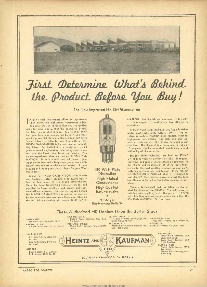
3LL O fjunthQ (OJwd!i &/thwl Amittri &4oì& 2,o y!
The New Improved HK 354 Gammatron
TAKE no risk! You cannot afford to experiment whon purchasing high -power transmitting tubes. You must know in advance that you are getting
value for your money, that the guarantee behind the tube means what it says. You want to know
that your tube was engineered by men who have
spent a proverbial lifetime in the design of just ONE line of tubes ... tubes for your transmitters. The
HK -354 GAMMATRON is the ace among transmit- ting tubes. For behind it is a pedigree . . . 20
years of sound engineering, painstaking care to see
that only the finest tubes leave the factory. You
do not experiment when you buy an HK -354 GAM - MATRON. Here is a tube that will convert your input power into radio frequency power more effi- ciently than any other tube on the market. A tube capably of handling one kilowatt input for your C.W. transmitter.
B3hind this HK -354 GAMMATRON is the Heintz and Kaufman factory, utilizing over 40,000 square
feet of floor area. It is a sound establishment. Here the finest transmitting tubes are made, and
supplied to large maritime and commercial com-
munication companies. The engineering skill behind
the HK -354 GAMMATRON is proved in practice by the hundreds who now have these new tubes on
the air. Ask any amateur who uses a HK -354 GAM-
I50 Watt Plate Dissipation
High Mutual Conductance High Out -Put Easy to Excite
Write for Engineering Bulletin
MATRON. Let him tell you how easy it is to excite . . . how rugged its construction, how efficient its
operation.
In the HK -354 GAMMATRON you find a Tantalum plate, most costly plate material known. The en- velope is made of NONEX glass, hardest, finest for high -power tube design. The plate and grid sup- ports are original, as is the massive base and socket structure. The filament is a husky one, 5 volts at
10 amperes, rigidly supported maintaining a high uniformity of characteristics.
HK -354 GAMMATRONS are built to STAND UP. It took years to perfect this tub.. It requires expensive and special manufacturing equipment. In
the Heintz and Kaufman plant where these tubes are made, the most exacting engineering and manu- facturing methods are maintained. Every HK -354 GAMMATRON is PERFECT when it is shipped to your dealer. The immediate success which this tub has attained is the talk of the better amateurs very- where.
Want a testimonial? Ask the fellow on the air what he thinks of the HK -354. You will never be satisfied with anything less. The price . . . $24.50 net. Leading amateur supply houses stock the HK- 354 GAMMATRON. Go see them!
These Authorized HK Dealers Have the 354 in Stock
BOSTON, MASS. The Radio Shack, 46 Brattle Street
CHICAGO, ILLINOIS Mid -West Radio Mart, 520 So. State St.
SAN FRANCISCO
I. S. Cohen's Sons, 1025 Mar- ket Street
Zack Radio Supply, 1470 Mar- ket Street
OAKLAND Electric Supply, 51 - 12th St. E. C. Wenger, 1020 Oak St.
0
SPOKANE, WASH. S.-ska e Radio Company, Inc., 611 1st Avenue
ST. PAUL, MINN. Lew Bonn Company, 2484 -2486 Uni- versity Avenue, Midway
PORTLAND. OREGON NEW YORK, N. Y.
Stubs Electric Company, Park and Couch Wholesale Radio Service Company, Inc.. Streets 100 - 6th Avenue
YOU NGSTOWN. OHIO Ross Radio Company, 46 E. Federal St.
NEWARK, N. J. Kalter & Romander. 62 Court Street
EINTZ AND KAUFMAN a LTD
SOUTH SAN FRANCISCO, CALIFORNIA
LOS ANGELES Pacific Radio Exchange, 729 South Mail Street Radio Simply Company, 912 South Broadway
SEATTLE, WASH. Seattle Radio Supply. 2319 2nd Avenue Northern Radio Company, Joseph Vance Bldg.
RADIO FOR MARCH
www.americanradiohistory.com
Shhh! Shhh7 DIET
/ndividua //y TESTED for NOISE
Of course, you've heard OF it -but you've never HEARD it!
The New
ELECTRAD VOLUME CONTROL
Is
GUARANTEED
QUIET
WERE is the great achievement of modern radio engineering -a vol-
ume control, so radically improved in design and smooth in operation, it is guaranteed quirt The resistance clement is baked on the flat outer rim of a rigid Bakelite ring. Over this, the special -alloy floating con- tact gently glides in a straight path. More even distribution of current and longer life are attained. Molded Bake- lite case, when mounted, projects only one -half inch back -panel. New type power- switch (approved by underwrit- er's) instantly attached or detached. Long, easy -to -cut, aluminum shaft. All standard values.
EI.EÇTRAD
',N/Q°
Name
ttPAddross PR-3
-J i
ELECTRAD, Inc.
175 Varick St., New York, N. Y.
Please send new 1935 Resistor Catalog . Cheik here for (older on now QI'IET Volume Control.
CANNON -BALL HEADSETS Made by America's oldest manufacturer of headsets
Heavy bar magnets, double pole, aluminum cases, D. C. resistances of 2000, 3000 and 5000 ohms. Sturdy construction, sensitive and faithful in reproduction.
Sold everywhere in America
C. F. CANNON CO. SPRINGWATER, N. Y.
28
SCRATCH I (Continued from page 26)
and fifth with delirious words of kindness and thanks for dealer friend. So he give me another drink.
And when I wake up in my home several days thereafter and look around me, I make wonder where I have been in my past absence. I recall I have make visit to dealer store for hamfest prizes. Lo and be hold and be dropped, I see in corner of room huge package which dealer friend hand to express man when he take me and hamfest prizes home in company together. He are my pal, he are my pal, I shout with glee. He fill me full of liquor spirits, he send me home in express wagon, and he send along great package of ham - fer:t prizes.
I quickly open large bundle to see what make and type of power tubes he give for prize. What do I find? Fourteen empty liquor bottles and a bill for $12 for liquor I consume in his store.
I make rapid foot to dealer store and demand explanation for such joke. Dealer friend say it are no joke and he inform me that he have long since gone out of radio business because he were forced to give away more prizes for hamfests than merchandise he sell in each year. He say he keep radio store sign on front door only as lifetime re- minder to him to show him how much more profits there are in liquor business than in running radio store.
As I make say more previously, Hon. Ed., he are my pal, he are my pal. Hoping you will always be the same. I am.
Your Hamfest Prize Promotor, Hashafisti Scratchi.
The Single Tube 35 -I9 Transceiver
(Continued from page 11)
monitor the speech. This circuit is so sim- ple that two sets can easily be built for duplex operation, using one as a receiver and the other only as a transmitter. A 6.3 volt pilot lamp is a useful tool for testing this set. A single turn of wire about an inch in diameter enables this lamp to be coupled to the oscillator coil. It should light up when testing the transmitter; when the mike is spoken into loudly, the lamp should be- come somewhat dimmer. Too -loose coupling will give no modulation and too high coup- ling will cause the transmitter to stop oscil- rating due to excessive absorption modula- tion. A low resistance single button micro- phone should be used. - -...
FORMS' CLOPE RATEP 10tPER ON THE IOth WORD PAYABLE OF MONT N IN ADVANCE
CLA 111:2411D. DAlikD.Ar
QSLs, 75c per 100. 2 colors. W9DGH, 1816 5th Ave. North, Minneapolis, Minnesota.
MODULATED OSCILLATORS. Built to specifica- tions of A. Binneweg, Jr., as described in this issue. Mounted in neat metal case. Vernier Dial. Calibrated for the 15 to 200 meter range. Two- volt DC Model, complete with three calibrated coils and the two tubes, $13.00 net. AC Model, less power pack, $16.00 net, complete with calibrated coils and the two tubes. Calibrated AC Model with built -in power, for 110 -volt AC operation, $20.00 net, complete with calibrated coils and the two necessary tubes. DELFT RADIO MFG. CO., 624 Fairbanks Ave., Oakland. California.
RADIO ENGINEERING RCA Institutes offers an Intensive course of high standard embracing all phases of Radio. Practical train- ing with modern equipment at New York and Chicago schools. Also spe- cialized courses and Home Study Courses under "No obligation" plan. Illustrated catalog on request.
RCA INSTITUTES, INC., Dept. RA -34 75 Varick St., N. Y. 1154 Merchandise Mart, Chicago
Recognized Standard in Radio Instruction Since 1909
MICA CONDENSERS
... AEROVOX Engineered
There's ample reason why Aerovox Types 1455,
1456 and 1457 Mica Transmitting Condensers
depart from conventional design. For instance:
Flat ton and bottom permit rerfect stacking for
compact assemblies or condenser banks.
Insulated mounting hales permit any mounting inde-
pendent of electrical connections.
Insulated terminals permit any combination or in-
dividual wiring. series or parallel connections.
Special terminals permit soldered connections with-
out harmful heat transfer to encased section.
1000, 2500 and 5000 Volt D.C. ratings. Wide
range of capacities. Values stamped on each unit.
Aerovox engineering spells qualir). Aerovox mass production
spells Ion. price. Remember, Aerovox list prices are equal and
in many instances lower than competitive makes. Why pay more
and get less?
FREE DATA: New 1935 Catalog is yours for the asking.
Also sample copy of Research Worker. Look for yellow and
black carton when buying sondensers or resistors.
84 Washington St.
CORPORATION
:: Brooklyn, N. Y.
LEARN CODE QUICKLY AND EASILY AT HUM[.
THE INSTRUCTOGRAPH
Enables You to Practice ANY TIME - ANY WHERE
ANY SPEED The m: a practicable meth -
.d of le:inúng the cede on the market today. Leading schools and the (eiernment use tape marline: because there 1a
nothing tint ir. START NOW with the ofd
of an INSTRt'CTl1CIlAPII TO QI'I('K1.Y MASTER THE COPE and send int,Iligently with the best of them.
For sale (cash or tens) or for rent at a reasonable price. Rental can be applied on purchase price. One additional month free if rented for 2 months. A post card will bring full particulars.
INSTRUCTOGRAPH CO. 915 LAKESIDE PLACE, DEPT. S.F. 3 CHICAGO Representative for Candela: Radio College of Canada,
863 Bay Street, Toronto, Ont.
RADIO FOR MARCH
www.americanradiohistory.com
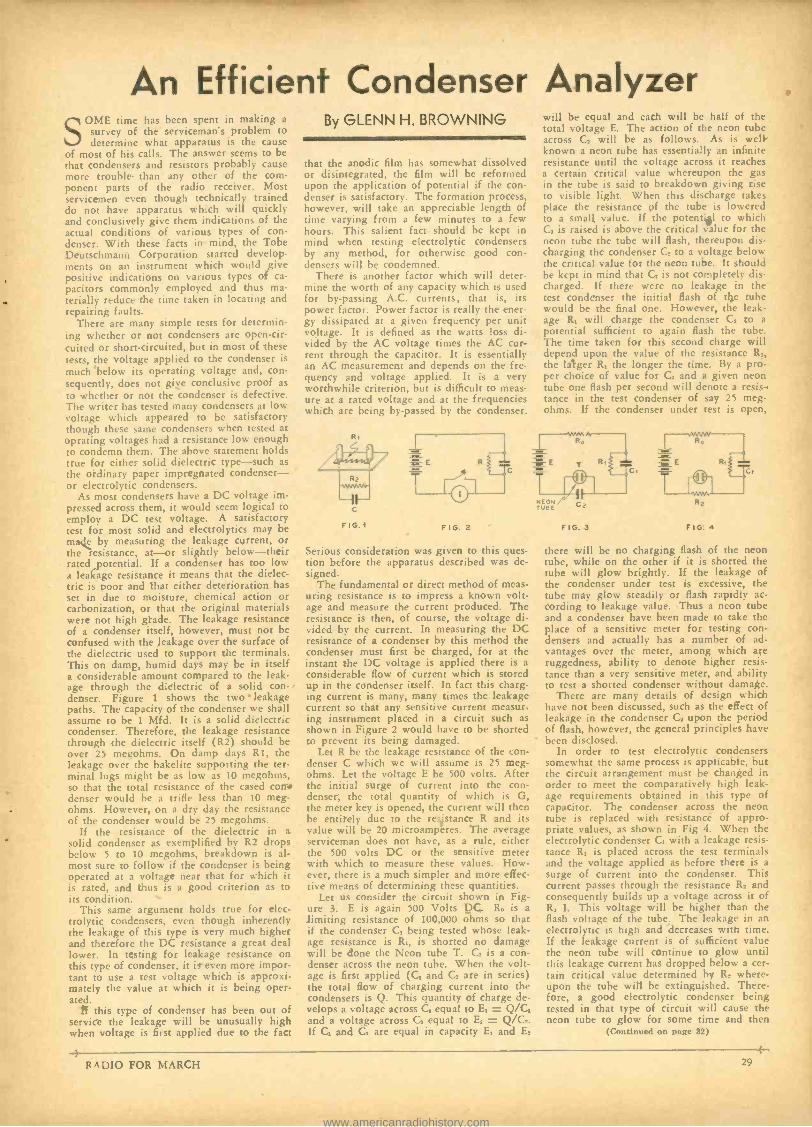
An Efficient Condenser Analyzer SOME time has been spent in making a
survey of the serviceman's problem to determine what apparatus is the cause
of most of his calls. The answer seems to be that condensers and resistors probably cause more trouble than any other of the com- ponent parts of the radio receiver. Most servicemen even though technically trained do not have apparatus which will quickly and conclusively give them indications of the actual conditions of various types of con- denser. With these facts in mind, the Tobe Deutschmann Corporation started develop- ments on an instrument which would give positive indications on various types of ca- pacitors commonly employed and thus ma- terially reduce the time taken in locating and repairing faults.
There are many simple tests for determin- ing whether or not condensers are open -cir- cuited or short- circuited, but in most of these tests, the voltage applied to the condenser is
much below its operating voltage and, con- sequently, does not give conclusive proof as to whether or not the condenser is defective. The writer has tested many condensers at low voltage which appeared to be satisfactory though these same condensers when tested at oprating voltages had a resistance low enough to condemn them. The above statement holds true for either solid dielectric type -such as the ordinary paper impregnated condenser - or electrolytic condensers.
As most condensers have a DC voltage im- pressed across them, it would seem logical to employ a DC test voltage. A satisfactory test for most solid and electrolytics may be made by measuring the leakage current, or the resistance, at-or slightly below -their rated potential. If a condenser has too low a leakage resistance it means that the dielec- tric is poor and that either deterioration has set in due to moisture, chemical action or carbonization, or that the original materials were not high grade. The leakage resistance of a condenser itself, however, must not be confused with the leakage over the surface of the dielectric used to support the terminals. This on damp, humid days may be in itself a considerable amount compared to the leak- age through the dielectric of a solid con denser. Figure 1 shows the two' leakage paths. The capacity of the condenser we shall assume to be 1 Mfd. It is a solid dielectric condenser. Therefore, the leakage resistance through the dielectric itself (R2) should be over 25 megohms. On damp days R1, the leakage over the hakelite supporting the ter- minal lugs might be as low as 10 megohms, so that the total resistance of the cased con+ denser would be a trifle less than 10 meg- ohms. However, on a dry day the resistance of the condenser would be 25 megohms.
If the resistance of the dielectric in a solid condenser as exemplified by R2 drops below 5 to 10 megohms, breakdown is al- most sure to follow if the condenser is being operated at a voltage near that for which it is rated, and thus is a good criterion as to its condition.
This same argument holds true for elec- trolytic condensers, even though inherently the leakage of this type is very much higher and therefore the DC resistance a great deal lower. In testing for leakage resistance on this type of condenser, it is even more impor- tant to use a test voltage which is approxi- mately the value at which it is being oper- ated.
If this type of condenser has been out of service the leakage will be unusually high when voltage is first applied due to the fact
By GLENN H. BROWNING
that the anodic film has somewhat dissolved or disintegrated, the film will be reformed upon the application of potential if the con- denser is satisfactory. The formation process, however, will take an appreciable length of time varying from a few minutes to a few hours. This salient fact should be kept in mind when testing electrolytic condensers by any method, for otherwise good con- densers will be condemned.
There is another factor which will deter- mine the worth of any capacity which is used for by- passing A.C. currents; that is, its power factor. Power factor is really the ener- gy dissipated at a given frequency per unit voltage. It is defined as the watts loss di- vided by the AC voltage times the AC cur- rent through the capacitor. It is essentially an AC measurement and depends on the fre- quency and voltage applied. It is a very worthwhile criterion, but is difficult to meas- ure at a rated voltage and at the frequencies which are being by- passed by the condenser.
R,
c
FIG.1 FIG. 2
Serious consideration was given to this ques- tion before the apparatus described was de- signed.
The fundamental or direct method of meas- uring resistance is to impress a known volt- age and measure the current produced. The resistance is then, of course, the voltage di- vided by the current. In measuring the DC resistance of a condenser by this method the condenser must first be charged, for at the instant the DC voltage is applied there is a
considerable flow of current which is stored up in the condenser itself. In fact this charg- ing current is many, many times the leakage current so that any sensitive current measur- ing instrument placed in a circuit such as shown in Figure 2 would have to be shorted to prevent its being damaged.
Let R be the leakage resistance of the con- denser C which we will assume is 25 meg- ohms. Let the voltage E be 500 volts. After the initial surge of current into the con- denser, the total quantity of which is G, the meter key is opened, the current will then be entirely due to the resistance R and its value will be 20 microamperes. The average serviceman does not have, as a rule, either the 500 volts DC or the sensitive meter with which to measure these values. How- ever, there is a much simpler and more effec- tive means of determining these quantities.
Let us consider the circuit shown in Fig- ure 3. E is again 500 Volts DC. R, is a limiting resistance of 100,000 ohms so that if the condenser C, being tested whose leak- age resistance is R,, is shorted no damage will be done the Neon tube T. C. is a con- denser across the neon tube. When the volt- age is first applied (C, and C. are in series) the total flow of charging current into the condensers is Q. This quantity of charge de- velops a voltage across C, equal to E, -Q /C, and a voltage across C, equal to E, = Q/C2. If C. and C. are equal in capacity E. and E.
will be equal and each will be half of the total voltage E. The action of the neon tube across C. will be as follows. As is well known a neon tube has essentially an infinite resistance until the voltage across it reaches a certain critical value whereupon the gas in the tube is said to breakdown giving rise to visible light. When this discharge takes place the resistance pf the tube is lowered to a small value. If the potential to which C, is raised is above the critical value for the neon tube the tube will flash, thereupon dis- charging the condenser C. to a voltage below the critical value for the neon tube. It should be kept in mind that C, is not completely dis- charged. If there were no leakage in the test condenser the initial flash of the tube would be the final one. However, the leak- age R. will charge the condenser C. to a potential sufficient to again flash the tube. The time taken for this second charge will depend upon the value of the resistance R,, the lager R, the longer the time. By a pro- per choice of value for C. and a given neon tube one flash per second will denote a resis- tance in the test condenser of say 25 meg- ohms. If the condenser under test is open,
FIG. 3
R2
FIG. 4
there will be no charging flash of the neon tube, while on the other if it is shorted the tube will glow brightly. If the leakage of the condenser under test is excessive, the tube may glow steadily or flash rapidly ac- cording to leakage value. Thus a neon tube and a condenser have been made to take the place of a sensitive meter for testing con- densers and actually has a number of ad- vantages over the meter, among which are ruggedness, ability to denote higher resis- tance than a very sensitive meter, and ability to test a shorted condenser without damage.
There are many details of design which have not been discussed, such as the effect of leakage in the condenser C. upon the period of flash, however, the general principles have been disclosed.
In order to test electrolytic condensers somewhat the same process is applicable, but the circuit arrangement must be changed in order to meet the comparatively high leak- age requirements obtained in this type of capacitor. The condenser across the neon tube is replaced with resistance of appro- priate values, as shown in Fig 4. When the electrolytic condenser C, with a leakage resis- tance R, is placed across the test terminals and the voltage applied as before there is a
surge of current into the condenser. This current passes through the resistance R2 and consequently builds up a voltage across it of R, I. This voltage will be higher than the flash voltage of the tube. The leakage in an electrolytic is high and decreases with time. If the leakage current is of sufficient value the neon tube will continue to glow until this leakage current has dropped below a cer- tain critical value determined by R. where- upon the tube will be extinguished. There- fore, a good electrolytic condenser being tested in that type of circuit will cause the neon tube to glow for some time and then
(Continued on page 32)
R ADIO FOR MARCH 29
www.americanradiohistory.com
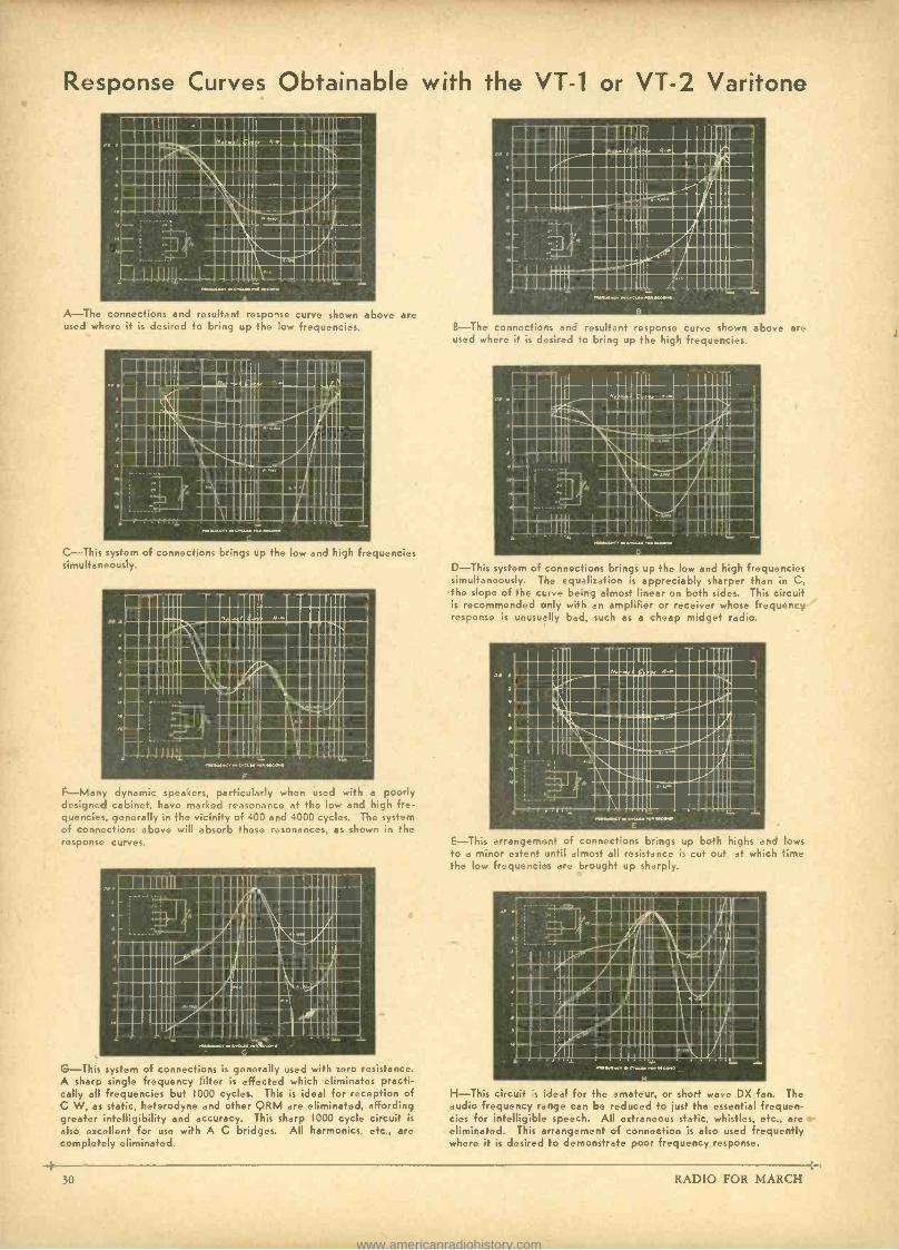
Response Curves Obtainable with the VT -1 or VT -2 Varitone
111111111111111111111111111111 111111111I1111!11111111111111111 IIitQ11111 1111I1118111M 111111111Nall11111 =MIMI= 1111111M\ \11111IIMII111111 11111IIM\11111 MINIMUM 111111111:l1 MINIM
11111 1111Ì 1111,1 1111 =MUM= 11111-Ei111111
111111 1111111111111111
A -The connections and resultant response curve shown above are used where it is desired to bring up the low frequencies.
111111 1111111111M1 III NIIIIIIIMIM111111/!111111i,1M 1111!im1111111 IÍi m II4J111111 !líil IllammuuIImmiICIII 111111\\111111111111111 MN 111111111\1111111111J11111 11111mus:!!III/Ìm1111
1\111111II®/1111 d11111Iep1111 II11 1nII11 INI IIIIn 11111111=111111111111M own.. v creum emcee*
C-This system of connections brings up the low and high frequencies simultaneously.
111111111111111111I IIIUI . 111111 111e11111111111111 1111!I:IIIIIIIIIIi: 1111111111111IIIIII
` 111111111131\11121111111M1 ; 111111 \11:í1111\1111''I
i1111I1\1111i11111 ÿ 111111'zsa11
1a 11111111©111111
11111ÌÌÌÌ 11.9111MPC, 1111 .C.PCLII ITN MOON.
F -Many dynamic speakers, particularly when used with a poorly designed cabinet, have marked reasonance at the low and high fre- quencies, generally in the vicinity of 400 and 4000 cycles. The system of connections above will absorb these resonances, as shown in the response curves.
1111m 111111 I i11mIm Ill I
Illl,llin1111lI /1111I111\i1111í1 1114111N\ C11i1111M
1111111.%11111111111111 11111IÌi111111111M1i11111,111 IIIIII11/i1111I=1\1115II1111 111111 /IiGIIII1::í1111 111111II11111111111111I 111111II/111111 C:111=I III!'i M11111I1e1111.1,
G -This system of connections is generally used with zero resistance. A sharp single frequency filter is effected which eliminates practi- cally all frequencies but 1000 cycles. This is ideal for reception of C W, as static, heterodyne and other QRM are eliminated, affording greater intelligibility and accuracy. This sharp 1000 cycle circuit is
also excellent for use with A C bridges. All harmonics etc., are completely eliminated.
-4 30
B -The connections and resultant response curve shown above are used where it is desired to bring up the high frequencies.
D -This system of :onnections brings up the low and high frequencies simultaneously. Tie equalization is appreciably sharper than in C, the slope of the ct.rve being almost linear on both sides. This circuit is recommended cnly with an amplifier or receiver whose frequency response is unusually bad, such as a cheap midget radio.
E -This arrangement of connectons brings up both highs and lows to a minor extent until almost all resistance is cut out, at which time the low frequencies are brought up sharply.
SI §1111111111111111M IN Ii,il1111,111M1
i/í/,111\M111,11 IN 5,111111\1i11111
91I/IIIINIM1101,,P11111 1 III/IIII11111L1I1/111 IIIII11111111\11d111M1 I1111í1I 111M11E/1111111 1:111 111111I=1111IIM 11111 %1111111=1I1111MMI ,IÍI H111111Ì111
MINININV C.1.1110 PM .0.0
H -This circuit s ideal for the amateur, or short wave DX fan. The audio frequency range can be reduced to just the essential frequen- cies for intelligible speech. All extraneous static, whistles, etc., are eliminated. This arrangement of connection is also used frequently where it is desired to demonstrate poor frequency response.
RADIO FOR MARCH
www.americanradiohistory.com
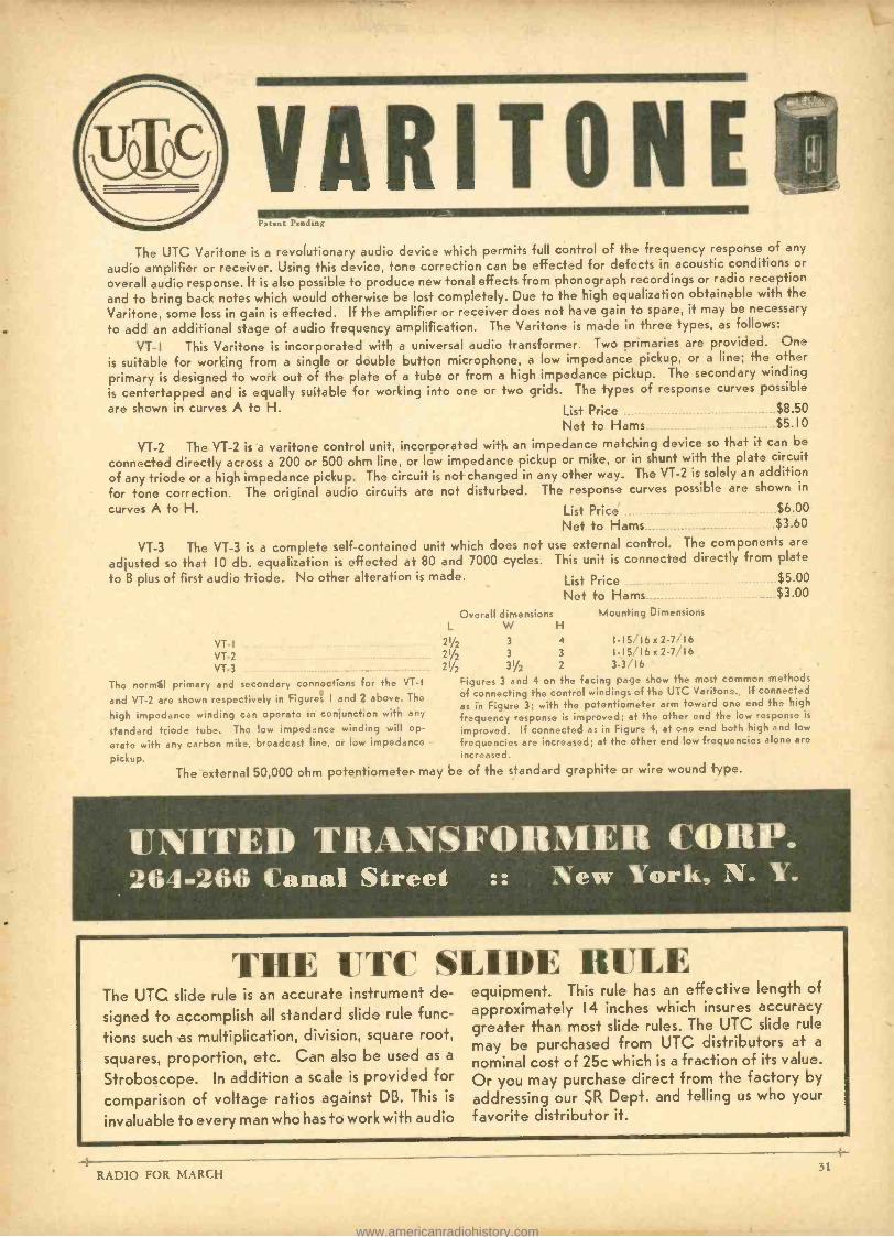
VARITONE 111111111. Patent Pending
The UTC Varitone is a revolutionary audio device which permits full control of the frequency response of any
audio amplifier or receiver. Using this device, tone correction can be effected for defects in acoustic conditions or
overall audio response. R is also possible to produce new tonal effects from phonograph recordings or radio reception
and to bring back notes which would otherwise be lost completely. Due to the high equalization obtainable with the
Varitone, some loss in gain is effected. If the amplifier or receiver does not have gain to spare, it may be necessary
to add an additional stage of audio frequency amplification. The Varitone is made in three types, as follows:
VT- I This Varitone is incorporated with a universal audio transformer. Two primaries are provided. One
is suitable for working from a single or double button microphone, a low impedance pickup, or a line; the other
primary is designed to work out of the plate of a tube or from a high impedance pickup. The secondary winding
is centertapped and is equally suitable for working into one or two grids. The types of response curves possible
are shown in curves A to H. List Price $8.50
Net to Hams $5.10
VT -2 The VT -2 is a varitone control unit, incorporated with an impedance matching device so that it can be
connected directly across a 200 or 500 ohm line, or low impedance pickup or mike, or in shunt with the plate circuit
of any triode or a high impedance pickup. The circuit is not changed in any other way. The VT -2 is solely an addition
for tone correction. The original audio circuits are not disturbed. The response curves possible are shown in
curves A to H. List Price $6.00
Net to Hams $3.60
VT -3 The VT -3 is a complete self- contained unit which does not use external control. The components are
adjusted so that 10 db. equalization is effected at 80 and 7000 cycles. This unit is connected directly from plate
to B plus of first audio triode. No other alteration is made.
VT- I
VT -2
VT -3
The normal primary and secondary connections for the VT -I
and VT -2 are shown respectively in Figures I and 2 above. The
high impedance winding can operate in conjunction with any
standard triode tube. The low impedance winding will op-
erate with any carbon mike, broadcast line, or low impedance
pickup.
List Price $5.00
Net to Hams $3.00
Overall dimensions Mounting Dimensions L W H
21/2 3 4 1 -15/16 x 2 -7 16
21/2 3 3 1-15/16 x 2-7,16
21/2 31/2 2 3 -3/ 16
The external 50,000 ohm potentiometer may
Figures 3 and 4 on the facing page show the most common methods
of connecting the control windings of the UTC Varitone. If connected as in Figure 3; with the potentiometer arm toward one end the high
frequency response is improved; at the other end the low response is
improved. If connected as in Figure 4, at one end both high and low
frequencies are increased; at the other end low frequencies alone are
increased.
be of the standard graphite or wire wound type.
UNITED TRANSFORMER CORP. 264 -266 Canal Street :: New York, N. Y.
THE UTC SLIDE RULE The UTC slide rule is an accurate instrument de-
signed to accomplish all standard slide rule func-
tions such as multiplication, division, square root,
squares, proportion, etc. Can also be used as a
Stroboscope. In addition a scale is provided for
comparison of voltage ratios against DB. This is
invaluable to every man who has to work with audio
equipment. This rule has an effective length of approximately 14 inches which insures accuracy greater than most slide rules. The UTC slide rule
may be purchased from UTC distributors at a
nominal cost of 25c which is a fraction of its value.
Or you may purchase direct from the factory by
addressing our SR Dept. and telling us who your favorite distributor it.
RADIO FOR MARCH
www.americanradiohistory.com

CROWE "MICROMASTER"
No. 192 MICRO - MASTER
(Illustration I/x laze)
Precision Recording Control For All Short Wave Sets
Has auxiliary pointer affording exact repeat indication of wave length. Sta- tions however closely crowded may be accurately logged.
Slow speed ratio 45 to I ; fast speed 9 to I in 360 degrees. Secondary pointer travels faster than double pointer.
Can be supplied with other scales or with special calibrations made to order. Specify scale wanted. Made in several sizes: 31/2 4 " and 23/4 " diameter of scale.
New escutcheons are featured for the various sizes and have a synthetic transparent non -inflammable Croglas convex crystal eliminating breakage. The crystal inserted in escutcheon seals air leakage or coupling behind baffle.
We carry in stock a complete line of name plates, dials, scales, etc., for transmitter panels. Send today for literature illustrating and describing our new material for Amateurs, Experimenters and Set Builders.
Export orders receive special attention, Cable Address -CROWNAME CHICAGO.
CROWE NAME PLATE & MFG. CO. 1755 GRACE STREET Established 35 Years CHICAGO, ILL., U. S. A.
Pacific Coast Representative -W. BERT KNIGHT, INC.
PERFECTION OF PERFORMANCE IS ATTAINED ONLY BY CAREFUL ATTEN- TION TO EACH MANUFACTURING DETAIL
THE electrodes used in Premier Crystal Holders are typical of our strict adherence to minute details. A crystal ground
flat and perfect in every other respect is worthless unless used between electrodes that STAY FLAT.
To make an electrode stay flat is not as easy as it sounds. Strains in the metal, possibly caused while the blanks are being stamped out, often produces distortions, the bad effects of which do not become evident for weeks or even months. Ultimately, the twisting of the plates, even though very slight, causes destruction of the crystal through arcing, re- duces the output, shifts frequency and sometimes destroys the crystal entirely by fracturing it. It took much longer to overcome these difficulties than it takes to tell about them. Brass would not behave and was discarded. We developed a nickel silver alloy which is specially heat treated to relieve the surface and aged by a unique process.
Determination of the correct thickness of the electrodes and the extraordinary pains taken to produce them, enable us to offer permanently flat and perfect electrodes. This important detail, in addition to many others, brings to the amateur, Crystals and Crystal Holders much nearer perfection than have ever before been produced.
Write for Bulletin 103 describing sixteen types of new Isolantite holders, "AT"-cut crystals, etc.
TYPE 180 ISOLANTITE
HOLDER
PREMIER CRYSTAL LABORATORIES, INC. 69 PARK ROW, NEW YORK, N. Y.
°°"`" LITTELFUSES A .. .,
Instrument Littlefuses. for meters. 1/200 amp. up. Hi. -Volt Littlefuses for transmitters, etc. 1000, 5000 aria 10,000 rot rawgrs, I'56 amp. up. Neon Voltage Fuses & Indicators (Tattelites) 100, 250, 500, 1,000 & 2,000 volt ratings. Aircraft Fuses Auto Fuses, Fuse Mountings, etc.
Get new Catalog No. 6 LITTLEFUSE LABS., 4503 Ravenswood Are.. Chicago, Ill.
RUN YOUR A.C. RADIO by DIRECT CURRERT
AC Generators $16.00
Operates AC Radios, Ampli- fiers, transmitters, etc., from 6, 32 or 110 DC. See your Distributor or write. KATO ENGINEERING CO. Mankato, Minn., U. S. A.
Light plants $99.00
10 -Watt 160 -Meter Phone Using Low -Cost Tubes
(Continued from page 15)
until the plate circuit draws about 100 milli- amperes (50 mills for each tubes). If you are supplying 400 volts to the final stage, and if the meter reads 100 mills, the input is 40 watts. If your power supply delivers only 300 volts to the final stage, the input is 30 watts.
To modulate 40 watts, 20 watts of modu- lating power is required; 15 watts of modu- lating power is required for 30 watts of in- put, etc.
By loosening the antenna coupling, the power input to the final amplifier decreases. You can tell whether or not you are com- pletely modulating the final stage if there is a slight increase in antenna current when you speak into the microphone. Tests with nearby amateurs will be of great help in properly adjusting the entire system.
There are no adjustments of the speech amplifier, other than the correct setting of the gain control for best results. Use a monitor or a nearby receiver to listen to your voice.
The amplifier originally used for this trans- mitter is designed for operation with a crystal microphone. If a double button mi- crophone is to be used, a microphone trans- former and batteries must be connected be- tween the microphone and the first audio tube. If a double button microphone is used, it is always good practice to connect a
10,000 ohm variable resistor in series with the microphone battery circuit so that re- sistance can be introduced when the micro- phone is disconnected from the circuit. This resistor is omitted from the circuit diagrams for the sake of simplicity. Before you dis- connect the microphone, throw in all of the resistance of the 10,000 ohm resistor; then disconnect the microphone. Thereby the microphone itself is protected because the introduction of resistance in the microphone circuit prevents the carbon microphone granules from arcing or packing. The 10,000 ohm resistor should have a full "OFF" posi- tion, so that when the microphone is fully disconnected no battery current will be con- sumed.
When the microphone is spoken into, the antenna ammeter should rise about 10 per cent for correct modulation. But there should be no variation in current at any other point in the set. The audio channel uses class A modulation and high quality speech is obtained.
In addition to showing the complete cir- cuit diagram of the laboratory transmitter here described, a number of other speech systems will be shown next month. A simpli- fied final amplifier RF stage for straight phone operation is shown on page 15.
The equipment is mounted on aluminum chassis. A beautiful satin finish can be had by buffing the aluminum on a motor- driven wire brush.
An Efficient Condenser Analyzer (Continued from page 29)
be extinguished. If the tube continues to glow the leakage is higher than normal, (it is assumed that the leakage at which the tube is extinguished is properly adjusted for the condenser under Test.)
The serviceman and others having occa- sion to use numerous condensers will find the device described indispensible once hav- ing learned to use it properly. In fact con- tinuity of circuits may be readily checked by using the lowest voltage tap; high resistance may be measured; and numerous other uses will be found.
3 RADIO FOR MARCH
www.americanradiohistory.com
Radiotorial Comment (Continued from page 5)
But his bands are so overcrowded that the proverbial sardine -can has rooms to let, corn- pared with the conditions in amateur radio bands.
Let us appeal to our Congressmen so that we will be assured of amateur representation on the next Delegation to the International Convention. Let us persuade our Congress- men to help us get amateur representation on the FCC. The FCC is an administrative body. Congress makes the laws, the FCC en- forces them. So we must go right to the top-to the lawmakers themselves. And if Congress helps us in our plight, it is only reasonable to assume that there should be amateur representation on the FCC in order to help enforce the laws. We, as amateurs, are people; we are citizens of the United States. We help put Congressmen in office. They, in turn, are willing and anxious to serve.
"RADIO" will throw its support to the League officials in full measure, when its ad- ministrative branch is strengthened by the hiring of more -capable men, when the affairs of the League are no longer one -man con- trolled, when the amateurs are permitted to select their own leaders, by popular vote, just as is common practice among numerous other societies and fraternal orders.
Amateurs who have been active for the past 20 years know what happens when boss - rule and machine politics hold sway in an amateur organization. The bosses roll in wealth, the amateur holds the sack. The big - salaried bosses don't like to admit that Con- gress is more powerful than they are. So when this true- American campaign of ours is fur- ther ridiculed, when you are told it is unwise to hire a paid lobbyist to fight our cause in Washington, always remember that boss -rule goes down to defeat once the pub- lic learns that some other agency is more powerful than the bosses, more able to do for the amateur what must be done immediately ... not next year or two years hence.
- QUALITY at a Price You Can Afford to Payl
FRANKLIN ' Transformers
7Z. Very conservative rat, ings on Transformer[ and Chokes for every Amateur Station.
"MOST SOCK PER DOLLAR"
Write fo, Catalogs
FRANKLIN TRANSFORMER MFG. CO 607 -609 22 Ave. N.E., Minneapolis, Mon.
-BIRNBACH Standoffs Lamen and most complete ae arg
lection of popular . priced Standoff Insulators for support, ing lead -in and ground wires, power- supply and R.F. leads, chokes, etc. 56 numbers; 28 models. Highest grade white or brown porcelain; nickel plated hardware. Write Dept. PR3 for Data.
BIRNBACH RADIO CO., INC.
145 Hudson St., New York
RADIO FOR MARCH
All Sizes r to 4%"
McMURDO- SILVER
We believe that more SC professional Going I n t o More superheterodynes have gone into ama- teur
Amateur Stati
s ons have any other commercialsupe het -at least, so our sales tell us.
There must be a reason for this condition -and there is- performance plus. Ask any- body you work why he reports you R9 and we'll bet that once out of every three times a 5C in his shack will lie the answer.
You know the 5C's predecessor, the 5B, was chosen and used exclusively by W9USA all through last year's Fair and that alone tells the story of performance plus. The roster of it and the newer 5C's users includes govern- ments, commercial companies, engineering uni- versities and amateurs. But read what the Egyptian Radio Club Boys say of it.
And get this one -the SC is the only ama- teur receiver whose maker thinks it good enough to dare offer it to you on a ten day trial basis -hook 'er up, operate it for ten days, and if you're not absolutely satisfied, just return it undamaged and you'll get your money back. It's just so good we get less than half of one per cent back for refund!
Why the 5C is better is told by its features -send a stamp and you'll get the story promptly. But out- standing are: no loss of signal strength on single signal. Automatic volume con-
EGYPTIAN RADIO CLUB tirrnt.y
« - :: *;;
' . ..wy.-.an,. ., :," .«. ,.. ...,. ..,.,.. ,, , , . :. . .
,; m:. .... ,« ... ..:. w ., ", w«.::
...+0-..,o_,
trol that really is automatic volume control -or cut it out by a switch. Band spread and full coverage (1500 to 23,000 kc. on one dial by pulling out the single tuning knob. One high gain real t.r.f. stage that cuts out images and boosts weak sig- nals. Very low inherent noise. Absolute day in
and day out dependability and performance such THE 5 -C as the commercials demand.
Built in a single unit with self -contained power supply, with separate speaker and hot and cold running water -in a word, with everything the ideal receiver should have. Yet it's priced, ready to go, with speaker and eight Raytheon tubes, at $74.70 net to you, or $83.70 net with specially selected and aligned single signal crystal filter.
Order one today on 10 -day trial and find out what a real receiver can do for your schedules
3362-C N. Pauli St. McMURDO SILVER INC. CHICAGO,nILL.
WHILE THEY LAST!!
Short -Wave Sets S7 Television Scanners, $ 1 8.90
Wallace-Hoover l'rize -Cup short -wave receiver kits, F'ine:a Ilammarlund pains throughout. Isolantite sockets. 3 isdantite mounted antdeosors. Full amateur band -spread. Finest vernier dial. Two tubes, for either two No. 30, two -volt tubes or two No. 56 AC tubes. Neat chassis. Silver- ribbon wound Mils. We were western distributors for those fine sets. Former 11am price $15.30 with coil forany one ham band. While they last, $7.90 each, with r. it r. .r :a n.. bait[ Coils available for 20. 40. 80 and lr extra. State whether two -volt DC or At The two tubes, 95e extra. Sets use transpos ; ; :u a :i its t;,.L ^Ith.:. Fully described in Wallace Short-{Pave Manual. Full wiring in- structions furnished. First money orders take them. Only a few left. (List Plice, $2.5.00.)
We also hares limited number of complete television scanner k t -.m;.,,;e n;.. n Ln, ,r.u,, :n.. ar, rant stand and all fittings, large non tithe shield. magnifying lens. Abs lutely aimplete for operation from 110 At line. The only practical scanning system that is iorxpensite, t'umplete kit a it h large 1!6, in. square plate non tube.. I x.90, each while they last.
DELFT RADIO MFG. CO., 524 Fairbanks Ave., Oakland, Calif.
90
?it¡b1À
33
www.americanradiohistory.com
Radio Servicemen -Radio Dealers
RADOLEK has this new Browning Drake Receiver Kit in stock, ready for immediate shipment to you. This "Wonder" receiver, with its startling array of new engineering prin- ciples is rapidly becoming one of the most popular receivers of ifs type. This popu- larity means sales and sales mean PROFITS to you. Cash in on this oppor- tunity now -while its "hot." As usual, Radolek is one of the first to offer to you this new up- to- the -minute merchandise.
Lowest Prices, Finest Quality, Fastest Serv- ice and Profit protection are yours when you deal with-
The Radolek Company 601 W. RANDOLPH ST. CHICAGO ILL.
. v ur..:wrir':-OP tnc ..No- abT' .j+'t
OFFICIAL DISTRIBUTOR For the Southwest
for the
EASY TO
©TUNER s BUILD
Here is the newest all wave set that under
actual tests by qualified authorities, has
demonstrated its superiority over receivers
costing several times as much. It includes
the TOBE TUNER, the heart of the Brown-
ing 35. This tuner is a pre -adjusted unit
including all R.F. tuning circuits. The
TOBE TUNER comes to you completely wired and aligned ready to be set into the
chassis with only seven simple connections.
Write today for pricer and complete information on the all -n ara ku.
BURSTEIN- APPLEBEE CO. 1012 McGee St., Dept. PR, Kansas City, Mo.
Here is the All -Wave Receiver that all the country is talking about. In performance it is superior to many receivers selling
at several times its price.
Here at Radio Headquarters we have them in stock at
Lowest Wholesale Prices Complete set of five full scale Plans and 24 page Booklet are
available for those who want advance technical information
covering design, construction and operation of the Browning
35. All complete for only- $1.00.
Address Dept. PX -35
WHOLESALE RADIO SERVICE CO INC.
NEW YORK I NEWARK I ATLANTA 100 Sixth Ave. 219 Central Ave. 430 W. Peachtree St -N.W.
Browning 35 (Continued from page 13)
point of maximum response (rotate clock- wise as far as possible).
(3) Turn tone control as far counter- clockwise as possible without turning off the set.
(4) Set selector switch on either the sec- ond or third band. When this is done a hissing noise should be heard from the loud speaker.
The IF transformer which feeds the de- tector should be aligned first. Its location is given on the drawings as T2. It has elready been mounted so that the adjustment screws face out from the chassis. Three of these adjustment screws will be found. The cen- ter adjustment screw is the link -tuned cir- cuit and is not connected to either the 58 or the 2A6 tube. This circuit, as well as all the others, has been set at the factory for 456 KC intermediate frequency. The set screw that adjusts this link circuit is in the middle of the transformer. Do not change the the adjustment of this link circuit for tube or lead capacity has no effect on its frequency.
The top and the bottom adjustment screws may be rotated very slightly until the maxi- mum hissing sound is heard. A similar pro- cedure should be followed on Ti remember- ing not to change the tuning of the link cir- cuit in this transformer which is adjusted by the middle screw. To align Ti the 56 beat- frequency oscillator should be removed from its socket. Then these transformers are brought into alignment a hiss will be heard even with the 58 tube used as in RF ampli- fier removed from its socket.
The receiver then should be tried out for sensitivity on all bands. On the 4th band a distinct reduction in noise, even with the
(Continued on page 36)
744-E NEWEST WAVE SET
PeNER
1. Triple -Tuned Double- Band -Pass Intermediates -Link Circuit. 2. Mechanical and electrical arrangement of Tuner permitting
maximum gain and efficiency. 3. No plug in coils. 4. Pre -selection by means of R. F. stage.
5. FYdl vision dial accurately calibrated for all bands. 6. Sensitivity on all bands 1 microvolt or better. 7. Selectivity, 10 KC (absolute selectivity on all bands. Flit
top tuning.) 8. Automatic and manual volume control. 9. Seren tubes.
10. Antenna connections for doublet or straight antenna. 11. Frequency range -540 KC to 22,600 KC, 4 bands. 12. Micro-vernier dial with 40 to 1 ratio. 13. Absolute single tuning control. 14. Beat frequency oscillator for C.W. reception. 15. Everything supplied in one container except tubes and
speaker -$39.90 net To Experimenters, Seriicemen and Set Builders.
For Sale By
Ma& rLIC7WIC COMPANY
1452 MARKET STREET SAN FRANCISCO, CALIFORNIA
4-
RADIO FOR MARCH
www.americanradiohistory.com
912w ALL -WANG SET ... EASY To BUILD...
WITF-f
TUNER Here is the newest all -wave set that under actual tests by qualified author- ities, has demonstrated its superiority over receivers costing several times as much. It includes the TOBE TUNER, the heart of the Browning 35.
This tuner is a pre- adjusted unit in-
cluding all R.F. tuning circuits. The
TOBE TUNER comes to you corn - pletely wired and aligned ready to be set into the chassis with only seven simple connections. Below are some of the other outstanding points of the Browning 35 Receiver.
5 "Glenn Browning ", the man who built the "Browning - Drake" in 1925, brings you his most outstanding achievement -the Browning - 35 with Tobe Tuner, etc.
%BRAND j' II EI,U SET ,ryy 4 11EUJ PRIIICIPLES
ONLY 7 CONNECTIONS
Front view of Browning 35
with Tobe Tuner
$1.00 for I`ER -- .rcae "s Five Plans
For you who want advance technical information, we offer four Pro- gressive Picture Diagrams (all actual size) and the schematic circuit diagram for $1.00 plus complete information on Kit parts and price discounts. 5 plans include: I. Schematic drawing. 2. Arrangement of parts equipment, top view. 3. Filament wiring. 4. Resistor wiring show- ing color code. 5. Wiring of condensers, arrangement of tuner showing 7 connections where attached.
. Triple -Tuned Double- Band -Pas Intermediates - Link Circuit. 2. Mechanical and electrical arrangement of Tuner permitting maximum gain and efficiency. 3. No plug in coils. 4. Pre -selection by means of R. F. stage. 5. Full vision dial accurately calibrated for all bands. 6. Sensitivity on all bands I microvolt or better. 7. Selectivity, 10 KC (absolute selectivity on all bands. Flat top tuning.) 8. Automatic and manual volume control. 9. seven tubes. 10. Antenna connections for doublet or straight antenna. I I. Fre- quency range -540 KC to 22,600 KC, 4 bands. 12. Microvernier dial with 40 to I ratio. 13. Absolute single tuning control. 14. Beat frequency oscillator for C.W. reception. 15. Everything supplied in one container except tubes and speaker.
Special discount to experimenters and servicemen. Order direct from your jobber. If he cannot supply, write us
direct for information and prices.
Tobe Deutschmann Corporation CANTON MASSACHUSETTS
Export Dept., 105 Hudson Street, New York, N. Y.
TOBE DEUTSCHMANN CORP., Canton, Mass. Gentlemen: Herr is my dollar. Please send me the four full -scale Pro- gressive Picture Diagrams (17" x 22 ") and the schematic circuit dia- gram with complete information on Kit parts and prices; also the 24- page treatise by Glenn H. Browning describing the design, construc- tion and operation of his latest and most remarkable engineering de- velopment.
Name _
Street
City ......._... State.
RADIO FOR MARCH 35
www.americanradiohistory.com
comn rhz s SKY-RIDER From the heart of fine laboratories, Science and keen Craftsmanship bring you the Super SKY -RIDER -a bril- liantly engineered Short Wave Re- ceiver. It is available for immediate delivery, offering you an exciting ad- venture in Short Wave mastery, per- formance marked by sure power, acute selectivity, and a reach whigki is un- canny in its ease and scope.
7 L uI
FEATURES THAT CHALLENGE: Four Short Wave Bands 5 Band Selector Switch Full 7 inch Bandspread Less than 3 Microvolts Sensitivity Frequency Meter and Monitor Air-Tuned I.F.'s: Temperature -proof Crystal Filter, Flexibly Designed An Oscillator that does not creep Pre -Selection for Easy Reading
THE SUPER SKY -RIDER HAS BEEN IMITATED BUT NEVER EQUALLED.
the a licra ters I
HANDCRAFT MAKES PERFECT
I
THE HALLICRAFTERS, INC. 3001 -L Southport Ave., Chicago, U. S. A. Send me at uns, a complete description of th. Super SKY- RIPER. Also tell me the name of my nr: rest jobbt r.
Name
Atkin-
1 City State
HEADPHONES for the EXPERT
The Famous
SPECIAL.
TRIM M
FEATHERWEIGHT l'rcctstun I'udt, Lke a fine instrument, sturdy, ultra-sensitise, yet the entire weight on your head is but FOUR OUNCES!
RADIO TRIMM
MFG. CO. 1528 ARMITAGE AVE. CHICAGO, U. S. A.
AT LAST Any Battery Radio
Set, whether 2 volt, 6 volt or 32 volt can now be made All Electric, with a Carter Gene - motor - the modern "B" Eliminator.
Greater Power -No Current Fluctuation - Minimum Operating Cost -- Electrically and Mechanically Guaran- teed.
There in a Carter Genemotor for Sound Sys- tems. Two -Way Police Radios, Transmitters. etc.
Writ. jor our latest catalog -it', jrre. CARTER MOTOR CO.
365 W. Superior St. Chicago
Crown :ng -35 (Continued from page 34)
antenna connected, will be obtained at fre- quencies higher than 12 megacycles at night. This does not mean that the set is less sensi- tive on those frequencies for actually there is less noise in most locations at those very high frequencies at night. If, after thor- oughly trying out the receiver, it is thought that the sensitivity could be improved, the following adjustments may be made: With the antenna disconnected, set the tuning con- densers at maximum and the switch on the broadcast band position. In the rear corn- partment of the tuner will be found two variable padding or tracking condensers, the lower one controlling the tracking of the oscillator on band No. 4 (broadcast band) and the upper one controlling the tracking of the oscillator on band No. 4 (broadcast band) and the upper one control- ling the tracking on band No. 3. By turning the tracking condenser on the broadcast band (be sure the switch is set on this band) a distinct peak of noise will be heard. This is the right position for this tracking con- denser. Be sure no signal is being received when making these adjustments. If it is, set the tuning condenser to a slightly different position before making the adjustments. Set the coil switch on band No. 3 and repeat this process. The padding condensers on the other two bands are comparatively large and fixed mica condensers have been employed. These condensers have been accurately meas- ured for capacity on a bridge before being installed and are of a proper size for correct tracking.
In order to line up the trimming con- densers on each coil, the variable air con- denser should be set near minimum. In the front compartment (compartment toward the front panel) are the antenna tuning coils for the four Bands. Leave the trimming con- densers on the oscillator strictly alone. The other two sets of coils may be lined up for maximum noise as follows:
With the antenna disconnected as before and the volume controls at maximum, set the switch on the broadcast band. Looking at the chassis trom underneath the broadcast coils are the ones on the left, or row No. 4. The antenna tuning coil and the RF stage then may be lined up for maximum noise. With the switch on No. 3 position, again adjust the antenna and RF trimmers on row No. 3 for maximum noise. Repeat the proc- ess with the switch set on No. 2 position and adjust the trimmers on the antenna and RF coils on row No. 2. In adjusting row No. 1,
the noise level, in most cases, is very ma- terially reduced and consequently it is con- siderably harder to line them up.
There is a possibility on both rows No. 1
and No. 2 of adjusting the trimmers to the "image" frequency instead of the frequency for which they were designed. Sometimes it will be found that two maximums of noies are obtained, one with the trimmers at a low- er capacity and one with them at a higher capacity (lower capacity with the moving plate farther away from the fixed plate). In this case, the true alignment will be the one with the maximum capacity. If these two sets of coils are lined up on the image frequency, the variable tuning condensers will not track correctly throughout the band and conse- quently there will be a loss in signal strength.
SI Brings You the Next 4 Issues
of "RADIO " -- Subscribe Now
36 RADIO FOR MARCH
www.americanradiohistory.com
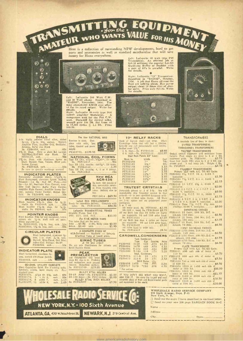
FQUIp ,jesMhTT"G / Hp WANTS VAIUF roe / woo eHis
ON' Here is a collection of outstanding NEW developments, hard to get 11
parts and accessories as well as standard merchandise that will save
1041, money for Hams everywhere. '
Jew
a *ad 4611/ f/* ® 42r .4 a
Left: Lafayette 30 watt type P46 Transmitter. An efficient job at $49.50 utilizing the popular Les -tet Oscillator Buffer or Doubler with a pair of 46's in parallel. Write for details.
Right: Lafayette "19" Transceiver. Described in "RADIO ", October, 1934. A job that Hams all over the Fast are talking about. Has power output about 10 times that of simi- lar units. Price only $17.95. Write for details.
Left: Lafayette 100 Watt C.W. and 30 Watt phone. Described in "RADIO ", November, 1934. The most economical XMTR ever offer- ed for its rated output. Write for details. Right: Lafayette 30 -watt type B46 speech amplifier Modulator. A companion unit for the P46 ('.W. unit. Designed for crystal mike, overall gain 110 Db. fiat from 60 to 17,000 cycles + 1.5 Db. Price $39.50.
DIALS 4 -in. highly polished nickel silver, etched
figures. 11,ís -in. intg. centers. Marked; Amplifier Plate, Amplifier Crid, Oscillator, Antenna. Buffer also Blank. No. PXH9858, each 60c
2 j4-hI. Diam. Same as above but marked; NEUTRALIZATION also Biank. Nn. PXH98S7, each 50e
2% -in. Diaur. with Aluminum figures on black. Marked; Tone, Volume, Mixer gain. Button Current. No. PXI[9859, each 10c Be sure to specify mnrltings wanted
INDICATOR PLATES Rectangular aluminum plates_ If ,zc -In. Black Background, aluminum figures. Marked: Filament -1st (In -22nd Off; Plate -2nd Un -lst Off; (Iscillab,r Plate Current: Amp- lifier Grid Current: Buffer Plate Current; Amplifier Plate Current; Amplifier Screen Cur- rent; Antenna Feeder Current: Output Grd- Grid. No 1'X117,9,. e :u°, 10c
INDICATOR KNOBS Black bakeine 2 jg -iii. diam. for % -io.
shafts. No. PX119895, each 22e Black bakelite 11 /2 -in. diam. for 1/4 -in.
shafts. No. P1{9896, each 17e
POINTER KNOBS Black bakelite. Fine for test equipment, trans- ceivers, etc. '4 -in. shaft with set screw. White engraved line. No. PXMI 3053, 214 -in. long, each 10e !'X213054, I!4 -in. long, each 09e
CIRCULAR PLATES ®Black background, aluminum 0g-
C ores, lain. diam. lin. hole. Marked: Mike- Phone, Cell Disc; Adjust -Cell Voltage; On -Of. l'XII9S99, each 10e
INDICATOR PLATE Black background, aluminum res, marked CW -Phone Switch. 1'X119918, each 15e
GENERAL UTILITY CABINETS Black Crystalline finish. For X'mitting units. leceirers, mixers, input stages, etc. Four -tandard sizes: 1'X122174, 51,e2x 61 51/1, each.. 69e l'XY22175, 5 x On 6, each.. 99e l'XY22176, 8 x101 7, each..1.19 1'X122177, 11 1121 8, each..1.69
The New NATIONAL HRO
Receiver in stork. ('.,m- plete with coils, less
tubes, speaker and power supply.
PXNI3771 $139.50
NATIONAL COIL FORMS Type XR 10A, steatite; 2'yx. "; 26 turns,
No. PXN14347 90c Type XR 12A, steatite; 4x61 /1"; 28 turns.
No. PXN14348 1.35 Type XR 20, steatite; 4, 5 or 6 prongs,
No. PXN14349 21e
NEW RCA ACR -136
In stock. Get details of this remarkable receiv- er. Price complete with tubes. Nothing else to buy.
l'XN13,14 ..$69.50
Latest RCA OSCILLOGRAPH Ready for immediate deli n ry. Complete with
tubes. No. PIN 13043 $84.50
Lafayette TRANSMITTING TUBES Graphite Plates. Real l'.B. 203, 211, 242, 845 $10.95
For FIVE METER HAMS Two tubes that are the nertz. 00 ..$7.50 510C, Molly plate $2.95 866Á..$2.40 866 $1.95
A COMPLETE STOCK OF RCA- DeForest - Raytheon - Sylvania
X'mitting Tubes at lowest prices.
EIMAC TUBES at the best prices!
11 'e are sole Distributors for Atlanta and 5 t rth Eastern States.
PEAK PRESELECTOR
and Preamplifier will boost those RI sigs to 9. Predates and mudenrizes your present receiver. Immediate delivery. No. PXN13760...$19.80
19" RELAY RACKS }lade of higrade steel -not scrap. Itluk Crystalline finish that will last a lifetime. Entirely new and exceptionally good looking. Drilled every l 3'. ".
8 ft. high -No. PXY221S0... $8.95 8 ft. high --No. PXY22151 ... $10.95
Steel Rack Panels 19" Long:
Stock No. Width Cost PXY22160 7" 78c PXY22161 8%" 95c
1.15 1.35 1.55 1.75 1.95 2.10 2.40
PXY22162 PXY22163 PXY22164 PXY22185 PXY221O6 PXY22167 PXY2216R
12!4" 14" 15%" 17%" 191/4" 21"
TRUTEST CRYSTALS Accurately ground to .1 of l';ó. \Ye will immediately ship frequency nearest to that ,rdered --or to your specified frequency with- in 2 days without extra charge. All Xtals are 1-in. square and are guaranteed power oscillators. X or Y cut
40 meter band, No. PXN3989..$3.75 80 -160 m. band. No. PXN13955 $2.75
AT cut Dritt less than 10 cycles per degree per megacycle. SO and 160 meter band. No. PXNII535 .. .$3.25
AT cut Drift less than 4 cycles per degree per megacycle. SO and 160 meter band. No. PXN13536 $5.00 40 meter band to order only. No. PXN13537 $8.50
CARD WE LL CON DEN SE RS Tank Condensers Type Cap Spacing Price
PXII8603 104K 2.20 .070 $2.35 PX118604 14$11 440 .070 4.12 1901860.5 T -199 330 .084 5.88 PX1I8609 T-153 110 .171 5.29
Neut. Condensers PX1I8611 511 -B 23 .171 1.77 PX1I8612 513 -B 50 .171 .3.53
Split Stator PXH8618 197B 80 .470 2.94 PX08017 157B 210 .070 4.70
l'r .aetiom.
BLILEY X'TAL HOLDER 20 -40 Meter -Nn. INN! 1300,..$1.00 IF YOU DON'T SEE WHAT YOU WANT, 00 -160 Meter -No. l'X,NI 13099.. $1.00 ASK FOR IT. We carry the largest and most
BLILEY X'TAL OVEN HOLDER complete stock of Ham and Experimental parts No. PXM13097 $7.50 and equipment in the world.
NEW YORK,N.Y.- 100 Sixth Avenue
TRANSFORMERS A complete I;ne or these In stock:
UNITED TRANSFORMERS
THORDARSON TRANSFORMERS
TRUTEST TRANSFORMERS Trutest special suppressor grid modulator trans- formers. From single 45 plate to 1 or 2 RK suppressor grids. No. PXE3498 $3.75 Same from single 2R6 plate to 1 or 2 RK sup -
nresar grill. A real husky job. Weighs 6 lbs No. PXE5199 $3.75
FILAMENT TRANSFORMERS Primary 115 Volts A.C. 50/60 Cycles
PXE5508 21/a V.C.T. 20 A; 2500 V insulation $1.50
PXE5509 71/i V.C.T. 0.5 A; 2500 V. insulation $1.75
PXE5310 10 V.C.T. 61/1 A; 2500 V insulation $2.00
PXE5511 6.3 V.C.T. 5 A; 5 V.C.T. 6 A: 2500 V. insulation $2.00
PXESS12 21/1 V.C.T. 12 A; 5000 V.
insulation $1.75 PXE5313 5 V.C.T. 3 A; 5 V.C.T. 3 A:
5 C.C.T. 6 A; 2300 V. insalatiou $2.00 PXF ;35 t 4 Three 71,4 V.C.T. 2% Amp.
windings; 2300 V. insulation $2.00 SMOOTHING CHOKES
PXE5515 12 Henry, 200 MA; D.C. re- sistance, 140 ohms $2.50
PXE:5516 12 Henry, 300 MA; D.C. re- sistance, 105 ohms $3.75
PXE5517 12 Henry, 500 MA; D.C. re- sistance, 70 ohms $6.50
INPUT SWINGING CHOKES PXE5518 5/25 Henry, 200 !1[A; D.C. re-
sistance, 140 ohms $2.50 PXEO519 5/25 Henry, 300 MA; D.C. re-
sistance, 105 ohms $3.75 PXE5520 5/25 Henry, 500 MA; D.C. re-
sistance. 70 ohms $6.50 PLATE TRANSFORMERS
P''i'ry 115 V+Its A.C. 50/60 Cycles PXF;352a 800 each side of center at
1..,0 MA $3.75 PXE3322 800 each side of center at
250 MA $5.50 PXE5523 730 or 900 each side of center
at 330 MA $8.50 PXE5524 1250 or 1400 each side of
center at 300 MA $16.00 PXK5525 1600 or 2000 each side ' f
center at 400 MA $21.75 PXE5526 25011 or 3000 each side of
center at 500 MA $32.50 PXE5327 1250 or 1400 each side .$4 3250
at 200 MA $10.00
WHOLESALE RADIO SERVICE COMPANY 100 Sixth Avenue, Dept. P -35 New York, N. Y.
Send me the order I have described in enclosed letter. Send me your new 136 page BARGAIN BOOK 66 -C.
Name
Address ...
City.._ State -...._._.......
a
www.americanradiohistory.com
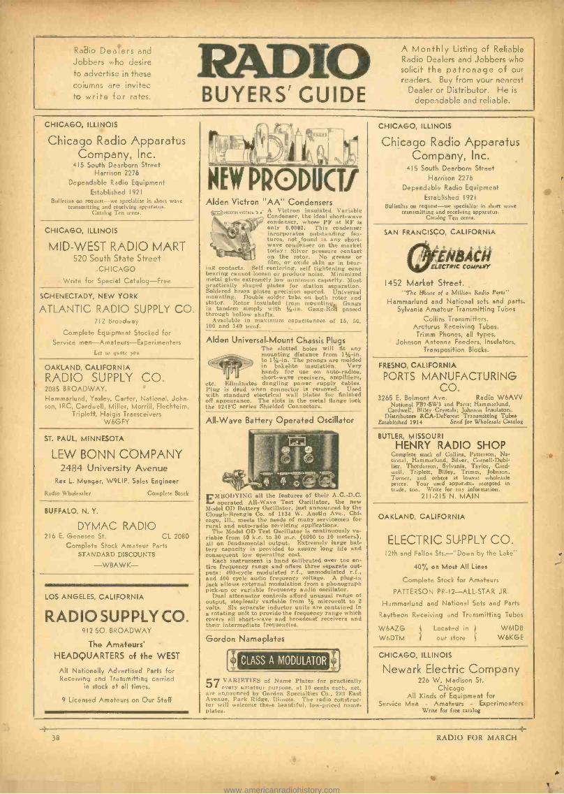
Radio Dealers and
Jobbers who desire to advertise in these
columns are invitee to write for rates.
IO BUYERS' GUIDE
A Monthly Listing of Reliable Radio Dealers and Jobbers who solicit the patronage of our readers. Buy from your nearest
Dealer or Distributor. He is
dependable and reliable.
CHICAGO, ILLINOIS
Chicago Radio Apparatus Company, Inc.
415 South Dearborn Street Harrison 2276
Dependable Radio Equipment Established 1921
Bulletins on request -we specialize in short wave transmitting and receiving apparatus.
Catalog Ten cents.
CHICAGO, ILLINOIS
MID -WEST RADIO MART 520 South State Street
CHICAGO
Write for Special Catalog -Free
SCHENECTADY, NEW YORK
ATLANTIC RADIO SUPPLY CO. 712 Broadway
Complete Equipment Stocked for Service men -Amateurs -Experimenters
Let us quote you
OAKLAND, CALIFORNIA
RADIO SUPPLY CO. 2085 BROADWAY. Hammarlund, Yaxley, Carter, National, John- son, ARC, Cardwell, Miller, Morrill, Flechteim,
Triplett, Haigis Transceivers W6GFY
ST. PAUL, MINNESOTA
LEW BONN COMPANY 2484 University Avenue
Rex L. Munger, W9LIP, Sales Engineer
Radio Wholesaler Complete Stock
BUFFALO, N. Y.
DYMAC RADIO 216 E. Genesee St. CL 2080
Complete Stock Amateur Parts STANDARD DISCOUNTS
-W8AWK-
LOS ANGELES, CALIFORNIA
RADIO SUPPLY CO. 912 SO. BROADWAY
The Amateurs' HEADQUARTERS of the WEST
All Nationally Advertised Parts for Receiving and Transmitting carried
in stock at all times.
9 Licensed Amateurs on Our Staff
NEW PR o DUCT! Alden Victron "AA" Condensers
C ̂wswtssvictrtew xs A Victron insulated Variable ., Condenser, the ideal short -wave condenser, whose PF at RF is only 0.0002. This condenser incorporates outstanding fea- tures, not found in any short- wave condenser on the market today : Silver pressure contact on the rotor. No grease or film, or oxide skin as in bear-
ing contacts. Self centering, self tightening cone bearing cannot loosen or produce noise. Minimized metal gives extremely low minimum capacity. Most practically shaped plates for station separation .
soldered brass plates precision spaced. Universal mounting. Double solder tabs on both rotor and stator. Rotor insulated from angs in tandem simply with % -in. Gang -Ral passed through hollow shafts.
Available in maximum capacitances of 15, 50, 100 and 140 mmf.
Alden Universal -Mount Chassis Plugs The slotted holes will fit any mounting distance from 1VI-in. to 17,4 -in. The prongs are molded in bakelite insulation. Very handy for use on auto -radios, short -wave receivers, amplifiers,
etc. Eliminates dangling power supply cables. Plug is dead when connector is removed. Used with standard electrical wall plates for finished off appearance. The slots in the metal flange lock the 924FC series Shielded Connectors.
All -Wave Battery Operated Oscillator
EMBODYING all the features of their A.C. -D.C. operated All -Wave Test Oscillator, the new
Model OD Battery Oscillator, just announced by the Clough -Brengle Co. of 1134 W. Austin Ave.. Chi- cago, Ill., meets the needs of many servicemen for rural and auto-radio servicing applications.
The Model OD Test Oscillator is continuously va- riable from 50 k.c. to 30 m.c. (6000 to 10 meters) all on fundamental output. Extremely large bat- tery capacity is provided to assure long life and consequent low operating cost.
Each instrument is hand calibrated over the en- tire frequency range and offers three separate out- puts: 400 -cycle modulated r.f., unmodulated r.f., and 400 cycle audio frequency voltage. A plug -in jack allows external modulation from a phonograph pick -up or variable frequency audio oscillator.
Dual attenuator controls afford unusual range of output, steplessly variable from .1/2 microvolt to 2
volts. Six separate inductor units are contained in a rotating unit to provide the frequency range which covers all short -wave and broadcast receivers and their intermediate frequencies.
Gordon Nameplates
57
CLASS A MODULATOR
VARIETIES of Name Plates for practically every amateur purpose, at 10 cents each, net.
are announced by Gordon Specialties C'o., 233 East Avenue, Park Ridge, Illinois. The radio construc- tor will welcome these beautiful, low -priced name- plates.
CHICAGO, ILLINOIS
Chicago Radio Apparatus Company, Inc.
415 South Dearborn Street Harrison 2276
Dependable Radio Equipment Established 1921
Bulletins on request -we specialize in short wale transmitting and receiving apparatus.
Catalog Ten cents.
SAN FRANCISCO, CALIFORNIA
ELECTRIC COMPANY
1452 Market Street. "The Mouse of a Million Radio Parts"
Hammarlund and National sets and parts. Sylvania Amateur Transmitting Tubes
Collins Transmitters. Arcturus Receiving Tubes.
Trimm Phones, all types. Johnson Antenna Feeders, Insulators,
Transposition Blocks.
FRESNO, CALIFORNIA
PORTS MANUFACTURING CO.
3265 E. Belmont Ave. Radio W6AVV National FB7SWI and Parts; Hammarlund.
Cardwell. Bliley Crystals; Johnson Insulators. Distributors RCADeForest Transmitting Tubes
Established 1914 Send for Wholesale Catalog
BUTLER, MISSOURI
HENRY RADIO SHOP Complete stock of Collins, Patterson, Na, tional, Hammarlund, Silver, Cornell -Dubi lier, Thordarson, Sylvania, Taylor. Card- well. Triplett, Bliley, Trimm, Johnson, Turner, and others at lowest wholesale prices. Your used apparatus accepted is trade. too. Write for any information.
211 -215 N. MAIN
OAKLAND, CALIFORNIA
ELECTRIC SUPPLY CO. I2th and Fallon Ste.- "Down by the Lake'
40% on Most All Lines
Complete Stock for Amateurs
PATTERSON PR -12- ALL -STAR JR.
Hammarlund and National Sets and Parts
Raytheon Receiving and Transmitting Tubes
W6AZG W6DTM
Located in
t our store
W6IDB W6KGE
CHICAGO, ILLINOIS
Newark Electric Company 226 W. Madison St.
Chicago All Kinds of Equipment for
Service Men - Amateurs - Experimenters Write for free catalog '-
38
e
4 RADIO FOR MARCH
www.americanradiohistory.com
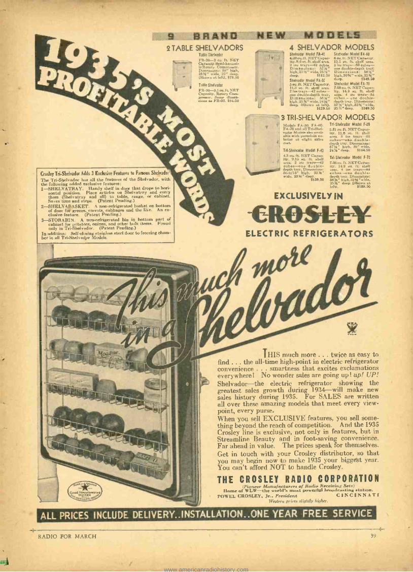
9 BRAND 2 TABLE SHELVADORS
Table Shelrador
FR -20 -2 cu. ft. NET C pacity.$emi-hermet- ie Rotary Compressor. Dimensions: 36" high, 234" wide, 25" deep. (Shown nt left). $79.50
Table Shelvador
FR-3(}--3.1 eu. ft. NET Capacity. Rotary ('om- prennor. . dimen- sions an PIt0. $94.50
Crosley Tri -Shelvador Adds 3 Exclusive Features to Famous Shelvador
The Tri-Shelvador has all the features of the Shelvador, with the following added exclusive features: 1 -SHELVATRAY. Handy shelf in door that drops to hori-
zontal position. Place articles on Shelvatray and carry them ( Shelvatray and all) to table, range, or cabinet. Saves time and steps. (Patent Pending.)
2- SIIELVABASKET. A non -refrigerated basket on bottom of door fol greens, carrots, cabbages and the like. An ex- clusive feature. (Patent Pending.)
3 -STORABIN. A non -refrigerated bin in bottom part of cabinet for potatoes, onions, and other bulk items. Found only in Tri- Shelvador. (Patent Pending.)
In addition: Self -closing stainless steel door to freezing cham- ber in all Tri-Shelvador Modela.
NEW MODELS 4 SHELVADOR MODELS
u
41s
T S'
(
4¡
ti
Shelrador Model FA -40 4.09 cu. ft. NET Capac- ity. 8.6 so. f t. shelf area. 2 ice trays -42 cubes. Dimensions: 525e' high, 23 )S" wide, 2554" dreg. $112.50 Shelvador Model FA -50 5 cu. ft. NET Capacity. 11.3 al. ft. shelf area. 2 ice traye -42 cubex- one double -depth tray. Dimensions: 564" high, 25'o "wide, 24 4" deep. (Shown at left).
6129.50
Shelrador Model FA -60 e cu. ft. NET ('apacity. 13.5 ea. ft. nh.-If area. 3 ice trays -63 cubes one double -depth tray. Dimensions: 56tí" high,30D4 "wide, 254" deep. 6149.50 Shelrador Model FA -70 7.08 cu. ft. NET (' apeo- ity. 14.9 su. ft. shelf an . 4 ice trays -84 cubes. -one double - depth tray. Dimensioa: 57 IS" high, 3251 " wide, 25 ' deep. $169.50
3 TRI- SHELVADOR MODELS TrI-Shelvador Model F -55 5lodeLs Ft -50, FA-1)0,
FA -70 and all Tri-Shel- vador 56sfeb also avail - able with porcelain ex- terior at slight extra coat.
5.51 cu. ft. NET Capac- ity. 11.6 ea. ft. shelf area. 3 ice trays -:3 cubes -one double - depth tray. Dimensiono: 5754' high, 29' wide,
Td-Shelvador Model F-43 2434' deep. 6164.50 4.3 eu. ft. NET Capac- ity. 9.15 sq. ft. shelf area. 2 ice trays --42 cubes -one double- depth tray. Dimensions: 56 -9/16' high, 23 4' wide, 234' deep.
6139.50
Trl- Shelrador Model F -70
7.08 cu. ft. NET Capac- ity. 14.9 sq. ft. shelf area. 4 lea trays --84 cubes -one double - depth trey. Dimensions: 511'.' high, 32', "wide. 5'4' deep. (Shown at
left). $189.50
EXCLUSIVELY IN
-CROSELE1F ELECTRIC REFRIGERATORS
g` F pwiow ase) EA
F !
EE- 71! 1§61N
THIS much more . e . twice as easy to find ... the all-time high -point in electric refrigerator convenience ... smartness that excites exclamations everywhere! No wonder sales are going up ! up! UP! Shelvador -the electric refrigerator showing the greatest sales growth during 1934 -will make new sales history during 1935. For SALES are written all over these amazing models that meet every view- point, every purse. When you sell EXCLUSIVE features, you sell some- thing beyond the reach of competition. And the 1935 Crosley line is exclusive, not only in features, but in Streamline Beauty and in foot -saving convenience. Far ahead in value. The prices speak for themselves. Get in touch with your Crosley distributor, so that you may begin now to make 1935 your biggest year. You can't afford NOT to handle Crosley.
THE CROSLEY RADIO CORPORATION ¡Pioneer Manufacturers of Radio Receiving Sets
Home of WLW -the world's most powerful broadcasting station. POWEL CROSLEY, Jr., President CINCINNATI
IVeslern prices slightly higher.
ALL PRICES INCLUDE DELIVERY..INSTALLATION..ONE YEAR FREE SERVICE
RADIO FOR MARCH
-
39 4--
www.americanradiohistory.com
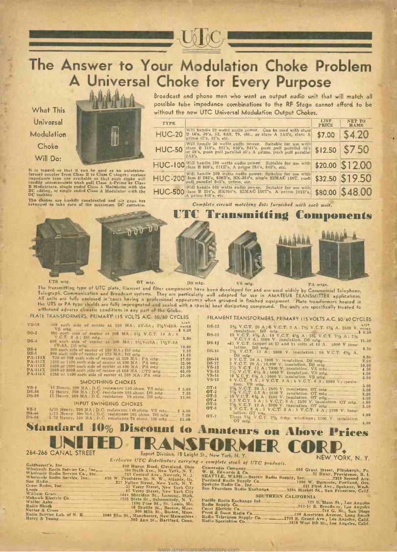
The Answer to Your Modulation Choke Problem A Universal Choke for Every Purpose
What This
Universal
Modulation
Choke
Will Do:
It is tapped so that it can be used as an autotrans- former coupler from Class B to ('lass (' stages; various impedance taps are available so that each choke will readily accommodate push pull Class A -Prime or ('lass B Modulators, single ended Class A Modulator with the DC adding. or single ended ('lass A Modulator with the D(' bucking. The chokes are huskily constructed and air gaps are arranged to take care of the maximum DC currents.
Broadcast and phone men who want an output audio unit that will match all
possible tube impedance combinations to the RF Stage cannot afford to be without the new UTC Universal Modulation Output Chokes.
TYPE LIST NET TO PRICE HAMS
HUC-20
HUC-50
HUC-I00
Will handle 20 watts audio power. Can be used with class B 46's, 59's. 53, 6A6, 79, etc., or class A 2A3's, class A prime 42's. 46's, etc.
HUC-200
Will handle 50 watts audio power. Suitable for use with class B 210's, 801's, 830's, 841's, push pull parallel 46's or 59's, push pull parallel 45's A prime, push pull parallel 2A3's.
Will handle 100 watts audio power. Suitable for use with class 13 800's, 211E's, A priSpe 284's. 845's, etc.
Will handle 200 watts audio power. Suitable for use with 'lass B 203's, 830B's, HK- 354'a, single EIMAC 150T, push pull parallel 845's, prime, etc. Vill handle 600 watts audio power. Suitable for use with
HUC- 500, 'lass B 204's, HK354'a, EIMAC 150T's, A prime 212D's, IA prime 849's, etc.
$7.00 $4.20
$12.50 $ 7.50
$20.00 $1 2.00 $32.50 $19.50 $80.00 $48.00
Complete circuit matching dots furnished with each unit,
UTC Transmitting Components
UTS mtg. (1'f mtg. DS mtg. VS mtg. PA mtgs. The transmitting type of UTC plate, filament and filter components have been developed for and are used widely by Commercial Telephone, Telegraph, Communication and Broadcast systems. They are particularly well adapted for use in AMATEUR TRANSMITTER applications. All units are fully enclosed in cases having a professional appearanc when grouped in finished equipment. Plate transformers housed in the UTS or PA type shields are fully impregnated and sealed with a spacial heat dissipating compound. The units are specifically treated to withstand adverse climatic conditions in any part of the Globe.
PLATE TRANSFORMERS, PRIMARY 115 VOLTS A.C. 50, 60 CYCLES FILAMENT TRANSFORMERS, PRIMARY 115 VOLTS A.C. 50/60 CYCLES LILT VS-10
DS-2
DS-3
DS-4 DS-5 PA-111X PA-112X PA-113X PA-114 X PA-116X
VS-1 DS-30 DS-50
VS-2 DS-40 DS-60
450 each side of center at 15, M: \; \'_:;: \; \. PRICE VS mtg. .._.__ t 6.50
500 each side of center at 20ß M.'\ : 2' c V.( .'l'. 11 A : 5 V.C.T. 3 A ; DS mtg.. 8.00
600 each side of center at 2.00 MA ; 2 V -I,A ; 71 /s V -3A 6V -3A. DS mtR ... .................._..........._
. 10.00 800 each side of center at 150 MA ; DS mtg. 7.50 800 each side of center at 250 MA ; DS mtg. 11.00 750 or 900 each side of center at 350 MA ; PA mtg. 17.00
1250 or 1400 each side of center at 500 MA : PA mtg. 32.00 1600 or 2000 each side of center at 400 MA ; PA mtg. 43.50 2500 or 3000 each side of center at 500 MA ; UTS mtg. 65.00 1250 or 1400 each side of center at 200 MA ; PA mtg. 20.00
SMOOTHING CHOKES 12 Henry, 200 MA ; D.C. resistance 140 ohms. VS mtg..__... $ 5.00 12 Henry. 300 MA ; D.C. resistance 105 ohms. DS mtg.._ _..._ 7.50 12 Henry, 500 MA : D.C. resistance 70 ohms. DS mtg. 13.00
INPUT SWINGING CHOKES 5/25 Henry, 200 MA ; D.C. resistance 140 ohms. VS mtg. E 5.00 5/25 Henry, 300 MA ; D.C. resistance 105 ohms. DS mtg ._ 7.50 6/25 Henry. 5u0 MA; D.C. resistance 70 ohms. DS mtg. _ 13.00
LIST DS-12 21/2 V.C.T. 20 A;4i V.C.T. 3 A; 7% V.C.T. 6% A. 2500 V. sums insulation. DS mtg. 4 8.50 DS-13 10 V.C.T. 6% A; 10 V.C.T. 6% A; 7t. V.C.T. 2% A; 2% V.C.T.5 A; 2500 V. insulation. DS mtg. ......__ ..................._......._.. 11.50 DS-14 11 V.C.T. tapped at 12 and 14 volts at 10 A. 6000 V insu- lation. DS mtg..... 8.50 DS-15 2% V.C.T. 12 A ; 5000 V. insulation: 10 V.C.T. 6% A.
DS mtg. _.. .. ...
-N-r. _.._.. 8.00 DS-16 5 V.C.T. 20 A; 7000 insulation. DS mtg 7.50 DS-17 5 V.C.T. 20 A; 10,000 V. insulation. DS mtg 10.00 VS-12 2% V.C.T. 12 A; 7000 V. insulation. VS mtg. 4.50 VS-13 7% V.C.T. 6% A; 6000 V. insulation. VS mtg. 4.5t1 VS-14 10 V.C.T. 6% A ; 6000 V. insulation. VS mtg.- 5.Ou VS-15 5 V.C.T. 3 A: 5 V.C.T. 3 A; 5 V.C.T. 6 A ; 6000 V. insula- tion. VS mtg. .... _ ...._.._ _.... 5.00 OT-1 2t,5 V.C.T. 20 A; 2500 V. insulation. OT mtg. 3.00 OT-2 7t,5 V.0 T. 6.5 A; 2500 V. insulation. OT mtg...._......___.._..__.. 3.50 OT-3 10 V.C.T. 6% A; 2600 V. insulation. OT mtg.. 4.011 OT-4 6.3 V.C.T. 5 A : 5 V.C,T. 6 A; 2600 V. insulation. OT mtg. 1.00 OT-5 2>fj V.C.T. 12 A ; 5000 V. insulation. OT mtg. 3.50 OT-6 5 V.C.T. 3 A ; 5 V.C.T. 3 A; 5 V.C.T. 6 A; 2500 V. insu- lation. OT mtg. - _. ... 4.01t OT-7 Three 7t[. v r T w. n._.. ...:_d:_ . ...... .. . .
. .....
an 1.00 Standard 10% Discount to Amateurs on Above Prices
IJI1IEID TRANSFORWER CORIP. 264-266 CANAL STREET
Goidhamer's, Inc. Wholesale Radio Service ( o., 'er. Wholesale Radio Service ('o., Inc. Wholesale Radio Service, Inc. Sun Radio Gross Radio, Inc.. Leeds .
William (.ram Mohawk Electric Co. Walter Aspe. Radio Shack Nutter & Cross Radio Service Lab. of N. H. Harry & Young
Export Division 15 Laight St., New York, N. Y. NEW YORK N rchuir'e UTC distributors carrying 610 Huron Road, Cleveland, Ohio
100 Sixth Ave., New York, N. Y. 219 Central Ave., Newark, N. J.
130 W. Peachtree St. N. W., Atlanta, Ga. 227 Fulton Street, New York, N. Y.
51 Vesey Street, New York City 45 Vesey Street, New York City
1444 Sheridan St., Lansing, Mich. 1335 State St., Schenectady, N. Y.
1100 Pine St., St. Louis, Mo. 46 Brattle St., Boston, Mass.
900 Milk St., Boston, Mass. 1008 Elm St., Manchester, New Hampshire
203 Ann St., Hartford, Conn.
a complete stock of UTC products. Y
Cameradio Company 6113 (.rant Street. Pittsburgh, Pa. W. H. Edwards & Co. 32 Bway, Providence, R. I. SEATTLE, WASH. -Seattle Radio Suppl), Inc. 2319 Second Ave. Portland Radio Supply ('o. __.1300 W. Burnside, Portland, Ore. Spokane Radio ('o., Inc.. 611 First Ave., Spokane, Wash. ........... San Francisco Radio Exchange 1284 Market St., San Francisco, Calif.
SOUTHERN CALIFORNIA Pacific Radio Exchange Inc.. . 729 S. Main St., Los Angeles Radio Supply Co. _ _. 912-14 S. Broadway, Los Angeles Coast Electric Co. _....... 744 G. St., San Diego Prest & Dean Radio Co. .400 American Avenue, Long Beach Radio Television Supply Co. .1701 S. (:rand Ave., Los Angeles, Calif. Radio Specialties Co 1816 West 8th St., Los Angeles, Calif.
'
www.americanradiohistory.com