fibreC Technical Manual - slovenia.ravagobuildingsolutions.com · Beton lebt. fibreC Technical...
81
Beton lebt. fibreC Technical Manual Application Fastening Handling Beton lebt.
Transcript of fibreC Technical Manual - slovenia.ravagobuildingsolutions.com · Beton lebt. fibreC Technical...
Beton lebt.
fibreC Technical ManualApplicationFasteningHandling
Beton lebt.

NoteThis brochure contains basic descriptions and information on fibreC glassfibre reinforced concrete panels.
The descriptions of the product characteristics should not be con-sidered as a guarantee. All information, including technical informa-tion and drawings, is up to date and based on our own experience. The service provided by Rieder Smart Elements GmbH extends to fibreC panels but explicitly not to fastening materials or substructures. The applications described here are examples only and do not take account of the specific conditions associated with individual cases. The information and suitability of the material for the intended use must be checked with respect to each individual country and project. Despite careful checking, we cannot accept liability for
accuracy, completeness or actuality. This applies, in particular, to print errors and subsequent changes to technical information. Reference to this will be made in the contract to the agreement to be concluded, which takes precedence over information provided here.
Please get in touch with your local Rieder sales partner or contact Rieder directly for more information on sales terms, availability and prices, etc. The latest version of these technical documents is avail-able for download under www.rieder.cc.
04/2015
fibreC cladding
The following pages will help select your fibreC cladding: from choosing the material up to applying and maintaining the facade.
This brochure will provide information on…
• Product details
• Information on glassfibre reinforced concrete
• Design options with fibreC
• Areas of application
• Structural requirements
• Fastening details
• Handling and fastening the cladding panels onsite
• Quotation and ordering phase
• Handling fibreC panels (from transport to application)
• Cleaning fibreC panels
• The contact person to answer your questions
We look forward to your feedback and ideas! We listen!
3
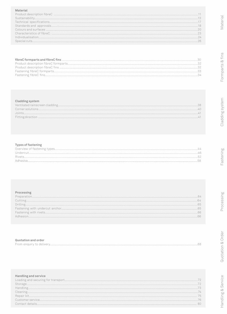
Material Product description fibreC ....................................................................................................................................................................................11Sustainability..............................................................................................................................................................................................................13Technical specifications.........................................................................................................................................................................................17Standards and approvals........:..............................................................................................................................................................................18Colours and surfaces .............................................................................................................................................................................................20Characteristics of fibreC. ......................................................................................................................................................................................23Individualisation.....................................................................................................................................................................................................24Special cuts..............................................................................................................................................................................................................26
Types of fasteningOverview of fastening types..................................................................................................................................................................................44Undercut..................................................................................................................................................................................................46Rivets...........................................................................................................................................................................................................52Adhesive..........................................................................................................................................................................................................................58
ProcessingPreparation.............................................................................................................................................................................................................64Cutting............................................................................................................................................................................................64Drilling.............................................................................................................................................................................................................65Fastening with undercut anchor..........................................................................................................................................................................65Fastening with rivets..............................................................................................................................................................................................66Adhesion..........................................................................................................................................................................................................66
Quotation and orderFrom enquiry to delivery........................................................................................................................................................................................68
Form
part
s &
fins
Cla
ddin
g sy
stem
Fast
enin
gP
roce
ssin
gQ
uota
tion
& O
rder
Mat
eria
l
Handling and serviceLoading and securing for transport......................................................................................................................................................................72Storage......................................................................................................................................................................................................72Handling.......................................................................................................................................................................................................73Cleaning.....................................................................................................................................................................................................................74Repair kit................................................................................................................................................................................................................. 75Customer service.....................................................................................................................................................................................................76Contact details....................................................................................................................................................................................................... 80
Cladding systemVentilated rainscreen cladding..............................................................................................................................................................................38Corner solutions ......................................................................................................................................................................................................40Joints........................................................................................................................................................................................................................41Fitting direction .......................................................................................................................................................................................................41
Han
dlin
g &
Ser
vice
fibreC formparts and fibreC fins .........................................................................................................................................................................30 Product description fibreC formparts..................................................................................................................................................................32Product description fibreC fins ............................................................................................................................................................................32Fastening fibreC formparts...................................................................................................................................................................................33Fastening fibreC fins..............................................................................................................................................................................................34
4
5
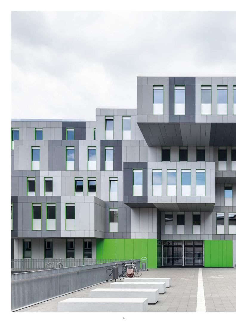
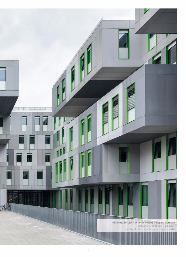
Students Service Center University Cologne | GermanySchuster Architects | Düsseldorf
7,500 m² fi breC facade | various grey shades
6
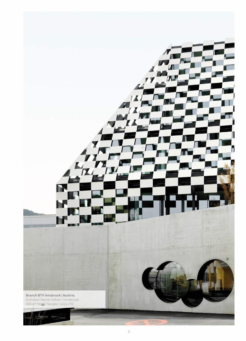
Branch BTV Innsbruck | AustriaArchitect Rainer Köberl | Innsbruck350 m² fi breC facade | ivory | FE

7
Material Product description fibreC ....................................................................................................................................................................................11Sustainability..............................................................................................................................................................................................................13Technical specifications.........................................................................................................................................................................................17Standards and approvals.......................................................................................................................................................................................18Colours and surfaces .............................................................................................................................................................................................20Characteristics of fibreC. ......................................................................................................................................................................................23Individualisation.....................................................................................................................................................................................................24Special cuts..............................................................................................................................................................................................................26
Mat
eria
l
8
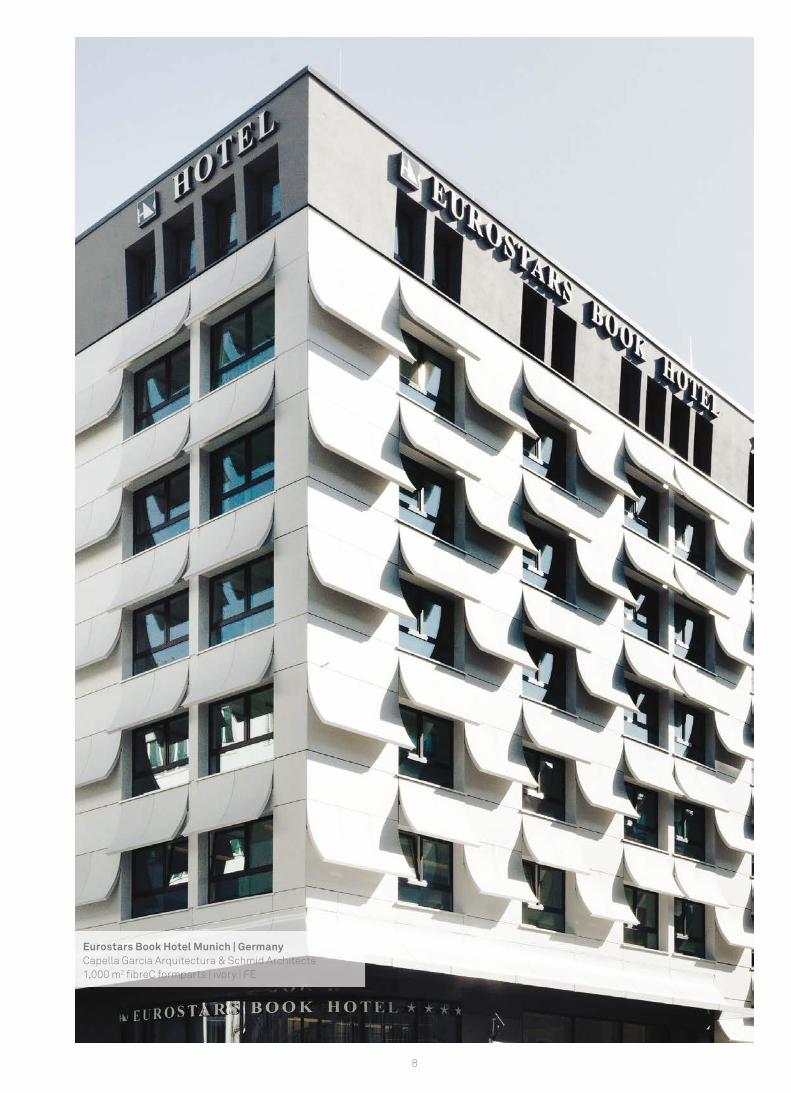
Eurostars Book Hotel Munich | GermanyCapella Garcia Arquitectura & Schmid Architects1,000 m2 fi breC formparts | ivory | FE
9
Mat
eria
lfibreC - Revolution in concrete
fibreC is a glassfibre reinforced concrete material that unites the advantages of both glassfibres and concrete. Behind the develop-ment of fibreC lies the vision of creating a light and stable concrete cladding panel that withstands the effects of weather and environ-mental conditions, while combining durability and valuable design.
Glassfibre reinforced concrete: slender and strongConcrete is made from natural materials and has been used by peo-ple for many years. The first experiments with glassfibre reinforced concrete were made more than three decades ago. Wolfgang Rieder took stock of the results of these experiments and pushed on with the development of the material. Using top-class technology, the Rieder group made glassfibre reinforced concrete suitable for new areas of application. The characteristics of fibreC, its quality, wide range of design options and durability offer new, original and cutting-edge ways of using concrete that were unimaginable just a short time ago.
Glassfibre reinforced concrete as a building materialThe classic material concrete exhibits good compressive strength, but is also brittle and has a low tensile strength. This disadvantage is overcome with the production of a composite material consist-ing of concrete and a tension-resistant layer. Glassfibre reinforced concrete is made from cement-bonded fine concrete reinforced with alkali-resistant glassfibres. Unlike steel fibres, glassfibres provide a distinct advantage in that they do not require anti-corrosion treat-
ment. A concrete cover for concrete components with metallic rein-forcements is no longer required. This means concrete elements can be thin, slender and light. The use of mineral raw materials, natural stone components and glassfibre reinforcements guarantees quality that meets the highest requirements. The wide range of applications for fibreC nurtures the joy of creative experimentation.
A safe material90% of fibreC glassfibre reinforced concrete consists of sand and cement; the remaining 10% is made of glassfibres, pigments and concrete additives. This makes the panels robust and extremely durable. fibreC withstands enormous pressure with a minimum thickness and extremely large panel size. The material guarantees absolute safety thanks to its excellent thermal values, offering tem-perature stability of up to 350° C. fibreC glassfibre reinforced con-crete is not flammable.
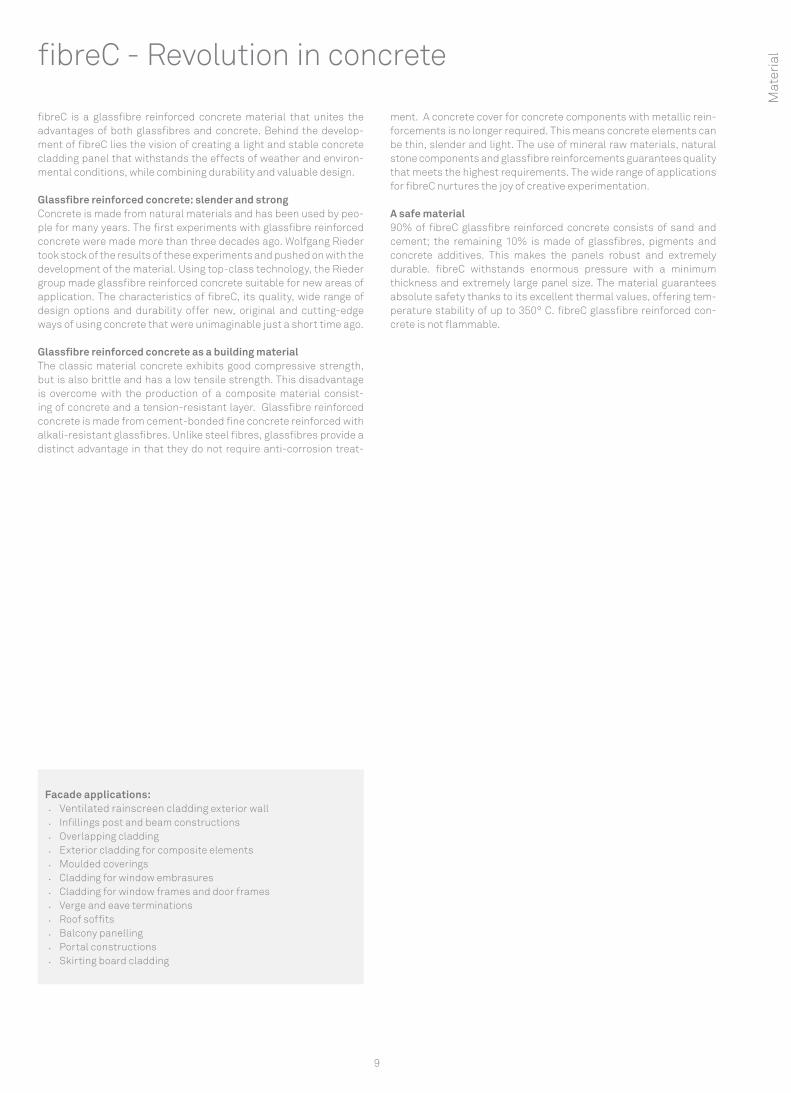
Facade applications: • Ventilated rainscreen cladding exterior wall • Infillings post and beam constructions • Overlapping cladding • Exterior cladding for composite elements • Moulded coverings • Cladding for window embrasures • Cladding for window frames and door frames• Verge and eave terminations • Roof soffits • Balcony panelling • Portal constructions • Skirting board cladding
10
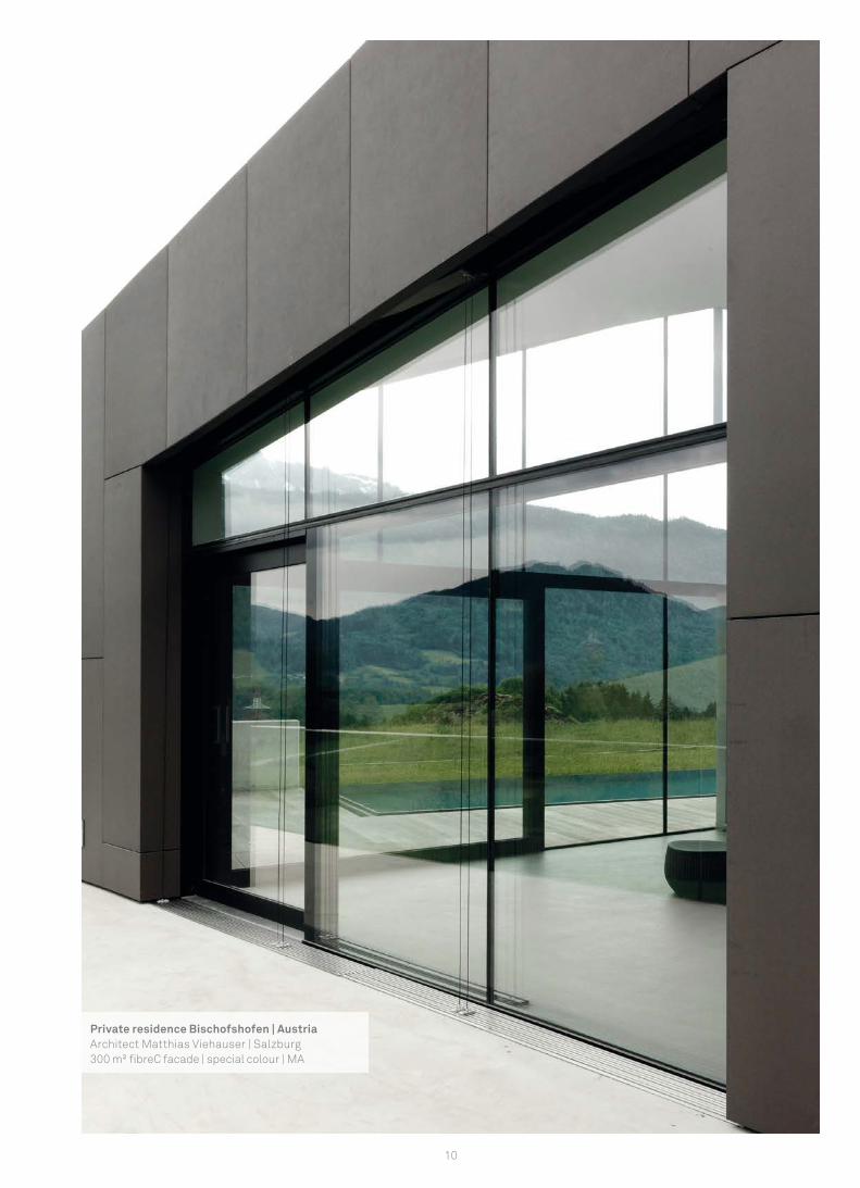
Private residence Bischofshofen | AustriaArchitect Matthias Viehauser | Salzburg300 m² fi breC facade | special colour | MA
11
Mat
eria
lProduct description fibreC
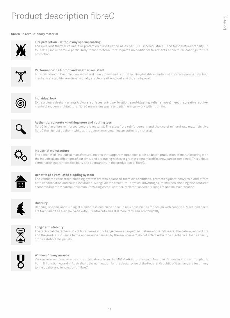
fibreC - a revolutionary material
Fire protection – without any special coatingThe excellent thermal values (fire protection classification A1 as per DIN - incombustible - and temperature stability up to 350° C) make fibreC a particularly robust material that requires no additional treatments or chemical coatings for fire protection.
Performance: hail-proof and weather-resistant fibreC is non-combustible, can withstand heavy loads and is durable. The glassfibre reinforced concrete panels have high mechanical stability, are dimensionally stable, weather-proof and thus hail-proof.
Individual look Extraordinary design variants (colours, surfaces, print, perforation, sand-blasting, relief, shapes) meet the creative require-ments of modern architecture. fibreC means designers and planners can work with no limits.
Authentic: concrete – nothing more and nothing less fibreC is glassfibre reinforced concrete material. The glassfibre reinforcement and the use of mineral raw materials give fibreC the highest quality – while at the same time remaining an authentic material.
Industrial manufacture The concept of “industrial manufacture“ means that apparent opposites such as batch production of manufacturing with the industrial specifications of our time, and producing with ever greater economic efficiency, can be combined. This unique combination guarantees flexibility and spontaneity in the production of fibreC.
Benefits of a ventilated cladding systemThe ventilated rainscreen cladding system creates balanced room air conditions, protects against heavy rain and offers both condensation and sound insulation. Alongside the structural-physical advantages, rainscreen cladding also features economic benefits: controllable manufacturing costs, weather-resistant assembly, long life and no maintenance.
Ductility Bending, shaping and turning of elements in one piece open up new possibilities for design with concrete. Machined parts are tailor made as a single piece without mitre cuts and still manufactured economically.
Long-term stability The technical characteristics of fibreC remain unchanged over an expected lifetime of over 50 years. The natural signs of life and the gradual influence to the appearance caused by the environment do not affect either the mechanical load capacity or the safety of the panels.
Winner of many awards Various international awards and certifications from the MIPIM AR Future Project Award in Cannes in France through the Form & Function Award in Australia to the nomination for the design prize of the Federal Republic of Germany are testimony to the quality and innovation of fibreC.

12
City Hall Kolbermoor | GermanyBehnisch Architects | Stuttgart1,000 m² fi breC facade | polar white, ivory, liquide black, green
13
Sustainability
Holistic approachOur principle of sustainability and our responsibility towards the environment are backed by the international environmental man-agement certificate ISO 14001. We set ourselves high standards in the protection of the environment and use innovative technologies with ecological responsibility. fibreC, unlike most of the products available on the market, is based on mineral base materials and it is fully recyclable. Profitability and sustainability are promoted by the economical use of resources.
The variety and efficiency achieved with fibreC facilitate high- quality, visually attractive, lasting and cost-effective construc-tions. This shows how the authentic material fibreC meets the current trend for natural, environmentally-friendly and sustain-able, value for money materials, creating an aesthetic and modern effect.
• Environmental management certificate ISO 14001
• Environmental Product Declaration EPD ISO 14025 & EN 15804
• IBO - Certificate from the IBO Institute in Vienna
• Emission analyses (VOC) according to the basic principles of the German Construction Technology Institute (DIBt)
• Listed in the GreenSpec® Product list / Leed Points
• Sustainability fact sheet for building certification scheme LEED v4®
• Use of exclusively high-quality raw materials
• From mineral components
• Can be 100 % recycled
• Long-term stability
• Low maintenance costs
• 90 % thinner than similar concrete panels
Concrete has never been so green! M
ater
ial
14
A look at the green facts
fibreC close to nature
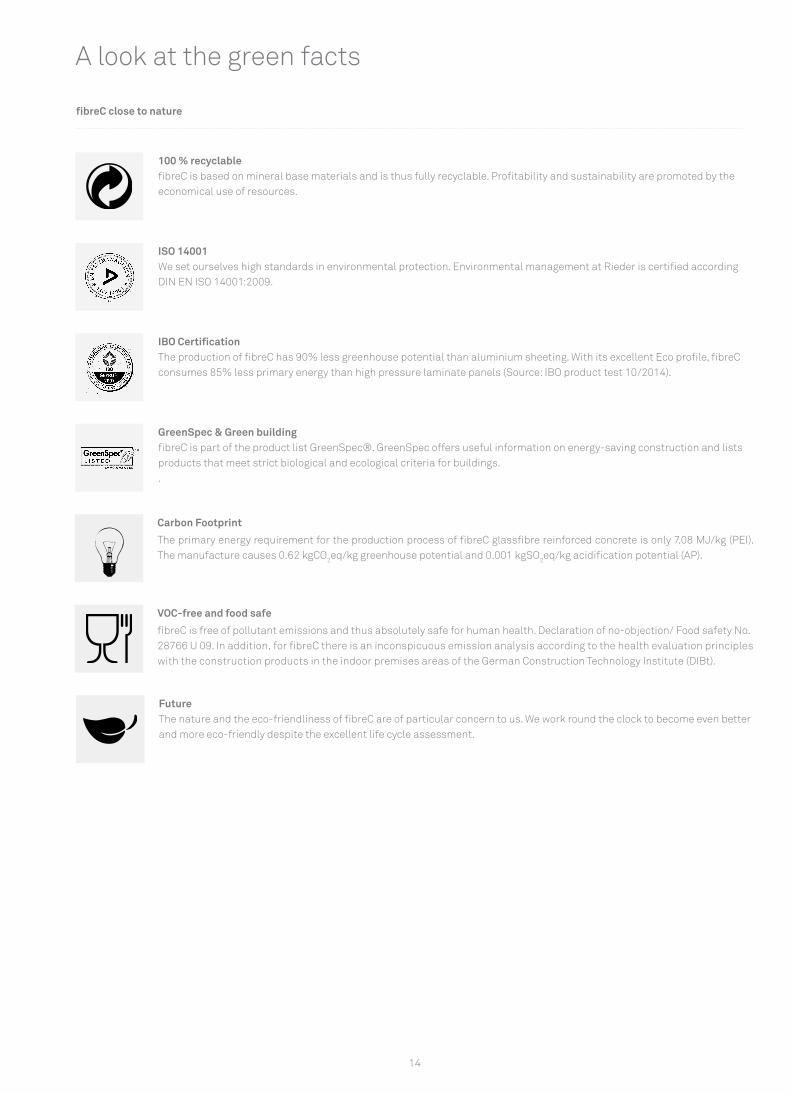
100 % recyclable fibreC is based on mineral base materials and is thus fully recyclable. Profitability and sustainability are promoted by the economical use of resources.
ISO 14001 We set ourselves high standards in environmental protection. Environmental management at Rieder is certified according DIN EN ISO 14001:2009.
IBO Certification The production of fibreC has 90% less greenhouse potential than aluminium sheeting. With its excellent Eco profile, fibreC consumes 85% less primary energy than high pressure laminate panels (Source: IBO product test 10/2014).
GreenSpec & Green building fibreC is part of the product list GreenSpec®. GreenSpec offers useful information on energy-saving construction and lists products that meet strict biological and ecological criteria for buildings..
Carbon Footprint
The primary energy requirement for the production process of fibreC glassfibre reinforced concrete is only 7.08 MJ/kg (PEI). The manufacture causes 0.62 kgCO2eq/kg greenhouse potential and 0.001 kgSO2eq/kg acidification potential (AP).
VOC-free and food safe
fibreC is free of pollutant emissions and thus absolutely safe for human health. Declaration of no-objection/ Food safety No. 28766 U 09. In addition, for fibreC there is an inconspicuous emission analysis according to the health evaluation principles with the construction products in the indoor premises areas of the German Construction Technology Institute (DIBt).
FutureThe nature and the eco-friendliness of fibreC are of particular concern to us. We work round the clock to become even better and more eco-friendly despite the excellent life cycle assessment.
0,01
0,02
0,03
0
fibreC Aluminium Fibre Cement HPL
+2.680%
+ 200%
+ 1.110%
0,001
1,258
kgSO2eq/kg
0,003
0,0278
80
100
60
40
20
0
fibreC Aluminium Fibre Cement HPL
+1.091%
+ 77%
+ 608%
7,08
84,34
12,56
50,12
MJ/kg
8
10
6
4
2
0
fibreC Aluminium Fibre Cement HPL
+858%
+ 62%+110%
0,62
5,97
1,01 1,31
kgCO2eq/kg
15
Life cycle assessment
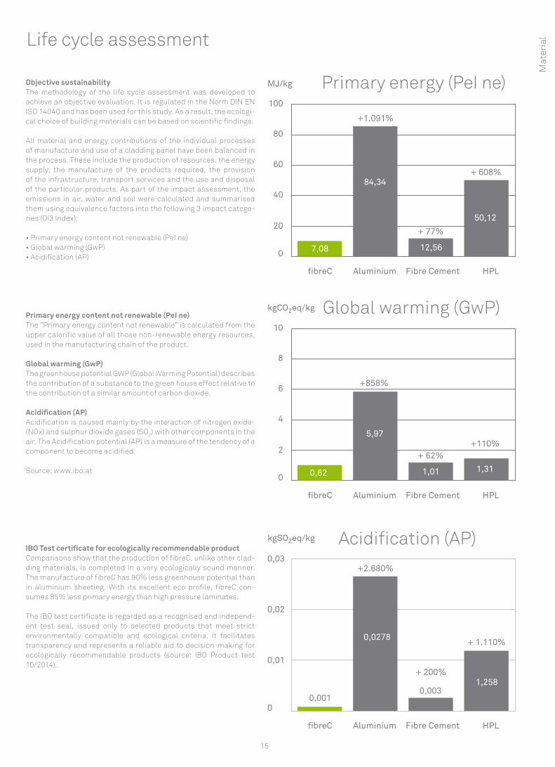
Objective sustainability The methodology of the life cycle assessment was developed to achieve an objective evaluation. It is regulated in the Norm DIN EN ISO 14040 and has been used for this study. As a result, the ecologi-cal choice of building materials can be based on scientific findings.
All material and energy contributions of the individual processes of manufacture and use of a cladding panel have been balanced in the process. These include the production of resources, the energy supply, the manufacture of the products required, the provision of the infrastructure, transport services and the use and disposal of the particular products. As part of the impact assessment, the emissions in air, water and soil were calculated and summarised them using equivalence factors into the following 3 impact catego-ries (OI3 Index):
• Primary energy content not renewable (PeI ne) • Global warming (GwP) • Acidification (AP)
Primary energy content not renewable (PeI ne) The ”Primary energy content not renewable” is calculated from the upper calorific value of all those non-renewable energy resources, used in the manufacturing chain of the product.
Global warming (GwP) The greenhouse potential GWP (Global Warming Potential) describes the contribution of a substance to the green house effect relative to the contribution of a similar amount of carbon dioxide.
Acidification (AP) Acidification is caused mainly by the interaction of nitrogen oxide- (NOx) and sulphur dioxide gases (SO2) with other components in the air. The Acidification potential (AP) is a measure of the tendency of a component to become acidified.
Source: www.ibo.at
IBO Test certificate for ecologically recommendable product Comparisons show that the production of fibreC, unlike other clad-ding materials, is completed in a very ecologically sound manner. The manufacture of fibreC has 90% less greenhouse potential than in aluminium sheeting. With its excellent eco profile, fibreC con-sumes 85% less primary energy than high pressure laminates.
The IBO test certificate is regarded as a recognised and independ-ent test seal, issued only to selected products that meet strict environmentally compatible and ecological criteria. It facilitates transparency and represents a reliable aid to decision-making for ecologically recommendable products (source: IBO Product test 10/2014).
Primary energy (PeI ne)
Global warming (GwP)
Acidification (AP) M
ater
ial
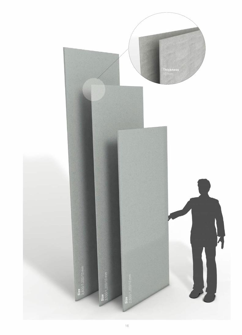
16
Siz
e2,
500/
1,20
0/13
mm
Thickness13 mm
Siz
e3,
100/
1,20
0/13
mm
Siz
e3,
600/
1,20
0/13
mm

17
Technical specifications*2.5 x 1.2 m, 3.1 x 1.2 and 3.6 x 1.2 on request± 3 mm± 2 mm± 3.5 mm ± 4 mm± 5 mm± 6 mm
13 mm (10 mm on request)± 1.3 mm± 0.1 %± 2 mm/m
± 2 mm± 4 mm± 8 mm0.384 mm/m0.737 mm/m2.0 - 2.42 kg/dm³> 18 N/mm² (MOR*) approx. 10,000 N/mm²approx. 30,000 N/mm² 26 - 31.5 kg/m² 10*10^(-6) 1/°k A1 - incombustible | A2-s1,d0 - incombustible according to humidity up to 350°C approx. 1,000 Joule / (kg*K) lambda: approx. 2.0 W / (m*K) 0,05 %
givengivengivengivenUV-light resistant colour pigmentsgivengiven
RivetsAdhesive, Undercut anchorAluminum, steelmin. 8 mm
With alkali-resistant glassfibres (AR glass), technical approved
Cut edges are unfinished and sharp-edged with a coarseness of about 1 mm on the visible face. Glassfibres may emerge at the edges.
Through coloured panels;12 standard colours; special colours on request.
MA Matt: brushed / smooth surface, natural blushing effect (excl. formparts) FL Ferro Light: sandblasted at lower pressure, surface is finer than FE (excl. formparts) FE Ferro: sandblasted at higher pressure, surface is rougher
Hydrophobicity
Sizes Special sizesDimensional variation length (3.6 m) Dimensional variation width (1.2 m) Diagonal difference < 1.5 mDiagonal difference > 1.5 mDiagonal difference > 2.5 m Diagonal difference > 3.6 m Thickness Thickness tolerance Edge straightness (Level 1) Perpendicularity (Level 1)
Physical characteristics Tolerances facing > 0.6 mTolerances facing > 1.2 mTolerances facing > 3.6 mSwellingShrinkage Bulk densityBending tensile strength E-modulus for deformation calculationE-modulus for restraint calculationDead load / mass per unit area (13 mm)Thermal expansion coefficient Building material class (panel |system) Temperature stability Specific heat capacity Thermal conductivityMoisture expansion Weather-resistance Water impermeability Heat-rain-alternate test Frost resistance Frost-defrost-alternate test UV-light resistance Hot water resistanceWet storage resistance
Fastening Fastening visible Fastening invisible Substructure Joint width Reinforcement
Edge formation
Colours**
Surfaces**
Assembling and weather protection
EN 12467 EN 12467 DIN 18202DIN 18202 DIN 18202 DIN 18202
EN 12467 EN 12467 EN 12467
DIN 18202 DIN 18202DIN 18202
EN 12467EN 12467, Class 4
DIN 51045 DIN 4102 | EN 13501-1
EN 12467 EN 12467EN 12467 EN 12467 EN 12467 DIN 12878 EN 12467 EN 12467
* MOR: Modulus of Rupture; Design values deviate from MOR in accordance with national rules and regulations. National approvals, rules and regulations apply to the calculation of the rated resistance. **Because concrete is a natural product, each glassfibre reinforced concrete panel is regarded as a single piece. Differences in colour, structure and texture are characteristic. Efflorescences or small, visible pores are not defects. The light resistance varies depending on the colour. Differences in the surface appearance, which do not affect the fitness for purpose of the panels, are permitted. EN 12467 / Data sheet Exposed concrete 02/2004 [Publisher:BDZ/DBV]
The technical description of product characteristics should not be interpreted as a contractual commitment on the part of the manufac-turers. Despite careful inspection, no liability can be accepted for the correctness, completeness and topicality of the document. This is particularly true for typographical errors or subsequent changes to technical specifications.
Mat
eria
l

18
Norms and approvals
Quality The Rieder group is certified according to ISO 9001 and ISO 14001. Our large number of patents, tests and certificates underlines the enormous power of innovation and technological progress of our company, and it shows the safety and reliability of our products. All products undergo multi-stage tests under international standards to guarantee consistent high quality.
All fibreC products are awarded the CE mark under independent, stringent tests.
fibreC fulfils the requirements of the standard EN 12467 and has the following product and building system approvals:
• Approval of the DIBT (Germany) • Avis Technique of the CSTB (France) • Certification under GOST (Russia) • European Technical Approval (Keil undercut with fibreC) • General Technical Approval Z-10.8-408 (adhesive fastening)
All current tests, certificates and approvals can be provided on request.
Extract from the fibreC approvals and tests
Category Country Description
Product approval | System approval DE General Technical Approval DIBT Z-31.4-166 (Glass fibre reinforced concrete panel fibreC)
System approval EU EU European Technical Approval: Keil undercut anchor for glassfibre reinforced concrete panel fibreC I ETA-06/0220
System approval DE General Technical Approval Z-10.8-408 I Sika Tack Panel Bonding system to the fastening of fibreC glass fibre reinforced concrete panels on aluminium substructure
Product approval RU GOST Report Number: KT-03-2010
Product approval FR Avis Technique of the CSTB, 2/11-1453 und 2/12-1515
Product approval US General technical material test ASTM 1185
CE Mark EU EG Declaration of conformity as per DIN EN 12467 I CE 08
Emission permit EU Certificate IBO Vienna
ISO Standardisation: Quality INT DIN EN ISO 9001:2008
ISO Standardisation: Environmental management INT DIN EN ISO 14001:2009
Environmental product declaration INT ISO 14025 and EN 15804
Declaration of no-objection EU EU Food safety as per EN 1186, EN 13130, CEN/TS 14234
Technical test - fire behaviour DE Classification of the fire behaviour as per DIN 4102, class A1, incombustible
Technical test - fire behaviour DE Classification of the fire behaviour A1 as per DIN EN 13501-1
Technical test - fire behaviour AT Test of the fire behaviour under ÖNORM B 3800-5
Technical test - fire behaviour US Non-combustible as per ASTM E 136 & ASTM E 84
Technical test - fire behaviour CA Non-combustible as per CAN/ULC-S114
Technical test - ball throw test DE Ball throw-safe as per DIN 18032-3:1997-04
Technical test - long life AT Durability study as part of the ETA 06-0220
Technical test - weathering EU Frost-thaw salt resistance on the basis of CDF-procedures
Technical test - weathering AT Heat-rain-alternate test as per EN 12467
Technical test - weathering AT Hail test (hard body impact test) as per DIN 18516, DIN EN 13583, ASTM E 822, EOTA TR 001
Technical test - weathering UK Weather resistance test (water, wind, impact)
Technical test - weathering US Wind load test ASTM E 330
Technical test - weathering US Weather resistance test ASTM 1186
Technical tests- earthquake EU Earthquake resistance in connection with the Sika Tack panel bonding system
19
Mat
eria
l
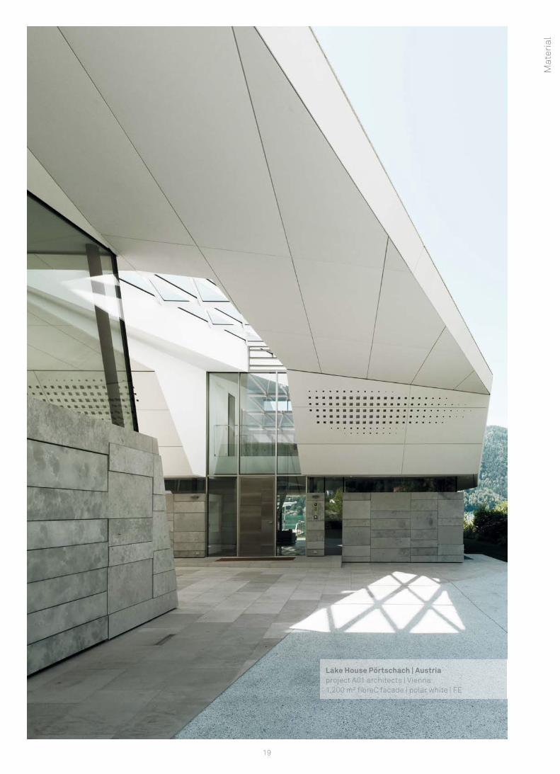
Lake House Pörtschach | Austriaproject A01 architects | Vienna1,200 m² fi breC facade | polar white | FE

20
Colours and surfaces Te
rra
Sand
ston
eSa
hara
Liqu
ide
Blac
kAn
thra
cite
Chro
me
Silv
ergr
ey
Ivor
yOf
f-W
hite
Pola
r Whi
teTe
rrac
otta
Gre
en
FE Ferro FL Ferro Light MA Matt
21
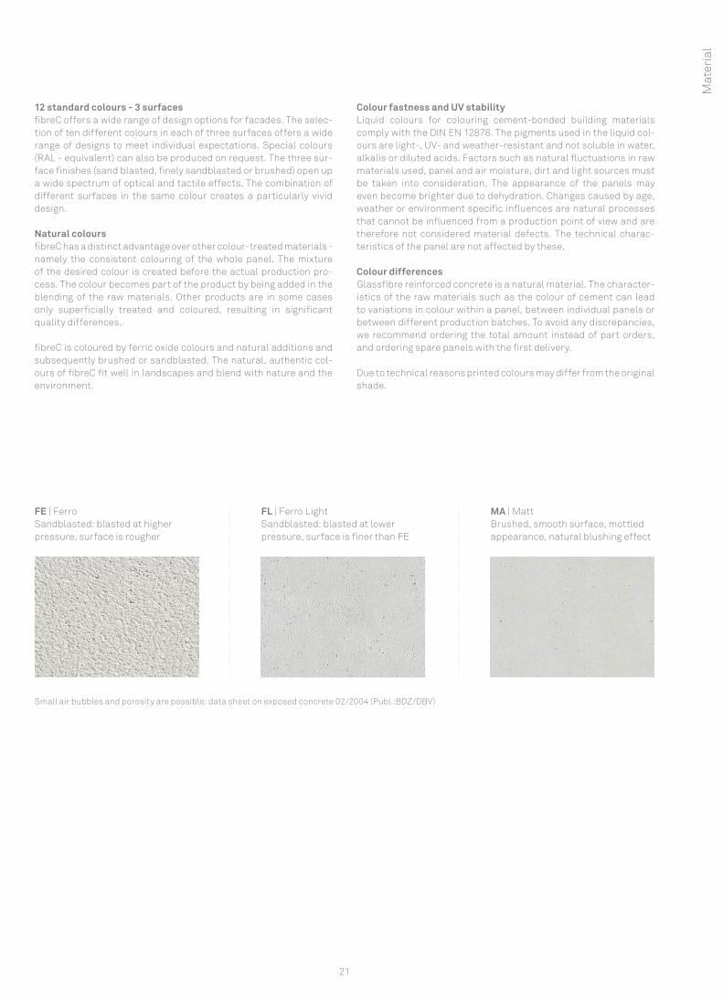
12 standard colours - 3 surfaces fibreC offers a wide range of design options for facades. The selec-tion of ten different colours in each of three surfaces offers a wide range of designs to meet individual expectations. Special colours (RAL - equivalent) can also be produced on request. The three sur-face finishes (sand blasted, finely sandblasted or brushed) open up a wide spectrum of optical and tactile effects. The combination of different surfaces in the same colour creates a particularly vivid design.
Natural colours fibreC has a distinct advantage over other colour-treated materials - namely the consistent colouring of the whole panel. The mixture of the desired colour is created before the actual production pro-cess. The colour becomes part of the product by being added in the blending of the raw materials. Other products are in some cases only superficially treated and coloured, resulting in significant quality differences.
fibreC is coloured by ferric oxide colours and natural additions and subsequently brushed or sandblasted. The natural, authentic col-ours of fibreC fit well in landscapes and blend with nature and the environment.
Colour fastness and UV stability Liquid colours for colouring cement-bonded building materials comply with the DIN EN 12878. The pigments used in the liquid col-ours are light-, UV- and weather-resistant and not soluble in water, alkalis or diluted acids. Factors such as natural fluctuations in raw materials used, panel and air moisture, dirt and light sources must be taken into consideration. The appearance of the panels may even become brighter due to dehydration. Changes caused by age, weather or environment specific influences are natural processes that cannot be influenced from a production point of view and are therefore not considered material defects. The technical charac-teristics of the panel are not affected by these.
Colour differences Glassfibre reinforced concrete is a natural material. The character-istics of the raw materials such as the colour of cement can lead to variations in colour within a panel, between individual panels or between different production batches. To avoid any discrepancies, we recommend ordering the total amount instead of part orders, and ordering spare panels with the first delivery.
Due to technical reasons printed colours may differ from the original shade.
Small air bubbles and porosity are possible: data sheet on exposed concrete 02/2004 (Publ.:BDZ/DBV)
FE | FerroSandblasted: blasted at higher pressure, surface is rougher
FL | Ferro LightSandblasted: blasted at lower pressure, surface is finer than FE
MA | Matt Brushed, smooth surface, mottled appearance, natural blushing effect
Mat
eria
l
22
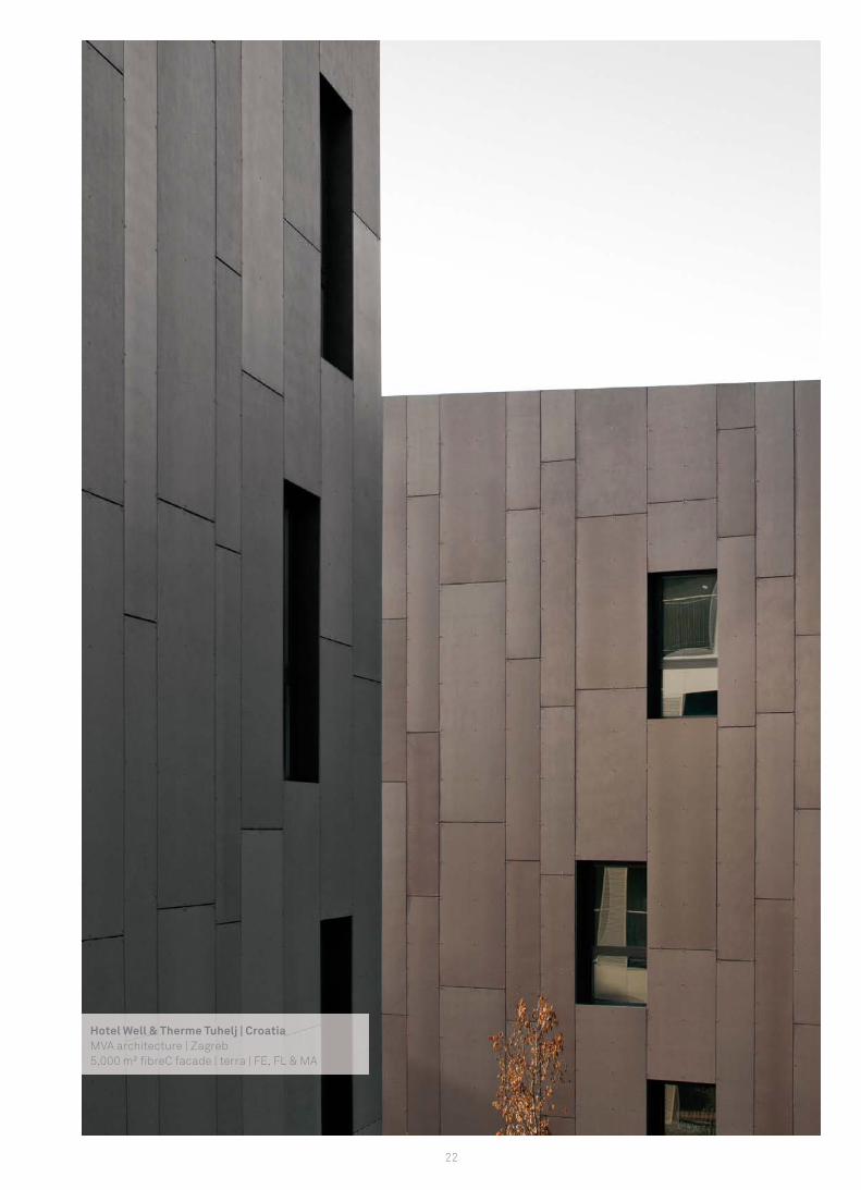
Hotel Well & Therme Tuhelj | CroatiaMVA architecture | Zagreb5,000 m² fi breC facade | terra | FE, FL & MA
10 mm
10 mm 10 mm
10 mm
23
Characteristics of fi breC
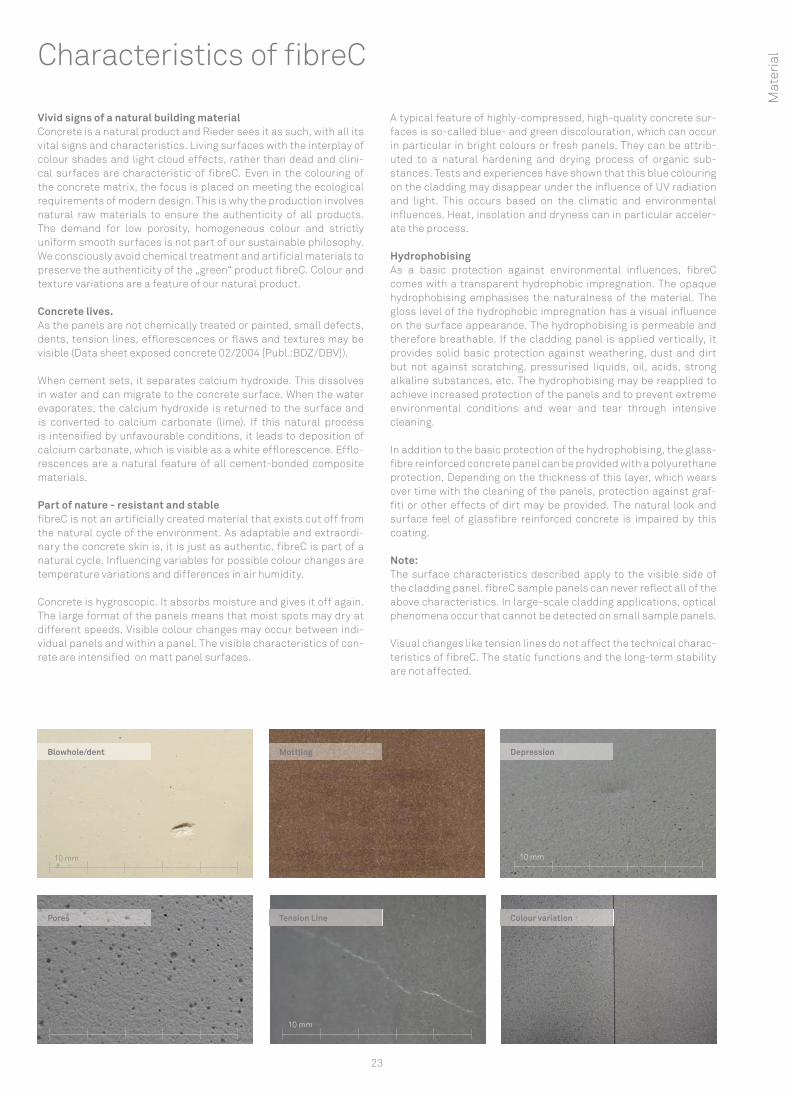
Vivid signs of a natural building material Concrete is a natural product and Rieder sees it as such, with all its vital signs and characteristics. Living surfaces with the interplay of colour shades and light cloud effects, rather than dead and clini-cal surfaces are characteristic of fi breC. Even in the colouring of the concrete matrix, the focus is placed on meeting the ecological requirements of modern design. This is why the production involves natural raw materials to ensure the authenticity of all products. The demand for low porosity, homogeneous colour and strictly uniform smooth surfaces is not part of our sustainable philosophy. We consciously avoid chemical treatment and artifi cial materials to preserve the authenticity of the „green“ product fi breC. Colour and texture variations are a feature of our natural product.
Concrete lives. As the panels are not chemically treated or painted, small defects, dents, tension lines, effl orescences or fl aws and textures may be visible (Data sheet exposed concrete 02/2004 [Publ.:BDZ/DBV]).
When cement sets, it separates calcium hydroxide. This dissolves in water and can migrate to the concrete surface. When the water evaporates, the calcium hydroxide is returned to the surface and is converted to calcium carbonate (lime). If this natural process is intensifi ed by unfavourable conditions, it leads to deposition of calcium carbonate, which is visible as a white effl orescence. Effl o-rescences are a natural feature of all cement-bonded composite materials.
Part of nature - resistant and stable fi breC is not an artifi cially created material that exists cut off from the natural cycle of the environment. As adaptable and extraordi-nary the concrete skin is, it is just as authentic. fi breC is part of a natural cycle. Infl uencing variables for possible colour changes are temperature variations and differences in air humidity.
Concrete is hygroscopic. It absorbs moisture and gives it off again. The large format of the panels means that moist spots may dry at different speeds. Visible colour changes may occur between indi-vidual panels and within a panel. The visible characteristics of con-rete are intensifi ed on matt panel surfaces.
A typical feature of highly-compressed, high-quality concrete sur-faces is so-called blue- and green discolouration, which can occur in particular in bright colours or fresh panels. They can be attrib-uted to a natural hardening and drying process of organic sub-stances. Tests and experiences have shown that this blue colouring on the cladding may disappear under the infl uence of UV radiation and light. This occurs based on the climatic and environmental infl uences. Heat, insolation and dryness can in particular acceler-ate the process.
Hydrophobising As a basic protection against environmental infl uences, fi breC comes with a transparent hydrophobic impregnation. The opaque hydrophobising emphasises the naturalness of the material. The gloss level of the hydrophobic impregnation has a visual infl uence on the surface appearance. The hydrophobising is permeable and therefore breathable. If the cladding panel is applied vertically, it provides solid basic protection against weathering, dust and dirt but not against scratching, pressurised liquids, oil, acids, strong alkaline substances, etc. The hydrophobising may be reapplied to achieve increased protection of the panels and to prevent extreme environmental conditions and wear and tear through intensive cleaning.
In addition to the basic protection of the hydrophobising, the glass-fi bre reinforced concrete panel can be provided with a polyurethane protection. Depending on the thickness of this layer, which wears over time with the cleaning of the panels, protection against graf-fi ti or other effects of dirt may be provided. The natural look and surface feel of glassfi bre reinforced concrete is impaired by this coating.
Note:The surface characteristics described apply to the visible side of the cladding panel. fi breC sample panels can never refl ect all of the above characteristics. In large-scale cladding applications, optical phenomena occur that cannot be detected on small sample panels.
Visual changes like tension lines do not affect the technical charac-teristics of fi breC. The static functions and the long-term stability are not affected.
Depression
Pores Tension Line Colour variation
MottlingBlowhole/dent
Mat
eria
l
24
Unlimited design possibilitiesIn the design of cladding, there are hardly no limits for planners and architects with fibreC. The selection of ten different colours in each of three surface forms the basis. In line with current trends and developments, fibreC offers a range of additional procedures for the creation of individual building shells.
fibreC offers a wide range of possibilities for printing the surface of the panel, irradiating designs, cutting out ornaments or lettering or incorporating a relief-like surface (e.g. a wood structure).
However what primarily characterises the material fibreC are the variations in the representation of shapes. With a specially devel-oped method, it is possible, to make glassfibre reinforced concrete flow around corners, or produce formed elements. Two-dimen-sional standard formed elements can be produced in real time. We would be delighted to meet you in person to tell you about triaxial curved elements.
· Perforation: Individual shapes or letters can be cut out of the panel using a water jet.
· Sandblasting: Using specially made jet films, patterns, charac-ters or logos can be applied permanently to the panel surface
· Digital or screen printing: fibreC panels can be printed using either digital or screen printing. Printing images, photographs, designs and texts are suitable for both outside and inside.
· Relief: Using a special technique, it is possible to produce relief-like rises on the fibreC panel.
· Formed elements: fibreC can be produced as U-shapes, arches, corners or other geometric shapes.
· Three-dimensional special shapes: Basically everything is possible. We have special projects where we work on solutions to cater for your individual requirements like special shapes or 2D and 3D formed elements.
Individualisation
Perforation
Base panel · panel size: max. 1200 x 3600 mm · surface: MA Matt, FL Ferro Light, FE Ferro · rear side: untreated
Perforation · perforation shape: round, oval or quadrangular, special shapes
on request · percentage of perforation: max. 30 % depending on statics · hole diameter: min. 80 mm (other diameters on request) · distance between holes: min. 80 mm or hole diameter · distance between holes and panel edge: min. 80 mm · in case of holes (rivet fixing) or undercut drillings additional
distance of 50 mm
Fastening · visible and invisible fastening systems · based on the results of the structural analyses, an additional
substructure resp. reinforcement may be required · review of statics is required
Handling · manual installation or vacuum suction of panels must be done
with special care
Please see the data sheet „fibreC Perforation“ for more information.
Sandblasting
Base panel · panel size: max. 1200 x 3600 mm · surface: basic panel MA Matt · colour: possible with all colours (effect depending on colour) · rear side: untreated
Blasting · logos and images can be negatively or positively blasted · positive: lettering or image is matt · negative: lettering or image is sandblasted · contour thickness > 5 mm
Data Depending on the design, the data should be provided as an eps, dxf or dwg file. Where there are depictions or designs crossing over several panels, it is the customer’s responsibility to ensure that the logo runs from panel to panel taking the joint into con-sideration. A separate graphic file must be created for each panel.
Handling · Panel fastening: manual or with suction pad · Handling the panel with particular care
25
Base panel · panel size depends on printhouse/printing machine · surface: MA Matt · rear side: untreated
Internal application · digital print, print resolution min. 720 dpi · individual print possible from one unit · bright panel colour is recommended as print base · can be combined with screen printing or radiation
External application · screen printing · metallic colours possible · highly lit 2K screen printing colours · halftone images · very long durability
Handling · panel fastening: manual or with suction pad · handling the panel with particular care
Digital or screen printing
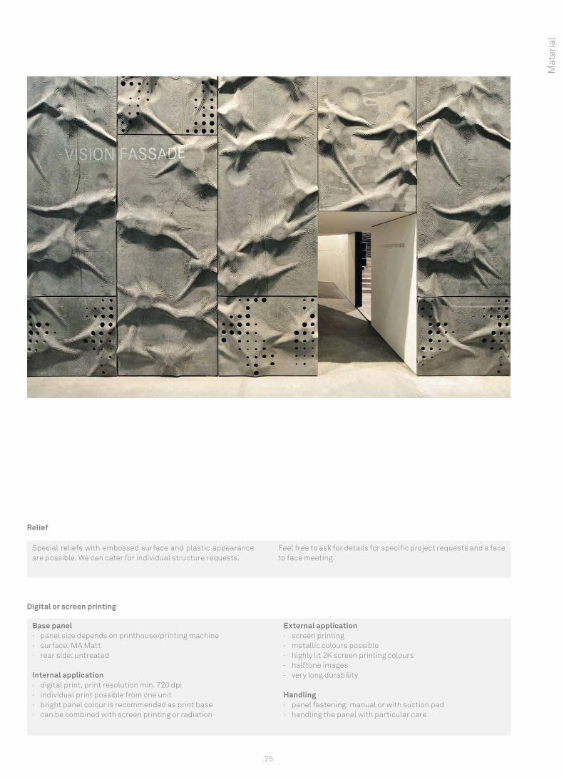
Special reliefs with embossed surface and plastic appearance are possible. We can cater for individual structure requests.
Feel free to ask for details for specific project requests and a face to face meeting.
Relief
Mat
eria
l
26
Special cuts
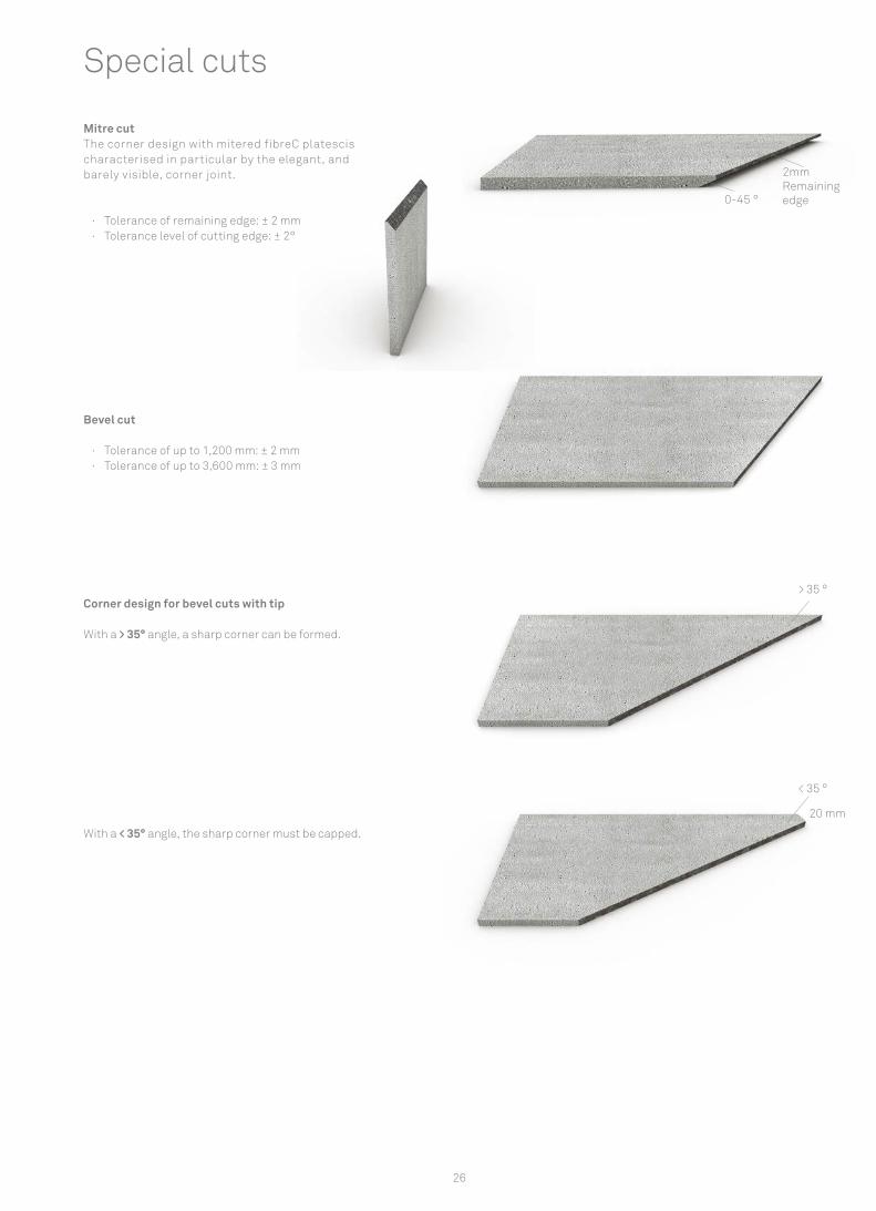
Mitre cutThe corner design with mitered fibreC platescis characterised in particular by the elegant, and barely visible, corner joint.
· Tolerance of remaining edge: ± 2 mm · Tolerance level of cutting edge: ± 2°
Bevel cut
· Tolerance of up to 1,200 mm: ± 2 mm · Tolerance of up to 3,600 mm: ± 3 mm
Corner design for bevel cuts with tip
With a > 35° angle, a sharp corner can be formed.
With a < 35° angle, the sharp corner must be capped.
20 mm
> 35 °
< 35 °
2mm Remaining edge0-45 °
27
Mat
eria
l
2mm Remaining edge
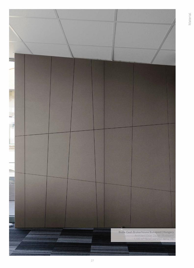
Buda-Cash Brokerhouse Budapest | HungaryArchitect Ekler Dezsö | Budapest
1,100 m² fi breC panels | terra | FE
28
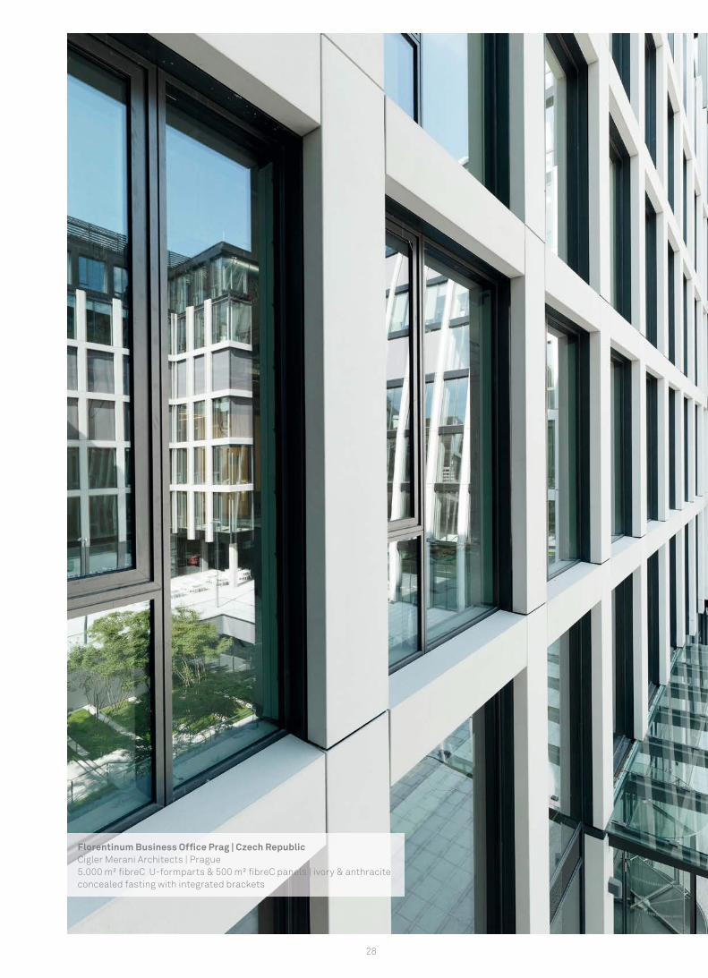
Florentinum Business Offi ce Prag | Czech RepublicCigler Merani Architects | Prague5.000 m² fi breC U-formparts & 500 m² fi breC panels | ivory & anthraciteconcealed fasting with integrated brackets

29
Form
part
s &
fins
fibreC formparts and fibreC fins ..........................................................................................................................................................................30 Product description fibreC formparts..................................................................................................................................................................32Product description fibreC fins ............................................................................................................................................................................32Fastening fibreC formparts...................................................................................................................................................................................33Fastening fibreC fins...............................................................................................................................................................................................34
70 mm
70 mm70 mm
3.600 mm
1.800 mm
fibreC fins
30
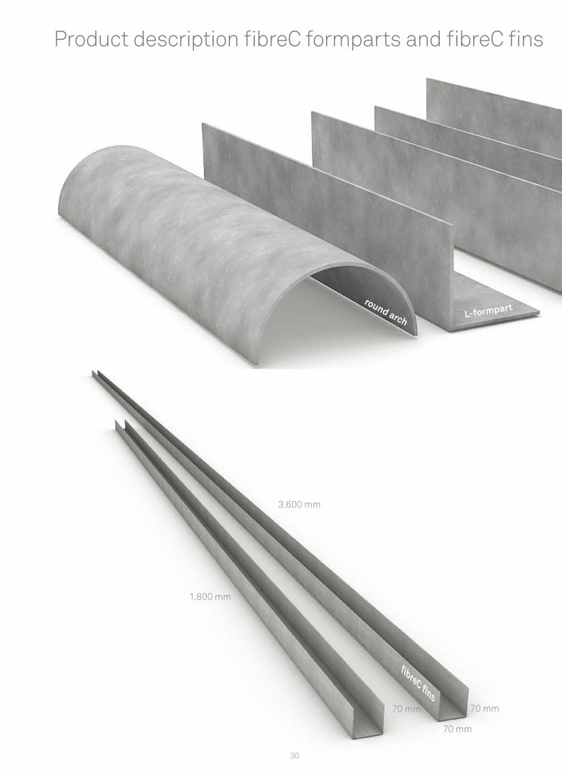
Product description fibreC formparts and fibreC fins
L-formpartround arch
31
Form
part
s &
fins
Product description fibreC formparts and fibreC fins
fibreC fins are mould elements with U-shaped cross-section in 70 x 70 mm format. fibreC fins are available in 12 colours, 2 surfaces apiece. fibreC fins are popularly used as lean concrete slats for facades, for the purpose of providing large window areas with per-manent sun protection or providing the building casing with creative design elements. The geometric shape of the fibreC fins allows for special light effects in interiors when there is daylight outside.
Section: 70 x 70 x 70 mmLength: 1,800 mm | 3,600 mmPanel thickness: 13 mm
More square, right angle or circular cross sections available on request.
Mounting options: · Visible: rivet · Not visible: bonding · Customised factory attachment solution:
on request (see page 34)
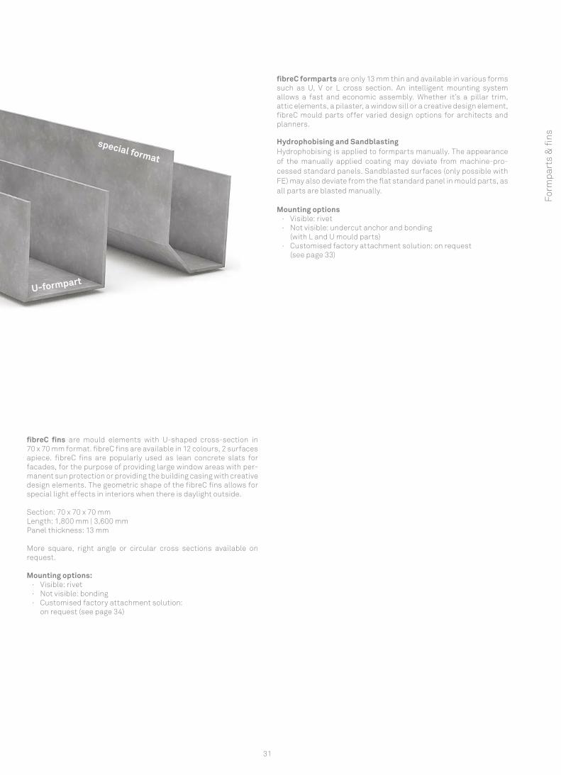
fibreC formparts are only 13 mm thin and available in various formssuch as U, V or L cross section. An intelligent mounting system allows a fast and economic assembly. Whether it’s a pillar trim, attic elements, a pilaster, a window sill or a creative design element, fibreC mould parts offer varied design options for architects and planners.
Hydrophobising and SandblastingHydrophobising is applied to formparts manually. The appearance of the manually applied coating may deviate from machine-pro-cessed standard panels. Sandblasted surfaces (only possible with FE) may also deviate from the flat standard panel in mould parts, as all parts are blasted manually.
Mounting options · Visible: rivet · Not visible: undercut anchor and bonding
(with L and U mould parts) · Customised factory attachment solution: on request
(see page 33)
U-formpart
special format
U1
U2
U3
L
L1
L2
L
S1
S2
S3
S4
L
L
32
radius R
arc lengthB
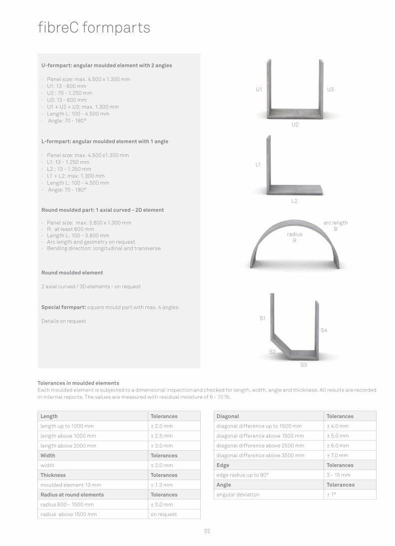
Tolerances in moulded elementsEach moulded element is subjected to a dimensional inspection and checked for length, width, angle and thickness. All results are recorded in internal reports. The values are measured with residual moisture of 6 - 10 %.
fibreC formparts
U-formpart: angular moulded element with 2 angles
· Panel size: max. 4.500 x 1.300 mm · U1: 13 - 600 mm · U2 : 70 - 1.250 mm · U3: 13 - 600 mm · U1 + U2 + U3: max. 1.300 mm · Length L: 100 - 4.500 mm · Angle: 70 - 180°
L-formpart: angular moulded element with 1 angle
· Panel size: max. 4.500 x1.300 mm · L1: 13 - 1.250 mm · L2 : 13 - 1.250 mm · L1 + L2: max. 1.300 mm · Length L: 100 - 4.500 mm · Angle: 70 - 180°
Round moulded part: 1 axial curved - 2D element
· Panel size: max. 3.800 x 1.300 mm · R: at least 600 mm · Length L: 100 - 3.800 mm · Arc length and geometry on request · Bending direction: longitudinal and transverse
Round moulded element
2 axial curved / 3D elements - on request
Special formpart: square mould part with max. 4 angles
Details on request
Length Tolerances
length up to 1000 mm ± 2.0 mm
length above 1000 mm ± 2.5 mm
length above 2000 mm ± 3.0 mm
Width Tolerances
width ± 2.0 mm
Thickness Tolerances
moulded element 13 mm ± 1.3 mm
Radius at round elements Tolerances
radius 600 - 1500 mm ± 3.0 mm
radius above 1500 mm on request
Diagonal Tolerances
diagonal difference up to 1500 mm ± 4.0 mm
diagonal difference above 1500 mm ± 5.0 mm
diagonal difference above 2500 mm ± 6.0 mm
diagonal difference above 3500 mm ± 7.0 mm
Edge Tolerances
edge radius up to 90° 3 - 15 mm
Angle Tolerances
angular deviation ± 1°
33
Form
part
s &
fins
Fastening fibreC formparts
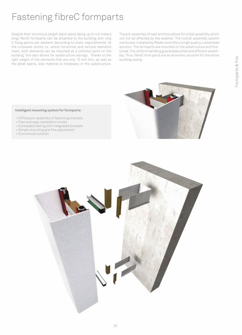
Despite their enormous length (each piece being up to 4.5 meters long) fibreC formparts can be attached to the building with only 2 fixing points per element (according to static requirements). At the crossover points i.e. where horizontal and vertical elements meet, both elements can be mounted at a common point on the building; this also allows for substructure savings. Thanks to the light weight of the elements that are only 13 mm thin, as well as the great spans, less material is necessary in the substructure.
The pre-assembly of wall anchors allows for a fast assembly which will not be affected by the weather. The overall assembly system can be pre-installed by Rieder and offers a high quality customised solution. The formparts are mounted on the substructure and fine-tuned. The uniform handling guarantees a fast and efficient assem-bly. Thus, fibreC form parts are an economic solution for the entire building casing
Intelligent mounting system for formparts:
• Offsite pre-assembly of fastening brackets• Fast and easy installation onsite• Concealed fasting with integrated brackets• Simple mounting and fine adjustment • Economical solution
1 2 3
U1
U2
U3
L
34
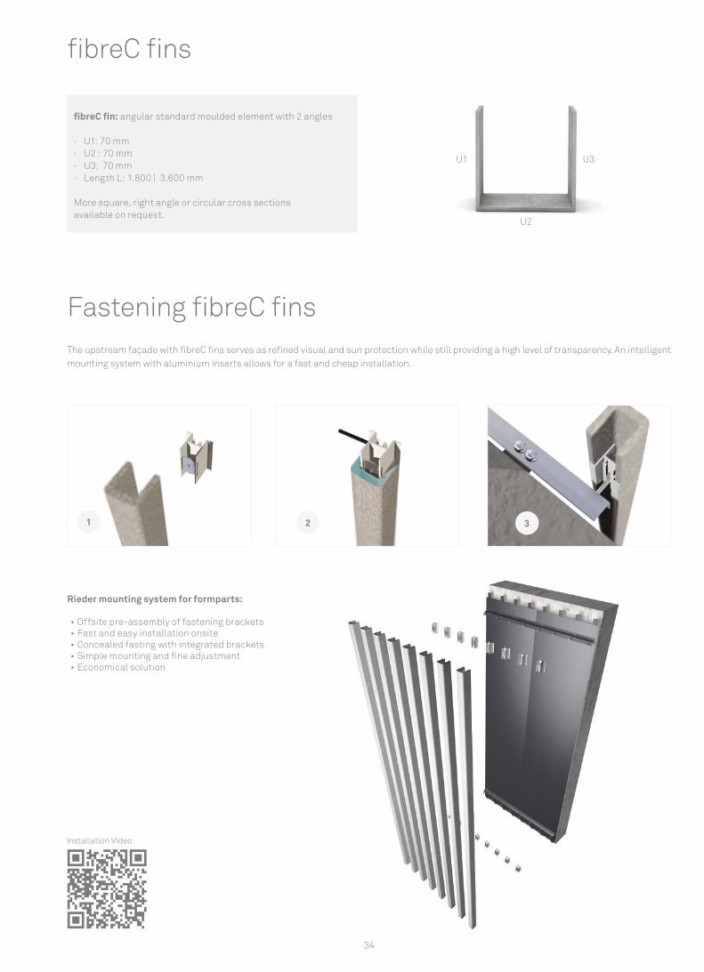
The upstream façade with fibreC fins serves as refined visual and sun protection while still providing a high level of transparency. An intelligent mounting system with aluminium inserts allows for a fast and cheap installation.
Fastening fibreC fins
fibreC fins
fibreC fin: angular standard moulded element with 2 angles
· U1: 70 mm · U2 : 70 mm · U3: 70 mm · Length L: 1.800 | 3.600 mm
More square, right angle or circular cross sections available on request.
Rieder mounting system for formparts:
• Offsite pre-assembly of fastening brackets• Fast and easy installation onsite• Concealed fasting with integrated brackets• Simple mounting and fine adjustment • Economical solution
Installation Video
35
Form
part
s &
fi ns
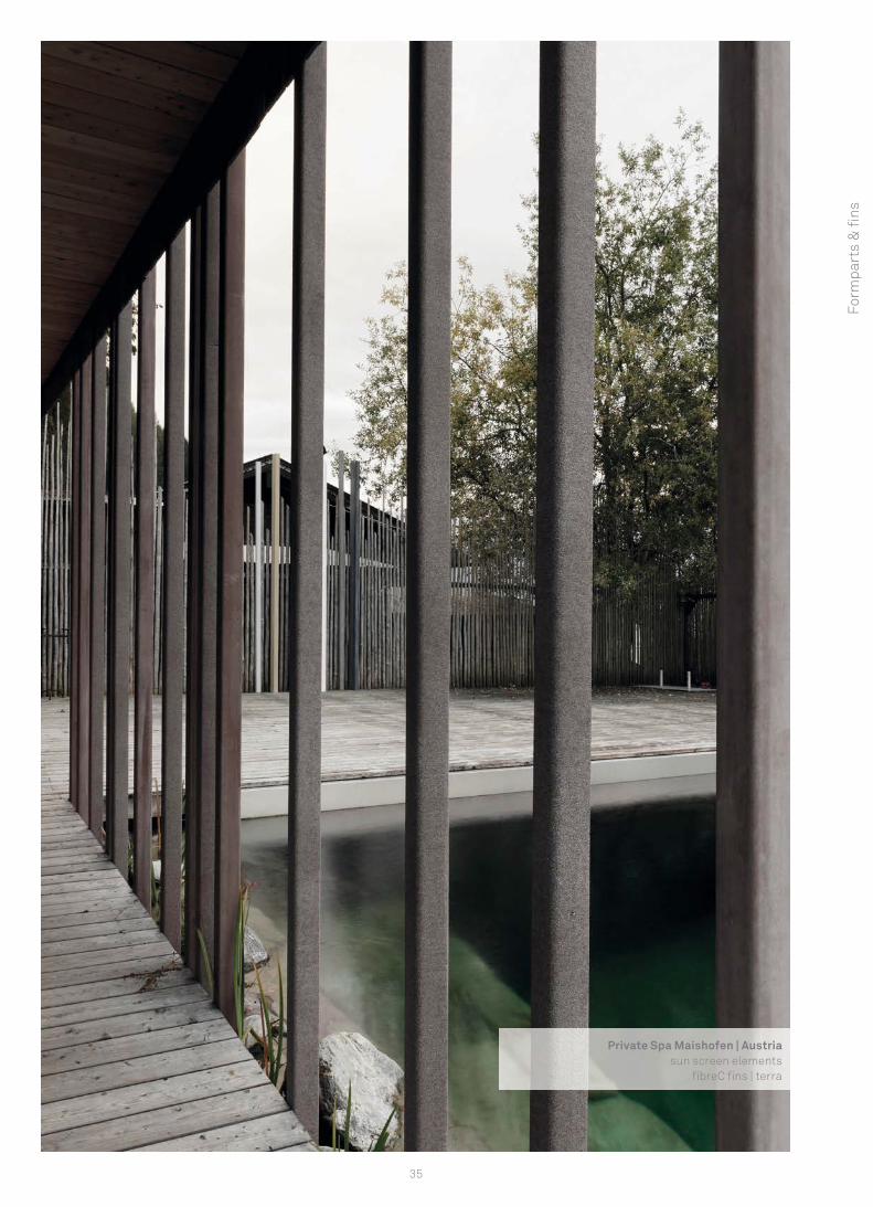
Private Spa Maishofen | Austriasun screen elements
fi breC fi ns | terra

36
City hall Hannover - Linden | GermanyWoelk Wilkens Architects | Hannover360 m² fi breC facade | ivory | FL

37
Cla
ddin
g sy
stemCladding system
Ventilated rainscreen cladding.............................................................................................................................................................................38Corner solutions ......................................................................................................................................................................................................40Joints........................................................................................................................................................................................................................41Laying direction .......................................................................................................................................................................................................41
38
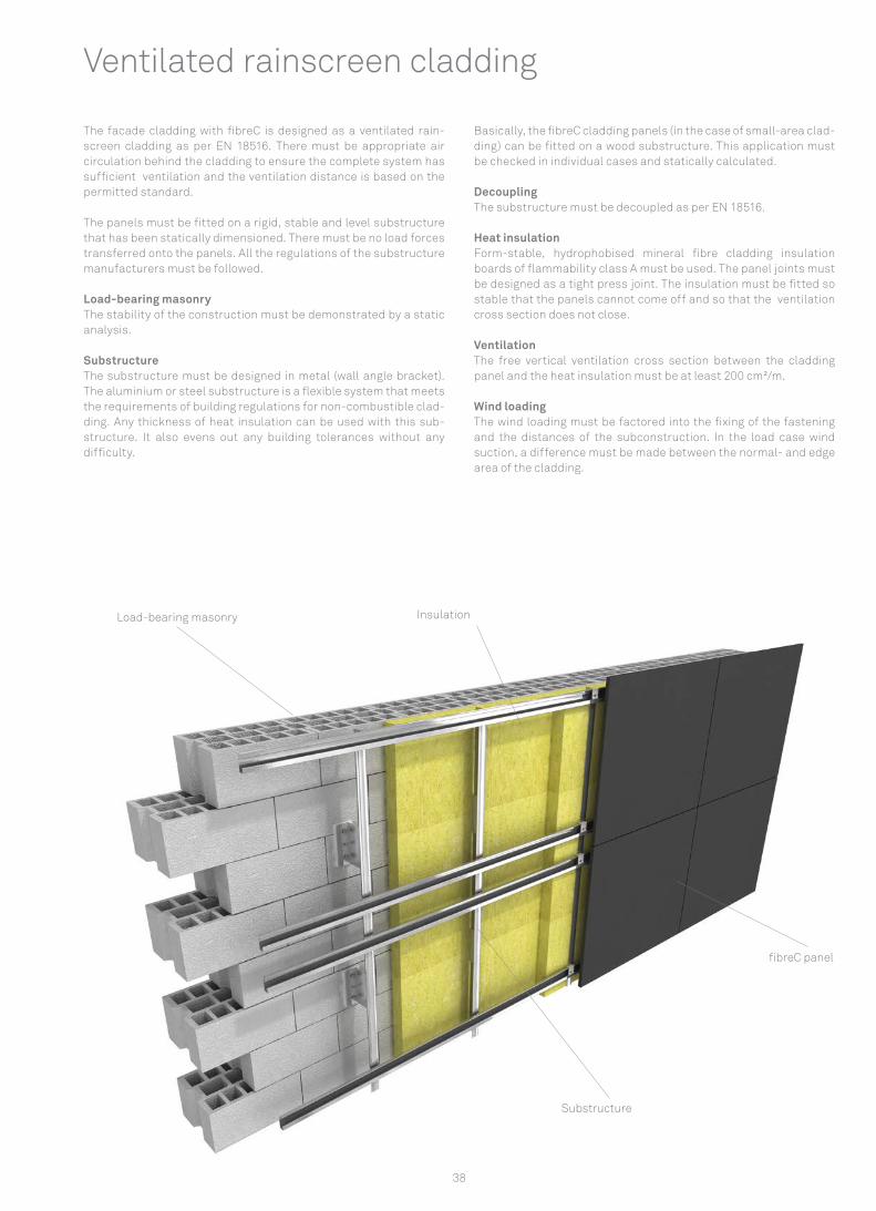
Ventilated rainscreen cladding
The facade cladding with fibreC is designed as a ventilated rain-screen cladding as per EN 18516. There must be appropriate air circulation behind the cladding to ensure the complete system has sufficient ventilation and the ventilation distance is based on the permitted standard.
The panels must be fitted on a rigid, stable and level substructure that has been statically dimensioned. There must be no load forces transferred onto the panels. All the regulations of the substructure manufacturers must be followed.
Load-bearing masonry The stability of the construction must be demonstrated by a static analysis.
Substructure The substructure must be designed in metal (wall angle bracket). The aluminium or steel substructure is a flexible system that meets the requirements of building regulations for non-combustible clad-ding. Any thickness of heat insulation can be used with this sub-structure. It also evens out any building tolerances without any difficulty.
Basically, the fibreC cladding panels (in the case of small-area clad-ding) can be fitted on a wood substructure. This application must be checked in individual cases and statically calculated.
Decoupling The substructure must be decoupled as per EN 18516.
Heat insulation Form-stable, hydrophobised mineral fibre cladding insulation boards of flammability class A must be used. The panel joints must be designed as a tight press joint. The insulation must be fitted so stable that the panels cannot come off and so that the ventilation cross section does not close.
Ventilation The free vertical ventilation cross section between the cladding panel and the heat insulation must be at least 200 cm²/m.
Wind loading The wind loading must be factored into the fixing of the fastening and the distances of the subconstruction. In the load case wind suction, a difference must be made between the normal- and edge area of the cladding.
Load-bearing masonry Insulation
fibreC panel
Substructure
1
4
8 6
7
5
3
2
39
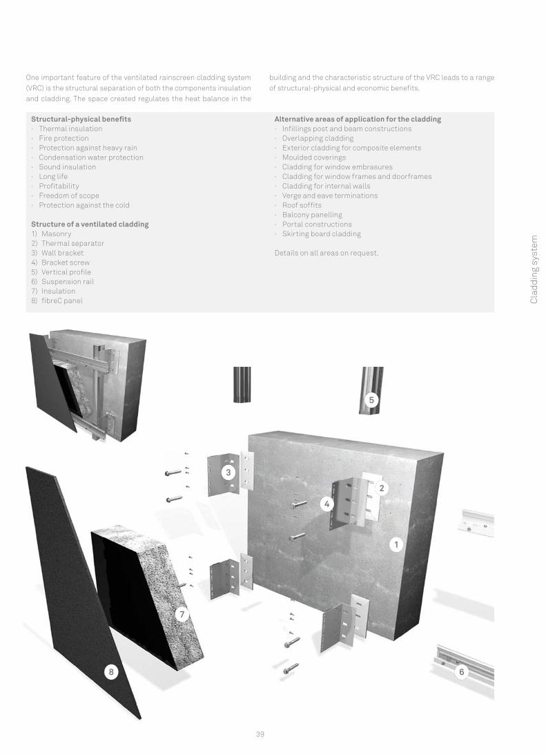
Structural-physical benefits · Thermal insulation · Fire protection · Protection against heavy rain · Condensation water protection · Sound insulation · Long life · Profitability · Freedom of scope · Protection against the cold
Structure of a ventilated cladding 1) Masonry 2) Thermal separator 3) Wall bracket 4) Bracket screw 5) Vertical profile 6) Suspension rail 7) Insulation 8) fibreC panel
Alternative areas of application for the cladding · Infillings post and beam constructions · Overlapping cladding · Exterior cladding for composite elements · Moulded coverings · Cladding for window embrasures · Cladding for window frames and doorframes · Cladding for internal walls · Verge and eave terminations · Roof soffits · Balcony panelling · Portal constructions · Skirting board cladding
Details on all areas on request.
One important feature of the ventilated rainscreen cladding system (VRC) is the structural separation of both the components insulation and cladding. The space created regulates the heat balance in the
building and the characteristic structure of the VRC leads to a range of structural-physical and economic benefits.
Cla
ddin
g sy
stem
40
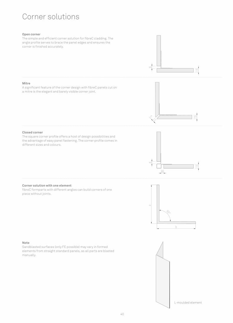
Open corner The simple and effi cient corner solution for fi breC cladding. The angle profi le serves to brace the panel edges and ensures the corner is fi nished accurately.
Mitre A signifi cant feature of the corner design with fi breC panels cut on a mitre is the elegant and barely visible corner joint.
Closed corner The square corner profi le offers a host of design possibilities and the advantage of easy panel fastening. The corner profi le comes in different sizes and colours.
Corner solution with one element fi breC formparts with different angles can build corners of one piece without joints.
NoteSandblasted surfaces (only FE possible) may vary in formed elements from straight standard panels, as all parts are blasted manually.
Corner solutions
L-moulded element

41
Open joint Panel connections with an open joint do not impair the consistent homogeneous image of the cladding.
Joint width: min. 8 mm
Closed joint The joints are closed using joint profi les that can be designed in different colours and dimensions.
Joint width: min. 8 mm
Joints
Laying directionThe installation directions must be followed to ensure a uniform cladding appearance. The general processing information and installation instructions for fi breC apply.
Cla
ddin
g sy
stem
42
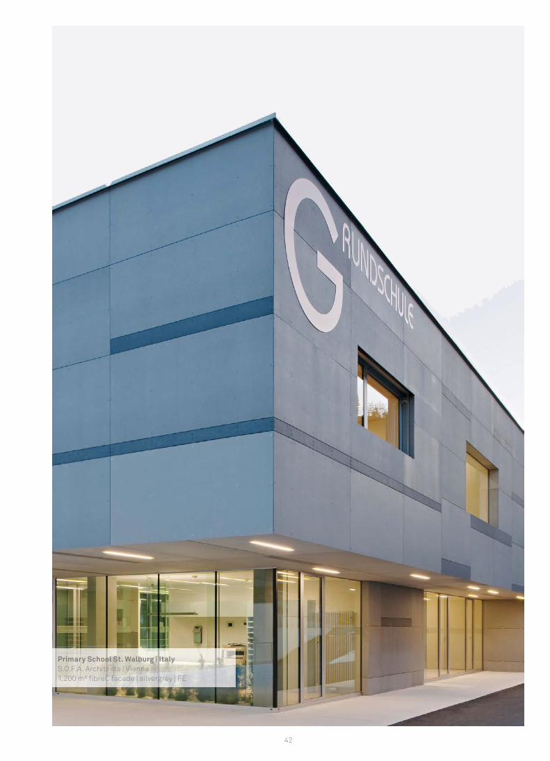
Primary School St. Walburg | ItalyS.O.F.A. Architects | Vienna 1,200 m² fi breC facade | silvergrey | FE

43
Types of fasteningOverview of fastening types..................................................................................................................................................................................44Undercut..................................................................................................................................................................................................46Rivets...........................................................................................................................................................................................................52Adhesive..........................................................................................................................................................................................................................58
Fast
enin
g
44
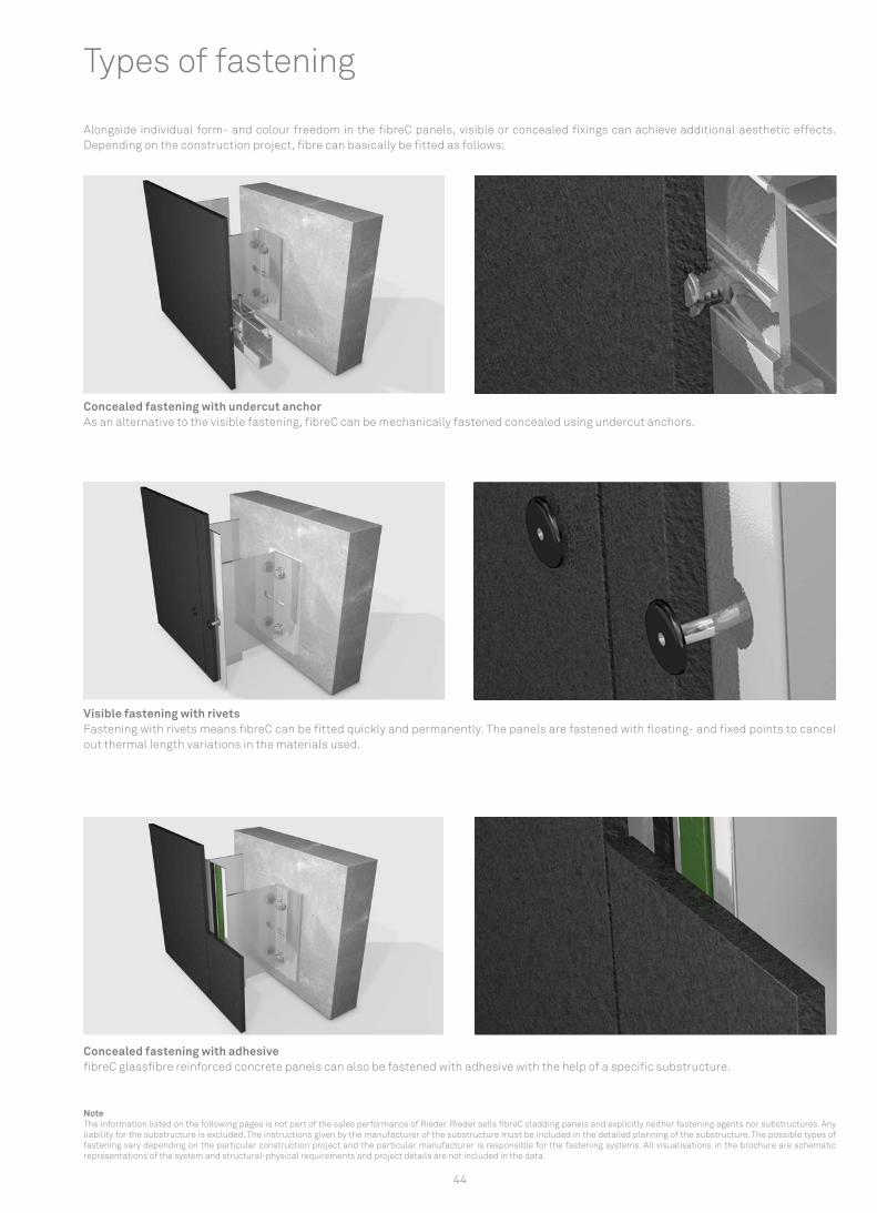
Concealed fastening with undercut anchor As an alternative to the visible fastening, fibreC can be mechanically fastened concealed using undercut anchors.
Visible fastening with rivets Fastening with rivets means fibreC can be fitted quickly and permanently. The panels are fastened with floating- and fixed points to cancel out thermal length variations in the materials used.
Concealed fastening with adhesive fibreC glassfibre reinforced concrete panels can also be fastened with adhesive with the help of a specific substructure.
Types of fastening
Alongside individual form- and colour freedom in the fibreC panels, visible or concealed fixings can achieve additional aesthetic effects. Depending on the construction project, fibre can basically be fitted as follows:
NoteThe information listed on the following pages is not part of the sales performance of Rieder. Rieder sells fibreC cladding panels and explicitly neither fastening agents nor substructures. Any liability for the substructure is excluded. The instructions given by the manufacturer of the substructure must be included in the detailed planning of the substructure. The possible types of fastening vary depending on the particular construction project and the particular manufacturer is responsible for the fastening systems. All visualisations in the brochure are schematic representations of the system and structural-physical requirements and project details are not included in the data.
45
Fast
enin
g
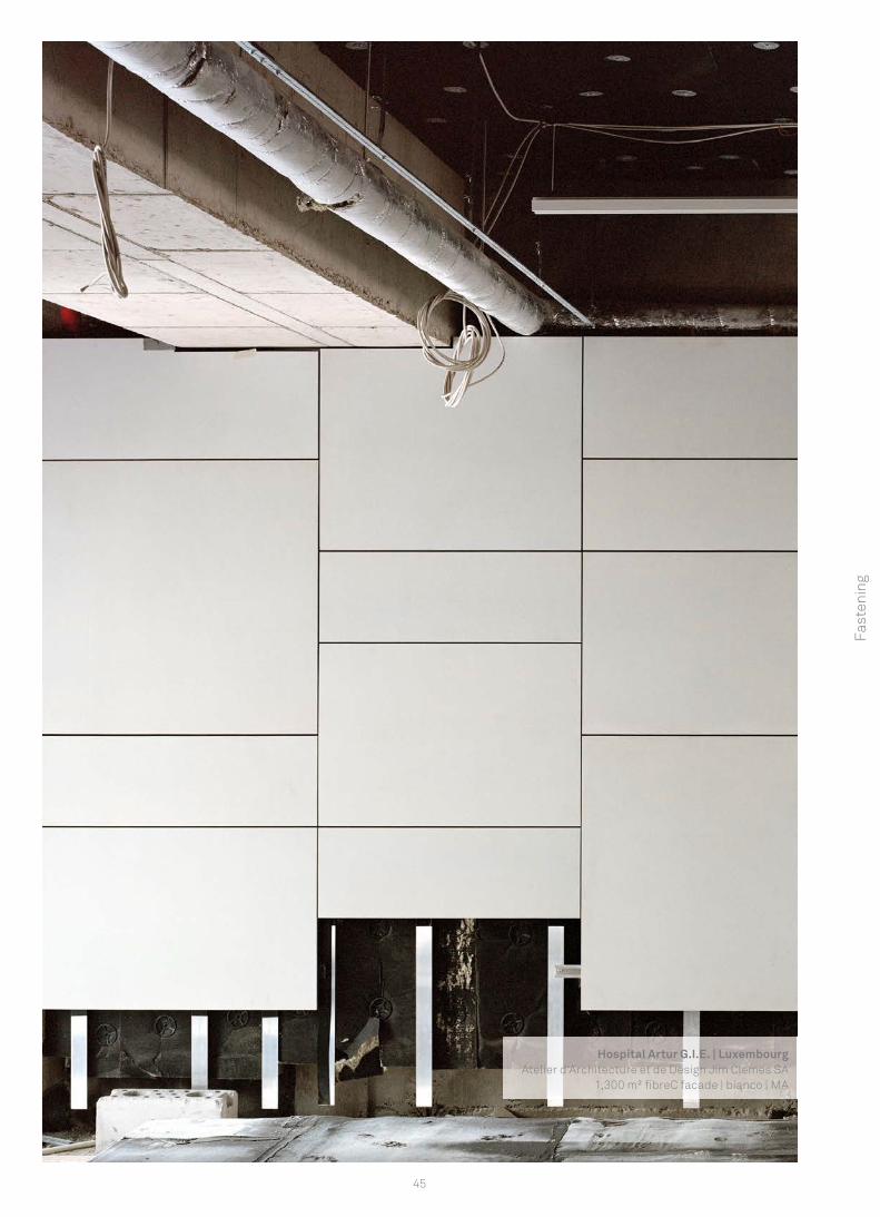
Hospital Artur G.I.E. | LuxembourgAtelier d‘Architecture et de Design Jim Clemes SA
1,300 m² fi breC facade | bianco | MA

8
1
4
8
6
7
5
3
2
9
46
Panels with a thickness of 13 mm can be fitted invisible on the back with metal clips and special dowels. For this purpose, each panel has on the top row of clips adjusting screws and a fixed point fastening (screw or clip), with the result that it can be aligned and no displacement occurs. The maximum construction height is 100 m. Additional heights must be checked with a special approval by the customer.
Invisible fastening with undercut anchor
Structure1) Masonry 2) Thermal separator 3) Wall bracket 4) Bracket screw 5) Vertical profile 6) Suspension rail 7) Clip 8) Undercut screw and anchor 9) fibreC panel
47
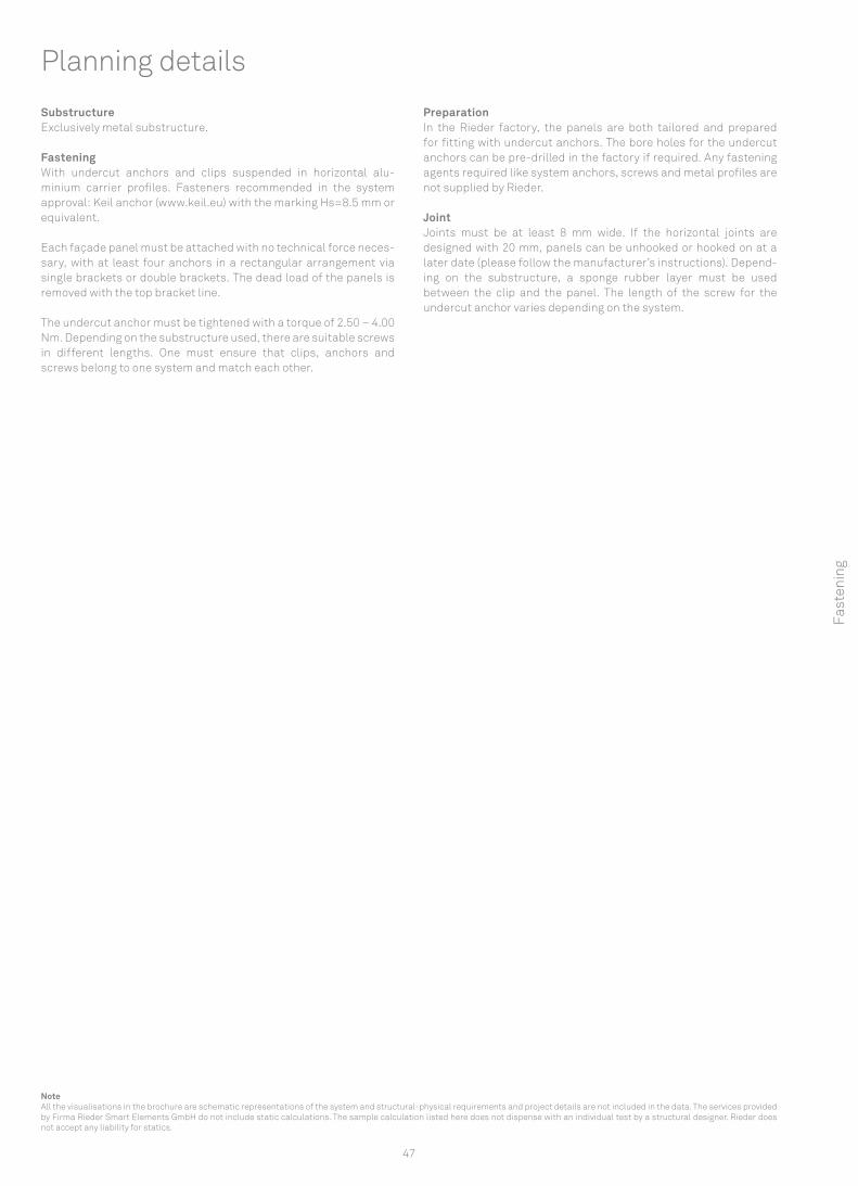
Substructure Exclusively metal substructure.
Fastening With undercut anchors and clips suspended in horizontal alu-minium carrier profiles. Fasteners recommended in the system approval: Keil anchor (www.keil.eu) with the marking Hs=8.5 mm or equivalent.
Each façade panel must be attached with no technical force neces-sary, with at least four anchors in a rectangular arrangement via single brackets or double brackets. The dead load of the panels is removed with the top bracket line.
The undercut anchor must be tightened with a torque of 2.50 – 4.00 Nm. Depending on the substructure used, there are suitable screws in different lengths. One must ensure that clips, anchors and screws belong to one system and match each other.
Preparation In the Rieder factory, the panels are both tailored and prepared for fitting with undercut anchors. The bore holes for the undercut anchors can be pre-drilled in the factory if required. Any fastening agents required like system anchors, screws and metal profiles are not supplied by Rieder.
JointJoints must be at least 8 mm wide. If the horizontal joints are designed with 20 mm, panels can be unhooked or hooked on at a later date (please follow the manufacturer’s instructions). Depend-ing on the substructure, a sponge rubber layer must be used between the clip and the panel. The length of the screw for the undercut anchor varies depending on the system.
Planning details
NoteAll the visualisations in the brochure are schematic representations of the system and structural-physical requirements and project details are not included in the data. The services provided by Firma Rieder Smart Elements GmbH do not include static calculations. The sample calculation listed here does not dispense with an individual test by a structural designer. Rieder does not accept any liability for statics.
Fast
enin
g
6-10 x 6-10
L
B
6-10
6-10
Y
6-10 6-10
B
L
6-10
6-10
YY
x x6-10 6-10
B
L
6-10
6-10
YY
x
48
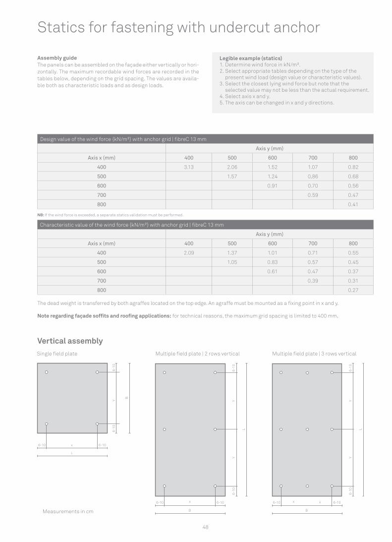
Design value of the wind force {kN/m²} with anchor grid | fibreC 13 mm
Axis y (mm)
Axis x (mm) 400 500 600 700 800
400 3.13 2.06 1.52 1.07 0.82
500 1.57 1.24 0,86 0.68
600 0.91 0.70 0.56
700 0.59 0.47
800 0.41
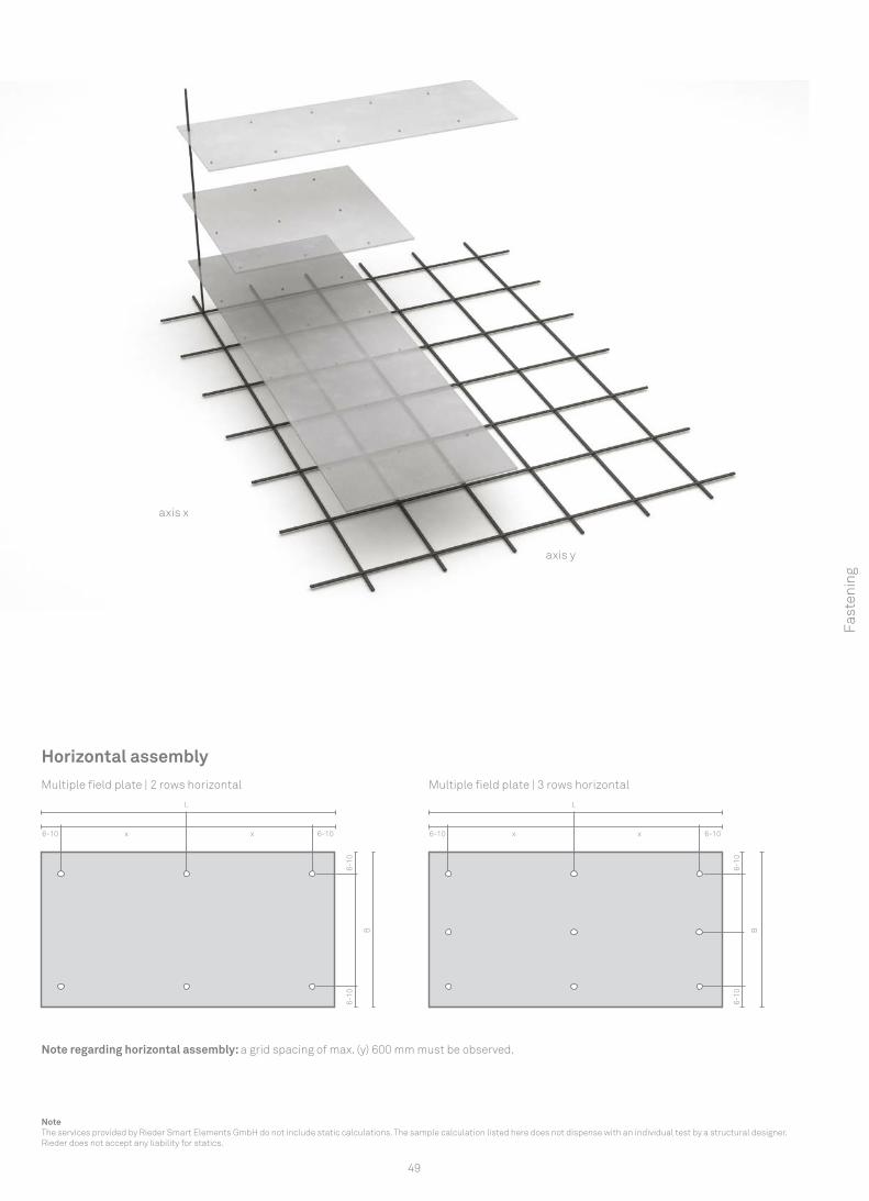
Assembly guideThe panels can be assembled on the façade either vertically or hori-zontally. The maximum recordable wind forces are recorded in the tables below, depending on the grid spacing. The values are availa-ble both as characteristic loads and as design loads.
Vertical assembly
NB: If the wind force is exceeded, a separate statics validation must be performed.
Single field plate Multiple field plate | 2 rows vertical Multiple field plate | 3 rows vertical
Measurements in cm
Characteristic value of the wind force {kN/m²} with anchor grid | fibreC 13 mm
Axis y (mm)
Axis x (mm) 400 500 600 700 800
400 2.09 1.37 1.01 0.71 0.55
500 1.05 0.83 0.57 0.45
600 0.61 0.47 0.37
700 0.39 0.31
800 0.27
Legible example (statics)1. Determine wind force in kN/m².2. Select appropriate tables depending on the type of the
present wind load (design value or characteristic values).3. Select the closest lying wind force but note that the
selected value may not be less than the actual requirement.4. Select axis x and y.5. The axis can be changed in x and y directions.
The dead weight is transferred by both agraffes located on the top edge. An agraffe must be mounted as a fixing point in x and y.
Note regarding façade soffits and roofing applications: for technical reasons, the maximum grid spacing is limited to 400 mm.
Statics for fastening with undercut anchor
6-10
6-10
B
6-10 6-10x x
L
6-10
6-10
B
6-10 6-10x x
L
49
NoteThe services provided by Rieder Smart Elements GmbH do not include static calculations. The sample calculation listed here does not dispense with an individual test by a structural designer. Rieder does not accept any liability for statics.
Fast
enin
g
Horizontal assemblyMultiple field plate | 2 rows horizontal Multiple field plate | 3 rows horizontal
Note regarding horizontal assembly: a grid spacing of max. (y) 600 mm must be observed.
axis x
axis y
50
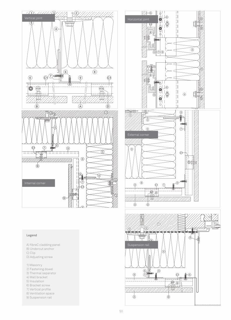
Suspension rail
External corner
Horizontal joint Vertical joint
Internal corner
Legend
A) fibreC cladding panel B) Undercut anchor C) Clip D) Adjusting screw
1) Masonry 2) Fastening dowel 3) Thermal separator 4) Wall bracket5) Insulation 6) Bracket screw 7) Vertical profile 8) Ventilation space 9) Suspension rail
51
Fast
enin
g
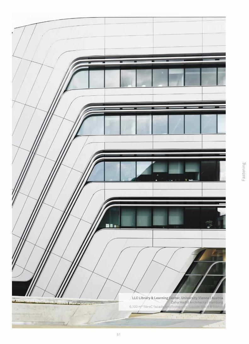
LLC Library & Learning Center, University Vienna | AustriaZaha Hadid Architects | Hamburg
6,100 m² fi breC facade and formparts | liquide black & bianco
6
1
4
67
5
3
2
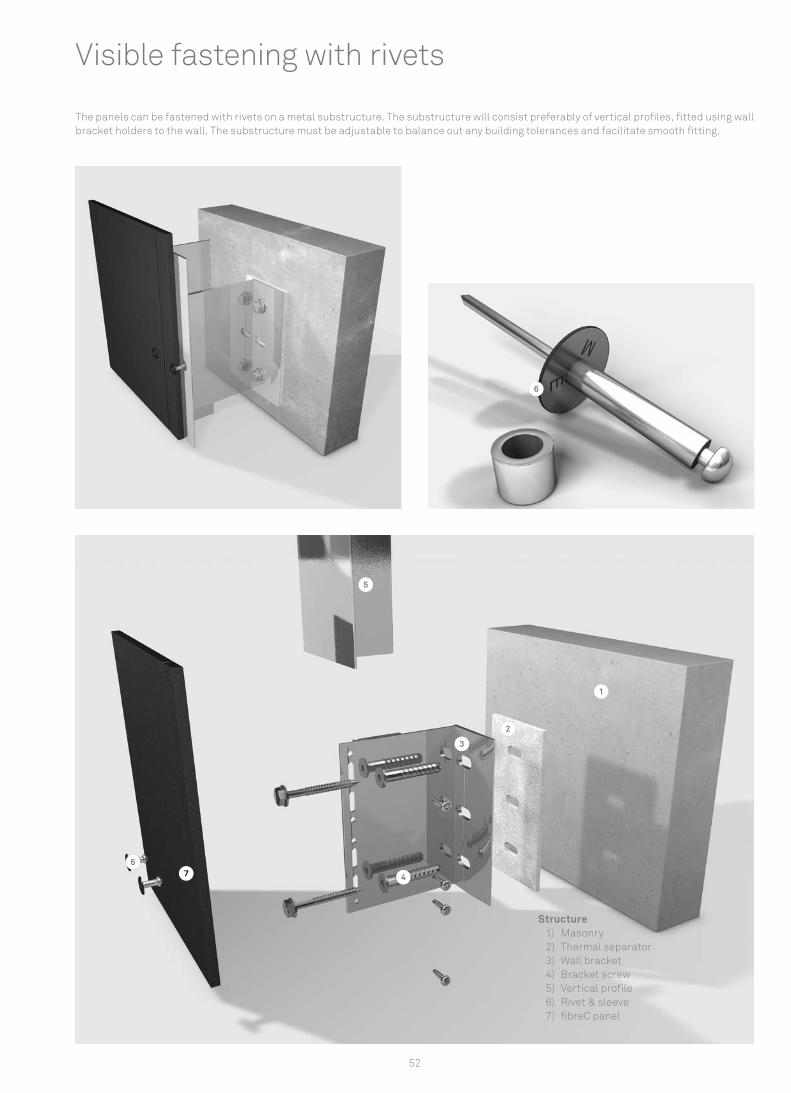
52
The panels can be fastened with rivets on a metal substructure. The substructure will consist preferably of vertical profiles, fitted using wall bracket holders to the wall. The substructure must be adjustable to balance out any building tolerances and facilitate smooth fitting.
Visible fastening with rivets
Structure1) Masonry 2) Thermal separator 3) Wall bracket 4) Bracket screw 5) Vertical profile6) Rivet & sleeve 7) fibreC panel
53
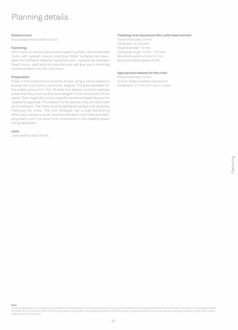
Substructure Exclusively metal substructure.
Fastening With rivets on vertical aluminium support profiles. Recommended rivets with special colours matching fibreC surfaces are avail-able from different fastener manufacturers. Indicate the standard fibreC colour used and the manufacturer will give you a matching recommendation for the rivet colour.
Preparation Holes in the substructure must be drilled using a centre sleeve to ensure the bore hole is centrically aligned. The bore diameter for the substructure is 5.1 mm. At least two sleeves must be used per panel and they must usually be arranged in the centre point of the panel. There might be country-specific variations depending on the respective approval. The sleeves fix the panels; they are described as a fixed point. The rivets must be tightened using a rivet template matching the rivets. The rivet template has a load-distributing effect and creates a small clearance between rivet head and clad-ding board, with the result that movements in the cladding board can be absorbed.
Joint Joint width at least 8 mm.
Cladding rivet aluminium/Niro with head varnish: Panel thickness 13 mm Dimension: 5 x 23 mm Head diameter: 14 mm Clamping range: 14.00 – 17.5 mm Bore hole substructure: 5.1 mm Bore hole fibreC panel: 8 mm
Appropriate sleeves for the rivet: Panel thickness 13 mm Article: distance sleeve aluminium Dimension: 7.7 mm x 5.1 mm x 12 mm
Planning details
NoteAll the visualisations in the brochure are schematic representations of the system and structural-physical requirements and project details are not included in the data. The services provided by Rieder Smart Elements GmbH do not include static calculations. The sample calculation listed here does not dispense with an individual test by a structural designer. Rieder does not ac-cept any liability for statics.
Fast
enin
g
3-10
10
x 3-10
B
L
10Y
Y
3-10 3-10
B
1010
YY
x x
L
10
3-10 x 3-10
L
B
10Y
54
Single field plate
Multiple field plate | 2 rows Multiple field plate | 3 rows
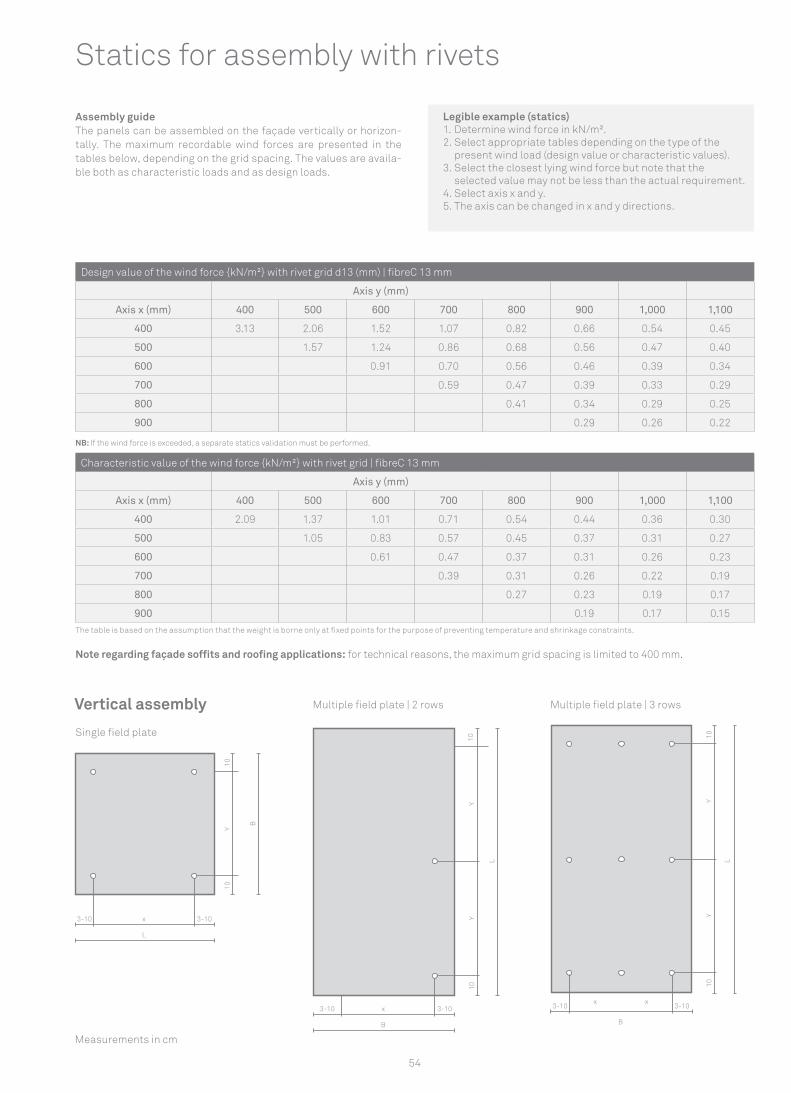
Design value of the wind force {kN/m²} with rivet grid d13 (mm) | fibreC 13 mm
Axis y (mm)
Axis x (mm) 400 500 600 700 800 900 1,000 1,100
400 3.13 2.06 1.52 1.07 0.82 0.66 0.54 0.45
500 1.57 1.24 0.86 0.68 0.56 0.47 0.40
600 0.91 0.70 0.56 0.46 0.39 0.34
700 0.59 0.47 0.39 0.33 0.29
800 0.41 0.34 0.29 0.25
900 0.29 0.26 0.22
Assembly guideThe panels can be assembled on the façade vertically or horizon-tally. The maximum recordable wind forces are presented in the tables below, depending on the grid spacing. The values are availa-ble both as characteristic loads and as design loads.
NB: If the wind force is exceeded, a separate statics validation must be performed.
Characteristic value of the wind force {kN/m²} with rivet grid | fibreC 13 mm
Axis y (mm)
Axis x (mm) 400 500 600 700 800 900 1,000 1,100
400 2.09 1.37 1.01 0.71 0.54 0.44 0.36 0.30
500 1.05 0.83 0.57 0.45 0.37 0.31 0.27
600 0.61 0.47 0.37 0.31 0.26 0.23
700 0.39 0.31 0.26 0.22 0.19
800 0.27 0.23 0.19 0.17
900 0.19 0.17 0.15
Measurements in cm
Vertical assembly
Statics for assembly with rivets
The table is based on the assumption that the weight is borne only at fixed points for the purpose of preventing temperature and shrinkage constraints.
Note regarding façade soffits and roofing applications: for technical reasons, the maximum grid spacing is limited to 400 mm.
Legible example (statics)1. Determine wind force in kN/m².2. Select appropriate tables depending on the type of the
present wind load (design value or characteristic values).3. Select the closest lying wind force but note that the
selected value may not be less than the actual requirement.4. Select axis x and y.5. The axis can be changed in x and y directions.
1010
B
L
x 3-10xx x3-10
yy
55
NoteAll the visualisations in the brochure are schematic representations of the system and structural-physical requirements and project details are not included in the data. The services provided by Rieder Smart Elements GmbH do not include static calculations. The sample calculation listed here does not dispense with an individual test by a structural designer. Rieder does not accept any liability for statics.
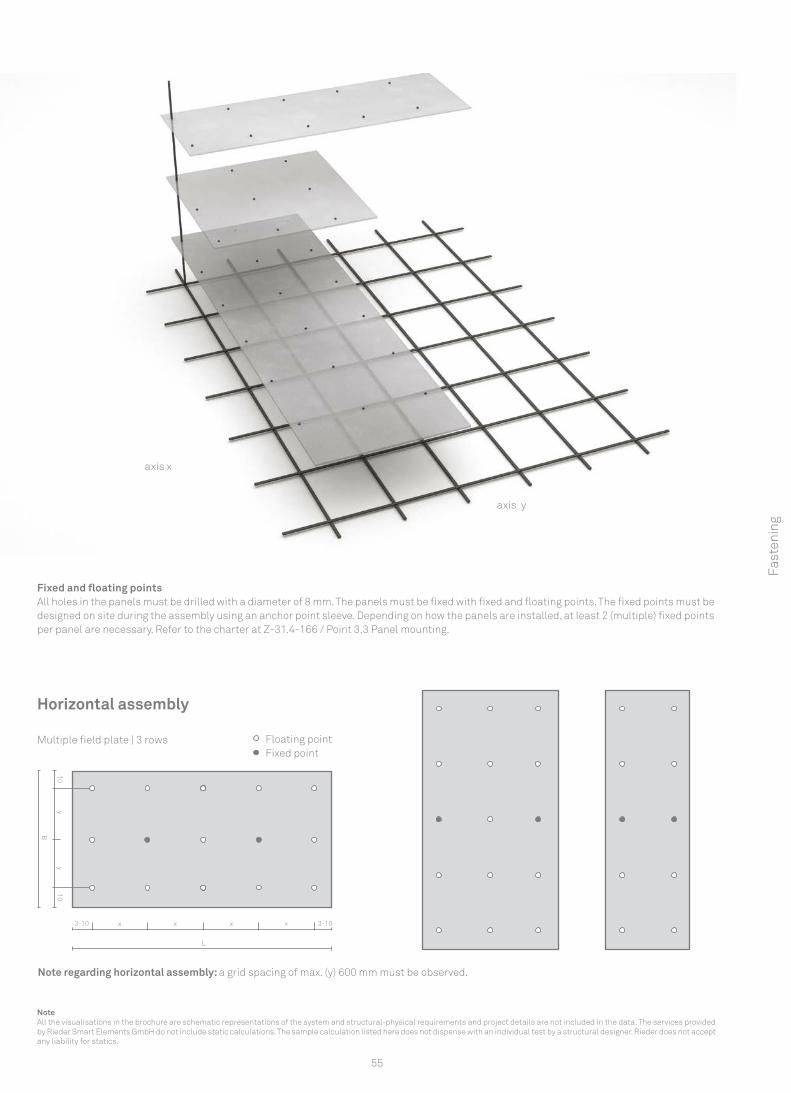
Fixed and floating points All holes in the panels must be drilled with a diameter of 8 mm. The panels must be fixed with fixed and floating points. The fixed points must be designed on site during the assembly using an anchor point sleeve. Depending on how the panels are installed, at least 2 (multiple) fixed points per panel are necessary. Refer to the charter at Z-31.4-166 / Point 3.3 Panel mounting.
Fast
enin
g
axis x
axis y
Horizontal assembly
Multiple field plate | 3 rows Floating pointFixed point
Note regarding horizontal assembly: a grid spacing of max. (y) 600 mm must be observed.
56
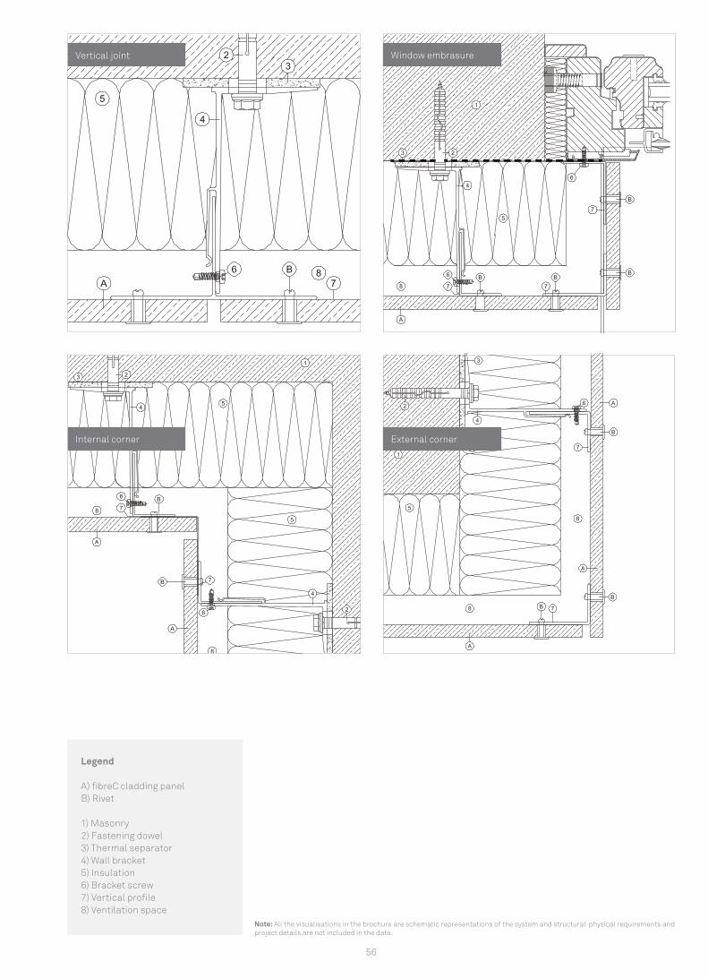
Internal corner External corner
Window embrasure
Legend
A) fibreC cladding panel B) Rivet
1) Masonry2) Fastening dowel3) Thermal separator4) Wall bracket5) Insulation6) Bracket screw7) Vertical profile8) Ventilation space
Vertical joint
Note: All the visualisations in the brochure are schematic representations of the system and structural-physical requirements and project details are not included in the data.
57
Fast
enin
g
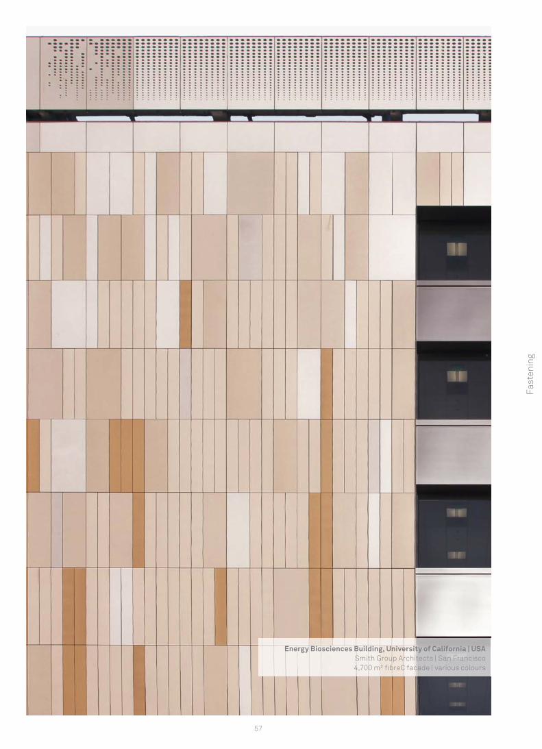
Energy Biosciences Building, University of California | USASmith Group Architects | San Francisco4,700 m² fi breC facade | various colours
1
4
6
3
2
5
6
7
58
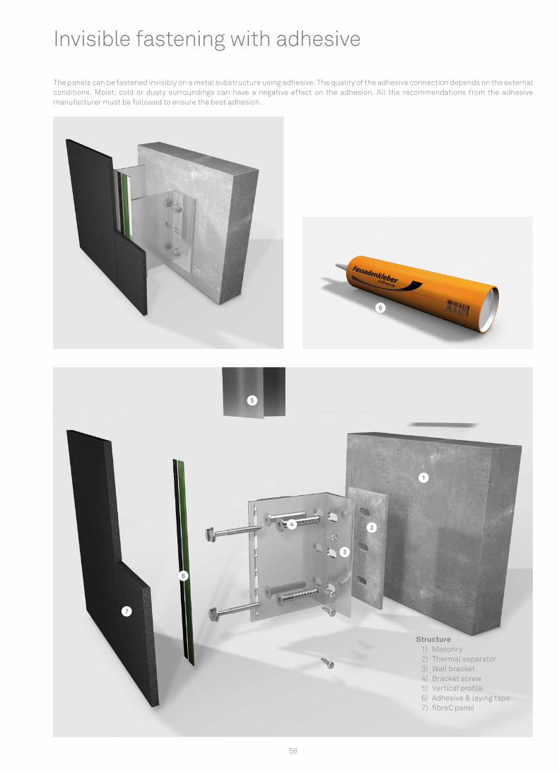
Structure 1) Masonry2) Thermal separator 3) Wall bracket 4) Bracket screw 5) Vertical profile 6) Adhesive & laying tape 7) fibreC panel
Invisible fastening with adhesive
The panels can be fastened invisibly on a metal substructure using adhesive. The quality of the adhesive connection depends on the external conditions. Moist, cold or dusty surroundings can have a negative effect on the adhesion. All the recommendations from the adhesive manufacturer must be followed to ensure the best adhesion.
xx
xx
x
L
B
B
L
x
L
x x
L
B
x
L
B
x
B
x
59
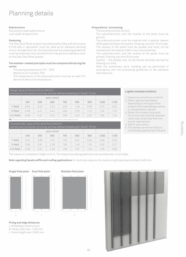
SubstructureExclusively metal substructure.Joint width at least 8 mm.
FasteningThe ‘Sika Tack Panel’ system manufactured by Sika with the licence Z-10.8-408 or equivalent must be used as an adhesive bonding mount. As a general rule, the manufacturer’s processing guidelines must be observed. Only certified firms may perform adhesive work on the Sika Tack Panel system.
The weather-related principles must be complied with during the works:
· Processing temperature: 5°C – 35°C · Maximum air humidity 75% · The temperature of the subconstruction must be at least 3°C
above the dew point temperature.
Preparations / processing · The bonding must be vertical. · The subconstruction and the reverse of the plate must be
ground. · The subconstruction must be cleaned with a special cleaner
(205) appertaining to the system. Drawing-out time 10 minutes · The reverse of the plate must be dusted and must not be
cleaned with the cleaner (205) in any circumstances. · The subconstruction and the reverse of the panel must be
primed. Drawing-out time 30 minutes · Caution – the panels may not be stored vertically during the
drawing-out time. · After the preliminary work, bonding can be performed in
accordance with the processing guidelines of the adhesive manufacturer.
Planning details
Fast
enin
g
Dual field plate
Fixing and edge distancesx Wheelbase substructureB Panel width max. 1,200 mmL Panel length max. 3,600 mm
Design value of the wind force {kN/m²}:vertical and horizontal mounting. vertical adhesive beads grid | fibreC 13 mm
axis x (mm)
400 500 600 700 800 900 1,000 1,100
1-field 8.64 5.53 3.22 2.03 1.36 0.95 0.70 0.52
2-field 5.39 4.21 3.42 2.85 2.18 1.72 1.40 1.15
≥ 3-field 5.39 4.21 3.42 2.85 2.42 2.01 1.63 1.34
NB: If the wind force is exceeded, a separate statics validation must be performed.
Characteristic value of the wind force {kN/m²}:vertical and horizontal mounting. vertical adhesive beads grid | fibreC 13 mm
axis x (mm)
400 500 600 700 800 900 1,000 1,100
1-field 5.76 3.69 2.15 1.35 0.91 0.64 0.46 0.35
2-field 3.59 2.81 2.28 1.90 1.45 1.15 0.93 0.77
≥ 3-field 3.59 2.81 2.28 1.90 1.61 1.34 1.09 0.89
Legible examples (statics)
1. Determine wind force in kN/m².2. Select appropriate tables
depending on the type of the present wind load (design values or characteristic values).
3. Select the closest lying wind force; but note that the selected value may not be less than the actual requirement.
4. Select axis x and y.5. The panels can be vertically or
horizontally applied with the grid.
Single field plate Multiple field plate
The maximum installation height is 22 m. The respective state guidelines must be observed, on principle.
Note regarding façade soffits and roofing applications: for technical reasons, the maximum grid spacing is limited to 400 mm.
60
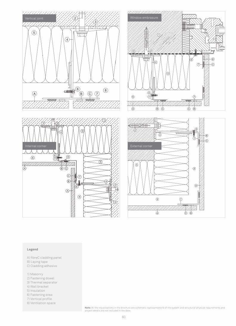
Legend
A) fibreC cladding panel B) Laying tape C) Cladding adhesive
1) Masonry2) Fastening dowel3) Thermal separator4) Wall bracket5) Insulation6) Fastening srew7) Vertical profile8) Ventilation space
Internal corner External corner
Window embrasure
Note: All the visualisations in the brochure are schematic representations of the system and structural-physical requirements and project details are not included in the data.
Vertical joint

61
Fast
enin
g
Copernikus Science Center Warsaw | PolandArchitekt Jan Kubec, Warsaw
13,000 m² fi breC 13 facade | various colours
62
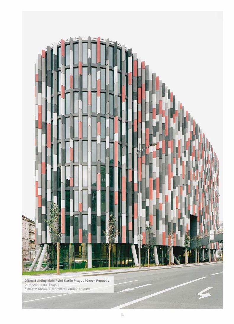
Offi ce Building Main Point Karlin Prague | Czech RepublicDaM Architects | Prague6,800 m² fi breC 3D elements | various colours
63
ProcessingPreparation.............................................................................................................................................................................................................64Cutting............................................................................................................................................................................................64Drilling.............................................................................................................................................................................................................65Fastening with undercut anchor..........................................................................................................................................................................65Fastening with rivets..............................................................................................................................................................................................66Adhesion..........................................................................................................................................................................................................66
Pro
cess
ing
64
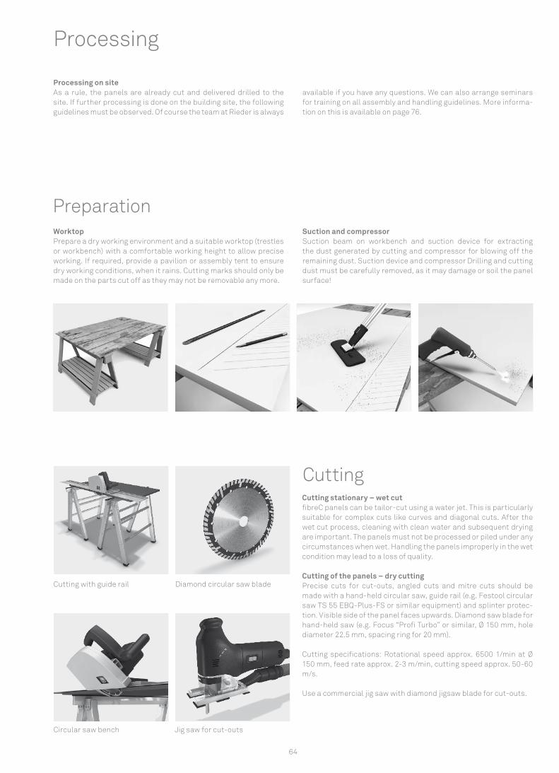
Processing
Processing on site As a rule, the panels are already cut and delivered drilled to the site. If further processing is done on the building site, the following guidelines must be observed. Of course the team at Rieder is always
available if you have any questions. We can also arrange seminars for training on all assembly and handling guidelines. More informa-tion on this is available on page 76.
WorktopPrepare a dry working environment and a suitable worktop (trestles or workbench) with a comfortable working height to allow precise working. If required, provide a pavilion or assembly tent to ensure dry working conditions, when it rains. Cutting marks should only be made on the parts cut off as they may not be removable any more.
Suction and compressorSuction beam on workbench and suction device for extracting the dust generated by cutting and compressor for blowing off the remaining dust. Suction device and compressor Drilling and cutting dust must be carefully removed, as it may damage or soil the panel surface!
Cutting stationary – wet cutfibreC panels can be tailor-cut using a water jet. This is particularly suitable for complex cuts like curves and diagonal cuts. After the wet cut process, cleaning with clean water and subsequent drying are important. The panels must not be processed or piled under any circumstances when wet. Handling the panels improperly in the wet condition may lead to a loss of quality.
Cutting of the panels – dry cuttingPrecise cuts for cut-outs, angled cuts and mitre cuts should be made with a hand-held circular saw, guide rail (e.g. Festool circular saw TS 55 EBQ-Plus-FS or similar equipment) and splinter protec-tion. Visible side of the panel faces upwards. Diamond saw blade for hand-held saw (e.g. Focus “Profi Turbo” or similar, Ø 150 mm, hole diameter 22.5 mm, spacing ring for 20 mm).
Cutting specifications: Rotational speed approx. 6500 1/min at Ø 150 mm, feed rate approx. 2-3 m/min, cutting speed approx. 50-60 m/s.
Use a commercial jig saw with diamond jigsaw blade for cut-outs.
Cutting
Cutting with guide rail Diamond circular saw blade
Jig saw for cut-outsCircular saw bench
Preparation

65
Blue Granit drill Ø 8 mm Drilling jig
Undercut anchor bore Undercut anchor bore
DrillingThroughholesUse a masonry drill (e.g. Bosch „Blue Granite“ Ø 8 mm, l = 120 mm or similar) or special drill (e.g. Hufschmid) with Ø 8 mm, never use an impact drill! Visible side of the panels faces upwards. Use solid wood or wood-based worktop as support to avoid tearing or splinte-ring on the underside of the panels.
Apply adhesive tape on the drilling site before marking and make the markings on the adhesive tape, as markings may not be removable.
Undercut anchor drillingUsually drillings are performed at the production site. In the case of additional drilling work at the building site: In accordance with approval, system components and instruments (undercut drilling unit, drill bit, anchor and gauges) supplied by Keil must be used. Undercut anchor seating depth 8.5 mm, training by Firma Keil is recommended, please comply with drilling guidelines of the manu-facturer.
Visible side of the panel faces downwards, put an intermediate layer, e.g. a carpet, onto the workbench as protection. Compressor for sucking the undercut drilling unit to the panel and removing the residual cutting and drilling dust.
Required equipmentUndercut anchor drilling unit for additional drilling work required at the building site, undercut anchor Hs = 8,5 mm, undercut screw (length depending on agraffe), gauge for checking the drill, com-pressor, torque wrench. All components and devices must be part of the same system and compatible with each other (supplier Keil, www.keil.eu); the manufacturer’s installation guidelines must be complied with!
Undercut screws must be fastened with a torque of 2.50 – 4.00 Nm. Attention- if the screws are too long, the drilling hole penetrates the front side of the panel. Foam rubber layer between panel and agraffe depending on substructure; adjust panels with setting screws. Fasten one agraffe per panel to the support rail as fi xed point.
Undercut anchor Pro
cess
ing
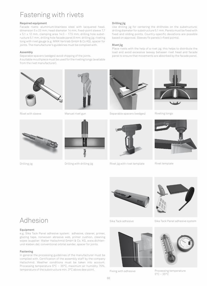
66
Fastening with rivetsRequired equipmentFacade rivets: aluminium/stainless steel with lacquered head, dimension 5 x 23 mm; head diameter 14 mm, fi xed-point sleeve 7.7 x 5.1 x 12 mm, clamping area 14.0 – 17.5 mm; drilling hole subst-ructure 5.1 mm, drilling hole facade panel 8 mm; drilling jig; riveting tong with rivet gauge (e.g. MWK Vertrieb GmbH & Co KG), spacer for joints. The manufacturer’s guidelines must be complied with.
AssemblySeparable spacers (wedges) avoid chipping of the joints.A suitable mouthpiece must be used for the riveting tongs (available from the rivet manufacturer).
Drilling jigUse drilling jig for centering the drillholes on the substructure; drilling diameter for substructure 5.1 mm. Panels must be fi xed with fi xed and sliding points. Country-specifi c deviations are possible based on approval. Sleeves fi x panels (=fi xed points).
Rivet jigPlace rivets with the help of a rivet jig; this helps to distribute the load and avoid excessive leeway between rivet head and facade panel to ensure that movements are absorbed by the facade panel.
Rivet with sleeve Manuel rivet gun Separable spacers (wedges) Riveting tongs
Drilling jig Drilling with drilling jig Rivet jig with rivet template Rivet template
Equipmente.g. Sika Tack Panel adhesive system: adhesive, cleaner, primer, glazing tape, nonwoven abrasive web, primer cushion, cleaning wipes (supplier: Walter Hallschmid GmbH & Co. KG, www.dichten-und-kleben.de); conventional orbital sander, spacer for joints.
FasteningIn general the processing guidelines of the manufacturer must be complied with. Certifi cation of the assembly staff by the company Hallschmid. Weather conditions must be taken into account. Processing temperature 5°C – 35°C, maximum air humidity 75%, temperature of the substructure min. 3°C above dew point.
Adhesion Sika Tack adhesive Sika Tack Panel adhesive system
Fixing with adhesive Processing temperature5°C – 35°C

67
Quotation and orderFrom enquiry to delivery........................................................................................................................................................................................68
Quo
tati
on a
nd O
rder

68
Quality management for order processes The Rieder group not only places great value on sustainability and the quality of their products, but also the satisfaction of their cus-tomers. Processors are just as important a link here in the network as architects, engineers and developers. To provide the right prod-uct for each individual project, all general conditions should be clarified beforehand.
Clarity of orderAccurate documentation on agreements facilitates the smooth running of projects. Clarity of order exists as soon as all project-related measurements, informations and payments are provided.
The characteristics of fibreC described in the brochure help to avoid misunderstandings or false customer expectations. The fibreC Handling Instructions provide guidance on how to handle the high-quality glassfibre reinforced concrete panels during transport, storage and cleaning.
Planning a fibreC cladding for a building? Contact us for a non-committal appointment and a quotation. You can find a checklist for getting a quote in the download centre on our website. We can also send you the form by fax or e-mail.
Contact: [email protected] or +49 / (0)8031 / 90167-163
Step 1 I Checklist quotation We need the following information to give you a quote:
· Project name, project address · Name of the architect or the architect’s office · Product type fibreC panel (Exterior, Interior, Special, öko skin) · Application (e.g. cladding, internal wall, floor etc.) · Type of build (new build, renovation) · Type of project (public building, office block, school, private
house etc.) · Total m² fibreC panels · m² per cladding side (optional) · Colour(s) · Surface(s) · Planned type of fastening (rivets, adhesive, undercut) · Planned awarding of contract · Invoice address · Delivery address · Desired delivery date
Step 2 I Price suggestion / Quotation After you have provided all the data above, you will receive a quota-tion and an expected delivery date from us.
Step 3 I Placing of order After the order is placed, you will receive an exact delivery date. You will also receive the information as to by when we need the detailed data for the production of your panels.
Step 4 I Primary production To meet the delivery time given, the raw panels are produced before all cuts and special processing are announced and they harden for 28 days.
Step 5 I Announcement of sizes and cutting measures 6 weeks before dispatch we need the project-related measure-ments.
All measurements and details must be with us by the above men-tioned deadline.
· Cutting measures (dimensions between centre lines) in the form of an Excel table (Rieder order template)
· Special processing (bores, bore dimensions, diagonal cuts, mitre cuts etc.)
Note: If, despite the binding confirmation of the deadline for the submission for the cutting measurements and other data, you can-not meet the deadline, you will of course understand that the pro-duction schedule and thus the delivery time will be extended. This may lead to longer-term delays, because the entire production pro-cess is pre-planned over several weeks. Failure to comply with the deadline may lead to processing costs for the resulting reschedul-ing of productions being charged.
Step 6 I Updated order confirmation After notification of all cutting measurements and special process-ing, you will receive an updated order confirmation with final meas-urements.
Step 7 I Final production and packaging
Step 8 I Delivery (Incoterms 2010 FCA)We organise the delivery on the day of the provision of your panels. You get the information when the panels are going to be delivered. By request you can also organise the transport yourself. We pro-vide you with all the data needed. If the goods can not be collected within two weeks, storage costs may be charged.
Quotation and order
* Process applies for fibreC standard panels. When ordering fibreC formparts and fibreC fins, there may be variances in the procedure or the time line.
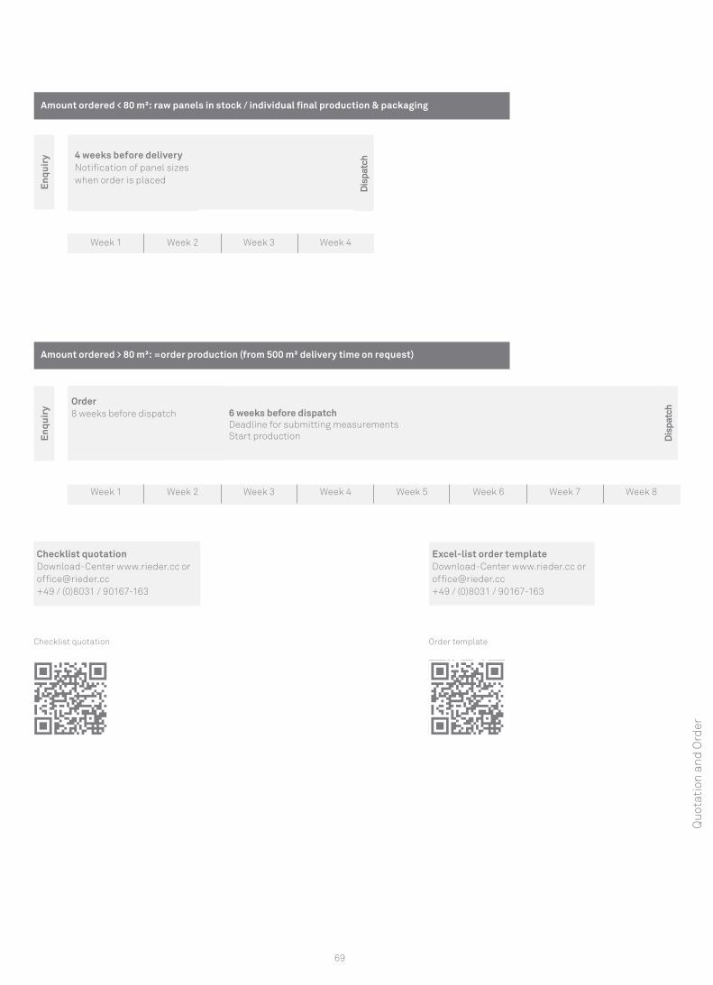
69
Enqu
iry 4 weeks before delivery
Notification of panel sizes when order is placed
Week 1 Week 2 Week 3 Week 4
Dis
patc
h
Amount ordered < 80 m²: raw panels in stock / individual final production & packaging
Checklist quotation Download-Center www.rieder.cc or [email protected]+49 / (0)8031 / 90167-163
Excel-list order template Download-Center www.rieder.cc or [email protected]+49 / (0)8031 / 90167-163
Amount ordered > 80 m²: =order production (from 500 m² delivery time on request)
Week 1 Week 2 Week 3 Week 4 Week 5 Week 6 Week 7 Week 8
6 weeks before dispatch Deadline for submitting measurements Start production En
quir
y
Order8 weeks before dispatch
Checklist quotation Order template
Dis
patc
h
Quo
tati
on a
nd O
rder
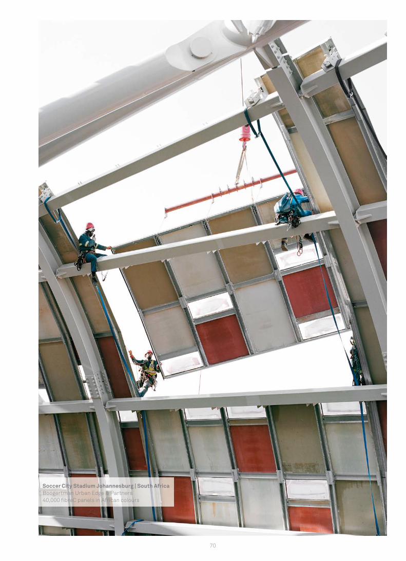
70
Soccer City Stadium Johannesburg | South AfricaBoogertman Urban Edge & Partners40,000 fi breC panels in African colours

71
Handling and ServiceLoading and securing for transport......................................................................................................................................................................72Storage......................................................................................................................................................................................................72Handling.......................................................................................................................................................................................................73Cleaning.....................................................................................................................................................................................................................74Repair kit................................................................................................................................................................................................................. 75Customer service.....................................................................................................................................................................................................76Contact details....................................................................................................................................................................................................... 80
Han
dlin
g &
Ser
vice
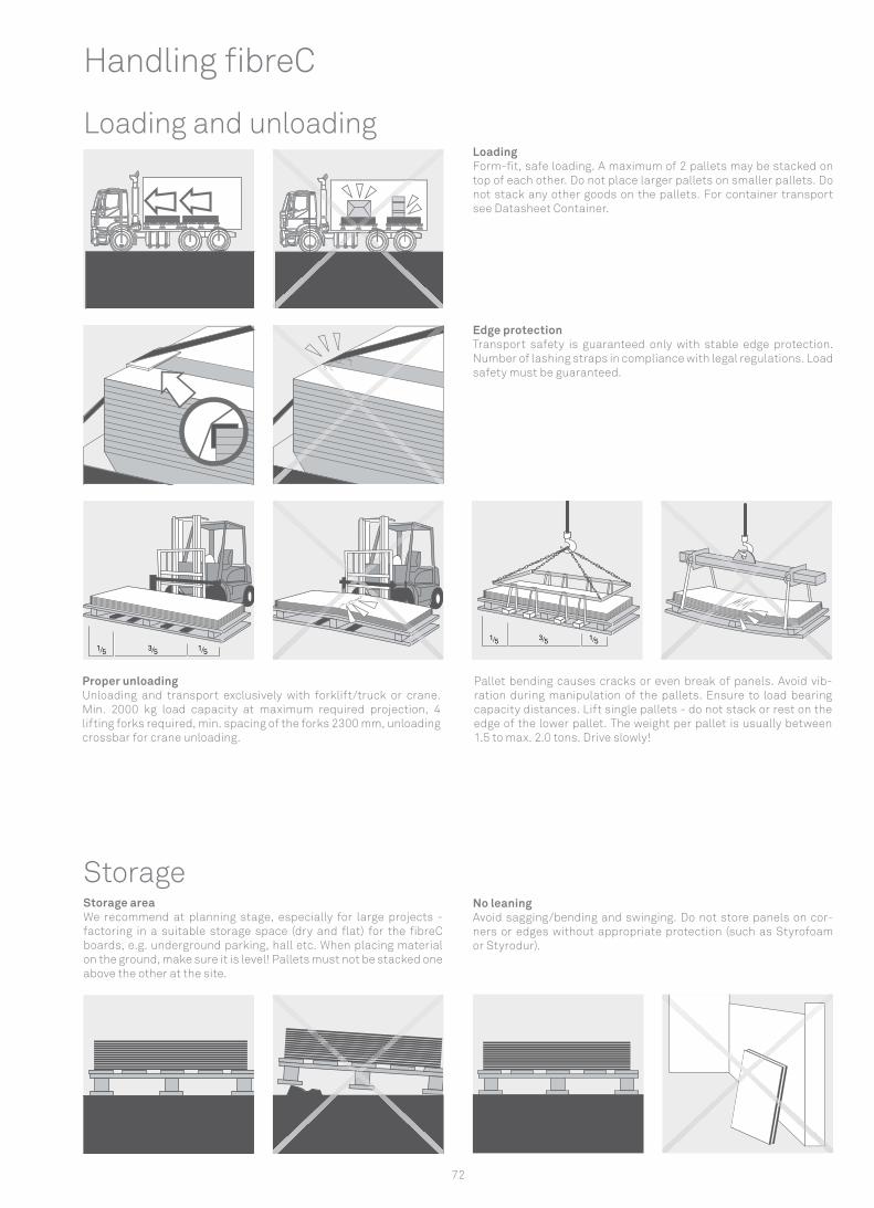
1/5 3/5 1/5
1/5 3/5 1/5
72
Handling fi breC
Loading and unloadingLoading Form-fi t, safe loading. A maximum of 2 pallets may be stacked on top of each other. Do not place larger pallets on smaller pallets. Do not stack any other goods on the pallets. For container transport see Datasheet Container.
Edge protection Transport safety is guaranteed only with stable edge protection. Number of lashing straps in compliance with legal regulations. Load safety must be guaranteed.
Storage No leaning Avoid sagging/bending and swinging. Do not store panels on cor-ners or edges without appropriate protection (such as Styrofoam or Styrodur).
Storage area We recommend at planning stage, especially for large projects - factoring in a suitable storage space (dry and fl at) for the fi breC boards, e.g. underground parking, hall etc. When placing material on the ground, make sure it is level! Pallets must not be stacked one above the other at the site.
Proper unloading Unloading and transport exclusively with forklift/truck or crane. Min. 2000 kg load capacity at maximum required projection, 4 lifting forks required, min. spacing of the forks 2300 mm, unloading crossbar for crane unloading.
Pallet bending causes cracks or even break of panels. Avoid vib-ration during manipulation of the pallets. Ensure to load bearing capacity distances. Lift single pallets - do not stack or rest on the edge of the lower pallet. The weight per pallet is usually between 1.5 to max. 2.0 tons. Drive slowly!
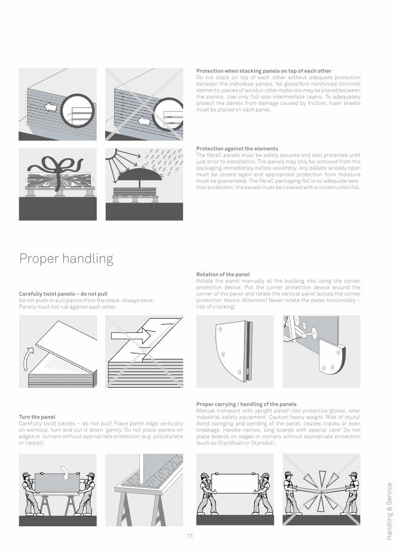
73
Protection against the elements The fi breC panels must be safely secured and well protected until just prior to installation. The panels may only be removed from the packaging immediately before assembly. Any pallets already open must be closed again and appropriate protection from moisture must be guaranteed. The fi breC packaging foil is no adequate wea-ther protection, the panels must be covered with a construction foil.
Protection when stacking panels on top of each other Do not stack on top of each other without adequate protection between the individual panels. No glassfi bre-reinforced concrete elements, pieces of wood or other materials may be placed between the panels. Use only full-size intermediate layers. To adequately protect the panels from damage caused by friction, foam sheets must be placed on each panel.
Proper handling
Carefully twist panels – do not pull Do not push or pull panels from the stack. Always twist. Panels must not rub against each other.
Rotation of the panelRotate the panel manually at the building site using the corner protection device. Put the corner protection device around the corner of the panel and rotate the vertical panel across the corner protection device. Attention! Never rotate the panel horizontally – risk of cracking!
Turn the panel Carefully twist panels – do not pull! Place panel edge vertically on worktop, turn and put it down gently. Do not place panels on edges or corners without appropriate protection (e.g. polystyrene or carpet).
Proper carrying / handling of the panels Manual transport with upright panel! Use protective gloves, wear industrial safety equipment. Caution heavy weight. Risk of injury! Avoid swinging and bending of the panel, causes cracks or even breakage. Handle narrow, long boards with special care! Do not place boards on edges or corners without appropriate protection (such as Styrofoam or Styrodur).
Han
dlin
g &
Ser
vice
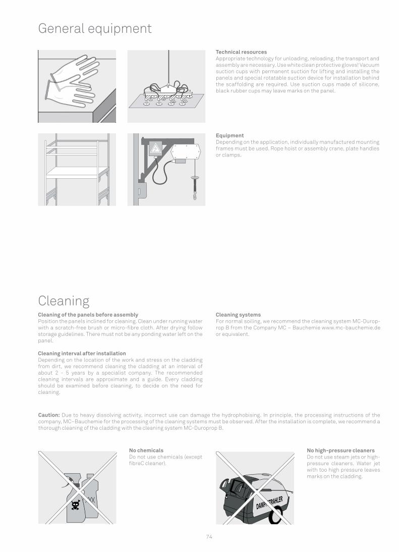
74
CleaningCleaning of the panels before assembly Position the panels inclined for cleaning. Clean under running water with a scratch-free brush or micro-fibre cloth. After drying follow storage guidelines. There must not be any ponding water left on the panel.
Cleaning interval after installation Depending on the location of the work and stress on the cladding from dirt, we recommend cleaning the cladding at an interval of about 2 - 5 years by a specialist company. The recommended cleaning intervals are approximate and a guide. Every cladding should be examined before cleaning, to decide on the need for cleaning.
Cleaning systems For normal soiling, we recommend the cleaning system MC-Durop-rop B from the Company MC – Bauchemie www.mc-bauchemie.de or equivalent.
No chemicals Do not use chemicals (except fibreC cleaner).
No high-pressure cleaners Do not use steam jets or high-pressure cleaners. Water jet with too high pressure leaves marks on the cladding.
General equipment
Technical resources Appropriate technology for unloading, reloading, the transport and assembly are necessary. Use white clean protective gloves! Vacuum suction cups with permanent suction for lifting and installing the panels and special rotatable suction device for installation behind the scaffolding are required. Use suction cups made of silicone, black rubber cups may leave marks on the panel.
EquipmentDepending on the application, individually manufactured mounting frames must be used. Rope hoist or assembly crane, plate handles or clamps.
Caution: Due to heavy dissolving activity, incorrect use can damage the hydrophobising. In principle, the processing instructions of the company, MC–Bauchemie for the processing of the cleaning systems must be observed. After the installation is complete, we recommend a thorough cleaning of the cladding with the cleaning system MC-Duroprop B.
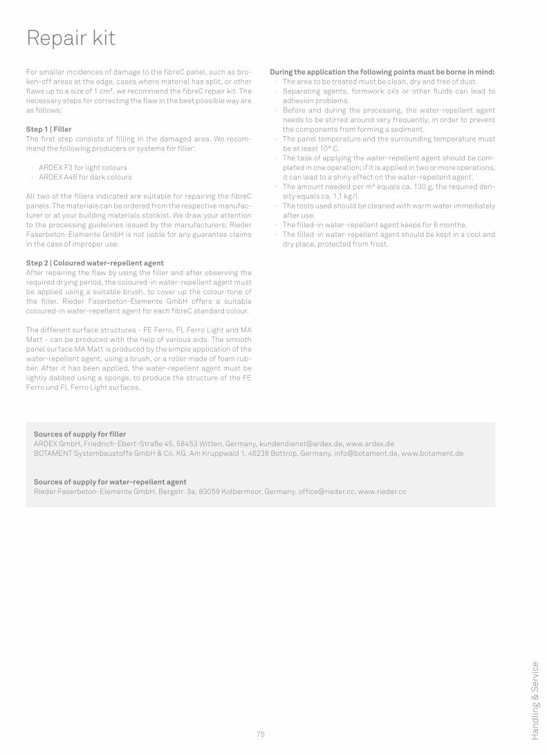
75
Repair kitFor smaller incidences of damage to the fibreC panel, such as bro-ken-off areas at the edge, cases where material has split, or other flaws up to a size of 1 cm², we recommend the fibreC repair kit. The necessary steps for correcting the flaw in the best possible way are as follows:
Step 1 | FillerThe first step consists of filling in the damaged area. We recom-mend the following producers or systems for filler:
· ARDEX F3 for light colours · ARDEX A46 for dark colours
All two of the fillers indicated are suitable for repairing the fibreC panels. The materials can be ordered from the respective manufac-turer or at your building materials stockist. We draw your attention to the processing guidelines issued by the manufacturers; Rieder Faserbeton-Elemente GmbH is not liable for any guarantee claims in the case of improper use.
Step 2 | Coloured water-repellent agentAfter repairing the flaw by using the filler and after observing the required drying period, the coloured-in water-repellent agent must be applied using a suitable brush, to cover up the colour tone of the filler. Rieder Faserbeton-Elemente GmbH offers a suitable coloured-in water-repellent agent for each fibreC standard colour.
The different surface structures - FE Ferro, FL Ferro Light and MA Matt - can be produced with the help of various aids. The smooth panel surface MA Matt is produced by the simple application of the water-repellent agent, using a brush, or a roller made of foam rub-ber. After it has been applied, the water-repellent agent must be lightly dabbed using a sponge, to produce the structure of the FE Ferro und FL Ferro Light surfaces.
During the application the following points must be borne in mind: · The area to be treated must be clean, dry and free of dust. · Separating agents, formwork oils or other fluids can lead to
adhesion problems. · Before and during the processing, the water-repellent agent
needs to be stirred around very frequently, in order to prevent the components from forming a sediment.
· The panel temperature and the surrounding temperature must be at least 10° C.
· The task of applying the water-repellent agent should be com-pleted in one operation; if it is applied in two or more operations, it can lead to a shiny effect on the water-repellent agent.
· The amount needed per m² equals ca. 130 g, the required den-sity equals ca. 1.1 kg/l.
· The tools used should be cleaned with warm water immediately after use.
· The filled-in water-repellent agent keeps for 6 months. · The filled-in water-repellent agent should be kept in a cool and
dry place, protected from frost.
Sources of supply for fillerARDEX GmbH, Friedrich-Ebert-Straße 45, 58453 Witten, Germany, [email protected], www.ardex.deBOTAMENT Systembaustoffe GmbH & Co. KG, Am Kruppwald 1, 46238 Bottrop, Germany, [email protected], www.botament.de
Sources of supply for water-repellent agentRieder Faserbeton-Elemente GmbH, Bergstr. 3a, 83059 Kolbermoor, Germany, [email protected], www.rieder.cc
Han
dlin
g &
Ser
vice
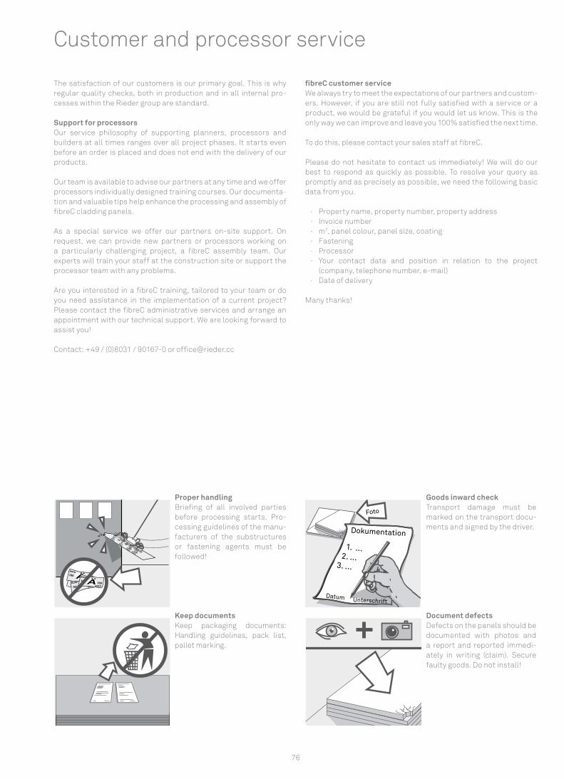
Äeuro
euro
ÄeuroeuroÄ
euro
euro
Äeuro
euro100 100
100
100
Dokumentation
1. ... 2. ...3. ...
UnterschriftDatum
Foto
76
The satisfaction of our customers is our primary goal. This is why regular quality checks, both in production and in all internal pro-cesses within the Rieder group are standard.
Support for processors Our service philosophy of supporting planners, processors and builders at all times ranges over all project phases. It starts even before an order is placed and does not end with the delivery of our products.
Our team is available to advise our partners at any time and we offer processors individually designed training courses. Our documenta-tion and valuable tips help enhance the processing and assembly of fibreC cladding panels.
As a special service we offer our partners on-site support. On request, we can provide new partners or processors working on a particularly challenging project, a fibreC assembly team. Our experts will train your staff at the construction site or support the processor team with any problems. Are you interested in a fibreC training, tailored to your team or do you need assistance in the implementation of a current project? Please contact the fibreC administrative services and arrange an appointment with our technical support. We are looking forward to assist you!
Contact: +49 / (0)8031 / 90167-0 or [email protected]
fibreC customer service We always try to meet the expectations of our partners and custom-ers. However, if you are still not fully satisfied with a service or a product, we would be grateful if you would let us know. This is the only way we can improve and leave you 100% satisfied the next time.
To do this, please contact your sales staff at fibreC.
Please do not hesitate to contact us immediately! We will do our best to respond as quickly as possible. To resolve your query as promptly and as precisely as possible, we need the following basic data from you.
· Property name, property number, property address · Invoice number · m2, panel colour, panel size, coating · Fastening · Processor · Your contact data and position in relation to the project
(company, telephone number, e-mail) · Date of delivery
Many thanks!
Customer and processor service
Goods inward checkTransport damage must be marked on the transport docu-ments and signed by the driver.
Keep documents Keep packaging documents: Handling guidelines, pack list, pallet marking.
Document defects Defects on the panels should be documented with photos and a report and reported immedi-ately in writing (claim). Secure faulty goods. Do not install!
Proper handling Briefing of all involved parties before processing starts. Pro-cessing guidelines of the manu-facturers of the substructures or fastening agents must be followed!
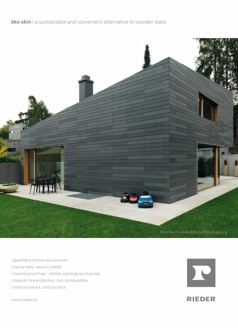
| glassfibre reinforced concrete
| handy slats, easy to install
| maintenance free - neither painting nor staining
| class A1 fire protection, non-combustible
| various colours, vivid surface
www.rieder.cc
öko skin | a sustainable and convenient alternative to wooden slats
Titus Bernhard Architects BDA, Augsburg
78

79
In the natural flow of materials, glaciers wash sediment into the valley and thus set the mineral material in motion.
These natural raw materials from nature are used by Rieder to make concrete products. This gives the material something familiar, living and a uniquely honest material character.
The mission of preserving this authenticity is reflected in Rieder’s concrete products.Rieder. Bringing concrete to life.
Beton lebt.
80
Contact Rieder Group
NoteThis brochure contains basic descriptions and information on fibreC glassfibre reinforced concrete panels.
The descriptions of the product characteristics should not be con-sidered a guarantee. All information, including technical informa-tion and drawings, is up to date and based on our own experience. The service provided by Rieder Smart Elements GmbH extends to fibreC panels but explicitly not to fastening materials or substruc-tures. The applications described here are examples only and do not take account of the specific conditions associated with indi-vidual cases. The information and suitability of the material for the intended use must be checked with respect to each individual project. Despite careful checking, we cannot accept liability for accuracy, completeness or actuality. This applies, in particular, to print errors and subsequent changes to technical information. Reference to this will be made in the contract to the agreement to be concluded, which takes precedence over information provided here.
Please get in touch with your local fibreC sales partner or contact Rieder directly for more information on sales terms, availability, prices, etc. The latest version of these technical documents is avail-able for download under www.rieder.cc.
Safeguarding external copyrightRieder is committed to respecting all the copyrights of the graphics, photos and texts, to using our own graphics, photos and reverting to texts or to use graphics, photos and texts in the public domain. If there is an unmarked graphic, photo or text protected by external copyright, the copyright could not be determined by Rieder. In the case of such an unintentional copyright violation, Rieder will remove the item upon notification or indicate the appropriate copyright.
All information, logos, text, graphics and images are subject to copyright. They are, if no other reservations, property of Rieder Smart Elements GmbH. The processing and use in media is allowed only with prior written permission of Rieder.
Photos Rasmus Norlander, Ditz Fejer, Jens Kirchner, Herta Hurnaus, Daniel Lunghi, David Matthiessen, Sabrina Scheja, Frank Aussieker
Visualisations vertex nine, kirchner&kirchner
Paper Printed on FSC-certified paper.
Sales Rieder Smart Elements GmbHMühlenweg 225751 MaishofenAustria
T: +43 / (0)6542 / 690 844F: +43 / (0)6542 / 690 855E-mail: [email protected]
ProductionRieder Faserbeton-Elemente GmbHBergstr. 3a83059 KolbermoorGermany
T: +49 / (0)8031 / 90167-0F: +49 / (0)8031 / 90167-169E-mail: [email protected]
You can find the contact details of your local sales person and our international partner network under www.rieder.cc.
Your feedback is important to us! We continually strive to improve our products and all processes associated with development, manufacturing and processing.
This aim of the brochure is to provide a user-friendly guide to fibreC glassfibre cladding, its areas of application and application options. So please let us know how it works and share your experience with us! This will help us improve our product, range and installation ins-tructions.
Thank you!
T: +43 / (0)6542 / 690 150E-mail: [email protected]