Fibre reinforced bioresorbable composites for spinal surgery
13
Fibre reinforced bioresorbable composites for spinal surgery Mikko Huttunen * , Nureddin Ashammakhi, Pertti To ¨rma ¨la ¨, Minna Kelloma ¨ki Tampere University of Technology, Institute of Biomaterials, Hermiankatu 12 A, P.O. Box 589, FIN-33101 Tampere, Finland Received 15 June 2005; received in revised form 23 March 2006; accepted 30 March 2006 Abstract Composites containing different amounts of b-tricalcium phosphate (b-TCP) embedded in a poly-lactide (PLA70) matrix with and without poly-lactide (PLA96) fibre reinforcement were studied and the feasibility of using these composites in spinal fusion implants was examined. Compressive yield strength was measured in two directions: parallel to (83–97 MPa) and perpendicular to (108– 123 MPa) the laminated structure of the composites. In the parallel direction, the addition of b-TCP decreased compressive yield strength while in the perpendicular direction this was increased when compared to plain specimens (p < 0.05). Fibre reinforcement had no signif- icant effect on compressive yield strength (p < 0.05), but did increase impact strength by 127–216% for notched specimens (parallel direc- tion) and by about 65% for un-notched specimens (perpendicular direction) (p < 0.05). A 24 week in vitro analysis of implant prototypes in simulated body fluid revealed a decrease in compressive yield strength, which was greater for the samples containing 50 wt.% b-TCP than for those containing 25 wt.% b-TCP. After 12 weeks incubation the composites retained 66–99% of their initial compressive strength, depending on composition. After 24 weeks incubation the lowest compressive strength was 51% (56 MPa: 50/50) and the high- est was 94% (90 MPa: 75/25) of the initial value. Calcium phosphate precipitation on the surfaces of the materials in vitro was also observed. The initial compressive strengths of the studied composites were comparable to materials used in spinal fusion applications, but adequate strength retention behaviour needs to be confirmed before undertaking clinical experiments. Ó 2006 Acta Materialia Inc. Published by Elsevier Ltd. All rights reserved. Keywords: Biomaterials; Composites; Fibres; Polymers; Ceramics 1. Introduction Low back pain is one of the most common medical con- ditions in the Western world and is the fifth most common cause of lost time at work [1,2]. It has also been reported that spinal surgery is the fastest growing field in musculo- skeletal surgery with a global market value estimated at 1.2 billion $ [3]. According to estimates, two-thirds of the US population suffer back pain and over 6 million patients have severe back pain that requires medical consultation [4]. Pain is usually alleviated by analgetics, anti-inflamma- tory drugs, muscle relaxants, or by different combinations of such drugs, and only 1–2% of all patients with back pain require surgical intervention, such as discectomy and/or spinal fusion [4,5]. Spinal fusion means surgical immobilization of the spine by joining two or more vertebrae, creating a bony union. In fusion operations the motion segment between the verte- brae is traditionally replaced by the use of ‘‘gold standard’’ autogenous bone graft material. The disk space may also be replaced by medical implants called interbody fusion devices (IBFDs) such as fusion cages, which hold the bone graft material within them. Various materials for IBFDs have been studied including metals [6–8], polymers [9–27], ceramics [28–30], composites [7,10,31,32] and allogenic bone products, ‘‘biological cages’’ [33]. Metallic IBFDs have proven to be effective in fusion operations [6,8], but the high strength of metals may lead to further problems, such as stress shielding, reduction of blood supply at the implantation site and the possibility of corrosion wear and debris formation [34]. The high strength of metals may also increase the risk of implant subsidence into verte- brae [35]. Another possible drawback of certain metals is 1742-7061/$ - see front matter Ó 2006 Acta Materialia Inc. Published by Elsevier Ltd. All rights reserved. doi:10.1016/j.actbio.2006.03.008 * Corresponding author. Tel.: +358 3 3115 2481; fax: +358 3 3115 2250. E-mail address: mikko.huttunen@tut.fi (M. Huttunen). Acta Biomaterialia 2 (2006) 575–587 www.actamat-journals.com
-
Upload
mikko-huttunen -
Category
Documents
-
view
213 -
download
1
Transcript of Fibre reinforced bioresorbable composites for spinal surgery

Acta Biomaterialia 2 (2006) 575–587
www.actamat-journals.com
Fibre reinforced bioresorbable composites for spinal surgery
Mikko Huttunen *, Nureddin Ashammakhi, Pertti Tormala, Minna Kellomaki
Tampere University of Technology, Institute of Biomaterials, Hermiankatu 12 A, P.O. Box 589, FIN-33101 Tampere, Finland
Received 15 June 2005; received in revised form 23 March 2006; accepted 30 March 2006
Abstract
Composites containing different amounts of b-tricalcium phosphate (b-TCP) embedded in a poly-lactide (PLA70) matrix with andwithout poly-lactide (PLA96) fibre reinforcement were studied and the feasibility of using these composites in spinal fusion implantswas examined. Compressive yield strength was measured in two directions: parallel to (83–97 MPa) and perpendicular to (108–123 MPa) the laminated structure of the composites. In the parallel direction, the addition of b-TCP decreased compressive yield strengthwhile in the perpendicular direction this was increased when compared to plain specimens (p < 0.05). Fibre reinforcement had no signif-icant effect on compressive yield strength (p < 0.05), but did increase impact strength by 127–216% for notched specimens (parallel direc-tion) and by about 65% for un-notched specimens (perpendicular direction) (p < 0.05). A 24 week in vitro analysis of implant prototypesin simulated body fluid revealed a decrease in compressive yield strength, which was greater for the samples containing 50 wt.% b-TCPthan for those containing 25 wt.% b-TCP. After 12 weeks incubation the composites retained 66–99% of their initial compressivestrength, depending on composition. After 24 weeks incubation the lowest compressive strength was 51% (56 MPa: 50/50) and the high-est was 94% (90 MPa: 75/25) of the initial value. Calcium phosphate precipitation on the surfaces of the materials in vitro was alsoobserved. The initial compressive strengths of the studied composites were comparable to materials used in spinal fusion applications,but adequate strength retention behaviour needs to be confirmed before undertaking clinical experiments.� 2006 Acta Materialia Inc. Published by Elsevier Ltd. All rights reserved.
Keywords: Biomaterials; Composites; Fibres; Polymers; Ceramics
1. Introduction
Low back pain is one of the most common medical con-ditions in the Western world and is the fifth most commoncause of lost time at work [1,2]. It has also been reportedthat spinal surgery is the fastest growing field in musculo-skeletal surgery with a global market value estimated at1.2 billion $ [3]. According to estimates, two-thirds of theUS population suffer back pain and over 6 million patientshave severe back pain that requires medical consultation[4]. Pain is usually alleviated by analgetics, anti-inflamma-tory drugs, muscle relaxants, or by different combinationsof such drugs, and only 1–2% of all patients with back painrequire surgical intervention, such as discectomy and/orspinal fusion [4,5].
1742-7061/$ - see front matter � 2006 Acta Materialia Inc. Published by Else
doi:10.1016/j.actbio.2006.03.008
* Corresponding author. Tel.: +358 3 3115 2481; fax: +358 3 3115 2250.E-mail address: [email protected] (M. Huttunen).
Spinal fusion means surgical immobilization of the spineby joining two or more vertebrae, creating a bony union. Infusion operations the motion segment between the verte-brae is traditionally replaced by the use of ‘‘gold standard’’autogenous bone graft material. The disk space may alsobe replaced by medical implants called interbody fusiondevices (IBFDs) such as fusion cages, which hold the bonegraft material within them. Various materials for IBFDshave been studied including metals [6–8], polymers [9–27],ceramics [28–30], composites [7,10,31,32] and allogenicbone products, ‘‘biological cages’’ [33]. Metallic IBFDshave proven to be effective in fusion operations [6,8], butthe high strength of metals may lead to further problems,such as stress shielding, reduction of blood supply at theimplantation site and the possibility of corrosion wearand debris formation [34]. The high strength of metalsmay also increase the risk of implant subsidence into verte-brae [35]. Another possible drawback of certain metals is
vier Ltd. All rights reserved.
576 M. Huttunen et al. / Acta Biomaterialia 2 (2006) 575–587
that they can interfere with imaging techniques, such asmagnetic resonance imaging and computer tomography,making fusion assessment more difficult [36].
To surmount the limitations of metallic fusion devices,polymers have been studied as alternative materials. Suchpolymers have strength properties closer to human boneand thus, theoretically, overcome the drawbacks of metallicfusion devices. Polymeric IBFDs include biostable devicesmade of polyetheretherketone (PEEK) [9] and carbon fibrereinforced PEEK [31]. Recently bioresorbable polymershave also been studied [10–27,32,37]. Bioresorbable fusioncages have been manufactured from various biopolymersthat belong to the group of poly-a-hydroxy acids, such aspoly-L-lactide (PLLA) [12,13,15,18,19], poly-L/DL-lactide(PLDLLA) [14,17,20,22–27], PLDLLA + expandablepoly(propylene glycol-co-fumaric acid) [37] and the copoly-mer of polylactic and polyglycolic acid (PLDLLA/PGA)[27]. Bioresorbable polymer composites containing theosteoconductive component, hydroxy apatite (HA), inPLLA matrix [10,32] and in PLDLLA matrix [11] have alsobeen studied. In addition to spinal fusion applications, thefeasibility of bioresorbable composites for intervertebraldisk replacement has been reported [38]. It is currentlyunclear, however, if the bioresorbable polymers haveadequate strength properties for a material of standaloneIBFDs because of the decrease in mechanical propertiesduring the healing phase. Therefore existing bioresorbablepolymers may act merely as spacers promoting interbodyfusion which may need additional supporting instrumenta-tion. Interbody fusion spacers made of bioresorbablepolymers have, however, yielded promising outcomes inboth animal models [13,15,17–19,32] and clinical studies[14,20,22–26].
The purpose of this study is to introduce the manufac-turing technique and mechanical properties of a fibre rein-forced polymer composite material which is bioresorbable,contains bioactive agent, is potentially osteoconductive andwhich may also have adequate compressive properties foruse as a material in promoting spinal fusion. The goalwas to create a composite material, which is much strongerin compression than cancellous bone (compressive strength2–12 MPa [39]) or vertebrae (compressive strength 6.2 MPafor 20–40 years old persons and 3 MPa for 60–80 years oldpersons, respectively [40]), having an initial compressiveyield strength in the range of the compressive strength ofcortical bone (100–230 MPa) [39]. The effect of fibre rein-forcement on the compressive strength and impact strength
Table 1Raw materials information
Material b-TCP PLA7
Manufacturer Cam Implants B.V., Leiden,The Netherlands
BoehrIngelh
LOT/batch number GP010215A, GP10704 and GP030121 RESOInitial Mw – 37000Shape Sintered 50–125 lm granules Irregu
of the composites was analyzed. The materials used inmanufacturing the composites, poly-L/DL-lactide 70/30(PLA70), poly-L/D-lactide 96/4 (PLA96) and b-tricalcium-phosphate (b-TCP), are all commonly used in orthopaedicsurgery.
2. Materials and methods
2.1. Materials
The composites were manufactured from poly-L/DL-lac-tide 70/30 (PLA70), poly-L/D-lactide 96/4 (PLA96) andb-tricalcium phosphate (b-TCP). PLA70 acted as a matrixpolymer into which b-TCP particles were dispersed. PLA96was used as a reinforcing component in the form of 4-fila-ment braids. Information on the raw materials used, all ofwhich were medical grade, is presented in Table 1.
2.2. Manufacturing process
The manufacturing process involved four steps: (1) com-pounding of PLA70 + b-TCP in flat strips; (2) manufactur-ing of 4-filament PLA96 bundles; (3) braiding of PLA96filaments; and (4) compression moulding of flat strips withor without reinforcing PLA96 fibres into the form of multi-layered (laminated) test specimens.
Step 1. Prior to compounding, the materials were mixedusing a Grindomix GM200 mixing device (Retsch GmbH& Co. KG, Haan, Germany). To eliminate residual mois-ture, the mixture was dried in a vacuum for over 16 h at80 �C before processing. PLA70 and b-TCP were com-pounded using a custom made laboratory scale twin screwextruder in the Institute of Biomaterials at TampereUniversity of Technology. The feed rate of the extruderwas adjusted to approximately 14.2 g min�1 using purePLA70. The processing temperature of the mixing zonewas set at 205 �C and the die at 210 �C. A channelled rollerwas used to produce the extruded bar into a flat strip(thickness 1.5 mm, width 9 mm). The roller was positionedimmediately after the die.
Steps 2 and 3. PLA96 granules having inherent viscosityof 5.48 dl g�1 were fabricated into the form of 4-filamentPLA96 fibre by melt-spinning [41]. These 4-filamentPLA96 fibres were then refabricated into braids consistingof 24 separate 4-filament fibre bundles.
Step 4. Compounded preform flat strips (PLA70 + b-TCP) were stacked in layers in a cold compression mould.
0 PLA96
inger Ingelheim,eim am Rhein, Germany
PURAC Biochem B.V., Gorinchem,The Netherlands
MER� LR 708 PURASORB� PLD0 Da 150000 Da (of fibres)lar granules In a form of 4-filament braids
(made in TUT/BIOM)

M. Huttunen et al. / Acta Biomaterialia 2 (2006) 575–587 577
The compression mould was placed in a hydraulic press(NIKE Hydraulics, Eskilstuna, Sweden) and heated tothe compression temperature (139 �C) using 5 MPa pre-load during the heating process. For manufacturing fibrereinforced specimens, the preform flat strips were threadedinside the circular braids of PLA96 and the braid-coveredflat strips were placed into a mould. When the desiredtemperature was achieved, pressure was increased to thefinal value (10 MPa). After a prescribed period of time(1 min 15 s) under compression, the mould was cooleddown using a water-cooling system. Rectangular shapedbars (10 · 50 · 4 mm) were used to evaluate the effects ofboth fibre reinforcement and b-TCP on the compressiveand impact properties of the composites. For the measure-ments of compressive yield strength, the composite barswere cut into 10 · 10 · 4 mm pieces and for the impactstrength measurement, the entire 10 · 50 · 4 mm bar wasused.
Wedge-shaped implant prototypes (Fig. 1) were alsomanufactured for in vitro follow-up to evaluate the strengthretention behaviour of the composite. The implant proto-types were mechanically evaluated only in the direction
Fig. 1. Studied implant prototypes; dimensions from the top view (notshown here) were 25 · 7 mm and height was 8 mm at the middle.
Table 2Composition and denomination of the test specimens
Denomination Matrix composition
100/0 PLA70100/0 + Fibres PLA7075/25 75 wt.% PLA70 and 25 wt.% b-TCP75/25 + Fibres 75 wt.% PLA70 and 25 wt.% b-TCP70/30 70 wt.% PLA70 and 30 wt.% b-TCP70/30 + Fibres 70 wt.% PLA70 and 30 wt.% b-TCP60/40 60 wt.% PLA70 and 40 wt.% b-TCP60/40 + Fibres 60 wt.% PLA70 and 40 wt.% b-TCP50/50 50 wt.% PLA70 and 50 wt.% b-TCP50/50 + Fibres 50 wt.% PLA70 and 50 wt.% b-TCP
perpendicular to the laminated structure. The compositionsof the test specimens are shown in Table 2.
All test specimens were gamma irradiated for sterility at25 kGy (Willy Rusch Ltd., Kernen–Rommelshausen). Forthe wedge-shaped implant prototypes non-sterilized speci-mens were also analysed to study the effect of gamma irra-diation on the materials properties, such as compressiveyield strength, molecular weight and thermal properties.During gamma sterilization the temperature did not exceed42 �C.
2.3. Compressive test
Compressive strength of the composites was measuredaccording to ISO standard 604:2002(E) [42]. Measurementswere made in two directions: parallel to the sheet (laminar)structures (sample size was smaller than in the standard)and perpendicular to the sheet (laminar) structures (accord-ing to standard). Both directions were analyzed because,depending on implant design, compressive forces betweenthe vertebrae may act on the implants in these directions.
All eight different composites (n = 5–10, see Table 3)were analyzed and compared to each other. The compres-sive yield strengths of the wedge-shaped implant proto-types (n = 2) with cogged top and bottom surfaces werealso analyzed (Fig. 1). All measurements were made usingthe Lloyd LR 30 K materials testing machine (LloydInstruments Ltd., Hampshire, England). The compressionrate was 5 mm min�1 and a 30 kN force cell was used.Compressive yield strength (r) was calculated accordingto Eq. (1):
r ¼ FA
ð1Þ
where F represents the load at the yield point and A repre-sents the cross-sectional area of the sample perpendicularto the load. The maximum compressive strength couldnot be measured as the specimens flattened during themeasurements and the compressive force increased andexceeded the limits of the force cell. Therefore only theforce at yield was used and compressive yield strengthwas calculated according to Eq. (1).
PLA96 fibre reinforcement In vitro studies
No NoYes NoNo YesYes YesNo NoYes NoNo NoYes NoNo YesYes Yes
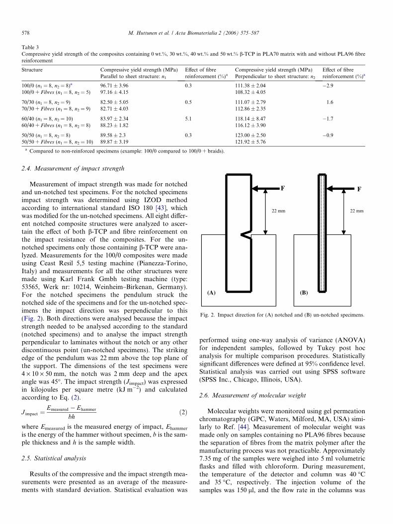
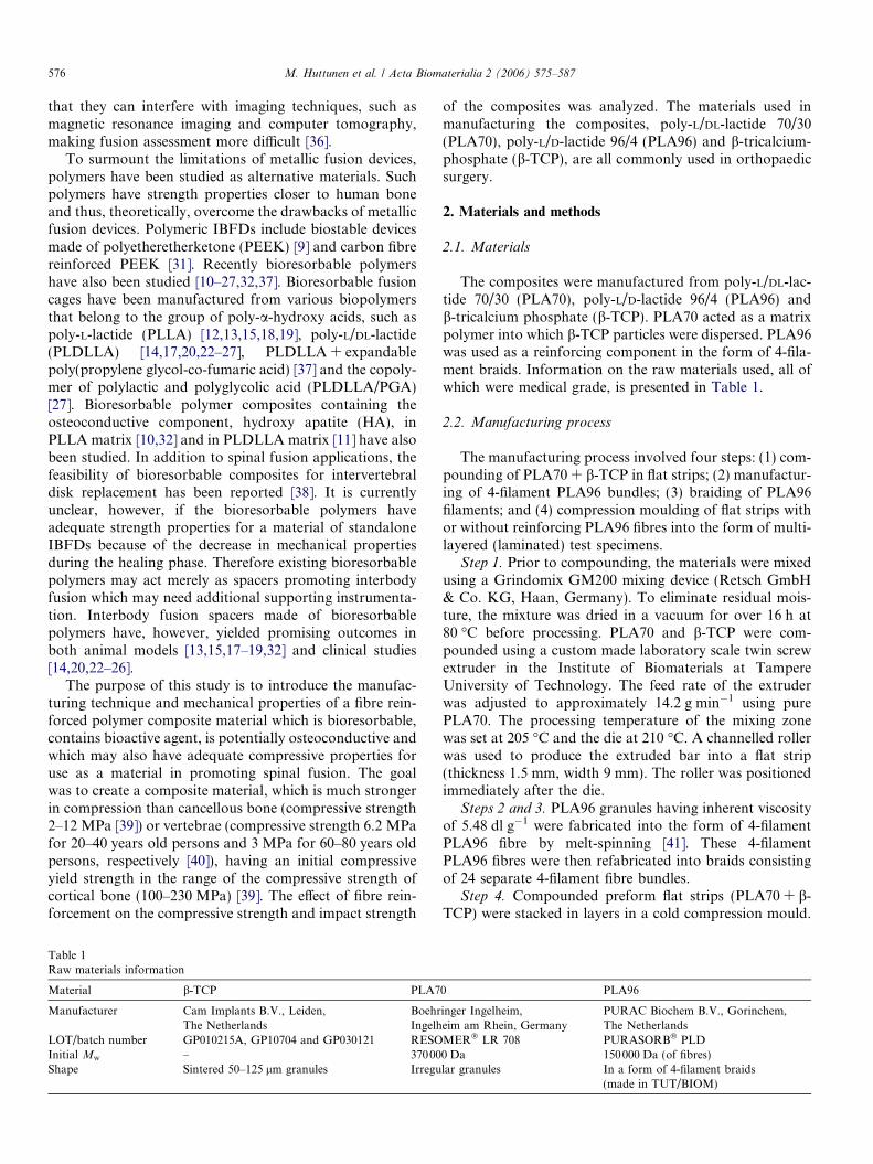
Table 3Compressive yield strength of the composites containing 0 wt.%, 30 wt.%, 40 wt.% and 50 wt.% b-TCP in PLA70 matrix with and without PLA96 fibrereinforcement
Structure Compressive yield strength (MPa) Effect of fibrereinforcement (%)a
Compressive yield strength (MPa) Effect of fibrereinforcement (%)aParallel to sheet structure: n1 Perpendicular to sheet structure: n2
100/0 (n1 = 8, n2 = 8)a 96.71 ± 3.96 0.3 111.38 ± 2.04 �2.9100/0 + Fibres (n1 = 8, n2 = 5) 97.16 ± 4.15 108.32 ± 4.05
70/30 (n1 = 8, n2 = 9) 82.50 ± 5.05 0.5 111.07 ± 2.79 1.670/30 + Fibres (n1 = 8, n2 = 9) 82.71 ± 4.03 112.86 ± 2.35
60/40 (n1 = 8, n2 = 10) 83.97 ± 2.34 5.1 118.14 ± 8.47 �1.760/40 + Fibres (n1 = 8, n2 = 8) 88.23 ± 1.82 116.12 ± 3.90
50/50 (n1 = 8, n2 = 8) 89.58 ± 2.3 0.3 123.00 ± 2.50 �0.950/50 + Fibres (n1 = 8, n2 = 10) 89.87 ± 3.19 121.92 ± 5.76
a Compared to non-reinforced specimens (example: 100/0 compared to 100/0 + braids).
F
22 mm 22 mm
F
(B) (A)
Fig. 2. Impact direction for (A) notched and (B) un-notched specimens.
578 M. Huttunen et al. / Acta Biomaterialia 2 (2006) 575–587
2.4. Measurement of impact strength
Measurement of impact strength was made for notchedand un-notched test specimens. For the notched specimensimpact strength was determined using IZOD methodaccording to international standard ISO 180 [43], whichwas modified for the un-notched specimens. All eight differ-ent notched composite structures were analyzed to ascer-tain the effect of both b-TCP and fibre reinforcement onthe impact resistance of the composites. For the un-notched specimens only those containing b-TCP were ana-lyzed. Measurements for the 100/0 composites were madeusing Ceast Resil 5,5 testing machine (Pianezza-Torino,Italy) and measurements for all the other structures weremade using Karl Frank Gmbh testing machine (type:53565, Werk nr: 10214, Weinheim–Birkenan, Germany).For the notched specimens the pendulum struck thenotched side of the specimens and for the un-notched spec-imens the impact direction was perpendicular to this(Fig. 2). Both directions were analysed because the impactstrength needed to be analysed according to the standard(notched specimens) and to analyse the impact strengthperpendicular to laminates without the notch or any otherdiscontinuous point (un-notched specimens). The strikingedge of the pendulum was 22 mm above the top plane ofthe support. The dimensions of the test specimens were4 · 10 · 50 mm, the notch was 2 mm deep and the apexangle was 45�. The impact strength (Jimpact) was expressedin kilojoules per square metre (kJ m�2) and calculatedaccording to Eq. (2).
J impact ¼Emeasured � Ehammer
bhð2Þ
where Emeasured is the measured energy of impact, Ehammer
is the energy of the hammer without specimen, b is the sam-ple thickness and h is the sample width.
2.5. Statistical analysis
Results of the compressive and the impact strength mea-surements were presented as an average of the measure-ments with standard deviation. Statistical evaluation was
performed using one-way analysis of variance (ANOVA)for independent samples, followed by Tukey post hocanalysis for multiple comparison procedures. Statisticallysignificant differences were defined at 95% confidence level.Statistical analysis was carried out using SPSS software(SPSS Inc., Chicago, Illinois, USA).
2.6. Measurement of molecular weight
Molecular weights were monitored using gel permeationchromatography (GPC, Waters, Milford, MA, USA) simi-larly to Ref. [44]. Measurement of molecular weight wasmade only on samples containing no PLA96 fibres becausethe separation of fibres from the matrix polymer after themanufacturing process was not practicable. Approximately7.35 mg of the samples were weighed into 5 ml volumetricflasks and filled with chloroform. During measurement,the temperature of the detector and column was 40 �Cand 35 �C, respectively. The injection volume of thesamples was 150 ll, and the flow rate in the columns was
M. Huttunen et al. / Acta Biomaterialia 2 (2006) 575–587 579
1 ml min�1. Chloroform was also used as an eluent. Nar-row polystyrene standards were used as references for themeasurements. Results were expressed as an average oftwo parallel injections of the same specimens. Samples con-taining b-TCP were filtered using filter paper beforeanalysis.
2.7. Thermal properties
Thermal properties were monitored by differential scan-ning calorimetry (DSC) using Perkin Elmer PYRIS 1 DSCThermal Analyser (Perkin Elmer, Norwalk, CT, USA) sim-ilarly to Ref. [44]. 6 ± 0.5 mg of the samples was weighedusing Mettler AT621 Deltarange FACT precision scales(Mettler Instrumente AG, Greifenzee, Germany). Indiumwas used as a reference material in the analyses and nitro-gen as a purge gas. The scanning program had two phases.The first phase (A) started at 0 �C and the temperature wasraised 20 �C min�1 up to 220 �C. In the second phase (B)the sample was cooled down to 0 �C at a rate of200 �C min�1 and heated to 220 �C at the same rate as inthe A phase. Glass transition temperatures were measuredfrom the B phase where half Cp extrapolated gives Tg. Noparallel specimens were analyzed.
2.8. Scanning electron microscopy
Scanning electron microscopy (SEM) was used to ana-lyze the surface microstructure of the composites, usingJEOL T100 SEM (JEOL Ltd., Tokyo, Japan) scanningelectron microscope at 15 kV similarly to Ref. [44]. In vitro
specimens were cut to the appropriate size prior to incuba-tion. There were three SEM specimens of each in vitro sam-ple: mould surface, cogged mould surface and machinedsurface. Vacuum dried specimens were fixed on metallicanalysis plates with carbon glue. The specimens were thendried in a vacuum and coated with gold to increase theirelectrical conductivity. Magnifications used were 50·,200· and 1000·.
2.9. In vitro tests for implant prototypes
The in vitro test was performed for the wedge-shapedimplant prototypes with cogged top and bottom surfaceshaving the same laminated sheet structures mentionedabove. Implant prototypes used in vitro experiments weredesigned to mimic the form of the commercial PLIF-implants (PLIF = posterior lumbar interbody fusion). In
vitro follow-up was performed in simulated body fluid(SBF, type K-9 [45]) at an incubation temperature of37 �C. Test specimens were closed into separate test tubeswhich were filled with SBF.
Four implant prototypes were studied: 75/25, 75/25 + Fibres, 50/50, and 50/50 + Fibres (see Table 2). For50/50 + Fibres, the incubation periods were 1, 6, 12, 18and 24 weeks. For the other compositions (75/25, 75/25 + Fibres, and 50/50), there were only two follow-up
points: 12 and 24 weeks. In addition, non-sterile andgamma-sterilized specimens of each series were analyzedprior to in vitro follow-up. The reason for the omissionof follow-up points for other compositions was the limitedamount of raw materials to be analyzed. No statisticalanalyses were made because of the limited number of par-allel test specimens (n = 2). For the SEM specimens of eachseries incubation times were 6, 12, 18 and 24 weeks. Dimen-sions of SEM specimens were �2 · 2 · 2 mm3. The SBFsolution was changed every second week. The ratio ofSBF solution and amount of the samples was approxi-mately 50 ml (SBF)/�1.4 cm3 (sample) which is in accor-dance with Ref. [46], which states that the volume ofincubation media should be at least 20 times that of thespecimen.
During hydrolysis, the pH of the solution was measuredevery second week using a Mettler Toledo MP225 pHmeter (Mettler-Toledo GmbH, Schwerzenbach, Switzer-land). The pH was measured from the incubation mediacontaining test specimens.
Changes in molecular weights, thermal properties andsurface morphology were monitored according to incuba-tion times using the methodology outlined above.
3. Results
3.1. Compressive tests
Compressive yield strength was measured in two direc-tions: parallel to and perpendicular to the sheet (laminar)structure of the composites. The effect of b-TCP on thecompressive yield strength was dependent on the directionof the measurements and demonstrated the anisotropicbehaviour of the laminar composites. Fibre reinforcementhad no significant effect on compressive yield strength oneither of the directions analyzed (p < 0.05). Fig. 3a and bpresent the typical testing curves for 100/0 and 50/50 inboth directions analyzed with clearly visible yield points.Compression modulus was not determined, but as anexample, the linear regression with R2 values are shownin Fig. 3 for 100/0 and 50/50 in both directions. The mea-sured compressive yield strengths for each structure, withthe exact number of test specimens, are summarized toTable 3.
3.1.1. Parallel to sheet structureThe composites containing b-TCP had lower compres-
sive yield strength than the plain (0 wt.% b-TCP) specimens(p < 0.05), both with and without reinforcing fibres.Increasing the amount of b-TCP, however, increased thecompressive yield strength, being significant only whencomparing 70/30 and 60/40 to 50/50 (p < 0.05) and whencomparing 70/30 + Fibres to 50/50 + Fibres (p < 0.05).Though a slight compressive strength increasing effectcould be seen on every composition (0.3–5.1%) fibre rein-forcement had no significant effect on the compressiveyield strength of any structures (p < 0.05). The weakest

y = 7157.7x - 811.12R2 = 0.9979
y = 5792.1x - 508.35R2 = 0.9987
0
1000
2000
3000
4000
5000
6000
0 0.5 1 1.52 2.5
3.5
Compression (mm)
Lo
ad (
N)
Parallel: 50/50 load-deformation curveParallel: 100/0 load-deformation curveLinear (Slope 50/50: On therange 1000-2000N)Linear (Slope 100/0: On therenge 1000-2000kN)
50/50: Load at Yield = 3950 NF
F
(A)
100/0: Load at Yield = 4590 N
y = 14948x - 12170R2 = 0.9984
y = 13669x - 7612R2 = 0.9992
0
2000
4000
6000
8000
10000
12000
14000
16000
18000
20000
22000
24000
26000
28000
30000
0 0.5 1 1.5 2 2.5 3
Compression (mm)
Lo
ad (
N)
Perpendicular: 50/50 load-deformation curvePerpendicular: 100/0 load-deformation curveLinear (Slope 50/50: On therange 5000-10000N)Linear (Slope 100/0: On therange 5000-10000N)
F
F
50/50: Load at Yield = 12050 N
(B)
100/0: Load at Yield = 11330 N
Fig. 3. Compressive load–deformation curves with yield points and linear regression for slope determination at linear region (A) parallel and (B)perpendicular to composites sheet structure.
580 M. Huttunen et al. / Acta Biomaterialia 2 (2006) 575–587
specimens (70/30) demonstrated compressive yield strengthof 82.5 ± 5.05 MPa, while the strongest specimens (100/0 +Fibres) had a compressive yield strength of 97.16 ±4.15 MPa (Table 3).
3.1.2. Perpendicular to sheet structure
The addition of b-TCP increased the compressive yieldstrength compared to the plain specimens (0 wt.% b-TCP)and as the b-TCP content increased so too did the com-pressive yield strength. This was, however, statistically sig-nificant only when comparing plain specimens to 50 wt.%b-TCP containing structures and the behaviour was similarfor both fibre reinforced and non-reinforced specimens(p < 0.05). The compressive strength increasing effect ofb-TCP could also be seen when comparing specimens con-taining different amounts of b-TCP, being significant onlywhen comparing 70/30 to 60/40 and 50/50 (p < 0.05) andwhen comparing 70/30 + Fibres to 50/50 + Fibres (p <
0.05). Fibre reinforcement had no statistically significanteffect on compressive yield strength of any of the analyzedstructures (p < 0.05) though slight differences could be seen(�2.9% � (+1.6%)). The weakest specimens (100/0 + Fibres) demonstrated a compressive yield strength of108.32 ± 4.05 MPa while the strongest (50/50) had a com-pressive yield strength of 123.00 ± 2.50 MPa (Table 3).
3.2. Impact strength
The results of the impact strength measurements withthe exact number of test specimens for the notched (parallelto sheet structure) and un-notched (perpendicular to sheetstructure) are summarized in Table 4.
3.2.1. Notched specimensFor the non-reinforced specimens the impact strength
decreased as the b-TCP content increased, but the decrease

Table 4Impact strength of materials
Structure Impact strength (kJ/m2) Effect of fibrereinforcement:Percentage increaseb (%)
Impact strength (kJ/m2) Effect of fibrereinforcement:Percentage increaseb (%)
Notched specimens(parallel to sheet structure): n1
aUn-notched specimens(perpendicular tosheet structure): n2
100/0 (n1 = 5) 2.50 ± 0.44 127.1 NMc NM100/0 + Fibres (n1 = 7) 5.69 ± 0.66 NM
70/30 (n1 = 10, n2 = 10) 2.29 ± 0.30 215.8 8.00 ± 1.13 64.470/30 + Fibres (n1 = 10, n2 = 10) 7.22 ± 0.93 13.15 ± 2.79
60/40 (n1 = 10, n2 = 10) 2.18 ± 0.45 182.7 6.08 ± 0.7 64.760/40 + Fibres (n1 = 10, n2 = 10) 6.15 ± 1.45 10.01 ± 1.58
50/50 (n1 = 10, n2 = 10) 2.04 ± 0.59 205.1 4.67 ± 0.47 64.950/50 + Fibres (n1 = 10, n2 = 10) 6.23 ± 0.97 7.69 ± 0.95
a Measurement done according to Standard ISO 180 [43].b Compared to non-reinforced specimens (example: 100/0 compared to 100/0 + braids).c Not measured.
M. Huttunen et al. / Acta Biomaterialia 2 (2006) 575–587 581
was statistically insignificant (p < 0.05). Fibre reinforce-ment increased the impact strength of all structures signif-icantly (p < 0.05) being 127.1–215.8% depending on theb-TCP content. For fibre reinforced specimens the impactstrength of every structure containing b-TCP was on aver-age greater than that of specimens having a matrix com-posed of plain PLA70, but the increase was significantonly when comparing 100/0 + Fibres to 70/30 + Fibres(p < 0.05). The reinforcing effect of the fibres was about127% for 100/0, 216% for 70/30, 183% for 60/40 and205% for 50/50. The higher percentage increase for b-TCP containing fibre reinforced specimens may beexplained by the lower values for the non-reinforced b-TCP containing specimens compared to plain structures,by relatively large standard deviations and by the limitednumber of test specimens (n = 5 for 100/0 and n = 7 for100/0 + Fibres). Although measurements for 100/0 weremade using a different testing machine than for the othercompositions, this does not explain the reason for a lowerpercentage increase of fibre reinforcement since the mea-surements for 100/0 + Fibres were made using same testingequipment as for the other compositions.
3.2.2. Un-notched specimensAs Table 4 shows, the fibre reinforcement significantly
increased impact strength of the un-notched specimensanalyzed perpendicular to laminates (p < 0.05), beingapproximately 65% for each composition analysed(p < 0.05). It can also be seen that the impact strengthdecreased as the b-TCP content increased (p < 0.05). Forthe non-reinforced samples this decrease was significantwhen comparing 70/30 to 50/50 (p < 0.05), nearly signifi-cant when comparing 70/30 to 60/40 (p = 0.060) and insig-nificant when comparing 60/40 to 50/50 (p = 0.295). Forfibre reinforced specimens this decrease was significant inall cases (p < 0.05). In contrast to the notched specimens,the trend was similar for both non-reinforced and fibrereinforced specimens.
3.3. In vitro: compressive strength
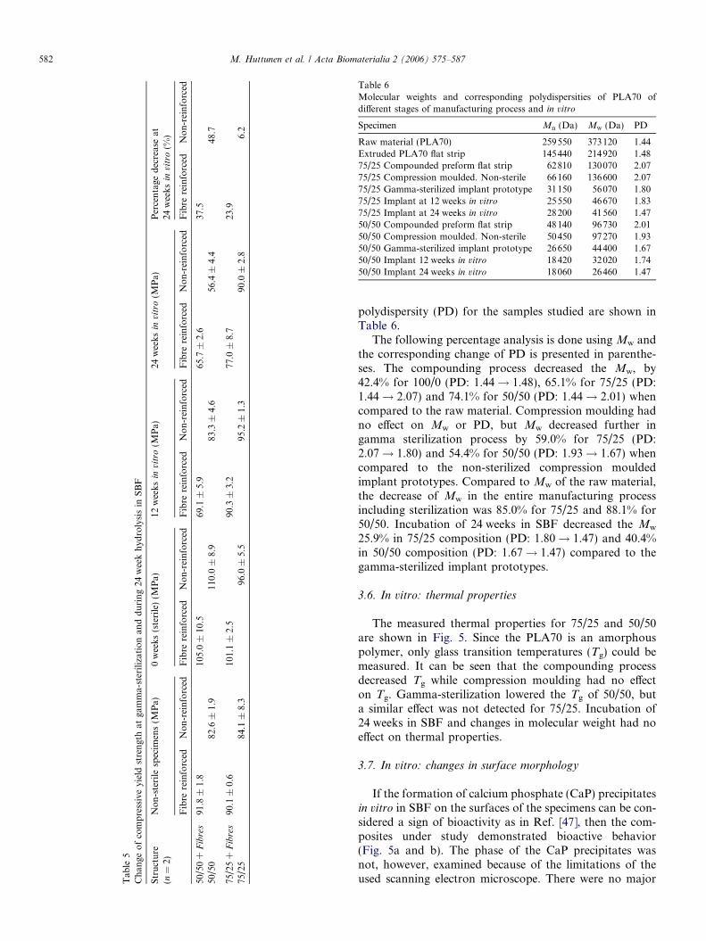
Changes in compressive strength of implant prototypesduring in vitro follow up are presented in Table 5.Gamma-sterilization increased the compressive yieldstrength of all the compositions studied. Twenty five per-centage b-TCP containing composites retained compres-sive strength in hydrolysis better than 50% b-TCPcontaining specimens. After 12 week incubation in SBFthe strongest specimens had lost only 1% of their initialcompressive strength (75/25), while the weakest (50/50 + Fibres) had lost 34% of their initial compressivestrength when compared to their initial values. After24 weeks incubation the decrease of compressive strengthwas 37.5% for 50/50 + Fibres, 48.7% for 50/50, 23.9% for75/25 + Fibres and 6.2% for 75/25 when compared to ini-tial values. The weakest implant prototypes (50/50) hadcompressive strength of 56.4 ± 4.4 MPa (51.3% of the ini-tial value) and the strongest prototypes (75/25) compres-sive strength of 90.0 ± 2.8 MPa (93.8% of the initialvalue) after 24 weeks incubation. The effect of fibre rein-forcement on in vitro follow up was dependent onb-TCP content. During the 24 week follow up the fibrereinforced implant prototypes containing 50 wt.% b-TCPretained their strength better than non-reinforced speci-mens. For 25 wt.% b-TCP containing specimens thebehaviour was the opposite.
3.4. In vitro: pH
No marked changes in pH were detected during24 weeks incubation in SBF. The pH remained near 7.4during the follow-up ranging from 7.32 to 7.62.
3.5. In vitro: measurement of molecular weight
The measured number average molecular weight (Mn),weight average molecular weight (Mw) and corresponding
Tab
le5
Ch
ange
of
com
pre
ssiv
eyi
eld
stre
ngt
hat
gam
ma-
ster
iliz
atio
nan
dd
uri
ng
24w
eek
hyd
roly
sis
inS
BF
Str
uct
ure
(n=
2)N
on
-ste
rile
spec
imen
s(M
Pa)
0w
eek
s(s
teri
le)
(MP
a)12
wee
ks
invi
tro
(MP
a)24
wee
ks
invi
tro
(MP
a)P
erce
nta
ged
ecre
ase
at24
wee
ks
invi
tro
(%)
Fib
rere
info
rced
No
n-r
ein
forc
edF
ibre
rein
forc
edN
on
-rei
nfo
rced
Fib
rere
info
rced
No
n-r
ein
forc
edF
ibre
rein
forc
edN
on
-rei
nfo
rced
Fib
rere
info
rced
No
n-r
ein
forc
ed
50/5
0+
Fib
res
91.8
±1.
810
5.0
±10
.569
.1±
5.9
65.7
±2.
637
.550
/50
82.6
±1.
911
0.0
±8.
983
.3±
4.6
56.4
±4.
448
.7
75/2
5+
Fib
res
90.1
±0.
610
1.1
±2.
590
.3±
3.2
77.0
±8.
723
.975
/25
84.1
±8.
396
.0±
5.5
95.2
±1.
390
.0±
2.8
6.2
Table 6Molecular weights and corresponding polydispersities of PLA70 ofdifferent stages of manufacturing process and in vitro
Specimen Mn (Da) Mw (Da) PD
Raw material (PLA70) 259550 373120 1.44Extruded PLA70 flat strip 145440 214920 1.4875/25 Compounded preform flat strip 62810 130070 2.0775/25 Compression moulded. Non-sterile 66160 136600 2.0775/25 Gamma-sterilized implant prototype 31150 56070 1.8075/25 Implant at 12 weeks in vitro 25550 46670 1.8375/25 Implant at 24 weeks in vitro 28200 41560 1.4750/50 Compounded preform flat strip 48140 96730 2.0150/50 Compression moulded. Non-sterile 50450 97270 1.9350/50 Gamma-sterilized implant prototype 26650 44400 1.6750/50 Implant 12 weeks in vitro 18420 32020 1.7450/50 Implant 24 weeks in vitro 18060 26460 1.47
582 M. Huttunen et al. / Acta Biomaterialia 2 (2006) 575–587
polydispersity (PD) for the samples studied are shown inTable 6.
The following percentage analysis is done using Mw andthe corresponding change of PD is presented in parenthe-ses. The compounding process decreased the Mw, by42.4% for 100/0 (PD: 1.44! 1.48), 65.1% for 75/25 (PD:1.44! 2.07) and 74.1% for 50/50 (PD: 1.44! 2.01) whencompared to the raw material. Compression moulding hadno effect on Mw or PD, but Mw decreased further ingamma sterilization process by 59.0% for 75/25 (PD:2.07! 1.80) and 54.4% for 50/50 (PD: 1.93! 1.67) whencompared to the non-sterilized compression mouldedimplant prototypes. Compared to Mw of the raw material,the decrease of Mw in the entire manufacturing processincluding sterilization was 85.0% for 75/25 and 88.1% for50/50. Incubation of 24 weeks in SBF decreased the Mw
25.9% in 75/25 composition (PD: 1.80! 1.47) and 40.4%in 50/50 composition (PD: 1.67! 1.47) compared to thegamma-sterilized implant prototypes.
3.6. In vitro: thermal properties
The measured thermal properties for 75/25 and 50/50are shown in Fig. 5. Since the PLA70 is an amorphouspolymer, only glass transition temperatures (Tg) could bemeasured. It can be seen that the compounding processdecreased Tg while compression moulding had no effecton Tg. Gamma-sterilization lowered the Tg of 50/50, buta similar effect was not detected for 75/25. Incubation of24 weeks in SBF and changes in molecular weight had noeffect on thermal properties.
3.7. In vitro: changes in surface morphology
If the formation of calcium phosphate (CaP) precipitatesin vitro in SBF on the surfaces of the specimens can be con-sidered a sign of bioactivity as in Ref. [47], then the com-posites under study demonstrated bioactive behavior(Fig. 5a and b). The phase of the CaP precipitates wasnot, however, examined because of the limitations of theused scanning electron microscope. There were no major

Fig. 4. Formation of calcium phosphate precipitation on the surface of the specimen (50/50 + Fibres). (a) Non-hydrolyzed specimen. Partially crumbledb-TCP particle. (b) After 18 weeks incubation. Calcium phosphate precipitation on top of b-TCP granule.
57.4
61.2
59.559.1
56.6 56.8
58.257.8
58.3
58.758.5
54
55
56
57
58
59
60
61
62
Raw materialof PLA70
Extruded flatstrip
Non-sterileimplant
Gamma-sterilizedimplant
12 weeksin vitro
24 weeksin vitro
T g (
°C)
50/50
75/25
Fig. 5. Glass transition temperatures (Tg) at different stages of manufacturing and in vitro.
M. Huttunen et al. / Acta Biomaterialia 2 (2006) 575–587 583
differences in the rate of formation of CaP precipitatesbetween the samples containing 25 and 50 wt.% of b-TCPand reinforcing PLA96 fibres in the composites had noadverse effect on this. At 6 weeks in vitro precipitates hadspread to cover almost all the surfaces of the samples,but there were still areas of no precipitates. Precipitationcould also be seen on the areas containing no b-TCP, suchas on the surfaces of the reinforcing fibres. The formationof CaP layers on the specimens may be considered a phe-nomenon driven by b-TCP, as all the studied in vitro spec-imens contained b-TCP.
4. Discussion
The manufacturing technique presented here seems tobe a feasible method for manufacturing fibre reinforcedbioresorbable composites containing osteoconductive fillerwithout the use of organic solvents in the manufacturingprocess. The entire manufacturing process, includinggamma sterilization, decreased the Mw. The decrease ofMw for in vitro implant prototypes was 85.0% for 75/25composition and 88.1% for 50/50 composition when com-
pared to the raw material. The degradation of the matrixcould also be seen in thermal properties as a decrease ofTg in the compounding process, while compression mould-ing had no effect on Tg. Gamma-sterilization lowered the Tg
of 50/50, but a similar effect was not detected for 75/25. Onthe basis of molecular weight studies it can be assumed thatthe amount of b-TCP in the compounding process corre-lates with the decrease of Mw (the decrease was 42.4% for100/0, 65.1% for 75/25 and 74.1% for 50/50 when comparedto the raw material). No correlation test was made, how-ever. Compression moulding had no effect on molecularweights. Compounding process in twin screw extruder hadno effect on the PD of pure PLA70 (100/0), but did increasethe PD when b-TCP was present (75/25 and 50/50). Thismeans that, as the Mw/Mn ratio increased, the molecularweight distribution was broadened during compoundingprocess when b-TCP was present, indicating greater break-ing down of the PLA70 polymer backbone. This could be aconsequence of the heat absorption of b-TCP during com-pounding. The accelerated decrease of the Mw withincreased b-TCP content indicates the same phenomenon.It can be concluded, therefore, that the amount of b-TCP
584 M. Huttunen et al. / Acta Biomaterialia 2 (2006) 575–587
has an effect on polymer degradation in melt extrusion; thegreater the content, the greater the effect. This may be dueto the heat absorption of b-TCP during the extrusion pro-cess. Another possible explanation is the grinding effect ofb-TCP granules or their effect on the shear flow of the poly-mer melt. The SEM micrographs (Fig. 4a) show that thesintered b-TCP granules partially crumbled during extru-sion, which may indicate the effect of grinding.
The manufactured composites demonstrated anisotropicbehaviour and relatively high compressive yield strengthsof 83–123 MPa, depending on the structure and the direc-tion of the measurements (82.5 ± 5.1 MPa–97.2 ±4.2 MPa parallel and 108.3 ± 4.1 MPa–123.0 ± 2.5 MPaperpendicular to the laminated sheet structure as presentedin Table 3). When compared to the plain specimens, theaddition of b-TCP increased compressive strength perpen-dicular to and decreased compressive strength parallel tothe laminated structure. Reinforcing PLA96 fibres had nosignificant effect on compressive yield strength of any struc-tures analyzed in either direction (p < 0.05), but PLA96fibre reinforcement substantially increased the impactstrength (p < 0.05). For notched specimens (parallel tosheet structure) this increase was about 127% for 100/0,216% for 70/30, 183% for 60/40 and 205% for 50/50. Forun-notched specimens (perpendicular to sheet structure)the reinforcing effect of the PLA96 fibres was similar inevery composition, being approximately 65%.
Measured initial compressive yield strengths of the stud-ied composites were comparable to those in the literaturefor high molecular weight racemic poly-L/D-lactide (60–100 MPa) [17], for PLLA composites with differentamounts of HA (106.7 ± 3.7 MPa–123.5 ± 2.7 MPa) [48]and for biologically stabile polymer PEEK Optima119 MPa (equal to 17,255 psi [49]). Compared to the bio-logical counterpart, initial compressive yield strengthsreached the lower range of the compressive strength of cor-tical bone (100–230 MPa [39]). The highest compressiveyield strengths in the current study were found in thenon-reinforced composites containing 50 wt.% b-TCP(123.0 ± 2.5 MPa) measured perpendicular to the lami-nated structure while the value for 50/50 + Fibres wasslightly lower (121.9 ± 5.8 MPa). These values are slightlyhigher than previously reported for PLLA compositescontaining 50 wt.% HA (115.3 ± 3.9 MPa) [48]. When pre-sented in Newton scale, the composites in the presentstudy could withstand compressive forces 3.2–4.7 kNparallel (A = 40 mm2) and 10.7–12.4 kN perpendicular(A = 100 mm2) to sheet structure, depending on composi-tion. For comparison, a human cervical intervertebral disccan withstand 2 kN of compressive force, a thoracic 2–4 kN, and a lumbar 4.5–8.3 kN, before breakage [50] (upto 11 MPa [40]). A spinal motion segment can withstandup to 3–11 kN of compressive loading before failure [40]and compressive loads occurring in the spine during nor-mal daily activity range from 400 N in motionless stanceto 7 kN in heavy lifting [50,51]. The ‘‘gold standard’’ inspinal fusion, tricortical bone autografts harvested from
the iliac crest, has compressive strength of 4.4 ± 1.5 kN(equals to 7 MPa when measured in paired analysis incadaver spine and calculated according to information pro-vided in Ref. [52]). Bone autografts have, however, uniqueproperties such as osteoconductivity, osteoinductivity andosteogenic potential, none of which can be reproduced atthe same time by any synthetic materials today. Apart fromthis, according to the mechanical comparison presentedabove, the studied composites may have adequate initialcompressive yield strength for use as material for spacerspromoting spinal fusion.
The in vitro test was performed for the wedge-shapedimplant prototypes. An interesting finding was that thoughgamma irradiation decreased molecular weight substan-tially, compression yield strength increased. Aftergamma-sterilization, the initial compressive yield strengthsof implant prototypes were 96–110 MPa (equal to 16.8–19.3 kN) depending on composition. These are comparableto the compressive strengths reported by Cornwall et al.(97 MPa [53]) and Kuklo et al. (100 MPa [22]) for poly-L/DL-lactide spinal fusion cages. In vitro follow up in SBFrevealed that the strength retention behaviour was depen-dent on composite b-TCP content; 25% b-TCP containingcomposites retained compressive strength better than 50%b-TCP containing specimens (Table 5). After the 24 weeksincubation in SBF the weakest implant prototypes of thepresent study (50/50) demonstrated compressive strengthof 56.4 ± 4.4 MPa (equals 10.6 kN) which was 51.3% ofinitial value. 50/50 + Fibres could however retain theirstrength slightly better, being 65.7 ± 2.8 MPa (62.5% of ini-tial value). Behaviour of 25 wt.% b-TCP containingimplant prototypes was, however, the opposite, as 75/25had compression strength of 90.0 ± 2.8 MPa (93.8% of ini-tial value) and 75/25 + Fibres had compression strength of77.0 ± 8.7 MPa (76.1% of initial value) after the 24 weekshydrolysis. The low number of parallel test specimens(n = 2) may explain the difference between the behaviourof the fibre reinforced specimens containing 25 wt.% and50 wt.% b-TCP. The incubation of 24 weeks in SBFdecreased the Mw 25.9% for 75/25 composition and40.4% for 50/50 composition compared to the gamma-ster-ilized implant prototypes. The greater decrease of Mw
in vitro explains the greater drop in compression strengthfor 50/50. The higher initial Mw of 75/25 may also affectthe slower decrease in compressive strength. The explana-tion for the greater decrease in Mw with greater b-TCPcontent may be that there were more free, non-embedded,b-TCP granules on the surfaces of 50/50 specimens than onthe surfaces of 75/25 specimens and therefore the absorp-tion of incubation media inside the specimens wasenhanced via b-TCP-matrix interfaces. This may explainthe increase in the rate of degradation. After 24 weeks incu-bation the PDs of the specimens containing b-TCP weremuch the same as the PD of the raw material. pH of theincubation media (SBF) remained near 7.4 during the fol-low-up, which may be a consequence of the pH bufferingeffect of b-TCP. Similar behaviour in pH has been seen

M. Huttunen et al. / Acta Biomaterialia 2 (2006) 575–587 585
to continue for at least 52 weeks in further studies for sim-ilar composites using phosphate buffer saline (PBS) as anincubation media [54].
Though the compression strength retention in 24 weekhydrolysis test was about 50% in the worst case, the com-pressive strengths of the studied implant prototypes werestill relatively high (56.4 ± 4.4–90.0 ± 2.8 MPa dependingon composition). Such levels of strength would withstandhigher compressive loads than tricortical iliac bone auto-grafts and higher compressive forces than occur duringnormal daily activity and also withstand similar compres-sive loads as the spinal motion segment in failure.
Further studies into the composites made up of similarmaterials to those in the present study (50/50 with andwithout fibre reinforcement) has shown, however, that sim-ilar composites can retain up to 50% of their initial com-pressive strength up to 40 weeks in vitro when measuredperpendicular to the laminated structure. The weakestspecimens had compressive strength of 12 MPa (equals to2.45 ± 0.02 kN) even after 52 week in vitro in phosphatebuffer saline (PBS) [54].
The observed decrease in compressive strength duringin vitro follow-up may, however, be an advantage of thestudied composites. Van Dijk et al. have reported thatthe strength decrease of a PLLA fusion device in vivo dur-ing the healing phase seems to be an advantage as the loadsare transferred to remodelling bone gradually when thecage loses it mechanical properties [19]. This, however,has to be confirmed by further study.
Theoretically, safety at the implantation site may beenhanced since the studied composite structures containedreinforcing fibres which degrade at a slower rate than thematrix. This may minimize the risk of implant fragmenta-tion and migration of possible fragments which can ariseif the implant fails/collapses at the implantation site.Though such behaviour was not examined in this study,and therefore provides no direct experimental evidence,the previously published study [44], where PLA96 fibresin the composite structure degraded at a slower rate thanPLA70 matrix, may support this speculation.
A limitation of this study is that the results must be sup-ported by additional mechanical tests described in ASTMF2077-03 which is designed for intervertebral fusiondevices [55] and by in vivo studies before clinical trials.Though the initial compressive and impact properties weretested according to standards and had an adequate numberof parallel test specimens, the higher amount of test speci-mens would naturally yield more accurate statistical con-clusions. In addition to tests made in this study, the staticand dynamic tests described in Ref. [55] have to be madebefore the safety of the proposed composites can beensured. Another limitation of this study is the low numberof parallel implant prototypes in in vitro follow-up (n = 2),which may affect the results. As the degradation may pro-gress faster in vivo than in vitro, the strength retentionbehavior of the developed composites has to be supportedby in vivo model. The results have to be compared to the
time-scale of healing in spinal fusion (complete healingfrom 6 months to 1 year) to determine if the compositescan retain their strength properties over an adequate periodof time until the remodeled bone can withstand compres-sive loading at the fusion site. The bone-bonding abilityof formatted CaP-precipitation also has to be supportedby histological studies in vivo before the osteoconductivityof manufactured composites is ensured.
5. Conclusions
The laminar composites in this study demonstratedanisotropic behaviour, as the compressive yield strengthwas higher when analyzed perpendicular to the laminatesthan in a parallel direction. Parallel to the laminates, theaddition of b-TCP granules decreased compressive yieldstrength. By increasing the b-TCP content, compressivestrength also increased, but remained lower than that ofthe plain structures. Perpendicular to laminates, the addi-tion of b-TCP increased the compressive yield strengthcompared to the plain specimens and as the b-TCP contentincreased so too did the compressive yield strength. Fibrereinforcement had no significant effect on compressive yieldstrength, but did increase impact strength substantially. Theinitial compressive yield strengths of the studied compositeswere in the lower range of cortical bone, being equal orgreater than values reported in other studies for PEEKOptima, plain poly-a-hydroxyl-acids and their compositeswith hydroxy apatite. The amount of b-TCP in the compos-ites had an effect on strength retention behaviour in vitro, asimplant prototypes with 50 wt.% b-TCP content did notretain their compressive strength as well as composites with25 wt.% b-TCP. Formation of calcium phosphate precipita-tions on the surfaces of specimens was observed and the pHof incubation media remained near 7.4 during the follow up.
The results of this study are encouraging, though furtherstatic and dynamic tests as well as in vivo studies are neededbefore clinical trials. The material developed here may alsohave use as a bone substitute or as a material for bone fix-ation devices, such as plates, pins, screws, etc., in applica-tions where high strength is required.
Acknowledgements
Research funding from the Technology DevelopmentCentre in Finland (TEKES) and the Academy of Finland(Centre of Excellence 40056/04) is greatly appreciated. Thisstudy was in the scope of European Commission project(EXPERTISSUES Project NMP3-CT-2004-500283).
References
[1] Bao Q-B, McCullen G, Higham PA, Dumbleton JH, Yuan HA. Theartificial disc: theory, design and materials. Biomaterials 1996;17:1157–67.
[2] Hart BL, Deyo RA, Cherkin DC. Physician office visits for low backpain. Spine 1995;20:11–9.

586 M. Huttunen et al. / Acta Biomaterialia 2 (2006) 575–587
[3] Biomedical materials. May 2003:2–3.[4] MedPro Month. Volume XII March 2002;3:10–12.[5] Lowe TG. Degenerative disc disease and low back pain. Available
from: http://www.spineuniverse.com/displayarticle.php/article242.html (05272005).
[6] Sasso RC. Screws, Cages or Both? Available from: http://www.spine-universe.com/displayarticle.php/article1363.html (05272005).
[7] Martz EO, Goel VK, Pope MH, Park JB. Materials and designof spinal implants – a review. J Biomed Mater Res 1997;38:267–88.
[8] Zevgardis D, Thome C, Krauss JK. Prospective controlled study oftitanium cage fusion compared with iliac crest autograft fusion inanterior cervical discectomy. Neurosurg Focus 2002;12(1). Article 2.
[9] Biomedical Materials. October 2001:2.[10] Shikinami Y, Okuno M. Mechanical evaluation of novel interbody
fusion cages made of bioactive, resorbable composites. Biomaterials2003;24:3161–70.
[11] Khodadadyan-Klostermann C, Kandziora R, Schnake KJ, Lewand-rowski KU, Wise D, Weiler A. Mechanischer Verleich Biodegradier-berer Intervertebraler Lumbaler Cages. Der Chirurg 2001;72(12):1431–8.
[12] Van Dijk M, Smit TH, Arnoe MF, Burger EH, Wuisman PI. The useof poly-L-lactic acid in lumbar interbody cages: design and biome-chanical evaluation in vitro. Eur Spine J 2003;12(1):34–40.
[13] Van Dijk M, Smit TH, Arnoe MF, Burger EH, Wuisman PI.Bioabsorbable poly-L-lactic acid cages for lumbar interbody fusion:three year follow-up radiographic, histologic, and histomorphometricanalysis in goats. Spine 2002;27(23):2706–14.
[14] Austin RC, Branch CL, Alexander JT. Novel bioabsorbable inter-body fusion spacer-assisted fusion for correction of spinal deformity.Neurosurg Focus 2003;14(1). Article 11.
[15] Van Dijk M, Tunc DC, Smit TH, Higham P, Burger EH, WuismanPIJM. In vitro and in vivo degradation of bioabsorbable PLLA spinalfusion cages. J Biomed Mater Res 2002;63(6):752–9.
[16] Vaccaro AR, Madigan L. Spinal applications of bioabsorbableimplants. J Neurosurg 2002;97(Suppl 4):407–12.
[17] Toth JM, Estes BT, Wang M, Seim 3rd HB, Scifert JL, Turner AS,et al. Evaluation of 70/30 poly(L-lactide-co-D,L-lactide) for use as aresorbable interbody fusion cage. J Neurosurg 2002;97(Suppl 4):423–32.
[18] Wuisman PIJM, van Dijk M, Smit TH. Resorbable cages for spinalfusion: an experimental goat model. J Neurosurg 2002;97(Suppl 4):433–9.
[19] Van Dijk M, Smit TH, Sugihara S, Burger EH, Wuisman PI. Theeffect of cage stiffness on the rate of lumbar interbody fusion: anin vivo model using poly(L-lactic acid) and titanium cages. Spine2002;27(7):682–8.
[20] Lowe TG, Coe JD. Resorbable polymer implants in unilateraltransforaminal lumbar interbody fusion. J Neurosurg 2002;97(Suppl 4):464–7.
[21] Alexander JT, Branch Jr CL, Subach BR, Haid Jr RW. Applicationsof a resorbable interbody spacer in posterior lumbar interbody fusion.J Neurosurg 2002;97(Suppl 4):468–72.
[22] Kuklo TR, Rosner MK, Polly DW. Computerized tomographyevaluation of a resorbable implant after transforaminal lumbarinterbody fusion. Neurosurg Focus 2004;16(3). Article 10.
[23] Couture DE, Branch Jr CL. Posterior lumbar interbody fusion withbioabsorbable spacers and local autograft in a series of 27 patients.Neurosurg Focus 2004;16(3). Article 8.
[24] Lanman TH, Hopkins TJ. Early findings in a pilot study of anteriorcervical interbody fusion in which recombinant human bone mor-phogenetic protein-2 was used with poly(L-lactide-co-D,L-lactide)bioabsorbable implants. Neurosurg Focus 2004;16(3). Article 6.
[25] Lanman TH, Hopkins TJ. Lumbar interbody fusion after treatmentwith recombinant human bone morphogenetic protein-2 added to70:30 poly(L-lactide-co-D,L-lactide) bioresorbable implants. Neuro-surg Focus 2004;16(3). Article 9.
[26] Coe JD. Instrumented transforaminal lumbar interbody fusion withbioabsorbable polymer implants and iliac crest autograft. NeurosurgFocus 2004;16(3). Article 11.
[27] Lippman CR, Hajjar M, Abshire B, Martin G, Engelman RW, CahillDV. Cervical spine fusion with bioabsorbable cages. NeurosurgFocus 2004;16(3). Article 4.
[28] Bruneau M, Nisolle J-F, Gilliard C, Gustin T. Anterior cervicalinterbody fusion with hydroxyapatite graft and plate system. Neu-rosurg Focus 2001;10(4). Article 8.
[29] Thalgott JS, Giuffre JM, Fritts K, Timlin M, Klezl Z. Instrumentedposterolateral lumbar fusion using coralline hydroxy apatite with orwithout demineralized bone matrix, as an adjunct to autogenousbone. Spine J 2001;1(2):131–7.
[30] Glazer PA, Spencer UM, Alkalay RN, Schwardt J. In vivo evaluationof calcium sulfate as a bone graft substitute for spinal fusion. Spine J2001;1(6):395–401.
[31] Salame K, Ouaknine GER, Razon N, Rochkind S. The use of carbonfibre cages in anterior cervical interbody fusion, report of 100 cases.Neurosurg Focus 2002;12(1). Article 1.
[32] Hojo Y, Kotani Y, Ito M, Abumi K, Kadosawa T, Shikinami Y,et al. A biomechanical and histological evaluation of a bioresorbablelumbar interbody fusion cage. Biomaterials 2005;26(15):2643–51.
[33] Janssen ME, Lam C, Beckham R. Outcomes of allogenic cages inanterior and posterior lumbar interbody fusion. In: Gunzburg R,Szpalski M, Passuti N, Aebi M, editors. The use of bone substitutes inspine surgery, a state of art review. Berlin, Germany: Springer-Verlag; 2002. p. 74–84.
[34] Gogolewski S. Bioresorbable polymers in trauma and bone surgery.Injury 2000;31:28–32.
[35] Blumenthal SL, Ohnmeiss DD. Contemporary concepts in spine care:intervertebral cages for degenerative spinal diseases. Spine J 2003;3(4):301–9.
[36] Burkus JK, Foley K, Haid R, LeHeuc J-C. Surgical interbodyresearch group – radiographic assessment of interbody fusion devices:fusion criteria for anterior lumbar interbody surgery. NeurosurgFocus 2001;10(4). Article 11.
[37] Kandziora R, Pflugmacher R, Kleemann R, Duda G, Wise DL,Trantolo DL, et al. Biomechanical analysis of biodegradable inter-body fusion cages augmented with poly(propylene glycol-co-fumaricacid). Spine 2002;27(15):1644–51.
[38] Palmgren T, Ylinen P, Tulamo R-M, Kellomaki M, Tormala P,Rokkanen P. Lumbar intervertebral disc replacement using bioab-sorbable self-reinforced poly-L-lactide full-threaded screws, or cylin-drical implants of polylactide polymers, bioactive glass andpolyactiveTM. Vet Comp Orthop Traumatol 2003;3:138–44.
[39] Hench LL, Wilson J. In: Hench LL, Wilson J, editors. An introductionto bioceramics. Singapore: World Scientific; 1993 [Chapter 1].
[40] Mathey M, Meier C, Luscher P, Mayer J, Wintermantel E, Koch B. Anew intervertebral disc replacing biomaterial: open porous, hydroxy-apatite filled polymethylmethacrylate. Biomed Eng Appl Basis Comm1993;5(3):18–23.
[41] Kellomaki M, Tormala P. Processing of resorbable poly-a-hydroxyacids for use as tissue-engineering scaffolds. Methods in molecularbiology. Biopolymer methods in tissue engineering, vol. 238. Totowa,NJ: Humana Press; 2003. p. 1–10.
[42] ISO 604:2002(E). Plastics—Determination of compressive properties.International Organization of Standardization 1993. p. 1–9.
[43] ISO 180:2000. Plastics—Determination of Izod impact strength.International Organization of Standardization 2000. p. 1–10.
[44] Kellomaki M, Paasimaa S, Tormala P. Pliable polylactide plates forguided bone regeneration: manufacturing and in vitro. Proc InstMech Eng 2000;20(Part H):615–29.
[45] Kokubo T, Kushitani H, Sakka S, Kitsugi T, Yamamuro T. Solutionsable to reproduce in vivo surface-structure changes in bioactive glassceramic A–W. J Biomed Mater Res 1990;24(6):721–34.
[46] US Food and Drug Administration, Guidance document for testingbiodegradable polymer implant devices (Draft), 1996.

M. Huttunen et al. / Acta Biomaterialia 2 (2006) 575–587 587
[47] Kokubo T. A/W Glass–ceramic: processing and properties. In: HenchLL, Wilson J, editors. An introduction to bioceramics. Singa-pore: World Scientific; 1993. p. 75–88 [Chapter 5].
[48] Shikinami Y, Okuno M. Bioresorbable devices made of forgedcomposites of hydroxyapatite (HA) particles and poly-L-lactide(PLLA): Part I. Basic characteristics. Biomaterials 1999;20(9):859–77.
[49] PEEK all, Custom Cutting Technologies Inc., Available from: http://www.cctplastics.com/peekall.html (03142006).
[50] White AA, Panjabi MM. Clinical biomechanics of the spine. 2nded. Philadelphia, PA: Lippincott; 1990.
[51] Nachemson AL, Schultz AB, Berkson MH. Mechanical properties ofhuman lumbar spine motion segments: influence of age, sex, disc leveland degeneration. Spine 1979;4:1–8.
[52] Hoshijima K, Nightingale RW, Yu JR, Richardson WJ, Harper KD,Yamamoto H, et al. Strength and stability of posterior lumbarinterbody fusion. Spine 1997;22(11):1181–8.
[53] Cornwall GB, Thomas KA, McManus AJ, Moser RC, KisselburghC. Compressive strength retention of 70:30 poly(L-lactide-co-D,L-lactide) following real time agening. Society for biomaterials 29thannual meeting transactions. p. 393.
[54] Huttunen M, Kellomaki M, Tormala P, Ashammakhi N. Bioresorb-able fibre reinforced composites for spinal fusion application: in vitro
analysis. Eur Cell Mater 2005;10(Suppl 3):60.[55] ASTM F2077-03 Test methods for intervebral body fusion devices,
Conshohocken, PA, ASTM International, p. 1–9.