FIBRE OPTIC SYSTEM INSTALLATION MANUAL - AKVA Group Manuals/Camera/UK Fibre Optic … · View of...
34
FIBRE OPTIC SYSTEM INSTALLATION MANUAL Date 12/02/2013 Version 1.0
Transcript of FIBRE OPTIC SYSTEM INSTALLATION MANUAL - AKVA Group Manuals/Camera/UK Fibre Optic … · View of...

FIBRE OPTIC SYSTEM
INSTALLATION MANUAL
Date 12/02/2013
Version 1.0

2
1. Contents 1. Contents ................................................................................................. 2
2. Specific objectives .................................................................................. 3
3. System Overview .................................................................................... 3
3.1 Key Components ........................................................................................ 3
4. Installation on the cage module ............................................................. 6
4.1 Installation of the galvanized pedestals ......................................................... 6
4.2 Mounting the cabinets (MCAP 4 AND 6,Media Converter) ................................. 8
4.3 Ducting the conducting cables on the module. ............................................. 10
4.4 Installing cable organizers. (Video) ............................................................. 13
4.5 Ducting of power and data cables on the module. ......................................... 16
4.6 Power installation on the cages .................................................................. 17
4.7 Installing data cables onto the module. ....................................................... 20
5. Installing the equipment in the control room on the barge .................. 22
5.1 Positioning of the equipment (PC/Media Converter) ...................................... 23
5.2 Installing the power and data cables. (RVK and ETHERNET) ........................... 23
6. Installation from barge to module. ....................................................... 25
6.1 Installation and fixing of the ducted cable from the barge to the module. ........ 25
6.2 Wiring and ducting the power cables from barge to module. .......................... 29
6.2 Connecting the fibre optic and power cables on the barge. ............................ 31
7. Appendices ........................................................................................... 32
7.1 Defining the cabinet positioning on the module. ........................................... 32
7.2 Example connection line diagram ............................................................... 34

3
2. Specific objectives
1. To show the various components of the fibre optic monitoring system and their
correct functioning.
2. To establish a standard mode of installation through the definition of the different
work areas at the farm site.
3. To demonstrate the possible configurations of the distribution components on
different cage modules.
4. To define a standard installation procedure.
3. System Overview
The fibre optic monitoring system was developed in response to the need for a stable e
monitoring system which could produce high quality imaging.
The solution involved the creation of an Ethernet network on the cage module which is
connected to the control room on the barge via a fibre optic cable. The software AKVA
Connect controls the entire system.
3.1 Key Components
The main components of the system are: Media Converter, MCAP 4, AKVA Connect and
fibre optic cable.
Media Converter
The unit can either be installed on the barge or on the cage module itself. Its main
function is to convert signals between two different transmission media, in this case,
Ethernet and fibre optic cables, transforming UTP signals to fibre optics and vice versa.
It can transmit signals up to 2km.
The product is available in two variations:
Media Converter
Media Converter + Switch
MCAP
This unit can be connected to multiple cameras (from 1 up to 8), converting analogue
video signals to digital or H.264 (or JPEG) format. These signals are then transmitted
via an Ethernet network cable to the Media Converter.
The unit is installed on the cage module.

4
FIBRE OPTIC
Optical fibres are widely used in fibre-optic communications as they can send large
amount of data over a long distance, with speeds similar to radio and superior to
conventional cable. An optical fibre is a flexible, transparent fibre made of glass or
plastic, which can transmit light between the two ends of the fibre. The light beam is
kept in the core by total internal reflection. The light source may be laser or LED.
Fibres are used instead of metal wires because signals travel along them with less
loss and they are immune to electromagnetic interference. They are wrapped in
bundles so they can carry images, thus allowing viewing in confined spaces.
The cable used in this type of installation contains the following specs:
Predetermined cable
4 Core Loose Tube
Steel Wire Armoured
50/125 OM2
Multi Mode
LSZH
Conectores SC

5
3.2 SECTIONS/SECTIONAL DIAGRAM.
This diagram shows the different installation Sections available, which will be detailed
in other chapters on this manual.
Installation in the control room
on the barge
Installation on the barge and the cage module
Installation on the cage module

6
4. Installation on the cage module
4.1 Installation of the galvanized pedestals
AX Code Description Qty Unit
103957 PEDESTAL 1.5 MTS TUBE 1 3/4"X2 MM GALV W/INS 1 pc
102000 BOLT 1/2" X 2" GALV. GR.2 3 pc
102084 NUT 1/2" GALV. GR.2 3 pc
101972 LOCK WASHER 1/2" GALV. GR.2 3 pc
101955 WASHER 1/2" GALV. GR.2 3 pc
PEDESTAL 1.5 MTS TUBE 1
3/4"X2 MM GALV W/INS.
BOLT 1/2" X 2" GALV. GR.2
LOCK WASHER 1/2" GALV.
GR.2
WASHER 1/2"
GALV. GR.2
NUT 1/2" GALV. GR.2
7
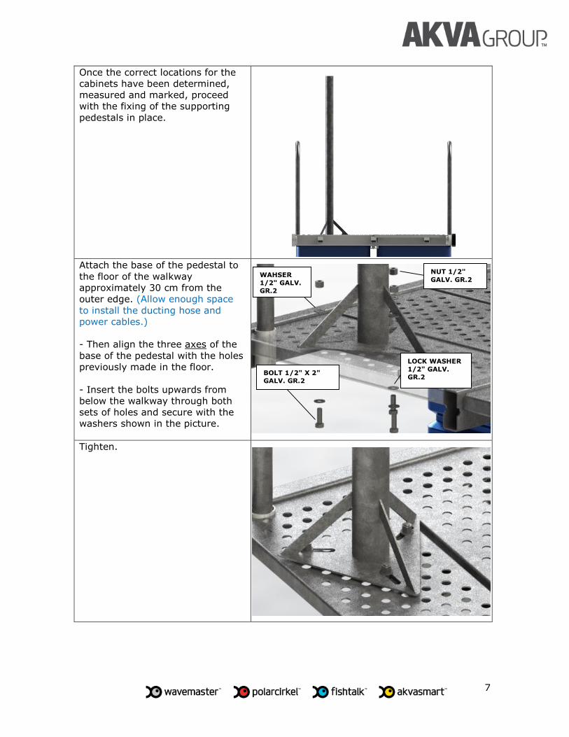
Once the correct locations for the
cabinets have been determined,
measured and marked, proceed
with the fixing of the supporting
pedestals in place.
Attach the base of the pedestal to
the floor of the walkway
approximately 30 cm from the
outer edge. (Allow enough space
to install the ducting hose and
power cables.)
- Then align the three axes of the
base of the pedestal with the holes
previously made in the floor.
- Insert the bolts upwards from
below the walkway through both
sets of holes and secure with the
washers shown in the picture.
Tighten.
BOLT 1/2" X 2"
GALV. GR.2
WAHSER
1/2" GALV.
GR.2
LOCK WASHER
1/2" GALV. GR.2
NUT 1/2"
GALV. GR.2

8
4.2 Mounting the cabinets (MCAP 4 AND 6,Media Converter)
AX Code Description Qty Unit
104742 Media Converter Single 1 pc
104743 MCAP 4 1 pc
104903 MCAP 4 Twin 1 pc
103855 Omega clamp with plate 3x30x380mm 6 pc
MEDIA CONVERTER
MCAP 4
MCAP 6
Omega clamp with plate 3x30x380mm

9
Attach the omega clamps, along with the 3x30x380mm plates, to the rear of the
cabinet. Mount the cabinet on the pedestal using the clamps
and plates. Allow for 50mm pedestal clearance above the top of the cabinet.
50 mm

10
4.3 Ducting the conducting cables on the module.
For component positioning options mentioned above, (see page 33).
AX Code Description Qty Unit
104496 Hose Cover 63 mm 3 x 2,5 - FO 1 pc
100863 HDPE Hoose Hig Density 63 mm thickness 3,6 mm 3 per 4 cages pc
104493 Hose Clamp 1 per pedest. pc
103910 Conduit Flexible 13,5 61747010 1 per clamp pc
103920 Conector recto 18xM20 p/conduit 2 pc
Hose Cover 63 mm
3 x 2,5-FO
HDPE Pipe High Density. 63mm thickness
3,6mm
Hoose Clamp
Conduit 13,5 61747010
Straight Connector 18xM20 for conduit

11
Unroll the high-density, black
HDPE hose (diameter 63cm,
thickness of wall 3.6mm) along the
central walkway of the module
behind the previously installed
pedestals.
Attach a clamp at the beginning of
the hose and fix.

12
Follow the length of the hose and drill
holes at the designated points where each
pedestal will be installed.
- Assemble the clamp.
- Fix the straight connector in place
Do the same at the intended locations for
all the pedestals on the module.

13
4.4 Installing cable organizers. (Video)
Hook Hose
Hose 63mm
AX Code Description Qty Unit
104761 Hook Hose 2 pc
100863 63 mm Hose mt
There are 2 types of hooks - one for 150mm-wide beams and one for 200mm beams.
The length of the hoses should correspond with the width of the walkway

14
The cable organizers must be fitted
to the underside of the walkway
beams. Each organizer comprises
63mm HDPE hose and 2 hooks.
Step by step installation of the
cable organizers. (Pictures)
- The length of the hose measures
the width of the walkway plus 10
cm.

15
View of the video cable organizer
installation from below.
View of the video cable organizer
installation from above.

16
4.5 Ducting of power and data cables on the module.
Ducting the collar to the control
cabinet using a flexible conduit.
Conduit Flexible

17
4.6 Power installation on the cages
The TDP control board (see synonyms below) supplies power to all the control
cabinets installed on the module.
Connections
Take 2 RVK cables from the TDP control board to begin a serial connections to the
other control cabinets on the module.
Start by connecting 1 RVK cable from the TDP control board to the MCAP board on one
side, threading it through the collars and the conduit. (63mm hose)
Then take the second RVK cable from the TDP panel to the MCAP board on the other
side, threading it through the collars and conduit. (63mm hose)
PI MCAP MCAP MEDIA CONVERTER
PI MCAP MCAP MEDIA CONVERTER

18
Then take an RVK cable from the MCAP board to the Media Converter, threading it
through the collars and conduit. (63mm hose)
PI MCAP MCAP MEDIA CONVERTER

19
MCAP
PI
N N
Diagram showing the power network generated on the module.
Media Converter RVK

20
4.7 Installing data cables onto the module.
Connections
Start by connecting an Ethernet Network cable from the Media Converter control panel
to the MCAP panel, threading it through the collars and duct. (63mm hose)
Then take a Network cable from the MCAP cabinet to the next MCAP cabinet threading
it through the collars and duct. (63mm hose)
TDP MCAP MCAP MEDIA CONVERTER
TDP MCAP MCAP MEDIA CONVERTER

21
MCAP
ETHERNET
N
Diagram of the data network generated on the module.
Media Converter

22
5. Installing the equipment in the control room on the barge AX Code Description Qty Unit
100536 PC DELL Optiplex,i3,2Gb Ram(1)MonVid 1VGA/1DP 1 pc
100501 UTP Cable for exterior CAT6 40 mt
100511 RJ45 Conector 2 pc
104457 RJ45 Cover 1 pc
104316 WPRJ-LSR RJ45 IP67 Long Strain Relief 1 pc
100533 LCD 32 " AOC 931-AOC W033 1 pc
100548 Mounting for LCD-Plasma 17"a 37" 1 pc
103736 Media Converter Barge 1 pc
103855 Omega clamp with plate 3x30x380mm 2 pc
104007 Powe Strips 1 pc
AKVA Connect License 1
PC,i3,2Gb Ram(1)MonVid 1VGA/1DP
UTP Cable for exterior CAT6
RJ45 Conector
RJ45 Cover
WPRJ-LSR RJ45 IP67
Long Strain Relief
LCD 32 " AOC 931-AOC W033
MEDIA CONVERTER BARGE
Omega Clamp with plate

23
5.1 Positioning of the equipment (PC/Media Converter)
Find the best location for the
equipment on the barge.
The PC must be installed in the
barge control room.
The Barge Media Converter must
be housed in a protected location,
preferably inside.
Installation of the equipment on
the barge.
Begin installing the PC and Barge
Media Converter.
Ducting the cables on the barge.
This varies from installation to
installation, but both the power
and data cables must be ducted.
5.2 Installing the power and data cables. (RVK and ETHERNET)

24
Use an Ethernet cable to connect
the PC to the Media Converter.
Note that the Media Converter
uses 220V electrical power.
Ethernet
220V

25
6. Installation from barge to module.
6.1 Installation and fixing of the ducted cable from the barge to the module.
Add an extra line to the selector
valve or use an existing one to
cable the barge to the module.

26
Drill a hole at the beginning of
the hose to allow for the insertion
of a 65mm polystyrene ball.
Drill a hole through the center of
the ball.
Thread 6 to 8mm of cord/rope
through the hole and tie it off.
(The cord/rope must be 3m
longer than the distance between
the barge and the module.)
Insert the ball into the hole in the
hose.

27
Mount a reel of fiber optic and
RVK cables on the edge of the
module.

28
Then activate the system by
selecting the CSS line to be used
as a duct.
Using the blower, blow the ball
through the duct so the end of
the rope reaches the module.
Untie and remove the ball and
then tie the fibre optic and RVK
cables to the cord.
From the barge, slowly and
steadily pull the cables through
the duct to prevent damaging the
cables.
FIBRE
OPTIC
RVK
29
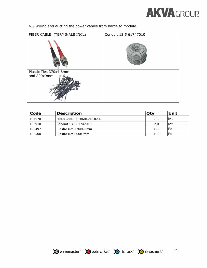
6.2 Wiring and ducting the power cables from barge to module.
FIBER CABLE (TERMINALS INCL)
Conduit 13,5 61747010
Plastic Ties 370x4.8mm
and 800x9mm
Code Description Qty Unit
104678 FIBER CABLE (TERMINALS INCL) 200 Mt
103910 Conduit 13,5 61747010 2,0 Mt
102497 Plastic Ties 370x4.8mm 100 Pc
102500 Plastic Ties 800x9mm 100 Pc

30
Cap the ends of the 90mm hose
using CAPS / CONNECTORS
Duct the cables with flexible
conduit for protection.
Take a fibre optic cable from the
90mm hose and connect it to the
Media Converter.
At the same time run the RVK
cable from the tee, which is at
the connection point of Media
Converter, following the duct
until it reaches the TDP and
connect.
CONDUIT
CONDUIT
RVK

31
6.2 Connecting the fibre optic and power cables on the barge.
Take the fibre optic and RVK
cables.
- Connect the fibre optic cable to
the Media Converter.
- Connect the RVK cable to the
220v power.
RVK
FIBRE
OPTIC
FIBRE
OPTIC
220V

32
Media Converter Module
MCAP 4
TDP sensor JM
MCAP 6
7. Appendices
7.1 Defining the cabinet positioning on the module.
This section defines the location of the cabinets to be installed on the assumption that
the module in question is 30m long.
When installing the system on different sized modules, the following restrictions must
be taken into consideration:
The maximum distance between MCAP and Media Converter must not
exceed 90m. The cable and electrical sizing should be reviewed on a case by case
basis.
Component Symbols.

33
Configurations location of equipment in the module as N. cages.
20 c
ages
30x30
18 c
ages
30x30
16 c
ages
30x30
14 c
ages
30x30
12 c
ages
30x30
10 c
ages
30x30

34
7.2 Example connection line diagram