Fibre Optic Network Design and Installation
30
Information and Technology Group Operational Technology DESIGN STANDARD DS 43-06 Fibre Optic Network Design and Installation VERSION 1 REVISION 1 AUGUST 2020
Transcript of Fibre Optic Network Design and Installation
Information and Technology Group Operational Technology
DESIGN STANDARD DS 43-06
Fibre Optic Network Design and Installation
VERSION 1 REVISION 1 AUGUST 2020

Design Standard No. DS 43-06 Fibre Optic Network Design and Installation
Uncontrolled if Printed Page 2 of 30 Ver 1 Rev 1 © Copyright Water Corporation 2020
FOREWORD
Design Standards are prepared to ensure that the Water Corporation’s staff, consultants and contractors are informed as to the Water Corporation’s design standards and recommended practices. Design standards are intended to promote uniformity so as to simplify design and drafting practice and have as their ultimate objective the provision of safe and functional plant at minimum whole of life cost.
The Water Corporation design standards and recommended practices described in this design standard have evolved over a number of years as a result of design and field experience and these have been investigated and documented.
Deviation, on a particular project, from the design standards and recommended practices may be permitted in special circumstances but only after consultation with and endorsement by the Principal SCADA Engineer in the Water Corporation’s Operational Technology.
Users are invited to forward submissions for continuous improvement to the Principal SCADA Engineer who will consider these for incorporation into future revisions.
Head of Operational Technology
This document is prepared without the assumption of a duty of care by the Water Corporation. The document is not intended to be nor should it be relied on as a substitute for professional engineering design expertise or any other professional advice.
It is the responsibility of the user to ensure they are using the current version of this document.
© Copyright – Water Corporation: This standard and software is copyright. With the exception of use permitted by the Copyright Act 1968, no part may be reproduced without the written permission of the Water Corporation.

Design Standard No. DS 43-06 Fibre Optic Network Design and Installation
Uncontrolled if Printed Page 3 of 30 Ver 1 Rev 1 © Copyright Water Corporation 2020
REVISION STATUS
The revision status of this standard is shown section by section below:
SECT. VER/ REV
DATE PAGES REVISED
REVISION DESCRIPTION (Section, Clause, Sub-Clause)
RVWD. APRV.
All 1/0 23/03/18 All New Version JB JB 3.2 1/1 20/07/20 7,8 Standards references updated JB JB

Design Standard No. DS 43-06 Fibre Optic Network Design and Installation
Uncontrolled if Printed Page 4 of 30 Ver 1 Rev 1 © Copyright Water Corporation 2020
DESIGN STANDARD DS 43-06 Fibre Optic Network Design and Installation
CONTENTS Section Page
1 Introduction ................................................................................................................................... 7
2 Scope ............................................................................................................................................... 7
3 Standards ....................................................................................................................................... 7
3.1 Water Corporation Standards .................................................................................................... 7
3.2 Australian Standards ................................................................................................................... 7
3.3 International Standards .............................................................................................................. 8
4 Abbreviations ................................................................................................................................ 8
5 Mandatory Requirements ............................................................................................................ 8
6 Design ............................................................................................................................................. 9
6.1 Cable Route .................................................................................................................................. 9
6.2 Fibre Network .............................................................................................................................. 9
6.3 Optical Power Budget................................................................................................................ 10
7 Optical Fibre ............................................................................................................................... 10
7.1 General ........................................................................................................................................ 10
7.2 Physical Characteristics ............................................................................................................ 10 7.2.1 Cable Sheath ................................................................................................................................ 10 7.2.2 Loose Tube .................................................................................................................................. 11 7.2.3 Tight Buffered .............................................................................................................................. 11 7.2.4 Pre-terminated Cables .................................................................................................................. 12 7.2.5 Fibre Core .................................................................................................................................... 12
7.2.5.1 Multi-Mode ................................................................................................................... 12 7.2.5.2 Single Mode .................................................................................................................. 13
7.3 Optical Performance ................................................................................................................. 13 7.3.1 Multi-Mode .................................................................................................................................. 13
7.3.1.1 Cable Transmission Performance Specification........................................................... 13 7.3.2 Single Mode ................................................................................................................................. 13
7.3.2.1 Cable Transmission Performance Specification........................................................... 13
8 Installation ................................................................................................................................... 13
8.1 Depth ........................................................................................................................................... 14
8.2 Trenching .................................................................................................................................... 14 8.2.1 Bedding Material ......................................................................................................................... 15 8.2.2 Backfill Material .......................................................................................................................... 15 8.2.3 Barriers ......................................................................................................................................... 15 8.2.4 Separation between Services ....................................................................................................... 15

Design Standard No. DS 43-06 Fibre Optic Network Design and Installation
Uncontrolled if Printed Page 5 of 30 Ver 1 Rev 1 © Copyright Water Corporation 2020
8.3 Directional Boring...................................................................................................................... 15
8.4 Direct Buried .............................................................................................................................. 16
8.5 Conduit........................................................................................................................................ 16 8.5.1 Size ............................................................................................................................................... 16 8.5.2 General Pipe Specifications ......................................................................................................... 16 8.5.3 Fittings ......................................................................................................................................... 17
8.6 Pits ............................................................................................................................................... 17 8.6.1 Pit Materials ................................................................................................................................. 17 8.6.2 Pit Installation .............................................................................................................................. 18
8.7 Fibre Loops ................................................................................................................................. 18
8.8 Cable Entries .............................................................................................................................. 18
8.9 Hauling ........................................................................................................................................ 18 8.9.1 Cable Hauling Equipment ............................................................................................................ 19 8.9.2 Ropes for Hauling ........................................................................................................................ 19 8.9.3 Cable Guides ................................................................................................................................ 19
8.10 Tray/Risers ................................................................................................................................. 19 8.10.1 FiberGuide ................................................................................................................................... 19
8.11 Route Marking ........................................................................................................................... 19
9 Cable Jointing.............................................................................................................................. 20
10 Cable Termination ...................................................................................................................... 20
10.1 FOBOT ....................................................................................................................................... 20
10.2 Connectors and Pigtails ............................................................................................................. 20 10.2.1 Connector Types .......................................................................................................................... 21
10.2.1.1 SC Connector ................................................................................................................ 21 10.2.1.2 FC Connector ................................................................................................................ 21 10.2.1.3 LC Connector ............................................................................................................... 21
10.2.2 Inspection and Cleaning ............................................................................................................... 22
10.3 Patch Leads ................................................................................................................................ 22 10.3.1 Patch Lead Management .............................................................................................................. 22
11 Testing and Commissioning ....................................................................................................... 22
11.1 Competency ................................................................................................................................ 23
11.2 Test Equipment .......................................................................................................................... 23 11.2.1 Power Meter ................................................................................................................................. 23 11.2.2 Stabilised Light Source ................................................................................................................ 23 11.2.3 Optical Time Domain Reflectometer (OTDR) ............................................................................ 23
11.3 Cable Acceptance Measurements ............................................................................................. 23 11.3.1 Insertion Loss ............................................................................................................................... 24 11.3.2 Link Loss ..................................................................................................................................... 24 11.3.3 Connector/Pigtail Loss ................................................................................................................. 25 11.3.4 Splice Loss ................................................................................................................................... 25 11.3.5 Section Loss ................................................................................................................................. 25

Design Standard No. DS 43-06 Fibre Optic Network Design and Installation
Uncontrolled if Printed Page 6 of 30 Ver 1 Rev 1 © Copyright Water Corporation 2020
12 Safety ............................................................................................................................................ 26
12.1 Laser Safety ................................................................................................................................ 26
12.2 Fibre Handling ........................................................................................................................... 26
13 Labelling ...................................................................................................................................... 26
14 Records ......................................................................................................................................... 27
14.1 Drawings ..................................................................................................................................... 27
14.2 Cable Acceptance Results ......................................................................................................... 27
14.3 Vendor Supplied Information................................................................................................... 27
15 Appendix A .................................................................................................................................. 28
16 Appendix B .................................................................................................................................. 29
Table of Figures Figure 1 – Typical Loose Tube Cable 11 Figure 2 – Typical Tight Buffered Cable 12 Figure 3 – Trench Section 15 Figure 4 – Pit Installation 18 Figure 5 – SC Connector 21 Figure 6 – FC Connector 21 Figure 7- LC Connector 22 Figure 8 – Connector Inspection 22 Figure 9 – 1310nm Test Record Sheet 28 Figure 10 – 1550nm Test Record Sheet 29 Tables Table 1 – MMOF Attenuation 13 Table 2 – SMOF Attenuation 13 Table 3 – Connector Standard Colours 21 Table 4 – Section Loss Attenuation 26

Design Standard No. DS 43-06 Fibre Optic Network Design and Installation
Uncontrolled if Printed Page 7 of 30 Ver 1 Rev 1 © Copyright Water Corporation 2020
1 Introduction The Water Corporation has adopted a policy of outsourcing most of the electrical engineering and electrical detail design associated with the procurement of its assets. The resulting assets need to be in accordance with the Corporation’s operational needs and standard practices.
This design standard sets out standards for design and engineering practice which shall be followed in respect to the design and installation specification of SCADA works being acquired by the Corporation.
While this design standard aims to be comprehensive, the Designer shall not assume that it covers all requirements for a particular application.
It is the Water Corporation’s objective that its assets will be designed so that these have a minimum long-term cost and are safe to operate and maintain. In respect to matters not covered specifically in this standard, the Designer shall aim their designs and specifications at achieving this objective.
2 Scope This standard covers in detail aspects of fibre optic design and installation which are particular to the Water Corporation’s requirements for water, wastewater, drainage and irrigation assets. It does not address the use of fibre optics for general Information Technology (IT) systems.
The intended audience includes internal and external designers and constructors of fibre optic communication systems for the Water Corporation.
3 Standards The applicable documents for this Standard Specification are listed below.
3.1 Water Corporation Standards
Standard No. Title
DS 43-04 Profinet and Profibus Design and Installation Standard DS 80 DS 62-01
WCX CAD Standard Site Security, Public Safety and Emergency Treatments
Installation of a Structured Cabling System Specification
3.2 Australian Standards Standard No. Title
AS/ACIF S008:2010 Requirements for customer cabling products
AS/ACIF S009:2013 Installation requirements for customer cabling (Wiring rules)
AS/NZS 11801.1:2019 Information technology—Generic cabling for customer premises – General requirements
AS/NZS 14763-3:2014 Information technology— Implementation and operation of customer premises cabling Part 3: Testing of optical fibre cabling
Design Standard No. DS 43-06 Fibre Optic Network Design and Installation
Uncontrolled if Printed Page 8 of 30 Ver 1 Rev 1 © Copyright Water Corporation 2020
AS/NZS 2053.1:2001 Conduits and fittings for electrical installations Part 1: General requirements
AS 11801.3:2019 Information technology - Generic cabling for customer premises - Industrial premises
AS/NZS 2211.2:2006 Laser safety – Safety of optical fibre communications systems
AS/NZS 2648.1:1995 Underground Marking Tape – Non-Detectable Tape AS/NZS 1289.0:2014 Method of testing soils for engineering purposes
3.3 International Standards Standard No. Title
TIA-526-14-B:2010 Optical Power Loss Measurements of Installed Multimode Fibre Cable Plant; IEC 61280-4-1 edition 2, Fibre-Optic Communications Subsystem Test Procedure- Part 4-1: Installed cable plant- Multimode attenuation measurement
ITU-T G.652:2016 Characteristics of a single-mode optical fibre and cable TR-TSY-000886 Generic Criteria for Fibre Power Meters TR-TSY-000886 Generic Criteria for Optical Stabilised Light Sources GR-196-CORE Generic Requirements for Optical Time Domain Reflectometer
(OTDR) - Type Equipment
4 Abbreviations APC Angled Physical Contact dB Decibel FOBOT Fibre Optic Break Out Tray LL Link Loss IL Insertion Loss MMOF Multi-Mode Optic Fibre OTDR Optical Time Domain Reflectometer SMOF Single Mode Optic Fibre TITAB Telecommunications Industry Training Advisory Board UPC Ultra-Physical Contact WDM Wave Division Multiplexing
5 Mandatory Requirements In general, the requirements of this standard are mandatory. If there are special circumstances which would justify deviation from this standard, the matter shall be referred to Water Corporation Principal SCADA Engineer for consideration. The cost of any rework done without such approval will be borne by the Designer.

Design Standard No. DS 43-06 Fibre Optic Network Design and Installation
Uncontrolled if Printed Page 9 of 30 Ver 1 Rev 1 © Copyright Water Corporation 2020
6 Design Prior to any installation of fibre network infrastructure the following shall be considered:
6.1 Cable Route Cable route design shall consider the following:
• Environmental and heritage impacts of the cable route;
• Local authority requirements and approvals;
• Location and impact on existing services;
• Shortest practicable cable route with minimum deviations between termination locations, taking into consideration existing cable pits and accepted Water Corporation cable location practices;
• Cable routes should be provided in a grid pattern at treatment plants and other facilities with significant infrastructure to reduce the utilisation of real estate with diagonal cable routes as cable routes traverse the facility;
• Cable routes should collocate with existing cable routes wherever possible;
• Construction techniques for cable installation;
• Internal infrastructure within buildings to transport the cable from the building entry to the termination location; and
• Rack space for FOBOT and Patch lead management.
The design shall consider the most appropriate method of fibre installation and the areas it shall be applied. Pipe and pit installations shall be used:
• For short inter building links;
• In built-up urban areas;
• Under bitumen or pathways; and
• In close proximity to proposed/existing services or utilities.
Directly buried cables can be installed directly in an open trench after considering the following factors:
• Non built-up (rural or semi-rural) areas;
• No proposed/existing services or utilities; and
• Inter site connections where excessive cable distances make pit and pipe installation not economical.
6.2 Fibre Network The type of cable will be determined by the installation methodology. Typically loose tube cable as outlined in section 7.2.2 is used in conduit or direct buried installations and tight buffered cables is utilised in risers.
The loose buffer tube cables provide more stable transmission characteristics under mechanical stress due to its physical characteristics of providing a level of isolation from external forces such as hauling.
Design Standard No. DS 43-06 Fibre Optic Network Design and Installation
Uncontrolled if Printed Page 10 of 30 Ver 1 Rev 1 © Copyright Water Corporation 2020
• Number of transmission services required; and
• Future requirements.
• The minimum core count should consider current and future requirements to mitigate the requirement to install additional cables in the future. Approval is required from the WC Project Manager for the designed core count.
For short distance fibre connections (of less than 100 meters) such as rack to rack or connections with a building, pre terminated fibre assembly cables can be utilised.
6.3 Optical Power Budget An optical power budget shall be calculated for each end-to-end link between a transmitter and receiver, covering the full intervening optical path.
Received power (dBm) = Manufacturers minimum Transmitted power (dBm) – Fibre loss (dB)
Fibre loss is calculated as per section 11.3.1.
The manufactures minimum transmitted and received power will be specified for each piece of equipment and these figures are to be used in calculating the power budget.
A minimum power margin of 3dB is required for variations and component aging.
In most internal deployments, the optical power budget is easily met as the distances and number of joints and connections are small.
It is possible that on short links the received optical power may be too high for the receiver and overload the electronics. In this case it may be necessary to reduce the transmitter power (if possible), insert an optical attenuator or add an additional length of fibre.
7 Optical Fibre The Water Corporation communications network comprises of both Single and Multi-mode fibre. However, all new fibre installations shall be single mode cable.
Replacement or repair of existing fibre cables shall be like for like unless specified by the Water Corporation Representative.
7.1 General The cable shall be designed and manufactured for an operating lifetime of at least 25 years. In this time, the attenuation of the installed cable at the operating wavelengths shall not exceed the maximum value calculated in 11.3.1. The materials in the cable shall ensure that the increase in attenuation shall not exceed the manufacturer’s specified value.
The materials in the cable shall not present a health hazard for its intended use and the environment it is installed within.
All of the fibres in the cable shall be of the same type and origin, unless otherwise agreed by the Water Corporation design manager.
7.2 Physical Characteristics 7.2.1 Cable Sheath
All cables shall meet the acceptance criteria with the mechanical characteristics outlined in IEC 60794-1-2 which includes, but is not limited to:

Design Standard No. DS 43-06 Fibre Optic Network Design and Installation
Uncontrolled if Printed Page 11 of 30 Ver 1 Rev 1 © Copyright Water Corporation 2020
• Tensile Strength;
• Bending and Bending under tension;
• Crush Short/Long term;
• Torsion;
• Impact;
• Temperature cycling; and
• Water penetration.
7.2.2 Loose Tube The loose tube fibre optic cable shall meet the following requirements:
• Complete non-metallic construction;
• Loose buffer tube internal construction;
• Loose buffer tubes shall be filled with an electrically non-conductive gel to prevent the ingress and axial migration of water:
• Loose tube cables have optical fibre cores evenly disturbed in the tubes. This is typically 12 cores per tube;
• Nylon jacket for terminate protection as per AS1049; and
• Sacrificial PVC sheath for protection from installation damage.
Figure 1 – Typical Loose Tube Cable
7.2.3 Tight Buffered The tight buffered fibre optic cable shall meet the following requirements:

Design Standard No. DS 43-06 Fibre Optic Network Design and Installation
Uncontrolled if Printed Page 12 of 30 Ver 1 Rev 1 © Copyright Water Corporation 2020
• Complete non-metallic construction;
• Individually wrapped fibre in 900 µm diameter tight buffer of thermoplastic polymer; and
• PVC outer jacket as per AS1049.
Figure 2 – Typical Tight Buffered Cable
7.2.4 Pre-terminated Cables Pre-terminated cables can be utilised for short cable routes, urgent installations, temporary installations or for deployments in remote areas where the cost of mobilising a fibre optic team is either not practical or economical. When ordering pre-terminated cables, the following needs to be considered:
• Is a standard length available from the supplier/manufacturer or should a custom cable be ordered;
• Is the cable to be multi-mode or single-mode;
• Where the pre-terminated cable only requires two cores, it is possible to have a patch-lead type cable that can connect directly to end devices or infrastructure. All cables with core counts greater than two cores, shall be presented onto an appropriately dimensioned FOBOT;
• Will the cable be installed indoors or outdoors;
• For cables that are not patch-lead type, how much of the external cable sheath should be stripped back;
• What connector types shall the cable have at each end; and
• Requirement for pulling sock to protect fibre terminations during installation.
7.2.5 Fibre Core 7.2.5.1 Multi-Mode
The fibre shall be multi-mode optical glass fibre with the following physical characteristics:
• Nominal core diameter of 62.5 µm for OM1;
• Nominal core diameter of 50 µm for OM2 and OM3;
• A cladding diameter of 125 µm; and
• Nominal primary coating diameter of 250 µm.
Design Standard No. DS 43-06 Fibre Optic Network Design and Installation
Uncontrolled if Printed Page 13 of 30 Ver 1 Rev 1 © Copyright Water Corporation 2020
7.2.5.2 Single Mode The fibre shall be single-mode optical glass fibre with the following physical characteristics:
• Nominal mode field diameter @ 1310 nm of 9.2 µm;
• A cladding diameter of 125 µm; and
• Nominal primary coating diameter of 250 µm.
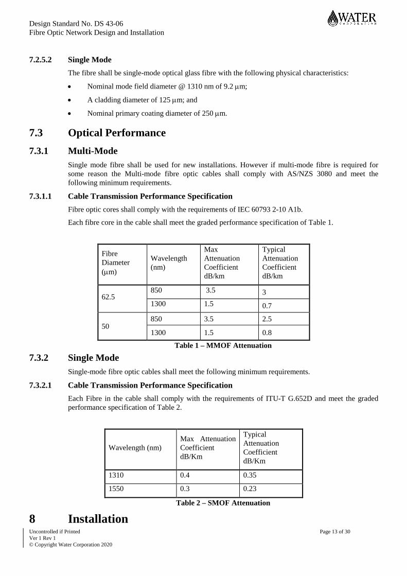
7.3 Optical Performance 7.3.1 Multi-Mode
Single mode fibre shall be used for new installations. However if multi-mode fibre is required for some reason the Multi-mode fibre optic cables shall comply with AS/NZS 3080 and meet the following minimum requirements.
7.3.1.1 Cable Transmission Performance Specification Fibre optic cores shall comply with the requirements of IEC 60793 2-10 A1b.
Each fibre core in the cable shall meet the graded performance specification of Table 1.
Fibre Diameter (µm)
Wavelength (nm)
Max Attenuation Coefficient dB/km
Typical Attenuation Coefficient dB/km
62.5 850 3.5 3 1300 1.5 0.7
50 850 3.5 2.5
1300 1.5 0.8
Table 1 – MMOF Attenuation
7.3.2 Single Mode Single-mode fibre optic cables shall meet the following minimum requirements.
7.3.2.1 Cable Transmission Performance Specification Each Fibre in the cable shall comply with the requirements of ITU-T G.652D and meet the graded performance specification of Table 2.
Wavelength (nm) Max Attenuation Coefficient dB/Km
Typical Attenuation Coefficient dB/Km
1310 0.4 0.35
1550 0.3 0.23
Table 2 – SMOF Attenuation
8 Installation

Design Standard No. DS 43-06 Fibre Optic Network Design and Installation
Uncontrolled if Printed Page 14 of 30 Ver 1 Rev 1 © Copyright Water Corporation 2020
8.1 Depth The minimum standard depth of cover that shall apply to underground fibre installations shall be in accordance with the “Utility Providers Code of Practice for Western Australia” section 8.1.3 for telecommunication installations. The standard depths of cover that are to be applied are:
• 450mm for excavation installations; and
• 600mm for trenchless installations.
8.2 Trenching All excavations shall comply with DS62-01 section 7.4.
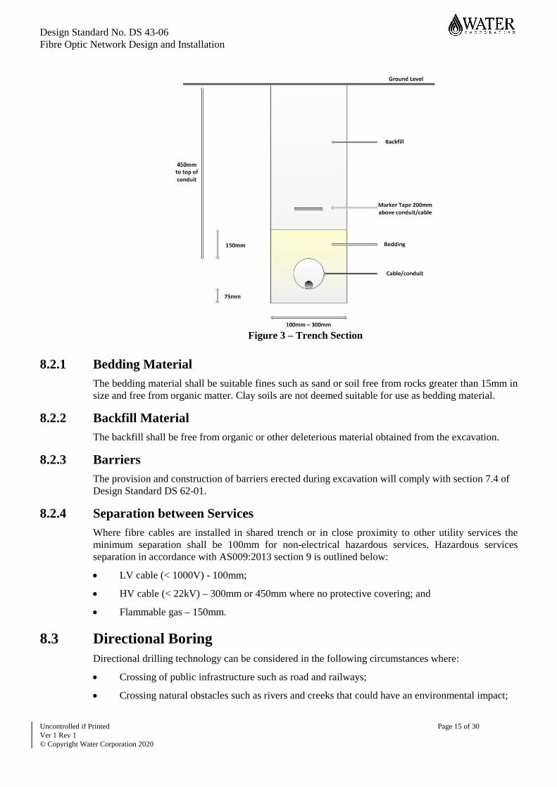
The depth of trench will be of sufficient depth to ensure that the cable /conduit will be bedded in 100mm of bedding material as per figure 3.
The width of trenches will be as small as possible (typically 100 to 300mm is common). However consideration must be given to the size of conduit/cable used and the ability of the soil to maintain stable trench walls to avoid collapse.
After bedding and surrounding the cable/conduit the remainder of the trench shall be backfilled with excavated material (if suitable).
The backfill material shall be placed and compacted in layers between 150mm-300m loose depths to not less than 95% of the maximum dry density ratio in accordance with Section 5 of AS 1289.
Backfilling shall be undertaken such that the finished surface level does not settle below the original surface level.
Detectable white marker tape incorporating stainless steel tracer wire complying with AS 2648 and 4275 shall be laid continuously along the route of the cable approximately 200mm above the cable/conduit.
Topsoil and grass is to be preserved for reinstatement where possible.
Fibre cable installed directly into an open trench shall be installed with zero tension and in a manner that does not compromise the cables performance by twisting and/or excessive bending.
Design Standard No. DS 43-06 Fibre Optic Network Design and Installation
Uncontrolled if Printed Page 15 of 30 Ver 1 Rev 1 © Copyright Water Corporation 2020
Figure 3 – Trench Section
8.2.1 Bedding Material The bedding material shall be suitable fines such as sand or soil free from rocks greater than 15mm in size and free from organic matter. Clay soils are not deemed suitable for use as bedding material.
8.2.2 Backfill Material The backfill shall be free from organic or other deleterious material obtained from the excavation.
8.2.3 Barriers The provision and construction of barriers erected during excavation will comply with section 7.4 of Design Standard DS 62-01.
8.2.4 Separation between Services Where fibre cables are installed in shared trench or in close proximity to other utility services the minimum separation shall be 100mm for non-electrical hazardous services. Hazardous services separation in accordance with AS009:2013 section 9 is outlined below:
• LV cable (< 1000V) - 100mm;
• HV cable (< 22kV) – 300mm or 450mm where no protective covering; and
• Flammable gas – 150mm.
8.3 Directional Boring Directional drilling technology can be considered in the following circumstances where:
• Crossing of public infrastructure such as road and railways;
• Crossing natural obstacles such as rivers and creeks that could have an environmental impact;

Design Standard No. DS 43-06 Fibre Optic Network Design and Installation
Uncontrolled if Printed Page 16 of 30 Ver 1 Rev 1 © Copyright Water Corporation 2020
• In areas where the density of underground services prohibits the use of standard trenching techniques; and
• Costly reinstatement works in restoring existing paved or bitumen areas.
All bores shall be installed by competent staff trained in applicable bore practise including location of services and compliance with all legislative statuary, local authority and other authorities’ regulations and restrictions.
8.4 Direct Buried The cable directly installed into an open trench will required the same bedding, compaction and reinstatement requirements as outlined in 8.2.
Where the cable is installed using trenchless methods as direct ripping or vibratory ploughing, these methodologies require considerably less site preparation and reinstatement. Cable bedding is not required as the fine sand particles are washed down around the cable to provide a soft bed. With little or no excavation there is no requirement for backfilling or compaction apart from levelling the surface.
8.5 Conduit Conduit shall be installed in trenches and used to transport the fibre cable in circumstances where multiple cables may be required or in built up areas to increase cable protection.
The conduit shall be installed where practical in direct straight lines and maintaining the standard depth between pits.
All joins between conduit lengths and or fitting shall be glued in accordance with AS2032:2006 and the manufacturer’s specifications.
All conduits shall be sealed at the pit and building entries to prevent rodent occupation.
All newly installed conduits shall have hauling rope installed to assist in fibre installation.
8.5.1 Size The conduit size used will depend on the number of cables and cable dimensions to be transported. For new installations of conduit, the conduit size installed should have a 50% space availability post fibre cable installation for future use.
The minimum conduit size to be used is 32mm. Where there is the potential for a future increase of fibre capacity through the conduit route, then an increase in conduit size shall be considered to 50mm or 100mm.
8.5.2 General Pipe Specifications UPVC (Poly Vinyl Chloride) pipes shall have the following general specifications in accordance with AS2053:
• Ultraviolet protection;
• Supplied in suitable lengths, nominally 4.5m;
• Pipe shall be white in colour; and
• PE (Polyethylene) conduit shall be used where directional boring techniques have been used.
Design Standard No. DS 43-06 Fibre Optic Network Design and Installation
Uncontrolled if Printed Page 17 of 30 Ver 1 Rev 1 © Copyright Water Corporation 2020
8.5.3 Fittings All UPVC pipe fittings for shall have the following general specifications in accordance with AS2053:
• Ultraviolet protection;
• Pipe bends shall be of minimum 500mm radius and shall not be less than the minimum bending radius of the cable;
• Couplings shall be used at pipe joins where a socket is not available;
• Pipe bushes shall be fitted to pipe ends in pits & manholes to alleviate sharp edges to avoid cable damage during hauling;
• Empty pipes or pipes that are yet to be terminated shall be sealed with a suitable pipe plug or end cap; and
• Fittings will be white in colour.
8.6 Pits Pits are utilised to house the fibre optic cable loops and fibre optic infrastructure. Pits provide a means to gain access to installed infrastructure for the purpose of maintenance, fault-finding, hauling, change of direction and provision of new services.
Pits are dimensioned to permit the accommodation of required fibre optic infrastructure and cables based upon the functionality of the pit. The pits shall be dimensioned to ensure that the fibre optic cables can be managed without exceeding the minimum bending radius and jointing enclosure are able to be mounted vertically. In addition to these basic requirements, it is necessary to consider the depth of cover for the associated conduits.
Pits shall be installed at:
• Building entries;
• Cable joint and loop locations;
• Each change of direction in conduit;
• At intervals of no greater than 100 meters in a straight conduit section; and
• Low point of cable route to aid drainage, preference is for this to coincide with another of the pit functionalities as described above i.e. low point of cable route and change of direction.
Pits shall be located wherever possible outside of trafficable areas.
The pits shall be standard telecommunication pit sizes labelled with “Communications” or “Comms” as per AS S008:2010 section 5.8.
8.6.1 Pit Materials Pits may be made from precast concrete, glass reinforced plastic (GRP), glass reinforced cement (GRC), High Density Polyethylene (HDPE) or other materials approved by the Water Corporation.
• The pit lid shall weigh no more than 38kg;
• The pit lid shall have a lifting hole at each end capable of being used with an industry accepted lifting tool;
• The type of construction will depend on the size, location and the loading to which the pit will be subjected to;
Design Standard No. DS 43-06 Fibre Optic Network Design and Installation
Uncontrolled if Printed Page 18 of 30 Ver 1 Rev 1 © Copyright Water Corporation 2020
• Pits installed in roadways or parking areas that will be subject to vehicular traffic will require a concrete pit with a trafficable Gatic or similar steel plate cover; and
• Drainage holes shall be provided in the pit base to allow drainage of water.
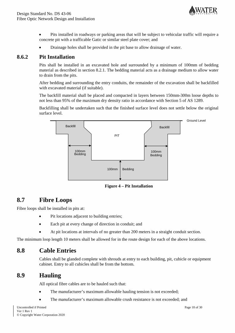
8.6.2 Pit Installation Pits shall be installed in an excavated hole and surrounded by a minimum of 100mm of bedding material as described in section 8.2.1. The bedding material acts as a drainage medium to allow water to drain from the pits.
After bedding and surrounding the entry conduits, the remainder of the excavation shall be backfilled with excavated material (if suitable).
The backfill material shall be placed and compacted in layers between 150mm-300m loose depths to not less than 95% of the maximum dry density ratio in accordance with Section 5 of AS 1289.
Backfilling shall be undertaken such that the finished surface level does not settle below the original surface level.
Ground Level
BackfillBackfill
100mm 100mm
100mm
PIT
Bedding
Bedding Bedding
Figure 4 – Pit Installation
8.7 Fibre Loops Fibre loops shall be installed in pits at:
• Pit locations adjacent to building entries;
• Each pit at every change of direction in conduit; and
• At pit locations at intervals of no greater than 200 meters in a straight conduit section.
The minimum loop length 10 meters shall be allowed for in the route design for each of the above locations.
8.8 Cable Entries Cables shall be glanded complete with shrouds at entry to each building, pit, cubicle or equipment cabinet. Entry to all cubicles shall be from the bottom.
8.9 Hauling All optical fibre cables are to be hauled such that:
• The manufacturer’s maximum allowable hauling tension is not exceeded;
• The manufacturer’s maximum allowable crush resistance is not exceeded; and
Design Standard No. DS 43-06 Fibre Optic Network Design and Installation
Uncontrolled if Printed Page 19 of 30 Ver 1 Rev 1 © Copyright Water Corporation 2020
• The allowable minimum bending radius of the cable is not exceeded under tension or at rest as specified by the manufacturer.
Twisting of the cable shall be avoided as it places stress on the cable. To avoid twisting the cable:
• The cable shall be rolled off drums using a spool and not spun off the drum ends;
• A “figure 8” is used to lay up the cable; and
• A swivel pulling eye shall be used to accommodate the twisting forces on the cable caused by the pulling tension.
8.9.1 Cable Hauling Equipment All hauling winches used to haul cable into pipes shall be fitted with continuous tension monitoring facilities, early warning indicators and automatic cut-out devices that will activate prior to excessive tension being placed on the cable at greater than 90% of manufacturer’s specified maximum.
8.9.2 Ropes for Hauling The hauling rope with minimal longitudinal stretch must be used to prevent surging during hauling which may cause the maximum hauling tension to be exceeded. Kevlar or similar polyester braided rope and with an outside diameter of not less than 8mm is recommended.
Hauling rope to have minimum tensile strength of 5Kn and minimum 10 year design life.
Polypropylene rope SHALL NOT be used for mechanically hauling optical fibre cable. It may be used for manual hauling, e.g. over short sections, for lead-ins, and cabling within buildings. This is typically for sections of approximately up to 100 metres or sections which can be easily pulled by one person.
8.9.3 Cable Guides Suitable cable guides shall be fitted at all pipe entry and exit points along the route to prevent cable damage and to reduce friction/hauling tension during the haul. Water based cable lubricant shall be used if necessary to reduce friction.
8.10 Tray/Risers Cable Tray shall be as specified in ”Water Corporation – Installation of a Structured Cabling System Specification” section 3.3.4.4.
Cable trays or “ladder racks” shall be used to transport fibre installed in ceilings and in riser shafts.
Cables in vertical runs should be supported and secured at regular small intervals, in a reasonable number of locations. Optical fibre cables intended for vertical applications have a calculated maximum vertical rise value.
Cables should be supported by cable ties, straps or clamps in wiring closets to avoid damage.
8.10.1 FiberGuide A FiberGuide system shall be installed in communication room overhead tray work to transport patch leads between the main fibre distributions to the equipment racks. The FiberGuide system shall have adequate bending and waterfalls to equipment racks for the smooth transition of patch leads.
8.11 Route Marking After installation of the fibre route, the external installation must be clearly marked with cable markers at change of directions, pit locations or at intervals not exceeding 250m.

Design Standard No. DS 43-06 Fibre Optic Network Design and Installation
Uncontrolled if Printed Page 20 of 30 Ver 1 Rev 1 © Copyright Water Corporation 2020
Buried Cable route shall be surveyed to a horizontal accuracy of 0.1 m and recorded as outlined in section 14.1.
9 Cable Jointing Intermediate cable joints may be required where there are:
• Separate fibre cable sections where cables cannot be installed as a continuous cable run;
• Cable repairs; and
• Spurs off the main distribution cable.
The joints can be wall mounted for internal cabling or housed within pits for external installations.
External cable joints located in pits shall be mounted vertically where possible to prevent water ingress. The external joint enclosures shall be IP68 rated.
10 Cable Termination All fibre cores within a cable shall be terminated and presented on a FOBOT.
10.1 FOBOT The FOBOT shall be mounted in a 19-inch rack or DIN mounted and has the following functionality:
• Facility for the management, storage, organisation and re-arrangement of optical fibres, pigtails, optical components and other network components;
• Available accessories for the termination of most common cable types and constructions. All fibre cable elements shall be routed in such a way that no transmission degradation is seen when accessing these cable elements. The minimum bend radius of the fibres shall not be exceeded throughout the whole organiser system;
• The unit shall allow easy access during installation, maintenance and addition of all types of organiser modules;
• The FOBOT shall be of a suitable size as to accommodate the cables used and have sufficient ports to terminate all cable fibre cores on the FOBOT; and
• The FOBOT termination units shall be approved for use by Water Corporation.
Different fibre types shall be terminated on separate FOBOTS where practical. Additional cables provisioned at a facility shall be installed onto a new FOBOT. Where insufficient space is available to install a new FOBOT, the cable can be terminated and presented onto an existing FOBOT with sufficient capacity, the Water Corporation Design Manager approval is required.
Unused ports in the FOBOT shall be covered by suitable plugs or protective covers.
10.2 Connectors and Pigtails All fibres terminated in the FOBOT shall be presented on a connector and shall be forward facing for ease in patching.
All pigtail/patch lead connectors will be factory fitted and tested.
Patch lead and pigtail connectors including adapters shall be colour coded as follows:
Fibre / Connector Type Connector Through Adapter
Design Standard No. DS 43-06 Fibre Optic Network Design and Installation
Uncontrolled if Printed Page 21 of 30 Ver 1 Rev 1 © Copyright Water Corporation 2020
SMOF / UPC Blue Blue
SMOF / APC Green Green
MMOF 62.5/125 OM1 / PC Beige Beige
MMOF 50/125 OM3 / PC Aqua Aqua
Table 3 – Connector Standard Colours
Where practical UPC (Ultra Physical Contact) connectors should be used as standard, however if high bandwidth transmission is used then APC (Angled Physical Contact) connectors should be considered.
10.2.1 Connector Types All new FOBOTS shall be fitted with LC connectors.
The following are the main connector types in use in the Water Corporation network.
10.2.1.1 SC Connector The SC is a snap connector with 2.5mm ferrule.
Figure 5 – SC Connector
10.2.1.2 FC Connector The FC is threaded coupling connector with 2.5mm ferrule.
Figure 6 – FC Connector
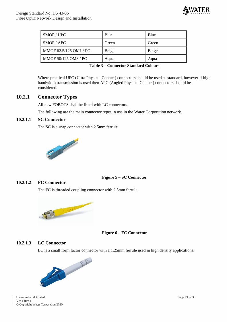
10.2.1.3 LC Connector
LC is a small form factor connector with a 1.25mm ferrule used in high density applications.

Design Standard No. DS 43-06 Fibre Optic Network Design and Installation
Uncontrolled if Printed Page 22 of 30 Ver 1 Rev 1 © Copyright Water Corporation 2020
Figure 7- LC Connector
10.2.2 Inspection and Cleaning All connectors shall be cleaned and inspected prior to termination.
Connectors shall always be handled carefully. The ferrule body and ferrule/fibre end-face shall not be touched as this can cause contamination by dirt and/or skin residues and oils.
When in storage or not attached to equipment a connector ferrule must have a dust cap attached.
All leads/pigtails shall meet the pass criteria outlined in Figure 7.
Figure 8 – Connector Inspection
10.3 Patch Leads Patch Leads are to be of suitable length to reach the patch panel from the designated transmission equipment location.
The patch leads core diameter shall match the core diameter of the terminated cable.
10.3.1 Patch Lead Management Adequate space must be allowed for in racks and termination locations for patch lead management. Consideration shall be given for the following:
Storage trays are used to store excess patch lead length. The size shall be determined by the number patch leads terminating in the rack and the excess length required for storage.
Use of horizontal and vertical cable managers allow the neat routing of patch leads from equipment in the rack and protect leads from damage.
11 Testing and Commissioning Optical fibre cable acceptance testing is intended to:
• Determine the acceptability of the installed cables and terminations;
• Confirm the compatibility of both cable designs and installation techniques;
• Establish reference records for maintenance and long-term monitoring of fibre performance; and

Design Standard No. DS 43-06 Fibre Optic Network Design and Installation
Uncontrolled if Printed Page 23 of 30 Ver 1 Rev 1 © Copyright Water Corporation 2020
• Provide information for transmission system design.
The acceptance testing criteria requirements outlined in this document are mandatory and apply to new installed optical cables and existing network repairs. Any re-measurements carried out on this optical fibre cable should be tested within the guidelines of this document.
Appendix A and Appendix B provide typical test record sheets that shall be utilised by the tester to record the results of fibre optic testing.
11.1 Competency All fibre testing must be performed by competent personnel that is registered with an Australian Communications and Media Authority (ACMA) Accredited Registrar under the Cabling Provider Rules (CPR) and must be experienced in the use of OTDR, light source and optical power meters.
11.2 Test Equipment All test equipment must be calibrated prior to testing. Evidence in the form of a valid calibration certificate must be provided at the time of testing.
11.2.1 Power Meter Power Meter equipment shall comply with Bellcore Technical Reference TR-TSY-000886 ‘Generic Criteria for Fibre Power Meters’
11.2.2 Stabilised Light Source Stabilised Light Source equipment shall comply with Bellcore Technical Reference TR-TSY-000887 ‘Generic Criteria for Optical Stabilised Light Sources’
11.2.3 Optical Time Domain Reflectometer (OTDR) OTDR instruments shall comply with Telcordia/Bellcore Standard GR-196-CORE ‘Generic Requirements for Optical Time Domain Reflectometer (OTDR) - Type Equipment’ and must be immune to polarisation noise.
11.3 Cable Acceptance Measurements Splicing, terminations and testing of the fibre optic cable shall be to the satisfaction of the responsible Water Corporation Representative.
After the fibre cables are installed, all fibres shall be tested. Satisfactory completion and recording of the testing is required for cable acceptance.
For fully terminated fibre sections under 250m at a minimum, the Insertion loss shall be measured across all fibres. Fibre sections over 250m shall have both Insertion loss and link loss measured on all fibres.
Should the Insertion Loss exceed the maximum limit outlined in 11.3.1 then further testing using the OTDR shall be employed to locate the fault. The resulting OTDR traces should be analysed with consideration to the splice, section and connection loss. For sections less than 250m, long launch leads shall be used in OTDR testing
Any faults highlighted via the cable acceptance measurements shall be remedied.

Design Standard No. DS 43-06 Fibre Optic Network Design and Installation
Uncontrolled if Printed Page 24 of 30 Ver 1 Rev 1 © Copyright Water Corporation 2020
11.3.1 Insertion Loss The Insertion loss test is carried out on terminated fibres to determine the overall end-to-end power level over the fibre link section. Using a Stabilised light source and power meter the Insertion Loss (IL) of each fibre shall be measured in both directions.
These results should be compared with predictions based on the manufacturer’s SMOF geometrical properties and minimum splice loss criteria.
The maximum two-way (average) Insertion Loss shall not exceed the following criteria:
For Single Mode Fibre (SMOF)
• Maximum Loss at 1310nm (IL) = 0.35L + 0.1N + 0.75C
• Maximum Loss at 1550nm (IL) = 0.23L + 0.1N + 0.75C
For Multi-Mode Fibre (MMOF) for 62.5 µm
• Maximum Loss at 850nm (IL) = 3L + 0.1N + 0.75C
• Maximum Loss at 1300nm (IL) = 0.70L + 0.1N + 0.75C
For Multi-Mode Fibre (MMOF) for 50 µm
• Maximum Loss at 850nm (IL) = 2.5L + 0.1N + 0.75C
• Maximum Loss at 1300nm (IL) = 0.80L + 0.1N + 0.75C
Where
IL = Maximum allowable Insertion Loss in dB
L = Optical section link Length in km
N = Number of splices including pigtail terminations
C = Total number of through Connectors.
All Insertion Loss measurements at both wavelengths shall be recorded. If a fibre exceeds the above criteria then the insertion loss value shall be appropriately marked and recorded as an exception.
11.3.2 Link Loss The Link Loss (LL) measurement shall be performed on fibres (terminated or unterminated) to confirm the integrity of the cable link without including the performance of the end connectors or pigtails.
The LL shall be tested and recorded in both directions utilising the OTDR (Two-point method i.e. position the first cursor just beyond the front-end attenuation saturation dead zone where the trace is linear and position the second cursor at the end of the trace just before the trace begins to rise).
The two-way (average) OTDR LL shall not exceed the following:
For Single Mode Fibre (SMOF)
• Maximum Loss at 1310nm (IL) = 0.35L + 0.1N
• Maximum Loss at 1550nm (IL) = 0.23L + 0.1N
For Multi-Mode Fibre (MMOF) for 62.5 µm
• Maximum Loss at 850nm (IL) = 3L + 0.1N
• Maximum Loss at 1300nm (IL) = 0.70L + 0.1N
For Multi-Mode Fibre (MMOF) for 50 µm

Design Standard No. DS 43-06 Fibre Optic Network Design and Installation
Uncontrolled if Printed Page 25 of 30 Ver 1 Rev 1 © Copyright Water Corporation 2020
• Maximum Loss at 850nm (IL) = 2.5L + 0.1N
• Maximum Loss at 1300nm (IL) = 0.80L + 0.1N
Where
LL = Maximum allowable Link Loss in dB
L = Optical link length in km
N = Number of splices excluding pigtail terminations.
If a fibre fails the Link Loss after a number of re-measurements, then a more comprehensive evaluation of the fibre link should be undertaken to determine the high loss i.e. re-check of any irregularities, splice losses and fibre attenuation co-efficient (dB/km).
11.3.3 Connector/Pigtail Loss Connector and pigtail measurements are taken to determine the overall performance of the individual connector/pigtail combination at either end of the fibre link.
For each fibre the difference between the average of Insertion Loss (IL) minus the OTDR average Link Loss (LL), shall not exceed 1.5dB.
If the results exceed 1.5dB, a more comprehensive evaluation of each connector/pigtail at both ends shall be undertaken to determine the high loss (i.e. investigate the launch conditions of each connector/pigtail using OTDR in high resolution mode, check and clean connectors etc.).
11.3.4 Splice Loss The optical distance and magnitude of all splices (joints) shall be measured from both directions using an OTDR. The loss of any splice shall not exceed 0.1dB (average) at either wavelength.
Any splice loss that exceeds the above criteria shall be re-spliced. If the splice does not improve after two attempts at resplicing then the splice shall be accepted but reported and recorded as a high splice loss.
11.3.5 Section Loss Fibre attenuation co-efficient (dB/km) between any known events shall not exceed the maximum allowable attenuation as outlined in table 4. In tables 1 and 2, the expected typical sectional losses are shown.
Fibre Type Fibre Diameter (µm)
Wavelength (nm)
Attenuation Coefficient dB/Km
MMOF 62.5 850 3.5
1300 1.5
MMOF 50 850 3.5
1300 1.5
SMOF 9.2 1310 0.4

Design Standard No. DS 43-06 Fibre Optic Network Design and Installation
Uncontrolled if Printed Page 26 of 30 Ver 1 Rev 1 © Copyright Water Corporation 2020
1550 0.3
Table 4 – Section Loss Attenuation
If the sectional loss exceeds the above criteria the cable section shall be deemed faulty and will require removal of the affected sections.
12 Safety There are inherent risks associated with the use and installation of fibre optic systems.
12.1 Laser Safety Laser safety procedures and control measures apply to laser light that is transmitted in optical fibres. The following are recommended when working with any optical fibre system.
• Do not look at live fibre ends or connector faces with the unprotected eye;
• Use indirect viewing aids were possible (e.g. camera scopes for connector inspection);
• Only use a microscope to view live fibre output/transmission when the light source used is a Class 1 source. Do not use a microscope to view live fibre output when any other source is used;
• Any unterminated single or multiple fibre ends should be individually or collectively covered when not being worked on. They should not be visible and sharp ends should not be exposed. Suitable covering methods include the use of a splice protector or tape. End caps should always be attached to unmated connectors;
• When testing the optical fibre system, optical power source should be the last to be connected (before turning the source on), and the first to be disconnected (after turning the source off); and
• Working on live fibres transmitting laser light of Class 3B or Class 4 is not recommended.
12.2 Fibre Handling Safety gloves and eye protection shall be used when handling or terminating fibre.
Fibre particles created during termination and splicing can be dangerous. The particles are extremely sharp and can easily penetrate the skin. All fibre particles shall be properly deposed of in sharps bins.
13 Labelling Labelling is to meet the relevant Water Corp standards in place at the time of construction and as a minimum meet the following requirements.
All cables and end points shall be clearly labelled. Termination points shall be labelled on FOBOTs. Backbone cables shall be labelled within FOBOTs. Patch cables shall be labelled.
Cable numbers shall be positioned in the most accessible position adjacent to the point of termination to facilitate cable identification.
In addition to any information labels, AS/ACIF S009:2006 (Section 11.1) requires fibre optic cables to be labelled in order to:
• Distinguish them from other cable types;
• Warn of potential laser radiation in excess of the accessible emission limit (AEL); and
• Retain any manufacturer warning or instruction labels.

Design Standard No. DS 43-06 Fibre Optic Network Design and Installation
Uncontrolled if Printed Page 27 of 30 Ver 1 Rev 1 © Copyright Water Corporation 2020
14 Records As-built information shall be supplied post any fibre network installation, this shall include the following:
• Vertical alignment;
• Depth;
• Installation methodology i.e. conduit, direct bury, etc.
• Conduit size, number and spacing if applicable;
• Pit size and location; and
• Details of all materials used in solution.
14.1 Drawings The requirements of DS62-01 section 7.2.1 shall be met. The following drawings shall be created or updated to show any changes to the fibre network:
• The site electrical layout drawing shall be modified to show the physical location of the fibre route, its installation type such as direct or in conduit and its proximity to existing services;
• System drawings that show the usage and connections to the fibre, typically this is shown on the SCADA Block Diagrams; and
• Patching drawings that show the patching of equipment to the FOBOT including patch lead labelling and FOBOT and equipment port usage shall be produced.
14.2 Cable Acceptance Results All cable acceptance results shall be submitted to the Project Manager including all OTDR raw and or modified trace files.
The insertion losses and link losses for each wavelength tested shall be tabulated on an excel file.
14.3 Vendor Supplied Information All vendor supplied information shall be submitted to the Project Manager including:
• Material Safety Data Sheets (MSDS);
• Manuals and/or data sheets;
• Warranties; and
• Compliance certificates.

Design Standard No. DS 43-06 Fibre Optic Network Design and Installation
Uncontrolled if Printed Page 28 of 30 Ver 1 Rev 1 © Copyright Water Corporation 2020
15 Appendix A
JOB TITLE : DATE :
CABLE DESIGNATION/S : FILE :
OPTICAL FIBRE SECTION :
OPTICAL LINK LENGTH (OTDR)(L): km LIGHT SOURCE END A :
LIGHT SOURCE END B :
END A : OPERATOR END A : LIGHT METER END A :
END B : OPERATOR END B : LIGHT METER END B :
IL 1310nmA end B end Length (Km) Connectors Splices Calc IL A-B B-A Avg A-B B-A LL IL-LL dB/Km
1 12 23 34 45 56 67 78 89 910 1011 1112 1213 1314 1415 1516 1617 1718 1819 1920 2021 2122 2223 2324 24
1310nm OTDR LossFibre No. Calc IL @ 1310
Figure 9 – 1310nm Test Record Sheet

16 Appendix B
JOB TITLE : DATE :
CABLE DESIGNATION/S : FILE :
OPTICAL FIBRE SECTION :
OPTICAL LINK LENGTH (OTDR)(L): km LIGHT SOURCE END A :
LIGHT SOURCE END B :
END A : OPERATOR END A : LIGHT METER END A :
END B : OPERATOR END B : LIGHT METER END B :
IL 1550nmA end B end Length (Km) Connectors Splices Calc IL A-B B-A Avg A-B B-A LL IL-LL dB/Km
1 12 23 34 45 56 67 78 89 910 1011 1112 1213 1314 1415 1516 1617 1718 1819 1920 2021 2122 2223 2324 24
Fibre No. Calc IL @ 1550 1550nm OTDR Loss
Figure 10 – 1550nm Test Record Sheet

END OF DOCUMENT