Fibre OptiC Distributed Strain and Temperature · PDF fileFiber Optic Distributed Strain and...
11
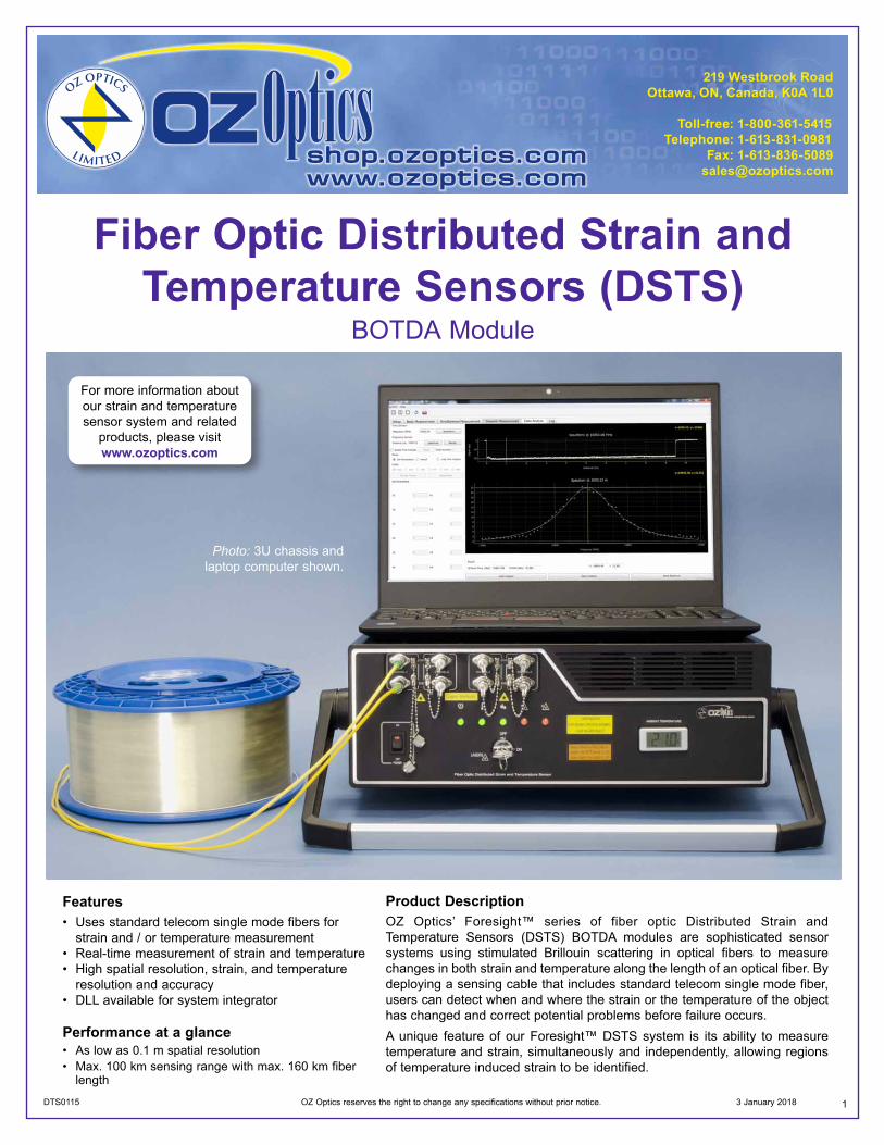
1 DTS0115 OZ Optics reserves the right to change any specifications without prior notice. 3 January 2018 Fiber Optic Distributed Strain and Temperature Sensors (DSTS) BOTDA Module Features • Uses standard telecom single mode fibers for strain and / or temperature measurement • Real-time measurement of strain and temperature • High spatial resolution, strain, and temperature resolution and accuracy • DLL available for system integrator Performance at a glance • As low as 0.1 m spatial resolution • Max. 100 km sensing range with max. 160 km fiber length Product Description OZ Optics’ Foresight™ series of fiber optic Distributed Strain and Temperature Sensors (DSTS) BOTDA modules are sophisticated sensor systems using stimulated Brillouin scattering in optical fibers to measure changes in both strain and temperature along the length of an optical fiber. By deploying a sensing cable that includes standard telecom single mode fiber, users can detect when and where the strain or the temperature of the object has changed and correct potential problems before failure occurs. A unique feature of our Foresight™ DSTS system is its ability to measure temperature and strain, simultaneously and independently, allowing regions of temperature induced strain to be identified. For more information about our strain and temperature sensor system and related products, please visit www.ozoptics.com Photo: 3U chassis and laptop computer shown.
Transcript of Fibre OptiC Distributed Strain and Temperature · PDF fileFiber Optic Distributed Strain and...
1DTS0115 OZ Optics reserves the right to change any specifications without prior notice. 3 January 2018
Fiber Optic Distributed Strain andTemperature Sensors (DSTS)
BOTDA Module
Features• Uses standard telecom single mode fibers for
strain and / or temperature measurement• Real-time measurement of strain and temperature• High spatial resolution, strain, and temperature
resolution and accuracy• DLL available for system integrator
Performance at a glance• As low as 0.1 m spatial resolution• Max. 100 km sensing range with max. 160 km fiber
length
Product DescriptionOZ Optics’ Foresight™ series of fiber optic Distributed Strain andTemperature Sensors (DSTS) BOTDA modules are sophisticated sensorsystems using stimulated Brillouin scattering in optical fibers to measurechanges in both strain and temperature along the length of an optical fiber. Bydeploying a sensing cable that includes standard telecom single mode fiber,users can detect when and where the strain or the temperature of the objecthas changed and correct potential problems before failure occurs.A unique feature of our Foresight™ DSTS system is its ability to measuretemperature and strain, simultaneously and independently, allowing regionsof temperature induced strain to be identified.
For more information aboutour strain and temperaturesensor system and related
products, please visitwww.ozoptics.com
Photo: 3U chassis andlaptop computer shown.

2
Oil and Gas Pipeline Monitoring• Pipeline leakage monitoring• Up to 100 km sensing range per channel• High spatial resolution supports localized measurement
with long sensing range• Short acquisition / response time
Structural Health Monitoring (SHM)• Sediment monitoring• Strain and crack monitoring• Up to 100 km sensing range per channel• High spatial resolution supports localized measurement
with long range object
Oil and Gas applications
Civil Engineering applications
Oil and Gas Well Monitoring• Well integrity management• Temperature, strain and pressure monitoring with proper
sensing cable and installation• Not sensitive to hydrogen which may change the
attenuation of the fi ber
Refinery Efficiency Sensing• Improve the effi ciency of the refi nery per distributed
temperature profi le• Reduce downtime while ensuring safety levels• Uses low cost telecom single mode fi ber cable
Dam Monitoring• Dam internal temperature monitoring• Crack / sediment / deformation / seepage monitoring• Up to 100 km sensing range per channel
3
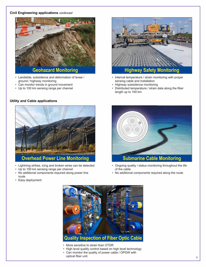
Civil Engineering applications continued
Geohazard Monitoring• Landslide, subsidence and deformation of levee /
ground / highway monitoring• Can monitor trends in ground movement• Up to 100 km sensing range per channel
Highway Safety Monitoring• Internal temperature / strain monitoring with proper
sensing cable and installation• Highway subsidence monitoring• Distributed temperature / strain data along the fi ber
length up to 100 km
Overhead Power Line Monitoring• Lightning strikes, icing and broken wires can be detected• Up to 100 km sensing range per channel• No additional components required along power line
route• Easy deployment
Submarine Cable Monitoring• Ongoing quality / status monitoring throughout the life
of the cable• No additional components required along the route
Utility and Cable applications
Quality Inspection of Fiber Optic Cable• More sensitive to strain than OTDR• High level quality control based on high level technology• Can monitor the quality of power cable / OPGW with
optical fi ber unit
4
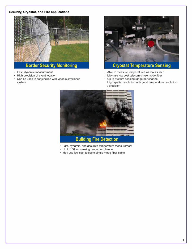
Security, Cryostat, and Fire applications
Border Security Monitoring• Fast, dynamic measurement• High precision of event location• Can be used in conjunction with video surveillance
system
Cryostat Temperature Sensing• Able to measure temperatures as low as 25 K• May use low cost telecom single mode fi ber• Up to 100 km sensing range per channel• High spatial resolution with good temperature resolution
/ precision
Building Fire Detection• Fast, dynamic, and accurate temperature measurement• Up to 100 km sensing range per channel• May use low cost telecom single mode fi ber cable
5
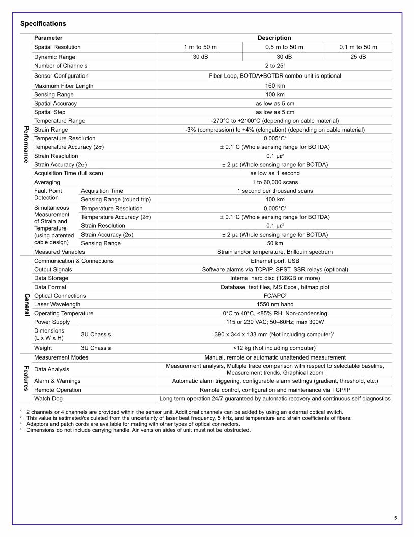
Specifications
1 2 channels or 4 channels are provided within the sensor unit. Additional channels can be added by using an external optical switch.2 This value is estimated/calculated from the uncertainty of laser beat frequency, 5 kHz, and temperature and strain coefficients of fibers.3 Adaptors and patch cords are available for mating with other types of optical connectors.4 Dimensions do not include carrying handle. Air vents on sides of unit must not be obstructed.
Performance
Parameter DescriptionSpatial Resolution 1 m to 50 m 0.5 m to 50 m 0.1 m to 50 mDynamic Range 30 dB 30 dB 25 dBNumber of Channels 2 to 251
Sensor Configuration Fiber Loop, BOTDA+BOTDR combo unit is optional
Maximum Fiber Length 160 kmSensing Range 100 kmSpatial Accuracy as low as 5 cmSpatial Step as low as 5 cmTemperature Range -270°C to +2100°C (depending on cable material)Strain Range -3% (compression) to +4% (elongation) (depending on cable material)Temperature Resolution 0.005°C2
Temperature Accuracy (2σ) ± 0.1°C (Whole sensing range for BOTDA)Strain Resolution 0.1 µε2
Strain Accuracy (2σ) ± 2 µε (Whole sensing range for BOTDA)Acquisition Time (full scan) as low as 1 secondAveraging 1 to 60,000 scansFault PointDetection
Acquisition Time 1 second per thousand scansSensing Range (round trip) 100 km
SimultaneousMeasurement of Strain andTemperature (using patentedcable design)
Temperature Resolution 0.005°C2
Temperature Accuracy (2σ) ± 0.1°C (Whole sensing range for BOTDA)Strain Resolution 0.1 µε2
Strain Accuracy (2σ) ± 2 µε (Whole sensing range for BOTDA)Sensing Range 50 km
Measured Variables Strain and/or temperature, Brillouin spectrum
General
Communication & Connections Ethernet port, USBOutput Signals Software alarms via TCP/IP, SPST, SSR relays (optional)Data Storage Internal hard disc (128GB or more)Data Format Database, text files, MS Excel, bitmap plotOptical Connections FC/APC3
Laser Wavelength 1550 nm bandOperating Temperature 0°C to 40°C, <85% RH, Non-condensingPower Supply 115 or 230 VAC; 50–60Hz; max 300WDimensions(L x W x H) 3U Chassis 390 x 344 x 133 mm (Not including computer)4
Weight 3U Chassis <12 kg (Not including computer)
Features
Measurement Modes Manual, remote or automatic unattended measurement
Data Analysis Measurement analysis, Multiple trace comparison with respect to selectable baseline,Measurement trends, Graphical zoom
Alarm & Warnings Automatic alarm triggering, configurable alarm settings (gradient, threshold, etc.)Remote Operation Remote control, configuration and maintenance via TCP/IPWatch Dog Long term operation 24/7 guaranteed by automatic recovery and continuous self diagnostics

6
Related Products
Fiber Optic Sensor Probes, Components, Termination Kits, and Training
OZ Optics offers a full spectrum of fiber optic sensor probes, components, termination kits and training. OZ Optics' standard fiber optic productshave been used worldwide in high performance sensor and telecommunications applications since 1985. OZ Optics also offers specialty fiberoptic sensor probes and custom cabling for high temperature applications and other hostile and corrosive environments. System integrators withexperience in structural and pipeline monitoring will find that OZ Optics offers a complete suite of enabling products and services for installingand maintaining fiber optic systems. If you are planning a pipeline or structural monitoring project, please contact OZ Optics to learn more aboutour fiber optic solutions.
For more information about our strain and temperature sensor system and related products, please visit www.ozoptics.com.
Ordering Information
Part Number Description: DSTS-CT CO I-SR-MSR-AS-BOTDA-X-CH
For a field ready unit, replace the chassis type, computer type,and computer interface with a single letter “F.” Field ready unitsinclude a built-in computer, monitor, keyboard and mouse.
CT = Chassis Type of DSTS opto-electronics box3U = 3U chassis
CO = Computer TypeL = Laptop (requires 3U chassis)R1U = 1U computerX = Customer supplier computer
I = Internal Interface between DAQ andcomputerT = Thunderbolt (requires 3U chassis)S = Standard
SR = Spatial Resolution (m)1
0.1/100.1/500.5/100.5/501/101/50
Notes:1. Each DSTS can be configured for short haul operation, long haul operation or both. The configuration must be specified at the time of
purchase. The spatial resolution indicates the best resolution at the maximum sensing range. If the DSTS is configured for both short-hauland long-haul measurements then two numbers will be listed indicating the resolutions and maximum sensing range for each operatingmode. For example, suppose the DSTS unit needs to achieve 0.1 meter resolution over a 1 km range for short-haul applications, and 50 meter resolution over a 100 km range for long-haul applications. The part number will specify the spatial resolution (SR) as 0.1/50, andmaximum sensing range (MSR) as 1/100.
2. Maximum sensing range is 60 km or 100 km for long haul operation. Alternately, if the 0.1 m spatial resolution is chosen, a maximum sensingrange of 1 km is displayed for that resolution (for short haul operation). Maximum sensing range is described as 60, 1/60, 5/60, 100, 1/100,or 5/100.
3. The acquisition speed is described as normal or high speed. N and H are used respectively. The high-speed version is typically at least afactor of two faster than the normal-speed version during the acquisition of data.
3U model with laptop computerThe 3U version of the DSTS comes with removablecarrying handles. The user can easily replace thehandles with tabs (sold separately) that will allow theunit to be installed in a standard 19-inch rack.
Field-ready modelA field-ready model is optional for our customers.Please contact OZ Optics for detailed information.
CH = Number of channels2CH = 2 built-in channels4CH = 4 built-in channels
X = Connector Type3A = FC/APC
AS = Acquisition Speed3
N = NormalH = High Speed
MSR = Maximum Sensing Range (km)1,2
601/605/601001/1005/100

7
Optional Accessories
Bar Code Part Number Description
48298 DSTS-TRAVEL-CASE-1U/3UOptional aluminum carrying case for DSTS. Includes wheels and handle. Designed forchecking on airplane. Approximate dimensions: 23.75 (H) x 22.5 (W) x 15 (D). {60.3 cm x57.2 cm x 38.1 cm}.
48979 CI-1100-A2
Handheld Video Microscope kit for Fiber Optic Connector Inspection. The kit includes a 3.5” TFT LCD display with video probe. An ac power adapter with battery charger and arechargeable battery pack. It also includes one SC/FC PC female connector, one LC/PCfemale connector, one Universal 2.5 mm FC/PC male connector and one Universal 1.25 mmFC/PC male connector.
48980 CI-1100-A2-PT2-FS/APC/F Tip for SC and FC APC type female (in receptacle) connector for CI-1100-A2 handheldmicroscope.
36939 HUXCLEANER-2.5 Receptacle fiber cleaner for FC, SC and ST type.
5336 Fiber-Connector-Cleaner-SA Disposable Cletop reel type A optical fiber connector cleaner.
8122 SMJ-3A3A-1300/1550-9/125-3-1 1 meter long, 3 mm OD jacketed, 1300/1550 nm 9/125 µ Corning SMF 28e fiber patchcord,terminated with angled FC/APC connectors on both ends.
40536 SMJ-3AEA-1300/1550-9/125-3-11 meter long, 3 mm OD PVC cabled, 9/125 um 1300/1550 nm SM fiber patch cord,terminated with an angled FC/APC connector on one end and an angled E2000 connector on the other end.
11 PMPC-03 Flanged sleeve thru connector for polarization maintaining FC/PC connectors. Keyway widthis 2.03/2.07 mm wide for 2.00 mm wide (Type R) key connectors.
19711 AA-200-11-9/125-3A3A Universal connector with a male angle FC/APC connector at the input and a female angleFC/APC receptacle at the output end for SM 9/125 applications.
58975 DSTS-3U-19IN-RACK-MOUNT-KIT Brackets with handles & hardware to convert 3U DSTS to 19" rack mountable version.
Software InterfaceFor users who want to develop their own application software for monitoring strain and / or temperature, OZ Optics provides a Dynamic LinkLibrary (DLL) of routines for controlling the DSTS. Contact OZ Optics for additional information.
Optical ConnectionsThe biggest problem that customers encounter is when they fail to properly clean the optical connectors before mating them to a sensor system.As a result of this, fiber end-faces can be damaged, which degrades performance. This may result in a costly repair. For this reason, a bufferpatch cord or adaptor should ALWAYS be used between the DSTS and the sensing fiber. Connections should always be made to this patch cordor adaptor, while the patch cord remains attached to the DSTS at all times. The patch cord should only be removed from the DSTS if it becomesdamaged and needs to be replaced. Following this procedure helps to ensure trouble-free operation of the sensor.In addition, connectors and receptacles must always be properly cleaned prior to mating. Damage to the end-face of the fiber in thereceptacle on the front panel of the DSTS is not covered by the warranty. Buffer patch cords or adaptors (with spares) are provided witheach DSTS. Extra patch cords or adaptors can be purchased separately. Patch cords are available from OZ Optics to mate with any type ofconnector. Contact OZ Optics with your specific requirements.
Questionnaire 1. What is your application? Please describe briefl y.
2. Are you looking for a BOTDA module (requires both ends of fi ber to be connected to DSTS) or a BOTDR module (requires only one end of fi ber to be connected to DSTS) or a COMBO unit with both BOTDA and BOTDR functions?
3. What are your resolution and precision requirements for temperature measurements?
Resolution: _____________________________________
Precision: ______________________________________
4. What are the highest and lowest temperatures you expect?
5. What are your resolution and precision requirements for strain measurements?
Resolution: _____________________________________
Precision: ______________________________________
6. What is the maximum strain to be measured?
7. What is the desired sensing range or fi ber length in this application?
8. What spatial resolution do you desire?
9. Do you want to measure temperature, strain or both?
10. What is the desired data acquisition time?
11. Do you need fi ber calibration / system design / project engineering service?
12. Where will the unit be housed?
13. Any additional information?
8
Applications of Fiber Optic Distributed Strain and Temperature Sensors
Executive Summary
Fiber optic distributed strain and temperature sensors measure strain and temperature over very long distances and are an excellent tool formonitoring the health of large structures. These sensors leverage the huge economies of scale in optical telecommunications to provide high-resolution long-range monitoring at a cost per kilometer that cannot be matched with any other technology. Today's distributed strain andtemperature sensors offer clear cost and technical advantages in applications such as pipeline monitoring, bridge monitoring, dam monitoring,power line monitoring, and border security / perimeter monitoring. Brillouin sensors are also excellent for the detection of corrosion in largestructures.
Working Principle
Although a detailed understanding of Brillouin sensors is not required when using OZ Optics sensor systems in typical structural healthmonitoring applications, a description of the basic measurement will be useful to users who want a better understanding of the specificationtradeoffs when selecting a sensor system solution.
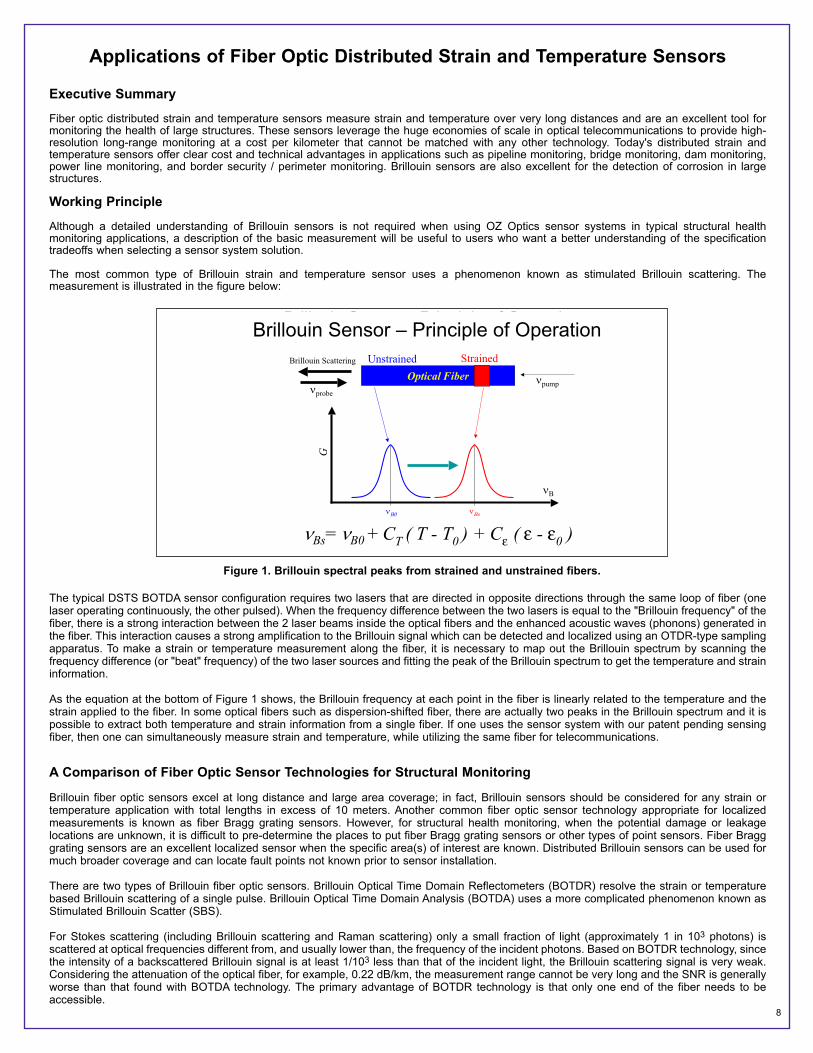
The most common type of Brillouin strain and temperature sensor uses a phenomenon known as stimulated Brillouin scattering. Themeasurement is illustrated in the figure below:
The typical DSTS BOTDA sensor configuration requires two lasers that are directed in opposite directions through the same loop of fiber (onelaser operating continuously, the other pulsed). When the frequency difference between the two lasers is equal to the "Brillouin frequency" of thefiber, there is a strong interaction between the 2 laser beams inside the optical fibers and the enhanced acoustic waves (phonons) generated inthe fiber. This interaction causes a strong amplification to the Brillouin signal which can be detected and localized using an OTDR-type samplingapparatus. To make a strain or temperature measurement along the fiber, it is necessary to map out the Brillouin spectrum by scanning thefrequency difference (or "beat" frequency) of the two laser sources and fitting the peak of the Brillouin spectrum to get the temperature and straininformation.
As the equation at the bottom of Figure 1 shows, the Brillouin frequency at each point in the fiber is linearly related to the temperature and thestrain applied to the fiber. In some optical fibers such as dispersion-shifted fiber, there are actually two peaks in the Brillouin spectrum and it ispossible to extract both temperature and strain information from a single fiber. If one uses the sensor system with our patent pending sensingfiber, then one can simultaneously measure strain and temperature, while utilizing the same fiber for telecommunications.
A Comparison of Fiber Optic Sensor Technologies for Structural Monitoring
Brillouin fiber optic sensors excel at long distance and large area coverage; in fact, Brillouin sensors should be considered for any strain ortemperature application with total lengths in excess of 10 meters. Another common fiber optic sensor technology appropriate for localizedmeasurements is known as fiber Bragg grating sensors. However, for structural health monitoring, when the potential damage or leakagelocations are unknown, it is difficult to pre-determine the places to put fiber Bragg grating sensors or other types of point sensors. Fiber Bragggrating sensors are an excellent localized sensor when the specific area(s) of interest are known. Distributed Brillouin sensors can be used formuch broader coverage and can locate fault points not known prior to sensor installation.
There are two types of Brillouin fiber optic sensors. Brillouin Optical Time Domain Reflectometers (BOTDR) resolve the strain or temperaturebased Brillouin scattering of a single pulse. Brillouin Optical Time Domain Analysis (BOTDA) uses a more complicated phenomenon known asStimulated Brillouin Scatter (SBS).
For Stokes scattering (including Brillouin scattering and Raman scattering) only a small fraction of light (approximately 1 in 103 photons) isscattered at optical frequencies different from, and usually lower than, the frequency of the incident photons. Based on BOTDR technology, sincethe intensity of a backscattered Brillouin signal is at least 1/103 less than that of the incident light, the Brillouin scattering signal is very weak.Considering the attenuation of the optical fiber, for example, 0.22 dB/km, the measurement range cannot be very long and the SNR is generallyworse than that found with BOTDA technology. The primary advantage of BOTDR technology is that only one end of the fiber needs to beaccessible.
Brillouin Sensor – Principle of Operation
B
G
s
StrainedUnstrainedOptical Fiber
probepump
Bs= B0 + CT ( T - T0 ) + Cε ( ε - ε0 )
Brillouin Scattering
Figure 1. Brillouin spectral peaks from strained and unstrained fibers.
Brillouin Sensor – Principle of Operation
9
The BOTDA technique is significantly more powerful as it uses enhanced Brillouin scattering through two counter-propagating beams. Due tothe strong signal strength the strain and temperature measurements are more accurate and the measuring range is longer than that of BOTDRtechnology. In addition, our patented sensing method allows one to determine simultaneous strain and temperature information.
The BOTDA method requires more optical components and a 2-way optical path so the total system cost is typically higher (the sensor fiber mustbe looped or mirrored). However, most field units deployed today are BOTDA systems because the additional measurement accuracy more thanjustifies the moderate increase in system cost.
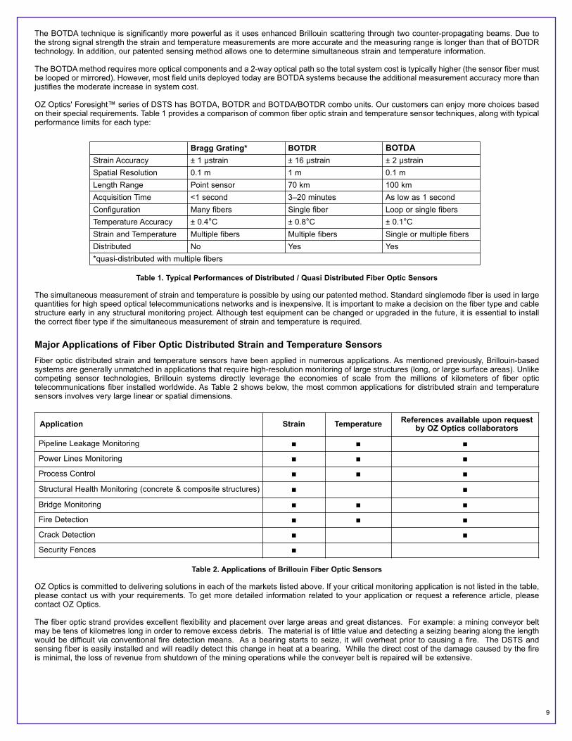
OZ Optics' Foresight™ series of DSTS has BOTDA, BOTDR and BOTDA/BOTDR combo units. Our customers can enjoy more choices basedon their special requirements. Table 1 provides a comparison of common fiber optic strain and temperature sensor techniques, along with typicalperformance limits for each type:
Table 1. Typical Performances of Distributed / Quasi Distributed Fiber Optic Sensors
The simultaneous measurement of strain and temperature is possible by using our patented method. Standard singlemode fiber is used in largequantities for high speed optical telecommunications networks and is inexpensive. It is important to make a decision on the fiber type and cablestructure early in any structural monitoring project. Although test equipment can be changed or upgraded in the future, it is essential to installthe correct fiber type if the simultaneous measurement of strain and temperature is required.
Major Applications of Fiber Optic Distributed Strain and Temperature SensorsFiber optic distributed strain and temperature sensors have been applied in numerous applications. As mentioned previously, Brillouin-basedsystems are generally unmatched in applications that require high-resolution monitoring of large structures (long, or large surface areas). Unlikecompeting sensor technologies, Brillouin systems directly leverage the economies of scale from the millions of kilometers of fiber optictelecommunications fiber installed worldwide. As Table 2 shows below, the most common applications for distributed strain and temperaturesensors involves very large linear or spatial dimensions.
Table 2. Applications of Brillouin Fiber Optic Sensors
OZ Optics is committed to delivering solutions in each of the markets listed above. If your critical monitoring application is not listed in the table,please contact us with your requirements. To get more detailed information related to your application or request a reference article, pleasecontact OZ Optics.
The fiber optic strand provides excellent flexibility and placement over large areas and great distances. For example: a mining conveyor beltmay be tens of kilometres long in order to remove excess debris. The material is of little value and detecting a seizing bearing along the lengthwould be difficult via conventional fire detection means. As a bearing starts to seize, it will overheat prior to causing a fire. The DSTS andsensing fiber is easily installed and will readily detect this change in heat at a bearing. While the direct cost of the damage caused by the fireis minimal, the loss of revenue from shutdown of the mining operations while the conveyer belt is repaired will be extensive.
Bragg Grating* BOTDR BOTDAStrain Accuracy ± 1 µstrain ± 16 µstrain ± 2 µstrainSpatial Resolution 0.1 m 1 m 0.1 mLength Range Point sensor 70 km 100 kmAcquisition Time <1 second 3–20 minutes As low as 1 secondConfiguration Many fibers Single fiber Loop or single fibersTemperature Accuracy ± 0.4°C ± 0.8°C ± 0.1°CStrain and Temperature Multiple fibers Multiple fibers Single or multiple fibersDistributed No Yes Yes*quasi-distributed with multiple fibers
Application Strain Temperature References available upon requestby OZ Optics collaborators
Pipeline Leakage Monitoring ■ ■ ■
Power Lines Monitoring ■ ■ ■
Process Control ■ ■ ■
Structural Health Monitoring (concrete & composite structures) ■ ■
Bridge Monitoring ■ ■ ■
Fire Detection ■ ■ ■
Crack Detection ■ ■
Security Fences ■
10
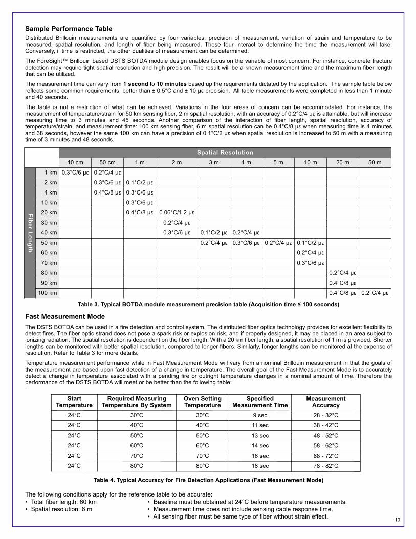
Sample Performance TableDistributed Brillouin measurements are quantified by four variables: precision of measurement, variation of strain and temperature to bemeasured, spatial resolution, and length of fiber being measured. These four interact to determine the time the measurement will take.Conversely, if time is restricted, the other qualities of measurement can be determined.
The ForeSight™ Brillouin based DSTS BOTDA module design enables focus on the variable of most concern. For instance, concrete fracturedetection may require tight spatial resolution and high precision. The result will be a known measurement time and the maximum fiber lengththat can be utilized.
The measurement time can vary from 1 second to 10 minutes based up the requirements dictated by the application. The sample table belowreflects some common requirements: better than ± 0.5°C and ± 10 µε precision. All table measurements were completed in less than 1 minuteand 40 seconds.
The table is not a restriction of what can be achieved. Variations in the four areas of concern can be accommodated. For instance, themeasurement of temperature/strain for 50 km sensing fiber, 2 m spatial resolution, with an accuracy of 0.2°C/4 µε is attainable, but will increasemeasuring time to 3 minutes and 45 seconds. Another comparison of the interaction of fiber length, spatial resolution, accuracy oftemperature/strain, and measurement time: 100 km sensing fiber, 6 m spatial resolution can be 0.4°C/8 µε when measuring time is 4 minutesand 38 seconds, however the same 100 km can have a precision of 0.1°C/2 µε when spatial resolution is increased to 50 m with a measuringtime of 3 minutes and 48 seconds.
Table 3. Typical BOTDA module measurement precision table (Acquisition time ≤ 100 seconds)
Fast Measurement ModeThe DSTS BOTDA can be used in a fire detection and control system. The distributed fiber optics technology provides for excellent flexibility todetect fires. The fiber optic strand does not pose a spark risk or explosion risk, and if properly designed, it may be placed in an area subject toionizing radiation. The spatial resolution is dependent on the fiber length. With a 20 km fiber length, a spatial resolution of 1 m is provided. Shorterlengths can be monitored with better spatial resolution, compared to longer fibers. Similarly, longer lengths can be monitored at the expense ofresolution. Refer to Table 3 for more details.
Temperature measurement performance while in Fast Measurement Mode will vary from a nominal Brillouin measurement in that the goals ofthe measurement are based upon fast detection of a change in temperature. The overall goal of the Fast Measurement Mode is to accuratelydetect a change in temperature associated with a pending fire or outright temperature changes in a nominal amount of time. Therefore theperformance of the DSTS BOTDA will meet or be better than the following table:
Table 4. Typical Accuracy for Fire Detection Applications (Fast Measurement Mode)
The following conditions apply for the reference table to be accurate:• Total fiber length: 60 km • Baseline must be obtained at 24°C before temperature measurements.• Spatial resolution: 6 m • Measurement time does not include sensing cable response time. • All sensing fiber must be same type of fiber without strain effect.
Spatial Resolution10 cm 50 cm 1 m 2 m 3 m 4 m 5 m 10 m 20 m 50 m
Fiber Length
1 km 0.3°C/6 µε 0.2°C/4 µε
2 km 0.3°C/6 µε 0.1°C/2 µε
4 km 0.4°C/8 µε 0.3°C/6 µε
10 km 0.3°C/6 µε
20 km 0.4°C/8 µε 0.06°C/1.2 µε
30 km 0.2°C/4 µε
40 km 0.3°C/6 µε 0.1°C/2 µε 0.2°C/4 µε
50 km 0.2°C/4 µε 0.3°C/6 µε 0.2°C/4 µε 0.1°C/2 µε
60 km 0.2°C/4 µε
70 km 0.3°C/6 µε
80 km 0.2°C/4 µε
90 km 0.4°C/8 µε
100 km 0.4°C/8 µε 0.2°C/4 µε
StartTemperature
Required Measuring Temperature By System
Oven SettingTemperature
SpecifiedMeasurement Time
Measurement Accuracy
24°C 30°C 30°C 9 sec 28 - 32°C
24°C 40°C 40°C 11 sec 38 - 42°C
24°C 50°C 50°C 13 sec 48 - 52°C
24°C 60°C 60°C 14 sec 58 - 62°C
24°C 70°C 70°C 16 sec 68 - 72°C
24°C 80°C 80°C 18 sec 78 - 82°C

11
Calculating the Cost Savings for Brillouin Fiber Optic Sensors
As stated previously, Brillouin fiber sensors offer high-resolution with long distance coverage at a cost per kilometer unmatched by any othermeasurement technique. This creates the opportunity to generate a rapid return on investment for Brillouin sensor-based monitoring systemsused in critical monitoring applications. The figure below shows a simple cost savings example:
Table 5. Cost Savings example
Several pipeline shutdown accidents demonstrate the need for continuous online monitoring. While the calculation in Table 5 is for a mid-sizedregional distribution pipeline, the economics for major pipelines are even more compelling. The shutdown cost per day can easily exceed $10 million. With long-haul Brillouin monitoring system costs of only $1 - $2 per meter, the prevention of a single shutdown greatly exceeds theinstallation and operating costs of a monitoring system. Other large structures such as power lines, dams, and bridges also have very high costsassociated with catastrophic failure and shutdowns.
The most important factors in a typical cost savings estimate are the reduction in maintenance/inspection cost (due to automated monitoring),the reduction in downtime, and the reduction in the potential for catastrophic failure. In many instances, the downtime and failure costs are muchhigher than that shown in the example.
For more information about our strain and temperature sensor system and related products, please visit www.ozoptics.com.
Background ArticlesPipeline Buckling Detection:L. Zou, X. Bao, F. Ravet, and L. Chen, “Distributed Brillouin fiber sensor for detecting pipeline buckling in an energy pipe under internal pressure,"Applied Optics 45, 3372-3377 (2006).Pipeline Corrosion Detection:L. Zou, G. Ferrier, S. Afshar, Q. Yu, L. Chen, and X. Bao, “Distributed Brillouin scattering sensor for discrimination of wall-thinning defects in steel pipeunder internal pressure,” Applied Optics 43, 1583-1588 (2004).
Power Line Monitoring:L. Zou, X. Bao, Y. Wan and L. Chen, “Coherent probe-pump-based Brillouin sensor for centimeter-crack detection,” Optics Letters 30, 370-372 (2005).Crack Detection:L. Zou and Maria Q. Feng, “Detection of micrometer crack by Brillouin-scattering-based distributed strain and temperature sensor,” 19th InternationalConference on Optical Fiber Sensors, Perth (Australia, 14-18 April 2008).Accuracy of BOTDA Technology:L. Zou, X. Bao, S. Yang, L. Chen, and F. Ravet, “Effect of Brillouin slow light on distributed Brillouin fiber sensors,” Optics Letters 31, 2698-2700 (2006)Simultaneous Measurement of Strain and Temperature:L. Zou, X. Bao, S. Afshar V., and L. Chen, “Dependence of the Brillouin frequency shift on strain and temperature in a photonic crystal fiber,” OpticsLetters 29, 1485-1487 (2004)
Fiber Optic MonitoringOZ Optics Ltd. Cost Savings Calculator
System ParametersPipeline Length 50 kmCost of Failure $750,000 cost of leakDowntime Cost $20,000 per hour
Comparison Monitoring No Monitoring Comments
Probability of Failure % / year 0.25% 1% Reduced risk of failure
Downtime hours/year 4.8 24 Automated preventive maintenance
Maintenance Cost dollars/year $25,000 $50,000 Automation of routine maintenance
Total Annual Savings $414,625 Total Annual Savings