Fibre optic connectors a different “view” - UCL …discovery.ucl.ac.uk/554010/2/Seafom...
44
Fibre optic connectors – a different “view” Dr David R. Selviah Department of Electronic and Electrical Engineering, University College London, UCL, UK, [email protected] and Richard C. A. Pitwon Xyratex Technology Ltd, Havant, UK, [email protected] with thanks to Ton Bolhaar and Michiel Boermans, Tyco Electronics, [email protected] SEAFOM- Subsea Fibre Optic Monitoring Group, Westbury Hotel, Dublin, Ireland, 7th December 2010 © UCL 2010
Transcript of Fibre optic connectors a different “view” - UCL …discovery.ucl.ac.uk/554010/2/Seafom...

Fibre optic connectors – a different “view”
Dr David R. Selviah
Department of Electronic and Electrical Engineering,
University College London, UCL, UK, [email protected]
and
Richard C. A. Pitwon
Xyratex Technology Ltd, Havant, UK, [email protected]
with thanks to
Ton Bolhaar and Michiel Boermans, Tyco Electronics,
SEAFOM- Subsea Fibre Optic Monitoring Group, Westbury Hotel, Dublin, Ireland, 7th December 2010
© UCL 2010

Presentation Outline
1. Alignment and Insertion Loss
2. Overview of Optical Fibre Connectors
• Standard connectors
• Multiple fibre connectors
• Rugged connectors
• Active optical cable assemblies
3. Active multiple channel connectors
2

Information is Tyco Electronics Confidential & Proprietary
Do Not Reproduce or Distribute page 3 /
Attenuation
Eccentricities:
Ferrule
SurfaceFerrule Centre
(=Reference)
Epoxy
Hole
Centre
Fibre
Core
Fibre
Fibre
Geometric
Centre
Eccentricities:
Ferrule
SurfaceFerrule Centre
(=Reference)
Epoxy
Hole
Centre
Fibre
Core
Fibre
Fibre
Geometric
Centre
Air gap Angle
Core Offset
Air gap Angle
Core Offset
Insertion Loss = -10 x 10log { Pt /Po }
Return Loss = -10 x 10log { Pr /Po }
Po
Pr
Pt

Information is Tyco Electronics Confidential & Proprietary
Do Not Reproduce or Distribute page 4 /
Return Loss
• PC (Physical Contact):
– Low Insertion Loss (0.2 dB typ.)
– Return Loss:
• Mated > 45 dB
> 55 dB (Ultra PC)
• Un-mated ~ 15 dB
• APC (Angled Physical Contact):
– Low Insertion Loss (0.2 dB typ.)
– Return Loss:
• Mated: 70..80 dB typ.
• Un-mated: > 60 dB
FF
F = 8 - 12 N
Alignment Sleeve
Ferrule Optical Fibre
Reflection
Angle

SC Connector
• Subscriber Connector, Square Connector, Standard Connector
• Push pull connector
• Pre-Radiused, Full 2.5 mm Ceramic Ferrule
• Tuneable, 4 positions for Lowest Losses
• PC or APC end facet
• Multimode or Single mode
• Simplex & Duplex Versions
• Wide Range of Cable Diameters
• 900 μm buffer
• 1.6 - 2.0, 2.4 & 3 mm
• Polymer and Metal rear body design
• Standards IEC 61754-4, TIA/EIA 568B & GR326
• Applications: Telecom, Datacom, CATV, Industrial 5

LC Connector • Lucent Connector or Local Connector
• Small Form Factor (SFF), push pull connection
• Reduces equipment space by 50%
• Full 1.25 mm Ceramic Ferrule
• RJ 45 based design
• PC or APC end facet
• Multimode or Single mode
• Simplex & Duplex Versions
• Field installable duplex clip
• Secure Versions (Colour & Key coded)
• Standard IEC 61754-20
• Applications: Computer & Transmission Equipment Manufacturers,
Telecoms, Industrial, High-density connections, SFP transceivers, XFP
transceivers. 6

Ultra-short LC
• Ultra Short LC design (37 mm) when standard LC is 52 mm
• Accommodating cable diameter 1.8 - 2 mm
• Shortest design
• Single mode and Multimode
• Separate Simplex & Duplex thumb latch
• Bend Limiting Boot
– Preventing signal losses due to sharp cable bends / kinks
• Applications
– Front I/O cabling
– Racks with Front doors
– Restricted Space Areas
7

Variety of designs for all applications
8
Short 42
mm boot
Low Cost
Angled
Short Buffer Bend Limiting
Buffer
Right Angle
3.0 mm
Cable
Bend Limiting

MU Connector
• Miniature Unit
• Half the size of the SC Connector
• Push Pull design
• Full Ceramic 1.25 mm Ferrule
• PC end facet
• Single mode
• Tuneable
• Primarily used in Asia
• Standard IEC 61754-6
• Applications: Telecom, CATV, Data 9

FC Connector
• Ferrule Connector or Fibre Channel
• Threaded coupling nut for secure connection
• Single Piece Rugged Connector Body
• PC or APC end facet
• Full Ceramic Ferrule, 2.5 mm
• Single mode or Multimode
• Standard IEC 61754-13
• Applications: Datacom, Telecom, single-
mode lasers, CATV, Instrumentation, Widely
used eg. UK & Indian Telecom Networks
10

ST Connectors
• Straight Tip
• Bayonet connection
• Only PC end facet
• Multimode or rarely Single mode
• Ferrule options: Full Ceramic, Stainless
Steel (SS), Polymer
• Different Hole size options in SS :
• – 125, 140, 231, 240, 280 μm
• Nut options: Stainless Steel, Polymer
• Standard IEC 61754-2
• Applications: Industrial, Military, Medical
11

MT Connector
• Mechanical Transfer
• Push pull connection
• 2.5 mm × 6.4 mm
• Two alignment pins
• Available in pre-terminated cable assemblies
• Applications: outdoors
12

MPO/MTP and MPX Multi-Fibre Interconnects • Multiple Fibre Push On/ Pull Off
• Push pull connection
• Free floating for system reliability
• Based on industry proven MT
technology
• Blindmate backplane solution
• Both multimode (62.5/125 μm or
50/125μm) and single mode (9 μm)
fibre
• Standard IEC-61754-7
• Applications: indoor interconnects
13
PARA-OPTIXTM Higher Density Ferrules
6 rows of 12 fibres = 72 positions

PARA-OPTIXTM Cable Assemblies
• Industry Standard MTP/MPO
Connector
• Up To 72 Fibres
• Multimode Only
• Use Anywhere MPO Is Used:
– Backplane
– Front-panel I/O
• Telcordia Testing
– 108-2175 Product Spec.
– 501-626 Test Report
14
Original 12 fibre
24 fibres ( 2 rows of 12)
72 fibre (6 rows of 12)

Information is Tyco Electronics Confidential & Proprietary
Do Not Reproduce or Distribute page 15 /
Rugged Fiber Optic Connectors
Fiber Ball lens
Expanded
Beam
Connector

Sealed Industrial Rugged ODVA Compliant
Duplex LC
• IP67 Rated - Protection from dust
and water immersion
• LC qualified to Telcordia GR-326
and TIA/EIA 568B.3
• Temperature – 40 to 85°C
• Bayonet-style mechanical lock
• Flame retardant UL 94 V-0
• Redundant interfacial, cable, and
panel seals
• Single mode and multimode fibre
16

Outdoor Connector • Fibre Optic Cable assembly
with an industry standard
copper interface
• Easy to Install
• One hand blind mating possible
• Easy to clean
• Waterproof
• Dustproof
• Corrosion resistant
• EMI Shielded.
• IP 68
• Light Weight
• Low Cost
• Low Insertion Loss
• Longer Reach 17
Duplex Version
Quad Version

Information is Tyco Electronics Confidential & Proprietary
Do Not Reproduce or Distribute page 18 /
Outdoor IP67 Sealing System: FULLAXS
Information is Tyco Electronics Confidential & Proprietary
Do Not Reproduce or Distribute
Applications
• Fiber To The Antenna
– Remote Radios
– BTS
• Industrial
• Other Outdoor applications
Features & Benefits
• „Open“ Bulkhead: Easy direct access to SFP access for repair or upgrade
• Bayonet Locking, IP 67 Sealing: Quick & Easy handling returns Low Applied Cost
• No internal pigtail required for coupling to SFP: Reduces Sytem Cost
• Based on standard LC platform: Proven interface & wide range of SFP TxRx‘s
• Free Z-Axis with full float: Accepting all known SFP‘s, No stress on Fibers & Cable
• Easy Bulkhead (X-Y) Positioning : Allows wide tolerance on SFP position
• Will also accomodate RJ45 etc.: One System fits all
Optical LC-Duplex
Electrical RJ45

Information is Tyco Electronics Confidential & Proprietary
Do Not Reproduce or Distribute page 19 /
Imagine…. Having one of the following
problems
• Real estate of present location is full and needs
to be expanded
• Cable lengths would need to exceed 50 m
• Costs for new real estate would be too high
• EMI of all cables would exceed limits
• Too much cable weight
• Air flow problems
• Forced cable bending
R2
R1
R1 = 25 mm << R2

Active Optical Cable Assemblies
• Applications:
• Super Computers
• Cluster Computers
• High End Servers
• Mass Storage
• Metro Network Switch /
Cross Connect
• High End Carrier Class
Routers
20

PARALIGHT Active Optical Cable Assemblies
• Optical Fibre with electro-optic
components
• No Equipment Upgrades
• Functions like a Standard
Electrical Cable
• 100 Metres Plus Reach
• Low Latency
• No EMI
• Hot Pluggable
• 1/3 Size of Copper Cable
• 1/10th weight copper cable
• 3.0 mm O.D. Round: flexible
• Low Power!
• Increased Air Flow 21
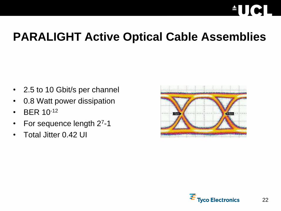
PARALIGHT Active Optical Cable Assemblies
• 2.5 to 10 Gbit/s per channel
• 0.8 Watt power dissipation
• BER 10-12
• For sequence length 27-1
• Total Jitter 0.42 UI
22

23
Design and performance constraints
Optical Backplanes in Data Storage Applications R. Pitwon

24
0.25 mm 0.25 mm
1.5 mm 1.5 mm
0.5
mm
18 optical channels
0.5
mm
1 electronic channel
Interconnect density comparison
Density of copper interconnect
Based on design rules for 10 Gb/s
1.5 mm horizontal spacing
0.5 mm vertical spacing
Density of optical interconnect
Based on MTP standard
250 μm horizontal and vertical
spacing
18 fold density increase
Optical Backplanes in Data Storage Applications R. Pitwon

25
Optical layout advantages
Splitters
Optical power splitters
Branch number dependent
on link budget
Crossovers
Signal crossovers on one
layer
Different crossover angles
possible
Optical Backplanes in Data Storage Applications R. Pitwon

26
Polymer Multimode Waveguide Interconnects
Copyright © 2010 UCL
Straight waveguides – Optical InterLinks 90° Crossings – Dow Corning
90° Crossings – Heriot Watt University 50° Crossings – Exxelis
Waveguide cores – Exxelis

27 27
Fully Interconnected System Demonstrator
Fully connected waveguide layout using design rules
Copyright © 2010 UCL

29 Copyright © 2010 UCL
Waveguide with 2 Crossings Connected 1st
to 3rd Linecard Interconnect

31
Xyratex Electro-Optical Midplane
Optical Backplanes in Data Storage Applications R. Pitwon

32
Backplane Lens
Interface
Parallel optical
transceiver
Connector
housing
Copper layers
FR4 layers
Optical layer
Optical backplane connection architecture
Orthogonal docking
Optical Backplanes in Data Storage Applications R. Pitwon

33
VCSELs PINs
Optical backplane connection architecture
Single waveguide
illuminated
Butt-coupled in-plane connection
Optical Backplanes in Data Storage Applications R. Pitwon

34
MT pins
Drivers
Optical
platform
Microlens array
plate
Mechanically flexible optical platform
MT compatible optical interface
Geometric microlens array
Quad VCSEL driver and TIA/LA
VCSEL / PIN arrays on pre-aligned frame
Parallel optical transceiver
Optical Backplanes in Data Storage Applications R. Pitwon

35
Spring loaded platform Microcontroller
Active pluggable connector
Parallel optical transceiver Connector module
Optical Backplanes in Data Storage Applications R. Pitwon

36
Two stage connection mechanism
First stage
Peripheral card inserted into midplane
Second stage
Optical platform pushed forward
Butt-coupled in-plane interface
Optical Backplanes in Data Storage Applications R. Pitwon

37
Undocked
Cam track
Docked
Ramped
plug
Connector engagement mechanism
Cam
followers
Optical Backplanes in Data Storage Applications R. Pitwon

38
VCSEL
λ = 850nm
Ø = 7μm
Div = 25º
PIN
λ = 850nm
Ø = 70μm
Interface loss: 0.72 dB
Interface loss: 1.11 dB
Optimised for loss minimisation
Maximum beam expansion
Polymer waveguides
Ø = 70μm x 70μm
ncore = 1.56
ncladding = 1.524
NA = 0.33
Dual lens coupling interface
Free space coupling
Beam expansion at coupling interface
Reduces susceptibility to contamination
Dual lens coupling solution
Optical Backplanes in Data Storage Applications R. Pitwon

39
Optical polymer
Low loss at 850 nm
Waveguide
characteristics
ncore = 1.56
ncladding = 1.524
∆n = 2.3%
N.A. = 0.33
Core dimensions
Ø = 70 μm x 70 μm
Electro-optical midplane
Optical Backplanes in Data Storage Applications R. Pitwon

40
Peripheral test cards
XFP front end
8 x 8
crosspoint
switch
FPGA
Array
connector
PCI bridge
C-PCI
connector
Optical
connector site
Optical Backplanes in Data Storage Applications R. Pitwon

41
Demonstration platform
Single board
computer
Peripheral
test card
Compact PCI
chassis
Pluggable optical
connector
Electro-optical
midplane

42
Target test card
Electro-optical midplane
High speed data transmission measurements
10 GbE LAN test data
Injected into front end
Pluggable connectors
Polymer waveguides
1st test card
Retrieved through front end
Signal integrity measured
Optical Backplanes in Data Storage Applications R. Pitwon

43
High speed data transmission measurements
Data rate: 10.3 Gb/s
Typical Pk to Pk jitter: 26 ps
Test data captured on 8 waveguides
BERT on waveguides
Measured on all waveguides
BER less than 10-12 measured
Optical Backplanes in Data Storage Applications R. Pitwon

Acknowledgments
• University College London, UK
– Kai Wang, Hadi Baghsiahi, F. Aníbal Fernández, Ioannis Papakonstantinou
• Tyco Electronics
– Ton Bolhaar and Michiel Boermans
• Xyratex Technology Ltd., UK
– Dave Milward, Ken Hopkins, Malcolm Muggeridge
• Heriot Watt University
– Andy C. Walker, Aongus McCarthy, Himanshu Suyal
• Stevenage Circuits Ltd. (SCL), UK
– Dougal Stewart, Jonathan Calver, Jeremy Rygate, Steve Payne, Witold Kandulski
• Exxelis Ltd
– Navin Suyal, Habib Rehman
• Dow Corning
– Dave DeShazer, Jon DeGroot
• Cadence
– Gary Hinde, Martin Cole
• Optical Interlinks
– Bruce Booth
• EPSRC, IeMRC and all partner companies for funding + IBM Zurich for fabrication
44 © UCL 2010