Fibre Optic Communications - Introductionsro.sussex.ac.uk/id/eprint/68292/1/Lecture1v3 2017.pdf ·...
146
1 Fibre Optic Communications - Introduction Professor Chris Chatwin Module: Fibre Optic Communications MSc/MEng – Digital Communication Systems UNIVERSITY OF SUSSEX SCHOOL OF ENGINEERING & INFORMATICS 1 st June 2017
Transcript of Fibre Optic Communications - Introductionsro.sussex.ac.uk/id/eprint/68292/1/Lecture1v3 2017.pdf ·...

1
Fibre Optic Communications -
Introduction
Professor Chris ChatwinModule: Fibre Optic Communications
MSc/MEng – Digital Communication Systems
UNIVERSITY OF SUSSEXSCHOOL OF ENGINEERING & INFORMATICS 1st June 2017

Problems to be avoided

DWDM Optical Fibre Communications
- Capacity: 7.1 terabytes per second Dec 2007
Global Data Integration Technology

crciimsoc040101 5
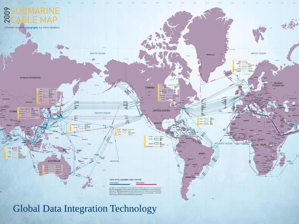
International Bandwidth 2012
crciimsoc040101 6

International Bandwidth 2014
crciimsoc040101 7

USED INTERNATIONAL BANDWIDTH
GROWTH BY REGION, 2014-2021
crciimsoc040101 8

MEDIAN 10 GIGE IP TRANSIT PRICES IN
MAJOR CITIES, Q2 2012-Q2 2015
crciimsoc040101 9

Arctic Fibre is deploying state of the art technology utilizing
100 gigabit wavelengths to construct a system with a capacity
of 24 terabits/s.
crciimsoc040101 10
The construction of the system is beginning in May 2014
and is scheduled to be in service in January 2016.
Repeater
every 60km

crciimsoc040101 12

VSAT
crciimsoc040101 13

crciimsoc040101 14

Construction cost of submarine
cables, 1998-2011

The Global Fibre Backbone
integrates global communications

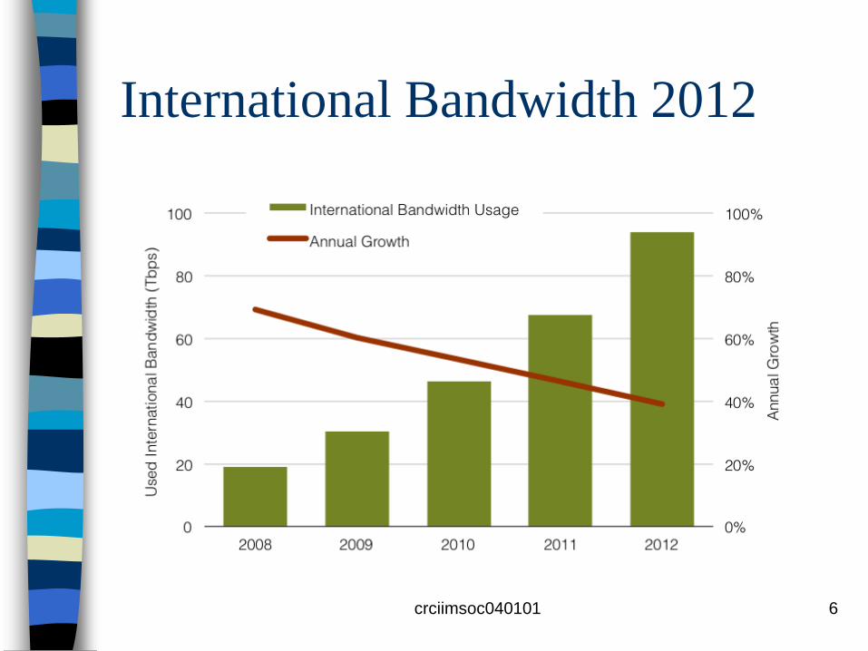
Ground-Based Electro-Optical Deep Space
Surveillance (GEODSS) - Diego Garcia / Maui /
Socorro (check orange arrows on previous slide)
• Primary Mission: Space Surveillance
• Supports Air Force Space Command
(AFSPC) as a dedicated Deep Space
(DS) sensor
• GEODSS brings together the
telescope, low-light-level cameras, and
computers
GEODSS Telescopes – Maui, Hawaii

Inside Diego Garcia GEODSS

Global Data Integration Technology

Space Surveillance
•Conduct space surveillance from space
•Surveillance of entire geosynchronous belt
•Assured access to objects of military interest
• Provides up to date satellite orbital elements to
Fleet and Fleet Marine forces
• Supports US Space Command as part of
nation’s worldwide Space Surveillance Network
NAVSPACE Fence

Ubiquitous Sonar Surveillance Systems
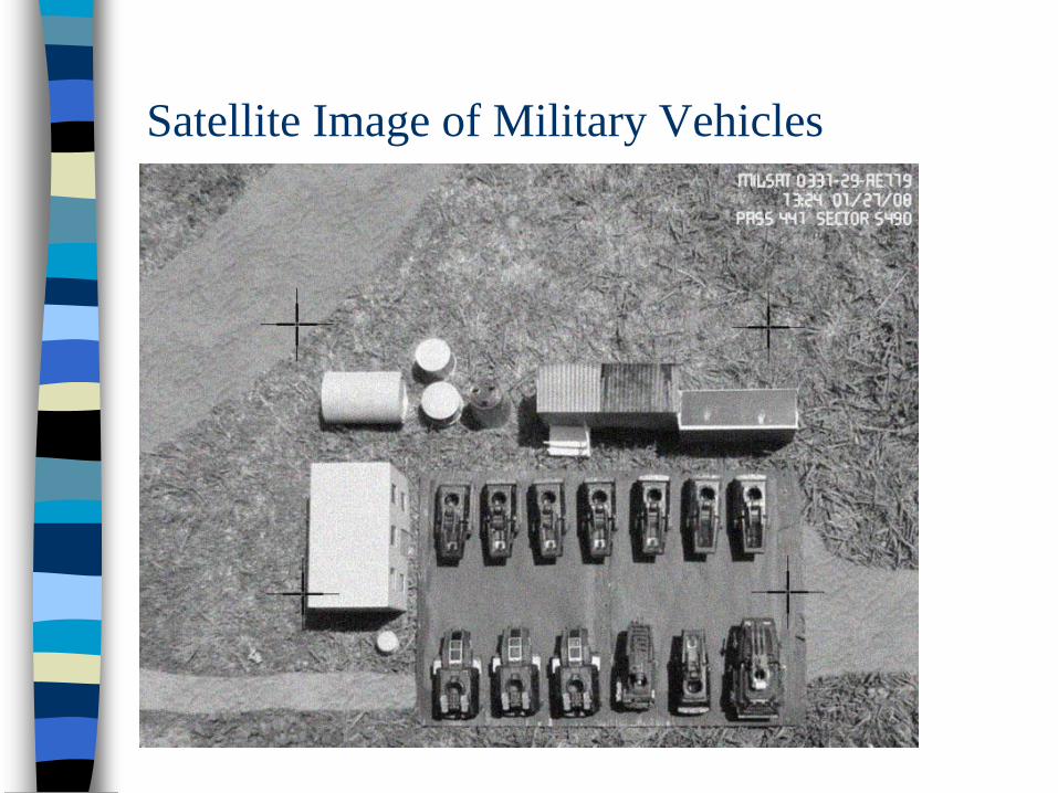
Satellite Image of Military Vehicles

As Important as the WheelA graduate of Woolwich Polytechnic won the
Nobel Prize for Physics. Charles Kuen Kao’s
work with fibre optics paved the way for
lightning-fast broadband.
Professor Kao was honoured for his
breakthroughs involving the transmission of
light in fibre optics.
He was the first person to develop efficient
fibre-optic cables and as a result of his work
more than a billion kilometres of optical
cables carry super-fast broadband internet
data to and from households and offices
around the world.

GCHQ
GCHQ's headquarters are in
Cheltenham,
Gloucestershire. There are
two much smaller sites in
Cornwall and Yorkshire but
most of the 5500 staff work at
the impressive state of the
art building at Benhall in
Cheltenham.

Trans-Atlantic Fibre Optic Cables
http://www.submarinecablemap.com/

The Intelsat Satellite Network
2008

Very Small Aperture Terminal
(VSAT)
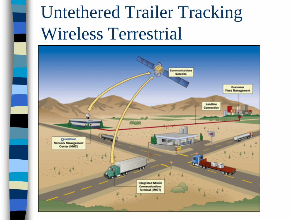
Untethered Trailer Tracking
Wireless Terrestrial
Communications
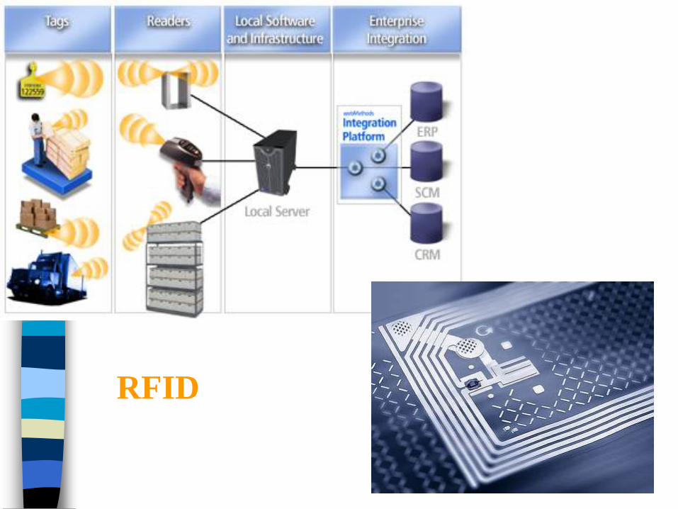
RFID

Intelsat GXS® Fiber Network
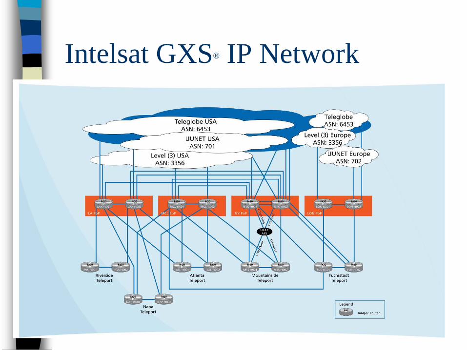
Intelsat GXS® IP Network

Cisco Catalyst 6500 Series Switches/Routers -
Integration Technology for Security Systems

Evolution of All Optical
Communication Network
a) Point to Point Links
b) Optical domain multiplexing
c) Photonic switching
d) Photonic computing

4 x 4 electro-optic photonic
switch

MEMS Mirrors

Glimmerglass Intelligent Optical Switch
System 600
32x32 - 192x192
• Handles all traffic data rates:
10GE up to OC-768 and 100GE
• Transparently accepts all
signal formats: SONET/SDH,
Ethernet, DWDM, digital, or
analog
• Single-mode, wideband (1270
nm - 1630 nm)
• 20 Millisecond switching
• Compact, low-power, high-
density

Internet Peering Exchange via Optical
Switching – Integration Technology

Submarine fibre optic cables
crciimsoc040101 39

Optical Repeaters
crciimsoc040101 40
Wide bandwidth of 36nm
Supporting 10Gb/s x 128 wavelengths
Maximum capability of 12FPs
Low noise figure of 5dB
Highly-reliable new 980nm pump LDs
Supervisory (SV) function of active
Telecommand-Telemetry monitoring and
passive C-OTDR
Digital supervisory and telemetry signals
superimposed onto the optical traffic signal
Housed in a rugged, corrosion-resistant
casing
Designed for 25 years of operation at
depths down to 8,000m

crciimsoc040101 49
Communication Systems
An optical or lightwave communication
system uses light waves as the carrier for
transmission.
Figure 2 shows a point to point
communication system.
When transmission links are interconnected
with multiplexing or switching functions, figure
(1), they are called a communication network.

crciimsoc040101 50
Communication Network

crciimsoc040101 51
Communication Systems
Each communication link shown in figure 1
consists of three basic components:
– Transmitter
– Channel
– Receiver
See Figure 2, with optical systems the
channel noise is small but there is noise from
the transmitter (light source) and the optical
receiver

crciimsoc040101 52
Point-to-Point Transmission Link

crciimsoc040101 53
Transmitter and Receiver Blocks
A Transmitter consists of blocks
performing source coding, channel
coding, line coding, modulation and
signal amplification
A receiver may include blocks
performing equalisation, retiming,
detection, demodulation and decoding;
illustrated by figure 1.3

crciimsoc040101 54
Communication System
Compression
Error Control
Transmission
Line
Conditioning

crciimsoc040101 55
Digitised Image Transmission
Digitized image transmission consists of many bits eg 24 bits per pixel colour image of 1000 x 1000 pixels has 24 megabits or 3 megabytes of data
Source coding is frequently used to reduce the number of bits in transmission. Because source coding is liable to transmission errors, channel coding is often used to detect and correct error bits by adding extra parity check bits
In addition, line coding is used to achieve certain properties in the transmitted waveform, such as dc balance and sufficient transitions.

crciimsoc040101 56
Digitised Image Reception
At the receiver side, due to the added
noise and distortion from transmission,
an equalizer is used to maximise the
detection performance.
Bit timing synchronisation is used to
recover the original transmitter bit clock
for sampling and detecting the
transmitted bits.

crciimsoc040101 57
Transmission and Detection
Differences in communication systems
can be characterised in three ways:
1) Baseband versus passband
2) Analog versus digital
3) Coherent versus incoherent
detection

crciimsoc040101 58
Baseband versus Passband
If the signal is transmitted over its original
frequency band, the transmission is called
baseband transmission
If the signal is shifted to a frequency band
higher than its original baseband, it is called
passband transmission
Some baseband and passband signals are
illustrated in Figure 1.4

crciimsoc040101 59
Baseband and Passband Signals

crciimsoc040101 60
Shifting the baseband signal to a passband can be
achieved by multiplying the baseband by a high
frequency carrier.
Where m(t) is the baseband signal, cos(wct) is the
carrier and SAM(t) is called an amplitude modulated
passband signal because its amplidute is proportional
to the baseband signal, see figure 1.5
Passband
….1

crciimsoc040101 61
Amplitude Modulation
crciimsoc040101 62
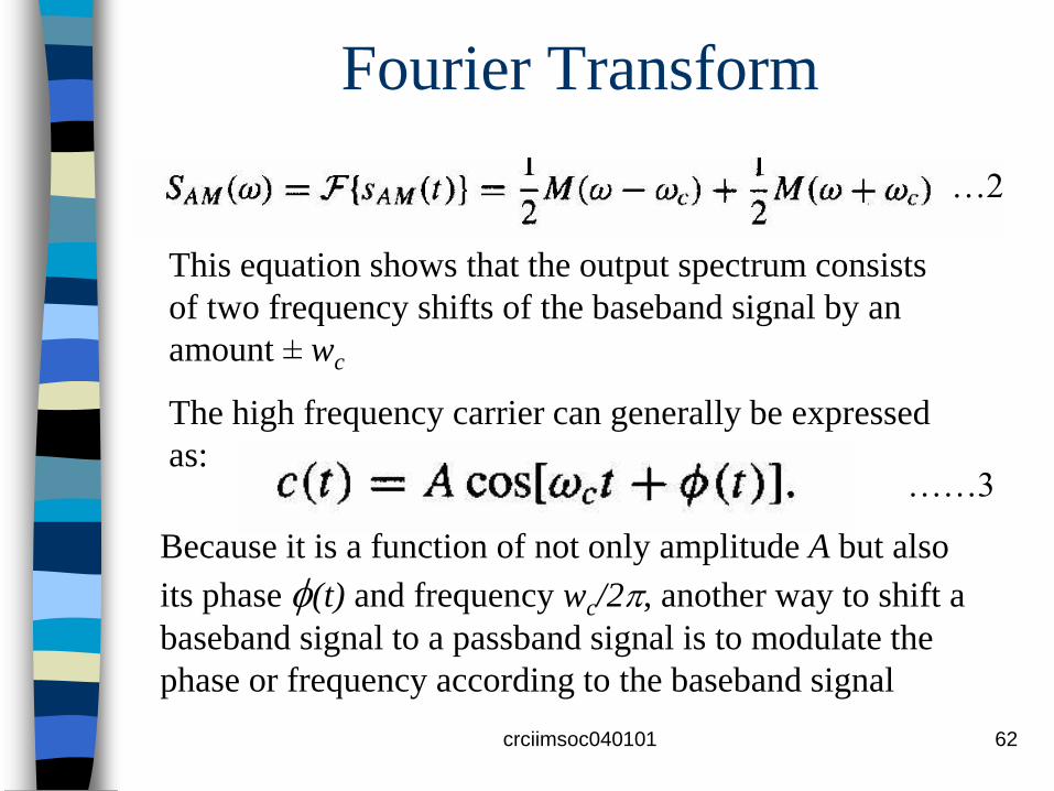
Fourier Transform
This equation shows that the output spectrum consists
of two frequency shifts of the baseband signal by an
amount ± wc
The high frequency carrier can generally be expressed
as:
Because it is a function of not only amplitude A but also
its phase (t) and frequency wc/2, another way to shift a
baseband signal to a passband signal is to modulate the
phase or frequency according to the baseband signal
…2
……3

crciimsoc040101 63
Frequency Modulation
In FM the instantaneous frequency of the
carrier f(t) is the sum of the fixed high
frequency term fc plus a small term
proportional to the baseband signal. That is,
an FM signal of the form:
…..4
…..5

crciimsoc040101 64
Frequency Modulation
Where the instantaneous frequency is by definition the time derivative of the phase divided by 2, and kFM is called the modulation index.
In contrast with AM signals, the amplitude or the envelope A of an FM signal is constant, but its instantaneous frequency moves up and down around fc
The amount of frequency deviation is determined by both the modulation index and input message signal.

crciimsoc040101 65
Why Passband?
Some transmission media have either a
large loss or high noise at low
frequencies; for example, optical fibres
have a cutoff frequency below which
electromagnetic waves have a high loss
Therefore, we need to convert a
baseband signal to a lightwave for
transmission over optical fibres

crciimsoc040101 66
Why Passband?
Another reason for passband transmission is to multiplex multiple signals into the same transmission medium.
For example, AM/FM radio and TV channels are multiplexed in the frequency domain by a process called frequency division multiplexing (FDM), where each channel is centred around a pre-assigned carrier frequency.
AM, FM, and TV are in the frequency ranges of 530-1700 kHz, 88-108 MHz, and 54-88 MHz plus 120-600 MHz, respectively

crciimsoc040101 67
Why Passband?
In optical communications, the carrier is in the visible or infrared frequency range
If the amplitude of a light signal is proportional to a baseband signal, the amplitude modulation is similar to that in AM/FM radio
As in radio, one can multiplex several optical signals of different carrier frequencies into the same fibre
Multiplexing in the frequency domain allows multiple transmissions at the same time
This same FDM technique in optical communications is called wavelength division multiplexing (WDM)

crciimsoc040101 68
Sub-carrier Multiplexing
FDM is frequently done in several
hierarchical layers. This is called sub-
carrier multiplexing (SCM).
In the case of optical communications,
the first step of frequency multiplexing is
in the radio frequency (RF) domain. The
combined radio signal is used to
modulate a light carrier.

crciimsoc040101 69
Video transmission over optical
fibres
Cable TV signals are traditionally amplitude modulated and frequency multiplexed over the 54-600 MHz band
As optical fibre transmission has become more cost effective, many cable operators have used video transmission over fibres in video signal distribution
To transmit these analogue video signals that have already been multiplexed in the RF domain, SCM is a natural choice.

crciimsoc040101 70
Video transmission over optical
fibres
In this approach the multiplexed RF signal
directly modulates the output light intensity of
a laser diode
This sub-carrier modulation is illustrated in
figure 1.6
There are two carrier shifts, the first carrier
shift is from the baseband to the RF band,
and the second is from the RF band to the
optical band

crciimsoc040101 71
Sub-carrier Multiplexing

crciimsoc040101 72
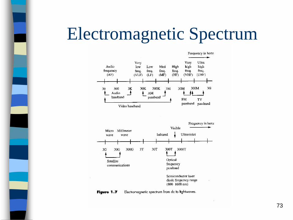
Optical Bandwidth
Figure 1.7 shows that lightwaves are
five to six decades higher than
microwaves in frequency
Each decade is 10 times higher in
frequency, which is the fundamental
reason for a large transmission
capacity in optical communications –
several THz or thousands of GHz
crciimsoc040101 73
Electromagnetic Spectrum

crciimsoc040101 74
Analogue versus Digital
An important characteristic in communications is the discreteness of a message that is transmitted
A digitized image is transmitted in discrete binary bits – two levels – This is called digital communication
However, in the previous AM and FM examples, input signals have a continuous waveform, this is called analogue communication

crciimsoc040101 75
Analogue versus Digital
Because a digital signal only has a finite
number of discrete levels, digital
communication is in general more immune to
noise than analogue communication
For example, if noise in the channel is
relatively small compared to the distance
between two adjacent levels, original
messages can be recovered correctly in the
presence of noise

crciimsoc040101 76
Analogue versus Digital
However, in analogue communication, once noise is added to the transmitted signal, it cannot be easily removed
This noise effect can accumulate when several analogue transmission links are cascaded
Because of this noise effect many analogue communication systems have been converted to digital
Most voice transmissions in current telephone networks are now digital

crciimsoc040101 77
Amplitude-shift keying (ASK)
When the input to the AM modulator in equation 1 is not continuous but instead has a finite number of discrete values, we have the digital counterpart of amplitude modulation called amplitude-shift keying (ASK)
A four level ASK signal is illustrated in figure 1.8
It can be seen that it is a passband digital signal, although only one carrier cycle per bit interval is drawn for illustration

crciimsoc040101 78
Amplitude-Shift Keying (ASK)

crciimsoc040101 79
U-Interface of ISDN A baseband version of the four level
amplitude modulated signal is used in the U-interface of the integrated services digital networks (ISDN)
The U-interface is the user interface between the ISDN network and its subscribers
In this defined interface, the bit rate is 160kb/s, including 144kb/s for user data and 16 kb/s for framing and control
Because of the 4 levels, each symbol carries two information bits, hence the baud rate is 80 kilobauds per second

crciimsoc040101 80
Advantage of Digital
Communication In analogue communication, if the transmitted
signal power is 0.1 mW and the noise power in the channel is 1 microwatt, the SNR is 100
In binary digital transmission, a SNR of 100 can have a bit error detection probability lower than 10-22
This implies that on average there is fewer than one bit in error if we transmit 1022 bits
Therefore the ratio of the number of correct transmitted bits to that of the error bits is 1022, much higher than the SNR of 100

crciimsoc040101 81
Trade off
The trade-off for better transmission quality in
digital communication is a larger transmission
bandwidth
For example, a 3kHz voice signal sampled at
an 8kHz rate and quantized at 8 bits per
sample requires a 64 kHz bandwidth in digital
transmission, and 6MHz video can require
45 MHz with moderate compression

crciimsoc040101 82
Coherent versus Incoherent
Detection
When a transmitted signal is received,
we need to detect what was originally
transmitted
If the signal is passband, it must be
shifted back to the baseband
There are two different ways to do this:
coherent or incoherent detection

crciimsoc040101 83
Coherent versus Incoherent
Detection
In coherent detection, a different carrier source at the receiver side is used to demodulate the received signal or to shift the passband signal back to the baseband
This carrier is generally called the local carrier and is synchronised to the received signal in frequency and phase
In incoherent detection, there is no use of the local carrier. Instead some nonlinear processing is used to extract the amplitude or envelope of the passband signal

crciimsoc040101 84
Coherent Detection
In AM transmission, let the transmitted signal be of the form given in equation (1).
If we can recover the same carrier, wc, at the receiver, we can simply recover the original message signal by multiplying the received signal by the same carrier and passing the product through a low pass filter
….1
crciimsoc040101 85
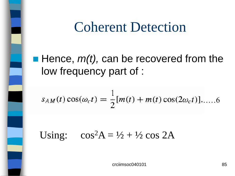
Coherent Detection
Hence, m(t), can be recovered from the
low frequency part of :
Using: cos2A = ½ + ½ cos 2A
………6

crciimsoc040101 86
Incoherent Detection
For an AM signal, where kAM is the modulation index such that IkAM m(t)I is always smaller than 1
By taking the square of this AM signal, we
have:
…….7
………..8

crciimsoc040101 87
Incoherent Detection
The first term is the desirable signal with a
proportional constant kAM.The second term is
the dc term and is not important. The third
term can be neglected if kAM is small enough.
The last term is a high frequency term and
can be eliminated by low-pass filtering
This is called envelope detection and is
incoherent because no local carrier is used
………….8

crciimsoc040101 88
Coherent versus Incoherent
Detection The primary trade-off between coherent and
incoherent detection is implementation complexity versus detection performance
Coherent detection requires a local carrier and associated carrier recovery; furthermore, the carrier source must be single frequency
In incoherent detection we suffer distortion and limited signal power (small kAM) in exchange for detection simplicity
In optical communications, most systems use incoherent detection for implementation simplicity at high speeds

crciimsoc040101 89
Photon Counting
In on-off-keying (OOK) optical
communications, the light source in the
transmitter is turned on if the input binary bit
is “1” and turned off if it is “0”
At the receiver, we can simply use a
photodiode that converts received photons
into photocurrent
With this scheme a local optical carrier is
unnecessary

crciimsoc040101 90
Quantum Limit
The quantum limit is the theoretical lower limit on the average signal energy needed to achieve a specified bit error rate (BER) in digital communication
For example, the quantum limit is 10 photons per bit to get a BER of 10-9 , in practice we need a few hundred photons
If coherent detection is used, the required number of photons can be much closer to the quantum limit
crciimsoc040101 91
Modulation and Line Coding
Similar to modulation that converts a baseband signal to a passband signal, line coding converts a binary input sequence into a suitable waveform for transmission. Because of similar functions line codes are also called modulation codes
In general modulation can be used in both digital and analogue communications
Line coding maps a finite set of signals to another set of signals with certain properties such as dc balance or frequent transitions

crciimsoc040101 92
Communication System
Compression
Error Control
Transmission
Line
Conditioning

crciimsoc040101 93
Modulation and Line Coding Line coding is always used in digital
communications, whether baseband or passband
In addition to modulating the amplitude or frequency of a carrier, we can modulate the phase of the carrier
A phase modulation (PM) signal has the following general form:
……..9

crciimsoc040101 94
Modulation Schemes
Where wc is the central carrier frequency, kPM
is the PM modulation index and m(t) is the modulation signal or information
If the baseband signal in equations (1), (7) and (9) is discrete and has M different levels, ±1, ±2, ±3, ±(M-1)
We have the corresponding different counterparts called M-level ASK (amplitude shift keying), FSK (frequency shift keying), and PSK (phase shift keying)
…………9

crciimsoc040101 95
RZ and NRZ Line Codes
Two of the simplest and most common line codes are the return-to-zero (RZ) and non-return-to-zero (NRZ) codes
These two codes are illustrated in figure (1.9)
These two codes transform binary bits, 1’s and 0’s, into pulses of different durations
RZ is better than NRZ from the time recovery consideration
For instance if there is a long sequence of 1’s,the transmitted NRZ signal is constant. This constant signal makes it difficult for the receiver to detect how many bits are transmitted

crciimsoc040101 96
Return-to-Zero & Non-return-to-
zero Line Codes

crciimsoc040101 97
RZ and NRZ Line Codes
If RZ is used, the transmitted signal is a
periodic pulse train.
The period equals the bit interval, therefore, it
easy for the receiver to detect the transmitted
bits
RZ signaling can be considered a special
case of amplitude modulation where the
carrier frequency is set equal to the bit rate

crciimsoc040101 98
Return-to-Zero & Non-return-to-
zero Line Codes

crciimsoc040101 99
Advantages of Optical
Communications
Large transmission capacity: the signals are
carried by high frequency carriers and WDM
is used. Capacity is several thousand GHz
Low loss: fibre attenuation can be as low as
0.2dB/km at a wavelength of 1.55 microns. If
only loss is considered, optical fibres can
transmit signals 5 times further than
waveguides and 50 times further than
twisted-pair wires
crciimsoc040101 100
Advantages of Optical
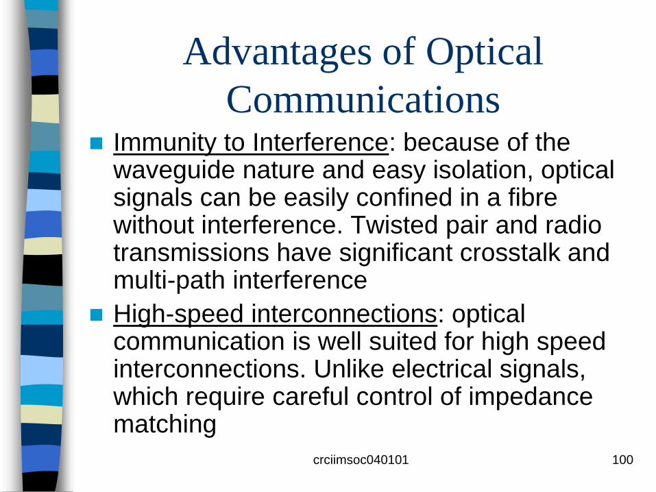
Communications Immunity to Interference: because of the
waveguide nature and easy isolation, optical signals can be easily confined in a fibre without interference. Twisted pair and radio transmissions have significant crosstalk and multi-path interference
High-speed interconnections: optical communication is well suited for high speed interconnections. Unlike electrical signals, which require careful control of impedance matching

crciimsoc040101 101
Advantages of Optical
Communications
Parallel transmission: because optical
signals can be transmitted in free
space, parallel transmission in three
dimensions is possible. This provides
powerful ways to interconnect large
numbers of processors for parallel
processing, photonic switching and
optical computing
crciimsoc040101 102
Components in Optical Comms
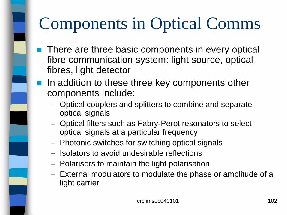
There are three basic components in every optical fibre communication system: light source, optical fibres, light detector
In addition to these three key components other components include: – Optical couplers and splitters to combine and separate
optical signals
– Optical filters such as Fabry-Perot resonators to select optical signals at a particular frequency
– Photonic switches for switching optical signals
– Isolators to avoid undesirable reflections
– Polarisers to maintain the light polarisation
– External modulators to modulate the phase or amplitude of a light carrier

crciimsoc040101 103
Components in Optical Comms
Figure 1.10 illustrates the use of these components in a photonic WDM switching network
Each laser diode in the transmitter is operated at a different carrier frequency
They are combined via an optical coupler
The combined signal is sent to splitter by an optical fibre
The splitter directs the received signal to each of the optical filters
Each filter is a passband filter at a selected optical frequency

crciimsoc040101 104
Optical Communication
Components

crciimsoc040101 105
Components in Optical Comms
Therefore, each signal on the transmitted
side can be routed to any detector on the
receiving side
Therefore this system performs photonic
switching
The received signal is coherently detected at
the receiver where a polariser aligns the
polarisation between the received signal and
the local oscillator signal

crciimsoc040101 106
Optical Communication
Components
crciimsoc040101 107
Advances in Optical Comms and
System Applications
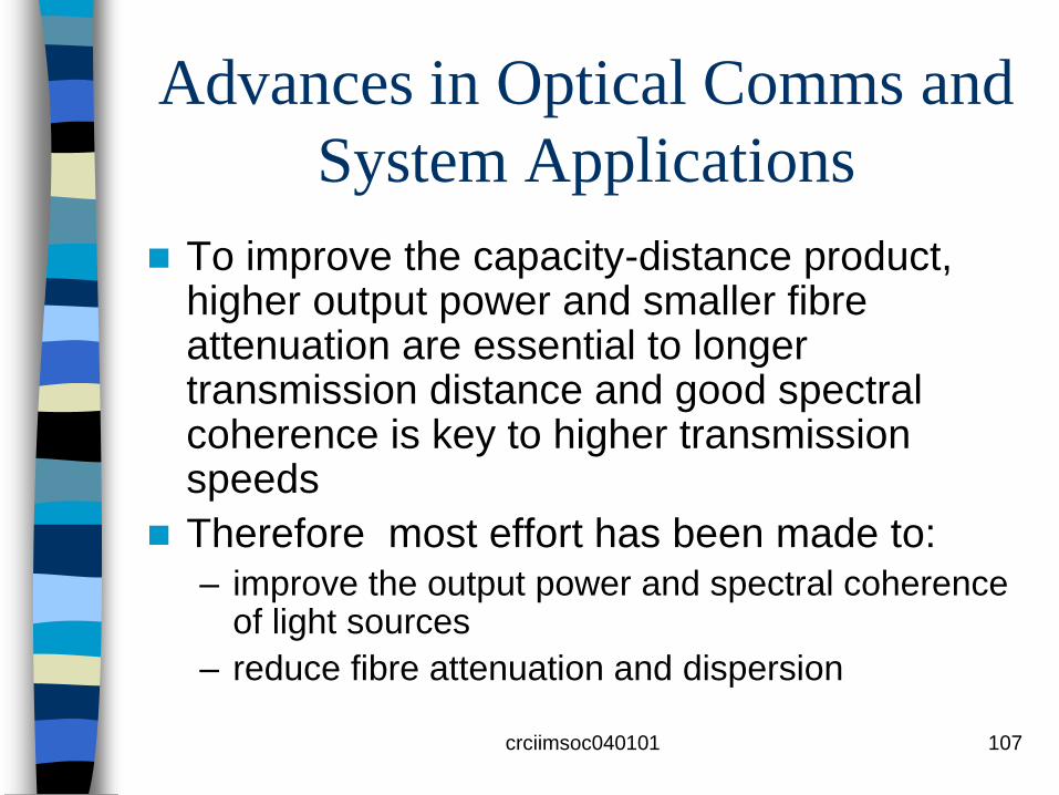
To improve the capacity-distance product, higher output power and smaller fibre attenuation are essential to longer transmission distance and good spectral coherence is key to higher transmission speeds
Therefore most effort has been made to: – improve the output power and spectral coherence
of light sources
– reduce fibre attenuation and dispersion

crciimsoc040101 108
Technological Advances

crciimsoc040101 109
Light Source Coherence
Power spectral density (PSD)
Problems to be avoided

crciimsoc040101 112
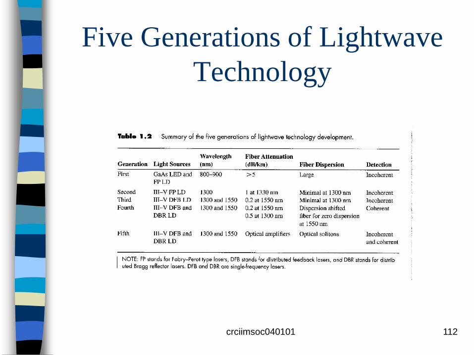
Five Generations of Lightwave
Technology
crciimsoc040101 113
First Generation
In the first generation, multimode fibres (MMF) and direct bandgap GaAs semiconductors were used.
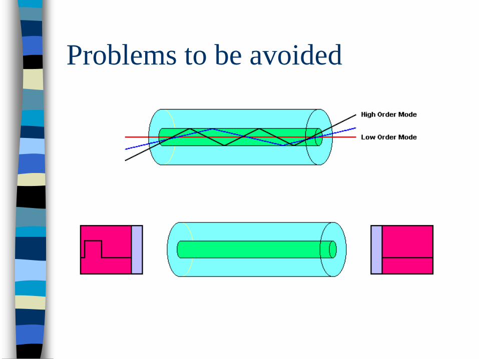
Multimode fibres allow multiple propagation modes that result in large modal dispersion
GaAs devices operate at the 800-900nm wavelength range in which fibres do not have the lowest attenuation ( > 5dB/km) or dispersion
Therefore , both transmission distance and speed were limited in the first generation

crciimsoc040101 114
Second Generation As fibre and material technology advanced, single
mode fibres (SMF) and other III-V compound semiconductors were used in the second generation
Single mode fibres have much smaller dispersion because there is no modal dispersion due to multiple propagation modes
III-V compounds such as InGaAsP (Indium Gallium Arsenide Phosphide) operated at a wavelength of 1300nm. At this wavelength, fibre attenuation is approximately 0.4-0.6 dB/km and fibre dispersion is essentially zero if higher order contributions are ignored
Transmission distance and speed are essentially limited by attenuation

crciimsoc040101 115
Third Generation
In the third generation, further improvement in semiconductor lasers made it possible to generate single longitudinal mode light signals at wavelengths of 1300 and 1500 nm
The coherence of the output light is much improved because of the single-mode output
At 1550 nm, the minimum attenuation of 0.2 dB/km can also be achieved
However, the dispersion is larger than at 1300 nm
To minimise dispersion and attenuation, dispersion-shifted fibres have been used for transmission at 1550 nm
crciimsoc040101 116
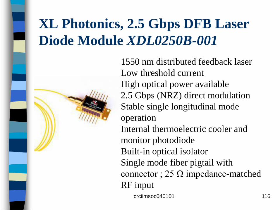
XL Photonics, 2.5 Gbps DFB Laser
Diode Module XDL0250B-001
1550 nm distributed feedback laser
Low threshold current
High optical power available
2.5 Gbps (NRZ) direct modulation
Stable single longitudinal mode
operation
Internal thermoelectric cooler and
monitor photodiode
Built-in optical isolator
Single mode fiber pigtail with
connector ; 25 Ω impedance-matched
RF input

crciimsoc040101 117
Fourth Generation In the first three generations, signals were detected
incoherently
In the fourth generation, coherent detection was used to enhance the receiver’s sensitivity
With coherent detection, received signals are amplified by the local carrier, which makes the system performance limited by shot noise
When coherent detection is used systems can achieve a detection performance of 50 photons per bit
Using a single frequency source, the distance limit is 210 km, and the capacity-distance product is 2100 Gb/s-km

crciimsoc040101 118
Fifth Generation To eliminate the attenuation and dispersion limits,
optical amplifiers and optical fibre solitons have been developed
Optical amplifiers amplify optical signals directly in the optical domain and are capable of simultaneously amplifying multiple signal wavelengths and this has facilitated Dense Wavelength Division Multiplexing (DWDM)
Optical amplifiers are used at the end of each fibre span to boost the power of the DWDM signal channels to compensate for fibre attenuation in the span

crciimsoc040101 119
Fifth Generation
Erbium-doped fibre amplifiers (EDFA) designed to operate with high inversion provide gain over a spectral range about 30 nm in width, from about 1530 nm to about 1560 nm
This spectral range can support roughly 40 DWDM signal channels with a separation of 100 GHz and 80 channels with a separation of 50 GHz, corresponding to 400 or 800 Gb/s, respectively, 10Gb/s OC-192 or STM-64 channels
In the future, with 40-Gb/s channels, capacities of 1.6 Tb/s (1600Gb/s) for 100-GHz spaced channels will be possible

crciimsoc040101 120
Telecom Windows
The first window at 800–900 nm was originally used. GaAs/AlGaAs-based laser diodes and light-emitting diodes (LEDs) served as transmitters, and silicon photodiodes were suitable for the receivers.
However, the fiber losses are relatively high in this region, and fiber amplifiers are not well developed for this spectral region. Therefore, the first telecom window is suitable only for short-distance transmission.

The second telecom window utilizes wavelengths
around 1.3 μm, where the loss of silica fibers is much
lower and the fibers' chromatic dispersion is very
weak, so that dispersive broadening is minimized.
This window was originally used for long-haul
transmission.
However, fiber amplifiers for 1.3 μm (based on, e.g.
on praseodymium-doped glass) are not as good as
their 1.5-μm counterparts based on erbium, and zero
dispersion is not necessarily ideal for long-haul
transmission, as it can increase the effect of optical
nonlinearities. crciimsoc040101 121
Telecom Windows

crciimsoc040101 122
Telecom Windows
The third telecom window, which is now very widely used, utilizes wavelengths around 1.5 μm.
The losses of silica fibers are lowest in this region, and erbium-doped fiber amplifiers are available which offer very high performance.
Fiber dispersion is usually anomalous but can be tailored with great flexibility (→ dispersion-shifted fibers).
crciimsoc040101 123
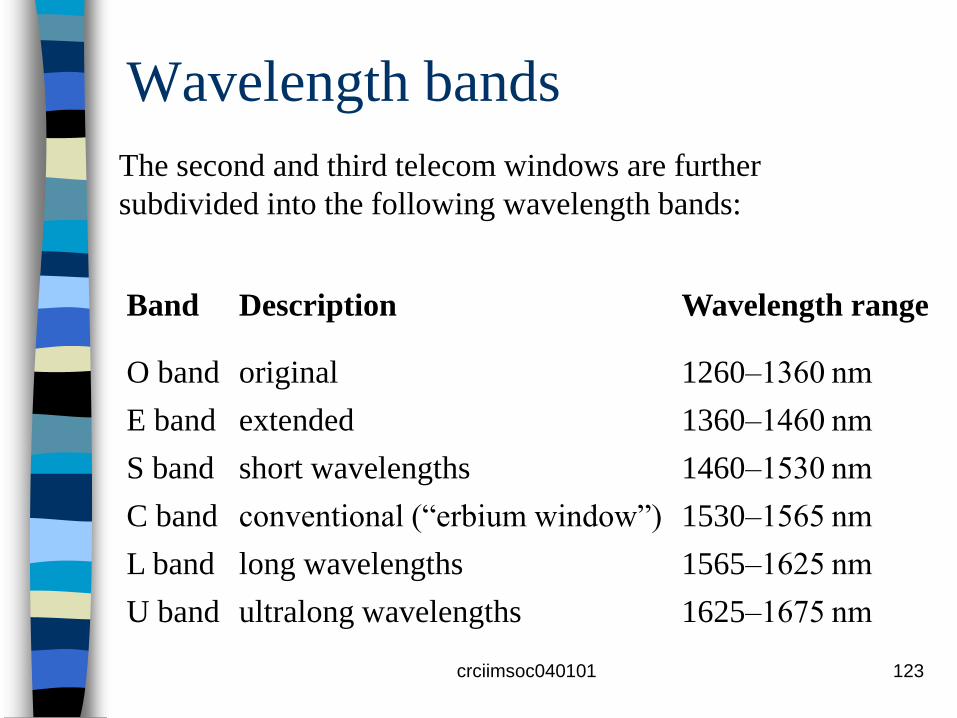
Wavelength bands
Band Description Wavelength range
O band original 1260–1360 nm
E band extended 1360–1460 nm
S band short wavelengths 1460–1530 nm
C band conventional (“erbium window”) 1530–1565 nm
L band long wavelengths 1565–1625 nm
U band ultralong wavelengths 1625–1675 nm
The second and third telecom windows are further
subdivided into the following wavelength bands:
crciimsoc040101 124
Wavelength bands
The second and third telecom windows
were originally separated by a
pronounced loss peak around 1.4 μm,
but they can effectively be joined with
advanced fibers with low OH content
which do not exhibit this peak.

crciimsoc040101 125
WDM Optical Fiber Amplifier – C band
LiComm WOFA designed for use
in high-performance and wide
bandwidth DWDM systems of core
network and Metropolitan network.
It offers high saturated output
power, wide flat range, high gain,
low noise figure, and automatic
gain control (AGC).

crciimsoc040101 126
Spectrum of input signals
Spectrum of amplified signals

crciimsoc040101 127
Characteristic of gain & noise figure+23dBm Pout (Pin=-1dBm )
30
25
20
15
105 Gain
NF01525 1530 1535 1540 1545 1550 1555 1560 1565 1570
Wavelength [nm]
crciimsoc040101 128
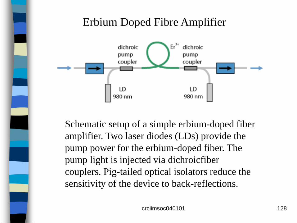
Schematic setup of a simple erbium-doped fiber
amplifier. Two laser diodes (LDs) provide the
pump power for the erbium-doped fiber. The
pump light is injected via dichroicfiber
couplers. Pig-tailed optical isolators reduce the
sensitivity of the device to back-reflections.
Erbium Doped Fibre Amplifier

crciimsoc040101 129
Erbium Doped Fibre Amplifier

Pumping at 980nm and 1450 nm is effective
In order to pump carriers from the ground level to the
metastable level a pumping source at wavelength
1450nm, 980nm, or 800nm can be used
These will excite the carriers to 4I13/2 , 4I11/2 or 4I9/2 ,
respectively. Due to their short lifetime excited
carriers at 4I11/2 or 4I9/2 will quickly move down to the
metastable level 4I13/2 .
The difficulty of finding good laser sources limits
pumping to 800, 980, and 1470 nm.
crciimsoc040101 130

crciimsoc040101 131
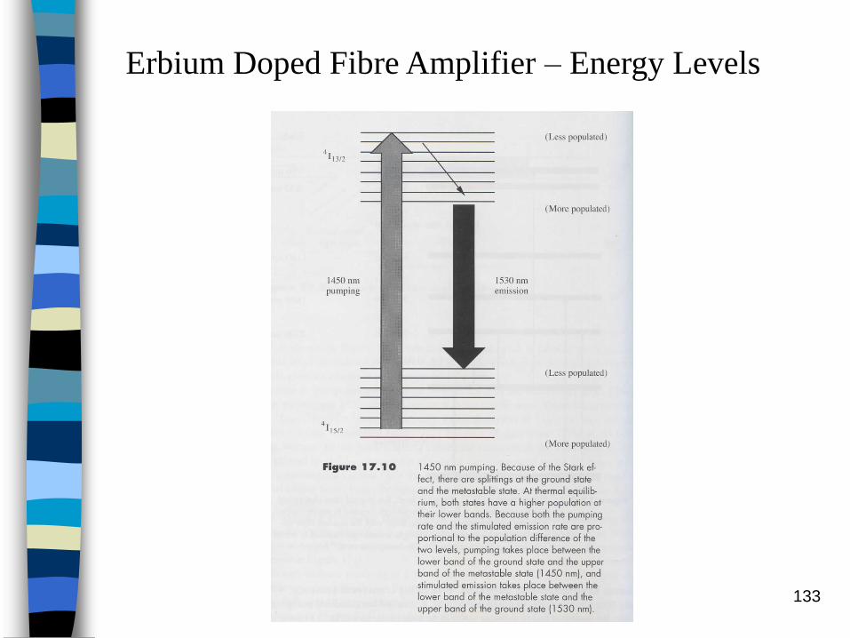
Erbium Doped Fibre Amplifier – Energy Levels
Emission wavelength 1530 nm

Pumping at 800nm is not effective
Because of the excited absorption (ESA) from 4I13/2 to2H11/2 pumping at 800 nm is not effective
Therefore, only 980nm and 1470nm pumpings are
used practically
1470nm sources are generally available
980nm has a higher pumping efficiency (around
10dB/mW) compared to 6dB/mW at 1470nm
980nm has lower pumping noise, so it is preferred.
crciimsoc040101 132
crciimsoc040101 133
Erbium Doped Fibre Amplifier – Energy Levels

crciimsoc040101 134
Absorption and Emission Cross Sections
crciimsoc040101 135
Absorption and Emission Cross Sections

crciimsoc040101 136
Absorption Spectrum of Erbium

crciimsoc040101 137
Erbium Doped Fibre Amplifier – Pumping

crciimsoc040101 138

crciimsoc040101 139

crciimsoc040101 140

crciimsoc040101 141

crciimsoc040101 142
Absorption and Emission Cross Sections

crciimsoc040101 143
Stimulated Emission

crciimsoc040101 144
Carrier Rate Equation

crciimsoc040101 145
Upper Limit of Gain

crciimsoc040101 146

crciimsoc040101 147

crciimsoc040101 148

Optimum EDFA length
crciimsoc040101 149

crciimsoc040101 150

crciimsoc040101 151
Network Innovation Laboratories-NTT
NTT succeeded in the
Dispersion Managed
soliton transmission of
40 Gbit/s - 1020 km and
20 Gbit/s - 2040 km
using the optical fiber
cable installed between
Mito and Maebashi (170
km)

crciimsoc040101 152
Summary
A communication network consists of interconnected links, each of which has three basic elements: transmitter, channel, receiver
A communication system is a point-to-point transmission link that can be implemented by:– Baseband or passband transmission
– Digital or analogue modulation
– Coherent or incoherent detection
All optical communication systems are passband at visible or infrared frequencies. They can be digital or analogue, coherent or incoherent

crciimsoc040101 153
Summary Line coding and modulation are used to convert input
signals into forms suitable for transmission. Line coding is used for digital transmission and modulation is used for passband communications
Advantages of optical fibre communication include:– Large transmission capacity
– Low attenuation
– Interference immunity
– High speed interconnection capability
– Parallel transmission
The focus of lightwave technology development is to increase transmission distance and capacity. Low loss fibres and single-mode light sources are the keys to accomplishing these objectives

End
crciimsoc040101 154