FIBRE CHANNEL - Springer · PDF fileAbstract 5 FIBRE CHANNEL Martin W. Sachs IBM Research T....
21
Abstract 5 FIBRE CHANNEL Martin W. Sachs IBM Research T. 1. Watson Research Center P. O. B. 704 Yorktown Heights, NY 10598 Fibre Channel is being developed as an industry-standard transmission medium, interconnection network, and logical protocol to support both traditional I/O and communications in a local area. It will support a spectrum of applications requiring either high bandwidth, low cost, or both. Mappings are being developed to support several industry standard upper level protocols. Introduction Accredited Standards Committee X3's task group X3T9.3 is developing Fibre Channel (FC)[l], a standard for a serial lIO channel, to provide a transport vehicle for present and future standard upper level protocols. Upper level protocols of immediate interest to X3T9.3 are the Intelligent Peripheral Interface Device Generic Command Set (IPI3) [2], Small Computer System Interface (SCSI)[3], High Performance Parallel Interface Framing Protocol (HIPPI-FP) [4, 5], Internet Protocol (IP)[6], and command sets equivalent to that of International Business Machines Corp. System/390® lIO[7, 8]. In each case, the logical protocol, rather than the physical interface protocol, is being mapped to FC. As its name indicates, the primary focus of FC is on optical fiber interconnection. However, the physical layer definition includes copper coaxial and shielded twisted pair interconnections for low cost. short distance interconnection. The standard includes bandwidths ranging from 12.5 to 100 megabytes per sec (MB/s). A. N. Tantawy (ed.), High Performance Networks © Kluwer Academic Publishers 1994
-
Upload
vuongtuong -
Category
Documents
-
view
217 -
download
2
Transcript of FIBRE CHANNEL - Springer · PDF fileAbstract 5 FIBRE CHANNEL Martin W. Sachs IBM Research T....

Abstract
5 FIBRE CHANNEL
Martin W. Sachs IBM Research
T. 1. Watson Research Center P. O. B. 704
Yorktown Heights, NY 10598
Fibre Channel is being developed as an industry-standard transmission medium, interconnection network, and logical protocol to support both traditional I/O and communications in a local area. It will support a spectrum of applications requiring either high bandwidth, low cost, or both. Mappings are being developed to support several industry standard upper level protocols.
Introduction Accredited Standards Committee X3's task group X3T9.3 is developing Fibre Channel (FC)[l], a standard for a serial lIO channel, to provide a transport vehicle for present and future standard upper level protocols. Upper level protocols of immediate interest to X3T9.3 are the Intelligent Peripheral Interface Device Generic Command Set (IPI3) [2], Small Computer System Interface (SCSI)[3], High Performance Parallel Interface Framing Protocol (HIPPI-FP) [4, 5], Internet Protocol (IP)[6], and command sets equivalent to that of International Business Machines Corp. System/390® lIO[7, 8]. In each case, the logical protocol, rather than the physical interface protocol, is being mapped to FC.
As its name indicates, the primary focus of FC is on optical fiber interconnection. However, the physical layer definition includes copper coaxial and shielded twisted pair interconnections for low cost. short distance interconnection. The standard includes bandwidths ranging from 12.5 to 100 megabytes per sec (MB/s).
A. N. Tantawy (ed.), High Performance Networks
© Kluwer Academic Publishers 1994

110 High Performance Networks
Unrepeatered distances up to 10 km are specified, with the maximum depending on other physical parameters.
FC is intended to support both classical I/O channel applications (e.g. SCSI and IPI3) and local area communications applications (IP). HIPPI framing protocol applications are in both categories. The design point of the logical protocols is for distances of the order of a few kilometers, for interconnection within a building or establishment campus. In addition, care is being taken that FC should efficiently support gateways to wide area networks.
In general, proposed applications of FC include both high bandwidth and low cost applications. Examples of high bandwidth applications include attachment of visualization workstations to supercomputers and attachment of high performance disk arrays to both supercomputers and high performance workstations. An example of a low cost application is the interconnection of large numbers of low cost disk drives within a storage subsystem, in which FC with a serial copper transmission medium is expected to provide significant cost reduction compared to today's parallel bus interconnections.
Interconnection Topology The primary topological elements in FC are fabric, nodes, and N_Ports. The topology is illustrated in Figure 1.
Fabric is the term used in FC to denote the medium which interconnects N_Ports. The initial emphasis of the FC Committee is on a fabric consisting of spacedivision switches for high-performance applications. Work is also in progress on fabrics, such as loops, which are more suited to low-cost interconnection. The standard also permits two N_Ports to be directly connected by a link, with no intervening fabric. A node is an element which contains executing applications and one or more connections to the fabric. In general, a node contains a single instance of an operating system although this is not specified by the standard.
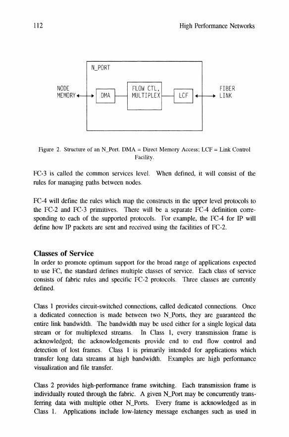
An N_Port (node port) is the embodiment of the function needed at a node to connect the node to a fabric. The standard does not specify which FC functions are to be implemented in hardware and which are to be implemented in software. A typical N_Port can be expected to include a link control facility (e.g. serial transmitter and receiver) which connects to the serial link, a direct memory access connection to the main memory of the node, and that function, to be described subsequently, which controls the information flow on the link and between the

Fibre Channel 111
NODE
N_PORTI IN_PORT
NODE N_PORTt-- FABRIC --1N_PORT NODE
Figure 1. Fabric, Nodes, and N_Ports
link and the memory of a node. A node controls one or more N_Ports. An
N_Port is illustrated in Figure 2.
Functional Levels FC is divided into five functional levels, named FC-O through FC-4. Of these,
FC-O, FC-1 and FC-2 are included in the initial "Physical and Signaling Interface" (FC-PH) definition[1]. At this time of writing, work is beginning on the FC-3 and
FC-4 definitions. The functional levels are illustrated in Figure 3.
FC-O defmes the physical level. This includes permitted transmission media,
optical or electrical specifications of the media, connectors, bit rates, jitter specifi
cations, and unrepeatered distances.
FC-1 defines the encoding of data and control information on the serial link. It
also includes bit, byte, and word synchronization rules and certain error controls.
FC-2 defines the signalling protocol and is roughly equivalent to a data link
control (DLC) layer in a standard communications protocol. However, with a
fabric present, the logical link control (LLC) function within the DLC operates
end to end, between two communicating N_Ports, rather than separately on each
link.
112
NODE MEMORY
FLOW CTL. MUL TIPLEX
High Performance Networks
FIBER +-l---+ LINK
Figure 2. Structure of an N]ort. DMA = Direct Memory Access; LCF = Link Control Facility.
FC-3 is called the common services level. When defined, it will consist of the
rules for managing paths between nodes.
FC-4 will define the rules which map the constructs in the upper level protocols to the FC-2 and FC-3 primitives. There will be a separate FC-4 definition corresponding to each of the supported protocols. For example, the FC-4 for IP will define how IP packets are sent and received using the facilities of FC-2.
Classes of Service In order to promote optimum support for the broad range of applications expected to use FC, the standard defines multiple classes of service. Each class of service consists of fabric rules and specific FC-2 protocols. Three classes are currently defined.
Class 1 provides circuit-switched connections, called dedicated connections. Once a dedicated connection is made between two N_Ports, they are guaranteed the
entire link bandwidth. The bandwidth may be used either for a single logical data stream or for multiplexed streams. In Class 1, every transmission frame is acknowledged; the acknowledgements provide end to end flow control and detection of lost frames. Class 1 is primarily intended for applications which transfer long data streams at high bandwidth. Examples are high performance visualization and file transfer.
Class 2 provides high-performance frame switching. Each transmission frame is individually routed through the fabric. A given N_Port may be concurrently transferring data with multiple other N_Ports. Every frame is acknowledged as in Class 1. Applications include low-latency message exchanges such as used in

Fibre Channel 113
UPPER LEVEL PROTOCOL
FC-4 MAPPING
FC-3 COMMON SERVICES
FC-2 LOGICAL SIGNALING
FC-l TRANSMISSION
FC-0 PHYSICAL
Figure 3. Fe level structure
remote procedure call, and record oriented disk accesses such as used with some
file server protocols and traditional disk I/O.
Class 3 provides high perfonnance frame switching but without acknowledge
ments. One application for Class 3 will be transmission of multicast advisory
messages, such as will be required for configuration management and fabric man
agement. In these applications, elimination of congestion due to acknowledgement traffic is more important than detecting, at the FC-2 level, the occasional loss of a message due to the essentially unreliable nature of Class-3 transmission. When
needed, application-level responses will provide confinnation of message delivery. Another potential use of Class 3 is for efficient communication to a router or
gateway to a wide area network where the transport layer provides the end to end flow control and error management which Class 3 lacks.
It is likely that future enhancements of FC will include one or more additional
classes of service which support newly emerging applications.
FC-O, Physical Characteristics FC-O defines the menu of choices for the physical parameters of the link. Support
of the large variety of FC applications requires a wide range of cost and perfonn
ance options. The large number of options is a cause of concern with regard to interoperability; it may be expected that market forces will eventually limit the set
of choices which will be in widespread use, especially as the higher perfonnance technologies mature and their costs are lowered.

114 High Perfonnance Networks
Listing all of the pennissible combinations of technology parameters is beyond the
scope of this article. Reference should be made to the FC-PH specification[l]. Following are the options for the key parameters of the standard:
• Transmission media: optical fiber, copper coaxial, copper shielded twisted pair
• Transmission rates: 1062.5, 531.25, 265.625, and 131.8125 Mbaud.
• Optical cables
- Single mode: 9 pm
- Multimode: 50 pm and 62.5 pm
• Optical wavelength
- Single-mode: 1300 nm - Multimode: 780 nm
• Optical emitters: Light-emitting diode, laser
• Maximum distances (depending on other options)
- Optical: 500 m - 10 km - Electrical: 10-100 m
• Optical connector: SC connector
Fe-I, Transmission Protocol The transmission code is an adaptive 8B-10B code with limited run length[9]. The coding rules enable a receiver to detect all odd-bit errors and a large number of other error patterns as code violations. In addition to the encoding of the 256 8-bit data characters, the code defines a number of additional characters which may be used for control functions. Several have unique "comma" properties.
These characters cannot appear in an error-free data stream as a result of the juxtaposition of two data characters. The comma characters can therefore be used to enable a receiver to synchronize itself to the character boundaries in the data stream.
FC-1 defines the transmission fonnat as a series of 4-byte words (40 bits after encoding). It also dermes a number of control words, called ordered sets, which are used as frame delimiters, idle words, and for other purposes. Each ordered set consists of a particular comma character (the character tenned K28.5) followed by three data characters which identify the particular ordered set and are chosen to provide a high degree of error immunity. To enable a receiver to maintain syn-

Fibre Channel 115
chronization to the word boundaries, a stream of idle words is transmitted between frames.
In addition, FC-l defines the rules by which a receiver determines when it is synchronized to character and word boundaries, when it is not synchronized, and how it reacquires synchronization. The rules are based on frequency of detection of code violations. They provide synchronization stability by avoiding unnecessary resynchronization when an isolated bit error occurs.
FC·2, Logical Signalling Protocol FC-2 defines the logical signalling protocol. It is roughly equivalent to the LLC layer of a standard communications protocol. Areas of protocol defined by FC-2 include transmission frame format, N-Port addressing, service classes, flow control, multiplexing management, initialization, and error detection.
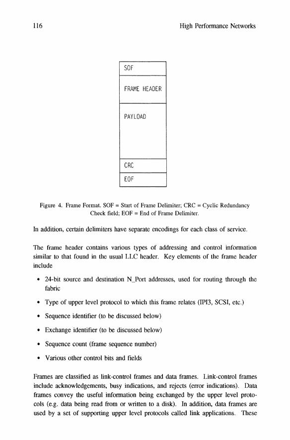
Franne Structure All information except certain primitive controls, to be discussed, is transferred in frames. The frame format is illustrated in Figure 4. Each frame is bounded by a start of frame delimiter and end of frame delimiter. The contents of the frame consist of frame header, data field, and 4-byte cyclic redundancy check word (CRC).
In addition to bounding the frame, the delimiters are used for certain control functions where the required function must be rapidly identified without requiring decoding into the 8-bit domain or checking the frame CRC. Each type of delimiter consists of one ordered set. The data characters in the ordered set encode the requested control function. Following are the control functions performed by the delimiters:
• Start of frame
- Request CIass-l circuit connection - Indicate first or only frame of sequence of frames (to be discussed below) - Indicate second through last frame of sequence
• End of frame
- Break CIass-l circuit connection - Indicate last or only frame of a sequence - Indicate first through next-to-Iast frame of a sequence - Abort frame (disregard contents)
116 High Performance Networks
SOF
FRAME HEADER
PAYLOAD
CRC
EOF
Figure 4. Frame Format. SOF = Start of Frame Delimiter; CRC = Cyclic Redundancy Check field; EOF = End of Frame Delimiter.
In addition, certain delimiters have separate encodings for each class of service.
The frame header contains various types of addressing and control information similar to that found in the usual LLC header. Key elements of the frame header include
• 24-bit source and destination N_Port addresses, used for routing through the fabric
• Type of upper level protocol to which this frame relates (IPI3, SCSI, etc.)
• Sequence identifier (to be discussed below)
• Exchange identifier (to be discussed below)
• Sequence count (frame sequence number)
• Various other control bits and fields
Frames are classified as link-control frames and data frames. Link-control frames include acknowledgements, busy indications, and rejects (error indications). Data frames convey the useful information being excbanged by the upper level protocols (e.g. data being read from or written to a disk). In addition, data frames are used by a set of supporting upper level protocols called link applications. These

Fibre Channel 117
provide various initialization, management, and recovery functions which are performed using basic FC-2 constructs.
The data field contains the useful information, or payload, being conveyed by the frame. In addition, the data field may contain one or more optional headers required by the particular upper level protocol to which the payload belongs. The maximum size of the data field, including any optional headers, is 2112 bytes. This is a somewhat arbitrary figure which was chosen based on trade-offs among factors such as transmission efficiency, CRC coverage, expected costs of transmission, and receiver buffering at the highest bandwidth, etc.
Primitive Sequences A primitive sequence is the continuous repetition of a particular ordered set. Continuous sequences are defined for signalling under conditions in which the use of frames is either unreliable or inappropriate. Use of frames is unreliable under conditions of high link error rate. Frames are inappropriate, for example, if it is likely that the receiver is not synchronized to character and word boundaries, such as during link initialization.
Reliable receipt and decoding of a primitive sequence under high link error rate is assured by the continuous repetition, combined with the redundancy in the combination of data characters used for each ordered set. Depending on the protocol, a continuous sequence is transmitted either for a fixed length of time or until a specified primitive sequence is received in response.
The following primitive sequences are defined by FC:
Not Operational Sequence (NOS): An N_Port or port on a switch sends NOS if it is unable to detect a proper received signal or to acquire character and word synchronization. It informs the port at the other end of the link that a transmission or reception problem exists.
Offline Sequence (OLS): An N_Port or port on a switch sends OLS to signal that it is about to go off line or power down. OLS is thus an indication to the port at the other end of the link that detected errors should be ignored.
Link Reset (LR) and Link Reset Response (LRR): LR and LRR are used in interlocked fashion to cause the fabric to remove a dedicated connection, if one exists, when the state of the connection is unknown.

118 High Performance Networks
Information Units, Multiplexing, and How Control The main function of FC-2 is to deliver an information unit from the sending instance of an upper level protocol in one node to the receiving instance of the same upper level protocol in a different node. The content and length of the information unit are determined by the upper level protocol; the length of a single information unit is essentially unbounded, or may be limited to 232 bytes, depending on other parameters. For all practical purposes, then, an information unit may be any length defmed by the upper level protocols and a data stream may consist of a single information unit or a flow of information units. Information units may be delivered in any of the three classes of service, as determined by system performance and implementation requirements.
An information unit is transmitted from the sending to the receiving N_Port as the payload of a flow of frames, which will be described below. FC-2 is responsible for flow control and error detection within the flow of frames and for correct reassembly of the information unit at the receiving N]ort. The definition of FC-2 permits a fabric to misorder frames in a class 2 and class 3; the FC-2 function at the receiving N_Port can correctly reassemble an information unit in spite of misordered delivery by the fabric. In general, FC-2 will also preserve order of delivery of information units within a single stream, provided that the upper level protocol obeys certain non-mandatory rules.
It will be noted that if FC-2 is viewed as the medium access control (MAC) layer of a communications protocol stack, it differs from conventional MAC layers, such as those in the IEEE 802 protocol suite[10] or FDDI[ll], in its treatment of the information unit. In conventional MAC protocols, the maximum transmission unit must fit in one physical frame and reassembly of longer streams of information is the responsibility of the LLC or transport layer. In order to further its goal of high transmission bandwidth, FC places segmentation and reassembly of longer data streams in FC-2, where it can be implemented in high speed N_Port function. In this regard, FC is similar to IBM's ESCON VO Interface[8] in which segmentation and reassembly are performed by the ESCON interface (channel) function.
FC-2 defines function which permits multiple independent streams of data to be multiplexed by interleaving frames belonging to the different streams. In class I, multiple streams may concurrently be transferred in both directions between two N_Ports over a dedicated connection. In class 2 and Class 3, a given N_Port may also be communicating through the fabric with multiple other N_Ports. Two constructs are provided for managing multiplexing; they are called the sequence and the exchange. An implementation may make use of one or both for multiplexing management.

Fibre Channel 119
A sequence is a series of consecutive frames within an exchange (to be explained below) which are denoted by the same value of a sequence identifier in the frame header. An infonnation unit is transferred as the frame payload of one or more sequences. In the simplest case, an infonnation unit is transferred as a single sequence. Since the FC-2 definition in this area is subject to change, we will assume, for the purpose of this article, that an information unit is transferred as a single sequence.
An exchange is a relationship between instances of an upper level protocol in two nodes which is used to manage a unidirectional or bidirectional flow of related infonnation units. In the I/O applications of FC, an exchange is an abstraction representing a single I/O operation , such as the transfer of a block of data, or a chain of related I/O operations which may transfer a stream of blocks between a host node and an VO device controller node. Within FC-2, an exchange is said to connect an exchange originator with an exchange responder. The frame header of every frame associated with a given exchange is labelled by a pair of identifiers, one supplied by the originator (originator exchange identifier, OX_ID) and one supplied by the responder (responder exchange identifier, RX_ID). The combination of OX_ID and RX_ID uniquely identifies the exchange at each N_Port. Within each exchange, the flow of infonnation units, and their contents, is defined by the upper level protocol.
Using the exchange identifiers and sequence identifier, an N_Port is enabled to multiplex concurrent outbound streams of data and demultiplex inbound streams to the various receiving upper level processes.
The basic unit of end-to-end flow control and error detection in FC-2 is the sequence. The frames within a sequence have frame sequence numbers (known as sequence count in FC-2). Flow control, error detection, and reordering of misordered frames are based on the sequence count. The flow control algorithm is a variant of a conventional sliding window algorithm such as that in IEEE/ISO 8802.2[12]. In FC-2, the window size is statically allocated on a physical basis between the members of each pair of communicating N_Ports while the sequence counts are managed separately for each sequence. The window is referred to in FC-2 as credit. A N_Port is free to dynamically allocate credit among the concurrent exchanges. FC-2 perfonns error detection (e.g. detection of missing frames) but not error recovery, which is delegated to the upper levels.
There are two reasons for delegating error recovery to the upper levels. First, given the low transmission error rates expected in FC-based systems, this is an acceptable means of reducing N_Port complexity without significantly impacting

120 High Performance Networks
system performance. Second, in many of the foreseen applications, in particular the traditional JlO applications, the upper level protocol must make recovery decisions. For example, in many 1/0 implementations, data to be written to a device are cut through the N_Port directly to the device without waiting for the information unit (data block) to be fully buffered and checked. If a transmission error occurs, the upper level (i.e. host device driver and control unit device management function) must be involved in recovery since the partially written information unit may have to be overwritten during the retry. This is not a burden for the device management functions since generally, the same algorithms can be used for transmission error recovery as are used for device error recovery.
Node-Level Routing FC-2 includes a number of constructs which provide performance assistance in routing received information between the N_Ports and higher level processes in the nodes. These constructs are embodied in fields in the frame header and in an optional header called the association header.
A data-structure type (TYPE) field in the frame header identifies the upper level protocol of which the frame is a part. FC defines specific TYPE values for supported upper level protocols, such as IP, IPI3, SCSI, Fibre Channel Services, and others. The TYPE field may be used for routing to specific TYPE-dependent "hardware" in the N_Port, for routing to the appropriate software, or simply to verify that the receiving N_Port supports the identified protocol.
An information-category field in the frame header provides for routing data to specific buffers. For example, control and data messages can be routed to separate buffers based on the information category. Four information categories are defined: solicited control, unsolicited control, solicited data, and unsolicited data. The term "solicited" means that the sequence is expected as a result of earlier steps in an exchange. The term "unsolicited" means that the sequence is not expected, such as receipt of the first sequence of an exchange. Additional categories may be defined by specific FC-4s.
The association header provides process and operation tokens (called process associators and operation associators) which may be used to directly route information to entities in the node. The association header contains a process associator and operation associator supplied by the exchange originator and a similar pair supplied by the exchange responder. The associator values are exchanged at certain points in the exchange protocol. Typically, an operation associator contains an address or token representing the higher level control block for an 110 operation. A process associator may be used as a dispatching quantity

Fibre Channel 121
to notify a receiving process that data have arrived. FC-2 defines the protocol for exchanging the associator values; actual use of the associators is defined by the FC-4s and/or the node design. The associator header is also used as part of a protocol which enables an exchange to be started on one physical route (pair of N_Ports) and later continued on a different route between the same two nodes.
Fabric FC provides for a wide variety of fabric designs to meet different cost and performance requirements. As mentioned earlier, the initial emphasis is on networks of space-division switches for high performance. A concurrent activity is investigating topologies such as loops for low cost, relatively short-distance applications.
A fabric may consist of either a single switch, called a fabric element, or a network of interconnected fabric elements. A fabric element which supplies class-l service is generally expected to be non-blocking. However, a fabric consisting of multiple fabric elements may be blocking. Fabric design considerations are discussed in ref. [13] and [14]. Each N_Port is connected, via a single link, to a connection point on the fabric called an F _Port, as illustrated in Figure 5.
Fabrics provide one or both of two basic services: circuit switching and frame switching. In circuit switching, which provides class-l service, a physical fullduplex circuit (dedicated connection) is established between two N_Ports. The connected N_Ports can then exchange information at essentially the full bandwidth of the links which connect the N_Ports to the fabric. In frame switching, which provides class-2 and class-3 service, each frame is individl;ally routed through the fabric without creating an explicit circuit connection. A given fabric may support either or both of circuit switching and frame switching. Since a typical FC-based system is expected to support a variety of applications, it is likely that fabric vendors will supply both modes of operation in the same fabric. Ancor Communications, Inc. (Minnetonka, MN, U. S. A.) has announced a fabric which supports all three classes of service and can interconnect up to 4096 N_Ports.
Circuit Switching Dedicated connections are dynamically requested and removed by the communicating N_Ports. To request a connection to send one or more sequences, an N_Port places a specific start of frame delimiter, called "start of frame connect, class I" (SOFcl) on the frrst frame to be sent. This instructs the fabric to make a connection to the N_Port which is identified by the destination address in the frame and to send the frame to that destination. When the sending N_Port receives the acknowledgement to the connection request from the other N_Port, it

122 High Performance Networks
FE FE
Figure 5. N_Ports connected to a fabric. The figure shows two fabric elements (FE) interconnected by three links.
is assured that the connection exists and it can then continue transmitting the frames in the sequence. The standard does not specify a connection request latency; however, typical latencies are expected to be in the range of a few microseconds plus the end to end round trip delay. The Ancor fabric has a class-l internal connection latency of 5 to 50 J1s, depending on configuration.
To request removal of a dedicated connection, an N_Port places a specific end of frame delimiter, called "end of frame, disconnect-terminate" (EOFdt) on the acknowledgement to a data frame. The EOFdt delimiter causes the fabric to send the frame to its destination and than break the connection. FC-2 protocols enable the two communicating N_Ports to coordinate the disconnection process.
Transmission errors can cause the state of the connection to be unknown. For example, the acknowledgment which confirms the existence of the connection may be lost. To recover from this situation, the link-reset protocol provides for reliable return of the connection to a known disconnected state. To eliminate the possibility of ambiguity due to race conditions with unrelated connection requests, this protocol is performed with interlocked primitive sequences (link reset and link reset response).

Fibre Channel 123
A connection request may not be able to be satisfied either because the destination is already connected to a different N_Port or because of a blocking condition in the fabric. When this happens, the fabric returns a busy response to the requesting N_Port. The requesting N_Port may then re-try the request at a later time.
Control and management of dedicated connections through a multi-element fabric are not specified in the current version of the standard. This means that all the fabric elements in a multi-element fabric will, most likely, be supplied by the same vendor. The FC committee is now beginning discussions of interoperability among fabric elements supplied by different vendors.
Frame Switching Frame switching provides support for class-2 and class-3 service. From the viewpoint of the fabric, class 2 and class 3 are identical except that the fabric owes non-delivery notification in class 2 but not in class 3.
As mentioned above, frame switching routes each frame individually through the fabric. Frame switching is thus a particular case of packet switching. The fabric is permitted to allow the frames in a sequence to be misordered; restoration of ordering is the responsibility of the destination N_Port. Allowing misordering may permit the fabric to achieve improved throughput by sending any frame on any available route; however, such misordering may have adverse performance consequences at the recipient N_Port. Making the appropriate trade-offs between N_Port design and fabric design involves consideration of the architecture and design of the system in which an N_Port is embedded as well as the specifics of N_Port and fabric design. Such a design problem is significantly complicated by the open, multi-vendor environment of Fe.
Congestion in FC frame-switched fabrics is managed by a process called buffer-tobuffer flow control. This is a rudimentary sliding window flow control algorithm which is performed between each N_Port and the F _Port to which it is connected. Buffer-to-buffer flow control is performed on the physical frame flow, without reference to exchange and sequence identifiers. It uses a fixed window size (credit) which is specified during N_Port initialization, and does not use frame sequence numbers. With this type of algorithm, performance as a function of distance is directly affected by the number of receive buffers available at the N_Port and F _Port. In class 2, both end-to-end and buffer-to-buffer flow control take place simultaneously.
Fabrics which support both circuit and frame switching may also provide an operating mode called intermix. Intermix permits an N_Port to send and receive

124 High Perfonnance Networks
class-2 and class-3 frames while engaged in a dedicated connection. The class-2
and class-3 frames may be sent to or from any other N_Port attached to the fabric.
Intennix thus enables an N_Port to utilize bandwidth which it does not need in the
dedicated connection for other related or unrelated purposes.
Addressing All addressing through the fabric is end to end. Each N_Port is assigned a 3-byte
address, called an N_Port Identifier, which is supplied as the source or destination
address in each frame. N]ort identifiers may be either defined statically or
assigned to each N]ort by the fabric during N_Port initialization. Assignment by
the fabric enables the fabric to assign address values in a way which minimizes
the complexity of its routing tables. Assignment of address values by the fabric
also facilitates configuration flexibility and reconfiguration of a multi-element
fabric. One of the reasons for the large (24-bit) address is to pennit segmentation
of the address in a multi-element fabric in order to reduce the size of the routing
tables. For example, one part of the address might select a fabric element, while
the rest of the address selects a destination within that fabric element.
Because the fabric may dynamically assign N_Port identifiers, configurations cannot be defined in tenns of N_Port identifiers. Each node, and each N_Port has
a "pennanent" unique identifier, called a worldwide name. Worldwide names may be provided at the time of manufacture or otherwise assigned in some way which
makes them pennanent and unique. A name-server function, with a well-known N_Port address, provides translation from an N_Port's worldwide name to its
current N_Port ID, once that N_Port has completed initialization and made itself
known to the name server. In addition, each physical link can be identified, for
purposes such as problem reporting, by the worldwide names of the N]ort and
F _Port which the link interconnects. The standard provides that worldwide names
may be IEEE or CCnT names or locally administered. The type of name is iden
tified by an associated field. This provides flexibility of name assignment along
with a reasonable guarantee of uniqueness. The name server can be extended to
become the basis of a management infonnation base which can provide a variety
of infonnation transfonnations. Examples of additional infonnation which might be included are network layer addresses (e.g. Internet Protocol addresses), process routing infonnation at a node, manufacturer vital product data, and physical
location infonnation.

Fibre Channel 125
Initialization FC defines an initialization function called login. Login is a mechanism by which N_Ports make themselves known to the fabric and each other and exchange values of various operating parameters which manage mandatory and optional features of the standard. Because of the large range of applications foreseen for FC, there is a fairly large number of such parameters and options. This leads to the possibility that two conformant products may not interoperate. As FC usage grows, it will undoubtedly be necessary for vendors to address the interoperability concerns by informal and formal agreements outside the definition of the standard. This is a common and solvable problem for all standards which are designed before being first implemented (as opposed to standards based on existing products).
FC provides two levels of initialization. The first level is fabric login, by which an N_Port makes itself known to the connected F _Port and optionally receives its N_Port identifier from the fabric. The second level is N_Port login, by which an N_Port makes itself known to the N_Ports with which it wishes to communicate, once it has learned their N_Port identifiers from the name server or by other means.
Among the parameters interchanged during login are worldwide names, N_Port identifiers, flow control credits, supported classes of service, maximum allowed data frame sizes, degree of sequence multiplexing, fabric in-order/out-of-order frame delivery capability, and various other details.
The inverse of login, called logout, may occur explicitly when two N_Ports have no further need to communicate, or implicitly, if an event occurs which leaves doubt as to the validity of existing N_Port parameters, especially the assigned N_Port ID. Events which cause implicit logout include link failures and some fabric reconfiguration actions.
FC·4 Mapping Protocols As mentioned earlier, the FC-4 level defines the mappings between specific upper level protocols and FC-2. In other words, it defines the rules for using the constructs of FC-2 to carry the upper level protocol constructs between the exchange originator and responder.
The primary function of an FC-4 is to define the contents and associated parameters of each type of information unit. For example, the FC-4 for IP will state that each IP packet is carried as a single information unit with the TYPE value assigned to IP and an information category of unsolicited data. Traditional 110

126 High Performance Networks
protocols are more complex and include several types of message such as a command packet which instructs the device, data packets, and completion status packets. The information unit structure corresponding to each of these types of packet must be defined along with the information category.
The FC-4 also defines the beginning and end of an exchange in terms of the upper level protocol constructs. It specifies the action to be taken following detection of a sequence error such as a missing frame. If the upper level protocol is sensitive to the characteristics of each class of service, the acceptable classes of service must be defined in the FC-4.
The FC-4 definitions will eventually appear as ANSI standards or additions to the ANSI standards for the corresponding upper level protocols. The JP mapping will be submitted to the Internet Engineering Task Force for adoption as an Internet standard as has been done with mappings of IP to other transmission protocols.
Fe Status As this is being written (September, 1992), the definition of the FC-O, FC-l, and FC-2 levels is nearly complete and the FC-PH document has entered a 4-month public review period. A prototype network of visualization workstations, based on Fe, is being implemented at the Lawrence Livermore National Laboratory (California, u. S. A.)[15].
The FC committee has begun a series of projects to further develop the standard. Primary among these is the development of various FC-4 protocols. FC-4 protocols are currently under development for JP, IPI3, SCSI, and the IBM System/390 and equivalent command sets (called Single Byte Command Code Sets in FC terminology). A study is being made of the possibility of supporting the full IEEEIISO 8802.2 protocol and of emulation of MAC-layer bridging between FC and IEEE 802 networks.
Work is also in progress on other enhancements of the basic standard. Work has started on a detailed definition of the functions to be provided by the name server. Work has also started on some of the FC-3 functions, striping, multicast, and hunt groups. Striping will provide the capability of increased performance by transferring parts of a data stream concurrently on several links. Multicast will provide capability for simultaneously transferring information from one source to several destinations for applications such as network control protocols and some multimedia applications. Hunt groups will provide the capability of sending information to one of several equivalent destinations, whichever happens to be available.
Fibre Channel 127
Work is continuing on fabric standards. These will provide both more detailed statements of requirements than are in the FC-PH standard and definitions which will permit fabric elements from different vendors to interoperate. A new class of service, class 4, has been proposed which would support isochronous transfer, bandwidth management, and frame switching without misordered delivery by the fabric. Another continuing area of development is the definitions for low cost fabrics.
Summary Fibre Channel is being developed as an industry-standard transmission medium, interconnection network, and logical protocol to support both traditional I/O and communications in a local area. It will support a spectrum of applications requiring either high bandwidth, low cost or both. Mappings are being developed to support several industry standard upper level protocols.
Acknowledgments FC is being developed by a working group consisting of representatives of approximately 40 companies and other organizations. The chairperson of the working group is D. Allan. The technical editors of various sections of the FC-PH document are B. Carlson, K. Chennappan, S. van Doom, J. Mathis, J. Radcliffe, J. Rouse, and F. Shott.
ESCON is a trademark of the IBM Corporation. System/390 is a registered trademark of the IBM Corporation.
References
[1] Fibre Channel Physical and Signaling Interface (FC-PH), rev. 3.0, 1992.
Draft Proposed American National Standard, X3.230-199x, Computer and Business Equipment Manufacturers Association, Washington, DC, 1992. Available from Global Engineering, Englewood, Colorado.
[2] Intelligent Peripheral Interface Part 3: Device Generic Command Set for
Magnetic and Optieal Disk Drives, ISO/IEC 9318-3: 1990(E), International Organization for Standardization, Geneva, Switzerland, 1990.

128 High Perfonnance Networks
[3] Small Computer System Interface, American National Standard ANSI
X3.l31-1986, American National Standards Institute, New York, NY,
1986.
[4] High Performance Parallel Interface Framing Protocol (HIPPI-FP), Amer
ican National Standard ANSI X3.21O-1992, American National Standards
Institute, New York, NY, 1992.
[5] High-Performance Parallel Interface, chapter 6 in this book, pp. 13Uf.
[6] Comer, D., Internetworking with TCPIIP, Prentice Hall, Englewood Cliffs,
NJ, 1991.
[7] IBM ESAl390 Principles of Operation, IBM order number SA22-7201.
Available through IBM branch offices.
[8] Elliot, J. C. and Sachs, M. W., "The IBM Enterprise Systems (ESCON)
Connection Architecture," IBM J. Res. Develop., vol. 36 1992, pp.
577-592.
[9] Widmer, A. X. and Franaszek, P. A., "A DC-Balanced, Partitioned-Block
8BIlOB Transmission Code," IBM 1. Res. Develop., vol. 27 1983, pp.
440-451.
[to] IEEE Standard Overview and Architecture, ANSI/IEEE 802-1990, IEEE
Computer Society Press, Los Alamitos, CA, 1990.
[11] Fiber Distributed Data Interface (FOOl) Token Ring Media Access
Control (MAC), American National Standard ANSI X3.l39-1987, Amer
ican National Standards Institute, New York, NY, 1987.
[12] International Standard - Logical Link Control, IEEElISO 8802.2-1989,
IEEE Computer Society Press, Los Alamitos, CA, 1989.
[13] Anderson, T. and Cornelius, R., "High-Perfonnance Switch with Fibre
Channel," Com peon Spring 1992, IEEE Computer Society Press, Los
Alamitos, CA 1992, pp. 261-264. (San Francisco, CA, Feb. 24-28,
1992)
Fibre Channel 129
[14] Malavali, K. and Stoevhase, B., "Distributed Computing with Fibre Channel Fabric," Compeon Spring 1992, IEEE Computer Society Press, Los Alamitos, CA 1992, pp. 269-274. (San Francisco, CA, Feb. 24-28, 1992)
[15] Getchell, D. and Rupert, P., "Fiber Channel in the Local Area Network," IEEE LTS, vol. 3, May 1992, pp. 38-42.