Fiberoptic ensor Reflectance Dependent Model DMS-D125 · Fiberoptic ensor Reflectance Dependent...
4
Fiberoptic Sensor - Reflectance Dependent* *These are reflecve type transducers based upon detecng the intensity of reflected light. The output is proporonal to: • distance between the sensor p and target; and, • the reflecvity of the target surface. PHILTEC ® Precision Dynamic Measurements www.philtec.com Tip & Cable Dimensions The analog input function includes NEAR and FAR SIDE regions. NEAR SIDE operation gives highest resolution with limited operating range. Operation on the FAR SIDE gives moderate resolution with much greater operating range. For The Measurement of Distance, Displacement and Vibration of Targets > Ø 3.2 mm Model DMS-D125 Digital Sensor Data Sheet PHILTEC, Inc. Mar 2018 DMSD125:1 These sensors provide a linear distance output with RS232 or USB communication. mDMS Sensor DISTANCE (GAP) OUTPUT These sensors provide a linearized distance output with RS232 or USB communication. Dynamic light signals reflected from target surfaces are converted to distance by comparing the sensor signals to gap calibration tables stored on-board the sensor. Features • Reflectance Dependent Output • Ø 3.18 mm Target Spot Size (0.125 inch) • 15 mm Total Operang Range FEATURE mm inch Tip Outer Diameter, Ø C 3.96 0.156 Fiberopc Diameter 3.18 0.125 Tip Length, C 76.2 3 Collar Length, B 12.7 0.5 Collar Diameter, Ø B 7.11 0.280 Cable Length, A 914 36 Cable Diameter, Ø A 5.89 0.232 Cable Min. Bend Radius 25.4 1 A B C Fiberoptic Cable & Sensor Tip - Actual Size
Transcript of Fiberoptic ensor Reflectance Dependent Model DMS-D125 · Fiberoptic ensor Reflectance Dependent...
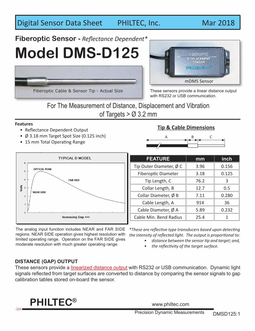
Fiberoptic Sensor - Reflectance Dependent*
*These are reflective type transducers based upon detecting the intensity of reflected light. The output is proportional to:
• distance between the sensor tip and target; and, • the reflectivity of the target surface.
PHILTEC®
Precision Dynamic Measurements
www.philtec.com
Tip & Cable Dimensions
The analog input function includes NEAR and FAR SIDE regions. NEAR SIDE operation gives highest resolution with limited operating range. Operation on the FAR SIDE gives moderate resolution with much greater operating range.
For The Measurement of Distance, Displacement and Vibrationof Targets > Ø 3.2 mm
Model DMS-D125
Digital Sensor Data Sheet PHILTEC, Inc. Mar 2018
DMSD125:1
These sensors provide a linear distance output with RS232 or USB communication.
mDMS Sensor
DISTANCE (GAP) OUTPUTThese sensors provide a linearized distance output with RS232 or USB communication. Dynamic light signals reflected from target surfaces are converted to distance by comparing the sensor signals to gap calibration tables stored on-board the sensor.
Features • Reflectance Dependent Output • Ø 3.18 mm Target Spot Size (0.125 inch) • 15 mm Total Operating Range
FEATURE mm inchTip Outer Diameter, Ø C 3.96 0.156
Fiberoptic Diameter 3.18 0.125Tip Length, C 76.2 3
Collar Length, B 12.7 0.5Collar Diameter, Ø B 7.11 0.280
Cable Length, A 914 36Cable Diameter, Ø A 5.89 0.232
Cable Min. Bend Radius 25.4 1
A B C
Fiberoptic Cable & Sensor Tip - Actual Size
PHILTEC, INC., ANNAPOLIS, MD USA 410-757-4404 Fax 410-757-4404 e-mail [email protected]
* Pk-Pk Resolution is the smallest measurable displacement limited by the sensor’s self-noise.
NOTES:1. These specifications represent best case performance where:
• the target is flat, smooth and highly reflective• the sensor is perpendicular to the target• the sensor is gapped to its range of highest sensitivity (~mid-range) • fiberoptic cable lengths are standard and the cables are not connectorized
2. DMS Control Software includes a data averaging filter for averaging data samples from: 2 samples (the fastest rate) to 4096 samples (highest resolution).
3. Internally, the sensor continuously reads target data at a clock rate of 10,416.75 Hz.
4. ADC AVG = the number of internal readings averaged before sending data out to the PC.
5. Samples/Sec for any ADC AVG setting can be calculated as follows: S/S = 10,416.75 / ADC AVG
DMSD125:2
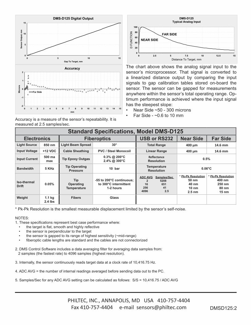
Accuracy is a measure of the sensor’s repeatability. It is measured at 2.5 samples/sec.
Standard Specifications, Model DMS-D125Electronics Fiberoptics USB or RS232 Near Side Far Side
Light Source 850 nm Light Beam Spread 30° Total Range 400 µm 14.6 mmInput Voltage +12 VDC Cable Sheathing PVC / Steel Monocoil Linear Range 400 µm 14.6 mm
Input Current 500 ma max Tip Epoxy Outgas 0.3% @ 200°C
2.4% @ 300°CReflectanceResolution 0.5%
Bandwidth 5 KHz Tip Operating Pressure 10 bar Temperature
Resolution 0.06°C
Iso-thermal Drift 0.05%
Tip Operating
Temperature
-55 to 200°C continuous;to 300°C intermittent
1-2 hours
ADC AVG Samples/Sec 2 5208
16 651 256 41 4096 2.5
* Pk-Pk Resolution 50 nm 40 nm 10 nm 2.5 nm
* Pk-Pk Resolution 400 nm 250 nm 80 nm 15 nm
Weight 1.1 kg2.4 lbs
Fibers Glass
The chart above shows the analog signal input to the sensor’s microprocessor. That signal is converted to a linearized distance output by comparing the input signals to gap calibration tables stored on-board the sensor. The sensor can be gapped for measurements anywhere within the sensor’s total operating range. Op-timum performance is achieved where the input signal has the steepest slope:• Near Side ~50 - 300 microns• Far Side - ~0.6 to 10 mm
NEAR SIDE FAR SIDE
0 2.5 5 7.5 10 12.5 15Distance To Target, mm
0
20
40
60
80
100
D F
UN
CTI
ON
DMS-D125Typical Analog Input
0 1 2 3 4 5 6 7 8 9 10 11 12 13 14 15mm
-2
-1
0
1
2
Mic
rons
>>>Far Side
Accuracy
0 5 10 15Gap To Target, mm
0
5
10
15Se
nsor
Out
put,
mm
DMS-D125 Digital Output
PHILTEC, INC., ANNAPOLIS, MD USA 410-757-4404 Fax 410-757-4404 e-mail [email protected]
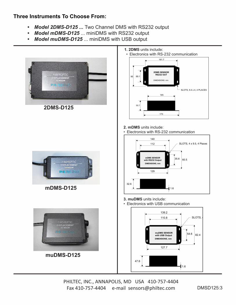
2. mDMS units include: • Electronics with RS-232 communication
1. 2DMS units include: • Electronics with RS-232 communication
3. muDMS units include: • Electronics with USB communication
139.2
110.8
127.7
54.6 82.4
1.6
SLOTS, 4 x 9.5, 4 Places
47.6
muDMS SENSOR
DIMENSIONS, mmwith USB Output
PHILTEC, INC.ANNAPOLIS, MD 21409
DATE DWG. NO.
PHILTEC
muDMS6 Mar '13 muDMS
140
112
129
35.6 60.5
1.6
SLOTS, 4 x 9.5, 4 Places
32.6
mDMS SENSOR
DIMENSIONS, mm
with RS232 Output
PHILTEC, INC.ANNAPOLIS, MD 21409
DATE DWG. NO.
PHILTEC
miniDMS6 Mar '13 mDMS
173
145
50.7
SLOTS, 9.4 x 4, 4 PLACES
161.7
69.195
2DMS SENSORRS232 OUT
DIMENSIONS. mm
muDMS-D125
mDMS-D125
2DMS-D125
Three Instruments To Choose From:
• Model 2DMS-D125 ... Two Channel DMS with RS232 output• Model mDMS-D125 ... miniDMS with RS232 output• Model muDMS-D125 ... miniDMS with USB output
DMSD125:3
PHILTEC, INC., ANNAPOLIS, MD USA 410-757-4404 Fax 410-757-4404 e-mail [email protected]
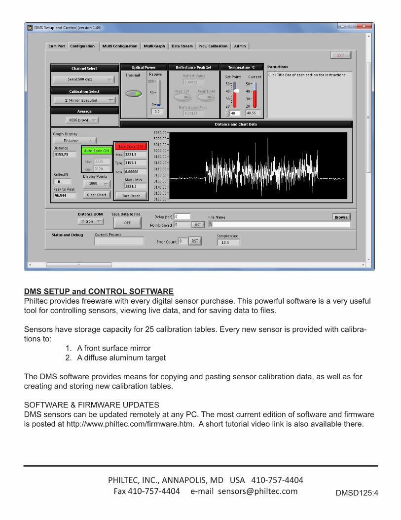
DMS SETUP and CONTROL SOFTWAREPhiltec provides freeware with every digital sensor purchase. This powerful software is a very useful tool for controlling sensors, viewing live data, and for saving data to files.
Sensors have storage capacity for 25 calibration tables. Every new sensor is provided with calibra-tions to:
1. A front surface mirror2. A diffuse aluminum target
The DMS software provides means for copying and pasting sensor calibration data, as well as for creating and storing new calibration tables.
SOFTWARE & FIRMWARE UPDATESDMS sensors can be updated remotely at any PC. The most current edition of software and firmwareis posted at http://www.philtec.com/firmware.htm. A short tutorial video link is also available there.
DMSD125:4