Fiber Units · 2016-03-08 · For an HPF-T005 with a 120 mm sleeve and 5 m ˜ber unit cable...
44
Fiber Units Wide range of models for various applications and environments HPF Series SEARCH BY TYPE OR APPLICATION Select by shape or optical type Select by environment Select by application Accessories A-019 A-025 A-017 A-021 A-024 A-027 A-013 A-015 A-033 A-021 A-035 A-037 A-009 A-029 A-031 A-023 A-033 A-034 A-034 Screw Most generally used. Use by attaching to a bracket, etc. Suitable for installation where space is limited. Use by attaching with the setscrew. Used for target object positioning or in combination with spot lenses. Use to maintain a small distance between target object and switch in a limited space. ght emitted to the side.Use to maintain a small distance between target object and switch in a limited space. Wide light beam.Use for target object with varying detection positions, detection of meandering, etc. Light spread minimized. Use in a place where light intrusion is undesirable. Resistant to ambient influences. Use for target object detection in a limited area. Cylindrical Coaxial Sleeve Side view Area Narrow view Selective reflection Liquid level detection Wefer Mapping Lens unit accessory Long-distance lens / side view unit Other accessories Liquid level detection Heatproof Resistant to high temperatures. Use in environments up to 350 C. Usable in a vacuum. Cable length can be specified. Vacuum-proof Flat/Vane Chemical-proof Suitable for installation where space is limited. Attach directly to casing. Protected with PFA tubing for excellent chemical resistance. Passing chip detection Liquid leak detection A-038 1
Transcript of Fiber Units · 2016-03-08 · For an HPF-T005 with a 120 mm sleeve and 5 m ˜ber unit cable...

Fiber UnitsWide range of models for various applications and environmentsHPF Series
SEARCH BY TYPE OR APPLICATION
Sel
ect b
y sh
ape
or o
ptic
al ty
peS
elec
t by
envi
ronm
ent
Sel
ect b
y ap
plic
atio
nA
cces
sorie
s
A-019
A-025
A-017 A-021
A-024
A-027
A-013 A-015
A-033 A-021
A-035 A-037
A-009
A-029 A-031
A-023
A-033A-034 A-034
ScrewMost generally used.Use by attaching to a bracket, etc.
Suitable for installation where space is limited.Use by attaching with the setscrew.
Used for target object positioning or in combination with spot lenses.
Use to maintain a small distance between target object and switch in a limited space.
ght emitted to the side.Use to maintain a small distance between target object and switch in a limited space.
Wide light beam.Use for target object with varying detection positions, detection of meandering, etc.
Light spread minimized.Use in a place where light intrusion is undesirable.
Resistant to ambient in�uences.Use for target object detection in a limited area.
Cylindrical Coaxial
Sleeve Side view
Area
Narrow view
Selective re�ection
Liquid leveldetection
WeferMapping
Lens unitaccessory
Long-distancelens / side viewunit
Other accessories
Liquid leveldetection
HeatproofResistant to high temperatures.Use in environments up to 350 �C.
Usable in a vacuum.Cable length can be speci�ed.
Vacuum-proof
Flat/Vane
Chemical-proof
Suitable for installation where space is limited.Attach directly to casing.
Protected with PFA tubing for excellent chemical resistance.
Passing chipdetection
Liquid leakdetection
A-038
1

SEARCH BY MODEL NUMBER
Model No. Page
HPF- T001T002T003T004T005T006T007T008T009T010T012T014T015T017T018T019T020T021T021TT021ST021WTT023T024T025T025BT026T028T028LFT029T029ET030T031T032T032ET032E-L02T033T034T034ET034E-L02T035T036T037T038T039T042T043T044T046T047T054-L05VT��
A-009A-013A-009A-013A-017A-017A-019A-009A-013A-009A-027A-027A-017A-027A-027A-021A-021A-025A-025A-025A-025A-021A-009A-009A-009A-019A-023A-023A-029A-029
A-021,087A-013
A-034,073A-034,073A-034,073A-009
A-034,073A-034,073A-034,073A-029A-013A-019A-013A-017A-019A-013A-009A-013
A-033,085A-023A-031
Model No. Page
HPF- D001D002D003D004D005D006D009D010D011D012D013D014D015D018D019D021D022D023D025D026D027D028D028FD028TD029D030D032D032BD033D034D035D035CD036D037D038D039D040D041D042D043D045LFD049VD� �
A-011A-011A-017A-011A-013A-017A-015A-015A-019A-011A-027A-029A-027A-011A-017A-017A-027A-027A-021A-025
A-033,077A-024A-024A-024A-011A-011A-015A-015
A-033,077A-015A-015A-015A-013A-011A-015A-017
A-034,083A-019A-015A-019A-023A-015A-031
Model No.
Lens unit accessory
Page
FE-
HPF-
HPX-
PA-F1PA-FB1PA-FB2PA-FB4PA-L1PA-S1AT10AT13EU02A1EU05EU10LU01LU02LU07LU08LU09VA01VA02-BVJ03VL05VL06PA06
A-038A-038A-038A-038A-037A-037A-038A-038
A-033,086A-038A-038A-035A-035A-035A-035A-035A-032A-032A-032
A-032,037A-032,037A-038
Thru scan(HPF-T��� )
Diffuse scan(HPF-D� � � )
1 2

�Introducing: Combination Amplifiers
HPX-AG series
<Exterior view>
<Operation panel> <Standards compliance>
Hig
h pe
rfor
man
ce •
Adv
ance
d fu
nctio
nsV
olum
eS
tand
ard
Standard
Space-saving(main unit)
Space-saving(expansion unit)
HPX-AG00-1SHPX-AG00-3SHPX-AG00-5S
Typical models
Type Model No.
Double digital displayHigh-sensitivity, ultra-long distance detection Multifunctional models (Alarm output, differential output, two outputs, databank, etc.)
<Exterior view>
<Operation panel><Standards compliance>
Standard
Space-saving(main unit)
Space-saving(expansion unit)
HPX-AG00-1SHPX-AG00-3SHPX-AG00-5S
Typical models
Type Model No.
Double digital displayBuilt for usability(Sensitivity auto-change function, threshold value tracking function)
<Exterior view>
<Operation panel>
<Standards compliance>
Low hysteresis
High sensitivity
HPX-A1HPX-H1
Typical models
Type Model No.
Sensitivity adjuster with indicatorSelf-diagnostic display (output)Slim 10 mm pro�le
HPX-EG series
HPX-A seriesHPX-H series
A-045 Page
A-053 Page
A-061 Page
3

Frontenddia
R20
R20
2m
2m
φ1.2
φ1.2
Shape D
−30 to +70℃
shape
Bendable(10-mm radius)
Extendable
R1
Bend radius Length Amp Mode
Cable
HPX-AG HP42mmFT
nL 40mm20mm
50mm25mm
FTHPX-EG
HPX-HHPX-A
2 m
R4 2m
HPX-AG HP50mmFT
nL 50mm30mm
100mm40mm
FTHPX-EG
HPX-HHPX-A
Free cutUnbreakable
�Introducing: Fiber Customization Services
<List example>
<List example>
<Example model number>
HPF-T001-L05
HPF-T005
HPF-T015
HPF-T037
HPF-D003
HPF-D006
HPF-D011
� Applicable models
�Bend-tolerant �ber unit �Unbreakable fiber unit (stationary bend type)
� Example model number
Thru scan Diffuse scan
For details on the scanning distances with a different cable length, see the Technical Guide (page A-039).The cable cannot be lengthened on some models. For details, please contact our sales staff.
Change the cable lengthIf �ber length is insufficient, you can specify a cable length.
Change the sleeve lengthA range of on-site services are available, such as emergency switch additions and changes, and sample production evaluation.
The standard (base) model No.
Cable length. This can be omitted if length is standard.“S” + 3-digit sleeve length.
� Price: Determined by quantity
� Qty: No minimum (1 cable or more)
� Price: Determined by quantity
� Quantity: No minimum (1 cable or more)
Customizable models have this label.
Indicates element type.
Base model number L02 : Fiber length 2 m
L05 : Fiber length 5 m
L10 : Fiber length 10 m
[Measurement conditions]Roller diameter: 8 mm (4 mm in radius)Load: 500 g
For example, HPF-T008 and -T009 withstand 1,000,000 bends under these conditions without breaking.
Bent ±90°
�Cyclic bending test (reference)
For use in moving environments
R4 R1 / R2
Thanks to multi-core structure bundling several 100s of fiber elements, bending the cable does not attenuate the light level.
Conventional fiber core structure Unbreakable fiber
core structure
Even if the cable is bent at a small radius, the light level does not change.
A-017 / A-019 Page
For an HPF-T005 with a 120 mm sleeve and 5 m �ber unit cable
HPF-T005-S120L05 is the model number.
*
*
�Introducing: Element Types
Material of element
Plastic
Performance/Feature
Multi-component glass Two types, 200�C and 350�C
350�C
General-purpose
Heatproof
Heatproof
Vacuum
Bend tolerant
Unbreakable
3 4

Reference data
Reference dataReference data
A-077
Reference data Reference data
Reference data
Reference data
A-073
A-083
A-087
A-021
A-015
A-025
Par
alle
l dis
plac
emen
t
Scanning distance X (mm)
Cataloglisting
Pipediameter
Presenceof liquid
Absenceof liquid
HPF-T032HPF-T032E
6 mm
8 mm
HPF-T034HPF-T034E
12 mm
19 mm
Combination amplifiers: HPX-AG series(Sensing mode : nL3For 8 mm dia. pipe only : nL2)
Received light level display value
Received light level display value
Item Amount
σ 3 μm max.
Max - Min 11 μm
Received light level display value
109876543210-10
-8
-6
-4
-2
0
2
4
6
8
10
X
Y
HP
Sensing model
Ft
Cataloglisting
Presenceof liquid
Absenceof liquid
HPF-D027
HPF-D033
Combination amplifiers: HPX-EG series(Sensing model : nL3)
Cataloglisting
Presenceof liquid
Absenceof liquid
Switchfloating
HPF-D040
Combination amplifiers: HPX-EG series(Sensing mode: nL3)
Combination amplifiers: HPX-AG series(Sensing model: HP3)
Combination amplifiers: HPX-AG series(Sensing model : HP3)
Light level change characteristics
Combination amplifiers: HPX-AG series(Sensing model : HP, FT)
Detection area characteristics
Combination amplifiers: HPX-AG series(Sensing model : HP3)
Excess gain
20
5 10 15 20
40
60
80
100
120
140
160
180
Ligh
t int
ensi
ty (
%)
Displacement (mm)
Double layer Diagonal installation
301
10
100
Exc
ess
gain
fact
or (
times
)
Scanning distance (mm)
1000
70 110 150
HPF-D026HPF-D002
50 90 130 170 190 200
Gold wire detection[Type] Coaxial (Diffuse scan)[Catalog listing] HPF-D009
Coaxial
Lead frame size 35 mm×150 mm
Lead frame detection[Type] Area (Diffuse scan)[Catalog listing] HPF-D026
Area
Target object
Liquid level detection[Type] Specialized use (Thru scan)[Catalog listing] HPF-T032_, HPF-T034_
Liquid level detection
Liquid level detection[Type] Specialized use (Thru scan)[Catalog listing] HPF-D027, HPF-D033
Liquid level detection
Wafer projection detection[Type] Narrow view (Thru scan)[Catalog listing] HPF-T020
Narrow view
Wafer mapping[Type] Narrow view (Thru scan)[Catalog listing] HPF-T030
Narrow view
Liquid leak detection[Type] Specialized use (Diffuse scan)[Catalog listing] HPF-D040
Liquid leak detection
Silicon wafer (300 mm)
Target object
Silicon wafer (300 mm)
Target object
Gold wire (�17 μm)
Target object
Water
Target object
Water
Target object
Water
Target object
Note: The possibility of detection, as well as the measurement performance and degree of accuracy, are affected by the actual working conditions. Before using the �ber unit, carry out a careful operation check.
*Light intensity is 100 % when there is no wafer.
�Edge detection repeatability accuracy
This section gives application case studies along with evaluation data using actual workpieces.
CASE STUDIES (WITH ACTUAL WORKPIECE DATA)
Applications
5

Reference data
Reference dataReference data
A-077
Reference data Reference data
Reference data
Reference data
A-073
A-083
A-087
A-021
A-015
A-025
Par
alle
l dis
plac
emen
t
Scanning distance X (mm)
Cataloglisting
Pipediameter
Presenceof liquid
Absenceof liquid
HPF-T032HPF-T032E
6 mm
8 mm
HPF-T034HPF-T034E
12 mm
19 mm
Combination amplifiers: HPX-AG series(Sensing mode : nL3For 8 mm dia. pipe only : nL2)
Received light level display value
Received light level display value
Item Amount
σ 3 μm max.
Max - Min 11 μm
Received light level display value
109876543210-10
-8
-6
-4
-2
0
2
4
6
8
10
X
Y
HP
Sensing model
Ft
Cataloglisting
Presenceof liquid
Absenceof liquid
HPF-D027
HPF-D033
Combination amplifiers: HPX-EG series(Sensing model : nL3)
Cataloglisting
Presenceof liquid
Absenceof liquid
Switchfloating
HPF-D040
Combination amplifiers: HPX-EG series(Sensing mode: nL3)
Combination amplifiers: HPX-AG series(Sensing model: HP3)
Combination amplifiers: HPX-AG series(Sensing model : HP3)
Light level change characteristics
Combination amplifiers: HPX-AG series(Sensing model : HP, FT)
Detection area characteristics
Combination amplifiers: HPX-AG series(Sensing model : HP3)
Excess gain
20
5 10 15 20
40
60
80
100
120
140
160
180
Ligh
t int
ensi
ty (
%)
Displacement (mm)
Double layer Diagonal installation
301
10
100
Exc
ess
gain
fact
or (
times
)
Scanning distance (mm)
1000
70 110 150
HPF-D026HPF-D002
50 90 130 170 190 200
Gold wire detection[Type] Coaxial (Diffuse scan)[Catalog listing] HPF-D009
Coaxial
Lead frame size 35 mm×150 mm
Lead frame detection[Type] Area (Diffuse scan)[Catalog listing] HPF-D026
Area
Target object
Liquid level detection[Type] Specialized use (Thru scan)[Catalog listing] HPF-T032_, HPF-T034_
Liquid level detection
Liquid level detection[Type] Specialized use (Thru scan)[Catalog listing] HPF-D027, HPF-D033
Liquid level detection
Wafer projection detection[Type] Narrow view (Thru scan)[Catalog listing] HPF-T020
Narrow view
Wafer mapping[Type] Narrow view (Thru scan)[Catalog listing] HPF-T030
Narrow view
Liquid leak detection[Type] Specialized use (Diffuse scan)[Catalog listing] HPF-D040
Liquid leak detection
Silicon wafer (300 mm)
Target object
Silicon wafer (300 mm)
Target object
Gold wire (�17 μm)
Target object
Water
Target object
Water
Target object
Water
Target object
Note: The possibility of detection, as well as the measurement performance and degree of accuracy, are affected by the actual working conditions. Before using the �ber unit, carry out a careful operation check.
*Light intensity is 100 % when there is no wafer.
�Edge detection repeatability accuracy
This section gives application case studies along with evaluation data using actual workpieces.
CASE STUDIES (WITH ACTUAL WORKPIECE DATA)
Applications
5 6

Reference data
Reference data
Reference data
Reference data
Reference data
Reference data
UNDERSTANDING THE GRAPHS
Combination amplifiers: HPX-EG series (Sensing model : nL3)
Light level change characteristicsCombination amplifiers: HPX-MA series(SENS:FINE RESP:NORMAL)
T021WT
T021T
T021
Light level change characteristicsCombination amplifiers: HPX-EG series (Sensing model : nL3)
Scanning distance (mm)
Exc
ess
gain
fact
or (
times
)
1
10
1000
4 52 7 9 10
100
13 6 8Notes: �The characteristic changes depending on the fall velocity and attitude of the chip.
�This chart shows data for when the adapter for a small-diameter pipe (HPF-AU04) is attached.
Exc
ess
gain
fact
or (
times
)
0
10
1000
Scanning distance (mm)15 205 30 40 45
100
110 25 35
Plain glassVapor-deposited glass
Black mask
50
-15
25
75
Rate
of r
ecei
ved
light
leve
l cha
nge
(%)
Displacement
100
-5 0-10 5 10 15
50
0
Note: Optical center is aligned at 0 mm
-0.4
90
Rate
of r
ecei
ved
light
leve
l cha
nge
(%)
Time (ms)
100
0 0.2-0.2 0.4 0.6 0.8
80
70
Xmm
0.50 1 1.5 2
Exc
ess
gain
fact
or (
times
)
Sca
nnin
g re
nge
1
10
100
Scanning distance (mm)
Sensing distance
1 mm0.5 mm
0.3 mm
Scanning distance
Front of component
Rear of component
-2 mm
-1 mm
Focal Distance
+1 mm
+2 mm
Received light level display value
Received light level display value
Scanning distance Mark Reject mark
-2 mm
-1 mm
Focal Distance
+1 mm
+2 mm
Combination amplifiers: HPX-AG series (Sensing model : Ft3)
Combination amplifiers: HPX-AG series(Sensing model :nL3)
Excess gain
Combination amplifiers: HPX-AG series(Sensing model : HP3)
Excess gain
AG
Standard target object
Chip face/back discrimination[Type] Coaxial (Diffuse scan)/ Micro-Spot Lens[Catalog listing] HPF-D034, HPF-LU07
Coaxial/Micro-Spot Lens
Detection of meandering [Type] Area (Thru scan) [Catalog listing] HPF-T021T�
Area
Substrate "Bad" mark detection[Type] Coaxial (Diffuse scan) / Micro-Spot Lens[Catalog listing] HPF-D038, HPF-LU08
Coaxial/Micro-Spot Lens
Target object
(Back)Target size 1 mm × 0.5 mm
Gold patternApprox. 1 mm dia.
Reject mark*The reject mark is applied to the gold pattern using an oil-based red felt pen.
Passing chip detection[Type] Specialized use (Thru scan)[Catalog listing] HPF-D027, HPF-D033
Passing chip detectionBlack mask
Glass detection[Type] Selective reflection (Diffuse scan) [Catalog listing] HPF-D028T
Selective reflection
Glass detection[Type] General-purpose screw (Diffuse scan) [Catalog listing] Fiber: HPF-D002 Amplifiers:HPX-AG series (HP3)
Screw
Target object
Target object size 1 mm×0.5 mm
Target object
Target object
Opaque Sheet
Glass substrate
Target object
�Excess gain
The excess gain indicates the magnitude of output from the light-receiving element relative to the amount of light received by the fiber unit (which varies depending on the distance). The graph shows that at a distance of 1, the output from the light-receiving element is 10 times the level required for operation. This surplus is available in case there is a decrease in the incoming light level due to misalignment of the optical axis, dirt on the light-receiving element, etc.
Note: On an excess gain graph, the minimum operating level of the amplifier is set at 1.
The detection a rea is a characteristic used for diffuse scans. The graph shows the operation points of the fiber switch when a standard target object (white paper) is moved perpendicular to the optical axis at the maximum sensitivity setting. This illustrates the extent of detectable light around the fiber unit.
Note: For the excess gain graph, the minimum operating level of amplifier unit is set as 1.
�Detection area
*Detection availability, measurement performance, and accuracy also depend on actual working conditions. Use the �ber unit after carrying out in advance an operation check and evaluation.
Thickness 0.3 mm
Target object
A-085
A-035
A-035
A-015A-015
A-015A-015
A-025
A-011
A-024
7

Reference data
Reference data
Reference data
Reference data
Reference data
Reference data
UNDERSTANDING THE GRAPHS
Combination amplifiers: HPX-EG series (Sensing model : nL3)
Light level change characteristicsCombination amplifiers: HPX-MA series(SENS:FINE RESP:NORMAL)
T021WT
T021T
T021
Light level change characteristicsCombination amplifiers: HPX-EG series (Sensing model : nL3)
Scanning distance (mm)
Exc
ess
gain
fact
or (
times
)
1
10
1000
4 52 7 9 10
100
13 6 8Notes: �The characteristic changes depending on the fall velocity and attitude of the chip.
�This chart shows data for when the adapter for a small-diameter pipe (HPF-AU04) is attached.
Exc
ess
gain
fact
or (
times
)
0
10
1000
Scanning distance (mm)15 205 30 40 45
100
110 25 35
Plain glassVapor-deposited glass
Black mask
50
-15
25
75
Rate
of r
ecei
ved
light
leve
l cha
nge
(%)
Displacement
100
-5 0-10 5 10 15
50
0
Note: Optical center is aligned at 0 mm
-0.4
90
Rate
of r
ecei
ved
light
leve
l cha
nge
(%)
Time (ms)
100
0 0.2-0.2 0.4 0.6 0.8
80
70
Xmm
0.50 1 1.5 2
Exc
ess
gain
fact
or (
times
)
Sca
nnin
g re
nge
1
10
100
Scanning distance (mm)
Sensing distance
1 mm0.5 mm
0.3 mm
Scanning distance
Front of component
Rear of component
-2 mm
-1 mm
Focal Distance
+1 mm
+2 mm
Received light level display value
Received light level display value
Scanning distance Mark Reject mark
-2 mm
-1 mm
Focal Distance
+1 mm
+2 mm
Combination amplifiers: HPX-AG series (Sensing model : Ft3)
Combination amplifiers: HPX-AG series(Sensing model :nL3)
Excess gain
Combination amplifiers: HPX-AG series(Sensing model : HP3)
Excess gain
AG
Standard target object
Chip face/back discrimination[Type] Coaxial (Diffuse scan)/ Micro-Spot Lens[Catalog listing] HPF-D034, HPF-LU07
Coaxial/Micro-Spot Lens
Detection of meandering [Type] Area (Thru scan) [Catalog listing] HPF-T021T�
Area
Substrate "Bad" mark detection[Type] Coaxial (Diffuse scan) / Micro-Spot Lens[Catalog listing] HPF-D038, HPF-LU08
Coaxial/Micro-Spot Lens
Target object
(Back)Target size 1 mm × 0.5 mm
Gold patternApprox. 1 mm dia.
Reject mark*The reject mark is applied to the gold pattern using an oil-based red felt pen.
Passing chip detection[Type] Specialized use (Thru scan)[Catalog listing] HPF-D027, HPF-D033
Passing chip detectionBlack mask
Glass detection[Type] Selective reflection (Diffuse scan) [Catalog listing] HPF-D028T
Selective reflection
Glass detection[Type] General-purpose screw (Diffuse scan) [Catalog listing] Fiber: HPF-D002 Amplifiers:HPX-AG series (HP3)
Screw
Target object
Target object size 1 mm×0.5 mm
Target object
Target object
Opaque Sheet
Glass substrate
Target object
�Excess gain
The excess gain indicates the magnitude of output from the light-receiving element relative to the amount of light received by the fiber unit (which varies depending on the distance). The graph shows that at a distance of 1, the output from the light-receiving element is 10 times the level required for operation. This surplus is available in case there is a decrease in the incoming light level due to misalignment of the optical axis, dirt on the light-receiving element, etc.
Note: On an excess gain graph, the minimum operating level of the amplifier is set at 1.
The detection a rea is a characteristic used for diffuse scans. The graph shows the operation points of the fiber switch when a standard target object (white paper) is moved perpendicular to the optical axis at the maximum sensitivity setting. This illustrates the extent of detectable light around the fiber unit.
Note: For the excess gain graph, the minimum operating level of amplifier unit is set as 1.
�Detection area
*Detection availability, measurement performance, and accuracy also depend on actual working conditions. Use the �ber unit after carrying out in advance an operation check and evaluation.
Thickness 0.3 mm
Target object
A-085
A-035
A-035
A-015A-015
A-015A-015
A-025
A-011
A-024
7 8

[Related pages]
Shape A
�0.5R1
ShapeSizeType CoreScanning distance (mm)
Model No.Min.
detectable size (mm)Bend radius Length DistanceAmp Mode
Cable
HPF-T024
4�0.25 HPF-T008
�0.75 HPF-T044
�1.0 HPF-T025
�1.0 HPF-T003
�1.4 HPF-T001
16�0.25 HPF-T033
�1.0 HPF-T025B
�1.0 HPF-T010
HPX-AG HP 14040FT
nL
5025
FTHPX-EG
HPX-HHPX-A
2 m
R4 2 m
R20 2 m
R2 2 m
R20 2 m
R20 2 m
R4 2 m
R2 2 m
R20 2 m
M3
Straight
M4
M4
M4
Bolt
Elbow
Shape B
Shape C
Shape C
Shape D
Shape E
Shape F
HPX-AG HP 18052FT
nL
10040
FTHPX-EG
HPX-HHPX-A
300
HPX-AG HP 675195FT
nL
150
220110
FTHPX-EG
HPX-HHPX-A
HPX-AG HP 900260FT
nL
300150
FTHPX-EG
HPX-HHPX-A
HPX-AG HP1,200350FT
nL
400200
FTHPX-EG
HPX-HHPX-A
HPX-AG HP2,175630FT
nL
800400
FTHPX-EG
HPX-HHPX-A
HPX-AG HP 900260FT
nL
265130
FTHPX-EG
HPX-HHPX-A
HPX-AG HP 900260FT
nLFT
HPX-EG
HPX-HHPX-A
HPX-AG HPFTnLFT
HPX-EG
855245
300150
HPX-HHPX-A
−30 to +70˚C
−30 to +70˚C
−30 to +70˚C
−30 to +70˚C
−30 to +70˚C
�0.005
�0.01
�0.005
�0.005
�0.005
�0.01
�0.01
�0.005
�0.005
5029
6038
220130
310180
410240
770450
280160
310180
300170
−30 to +70˚C
For combined lenses, see
For diffuse scan type,see page A-011.
Straight type
Bolt type
Elbow type
*For scanning distances of the sensing modes, see the Technical Guide (page A-043).*Response times for the sensing types: HP 5 ms, nL 1 ms, and FT 250 µs.*The values shown in the Minimum detectable size column were obtained with optimal scanning distance and sensitivity settings (HPX-AG).
OUDER GUIDE
�Thru scan
Most generally used. Use by attaching to a bracket, etc.
Screw Thru scan
A-037
Free cut
Free cut
Free cut
Free cut
Free cut
Free cut
Free cut
Free cut
Free cut
Unbreakable
Unbreakable
Unbreakable
Bendtolerant
Bendtolerant
Lens attachable
Lens attachable
Lens attachable
Lens attachable
9

NOTEWORTHY
Shape A
Shape F
11M4
M2.6
2000
�2.7(SUS)
5 155
HPF-T010
Core dia.�1.0
Shape C
11 2000
HPF-T001
HPF-T003
HPF-T025
Core dia.�1.4
Core dia.�1.0
Core dia.�1.0
Shape B
11 2000
HPF-T044
Core dia.�0.752.5
HPF-T024
HPF-T008
Core dia.�0.5
Core dia.4 × �0.25
�1
11 2000
�1
M4(SUS)
M2.6
4.4
73
2000
�2.2
1
Epoxy resin
30°
30°
7
�8.5
HPF-T025B
Core dia.�1.03
3
�2.2�2.5(SUS)
R5
Shape D
11
M4
HPF-T033
�1.3Core dia.16 × �0.253.2 M2.6
3
�2.2�2.2M2.6
Shape E
M3
(SUS)
(SUS)
(SUS)M3 (SUS)
M4 (SUS)
20003
Products allowing either nut or setscrew installation are available for flexible operability, maintenance parts consolidation, and other factors.
Attachment method selectable
�Applicable model number
HPF-T025B
Nut installation Setscrew installation
From Type Model no.
Thru scan
Thru scan
Thru scan
Straight
Straight
Bolt
HPF-T033
HPF-T044
HPF-T025B
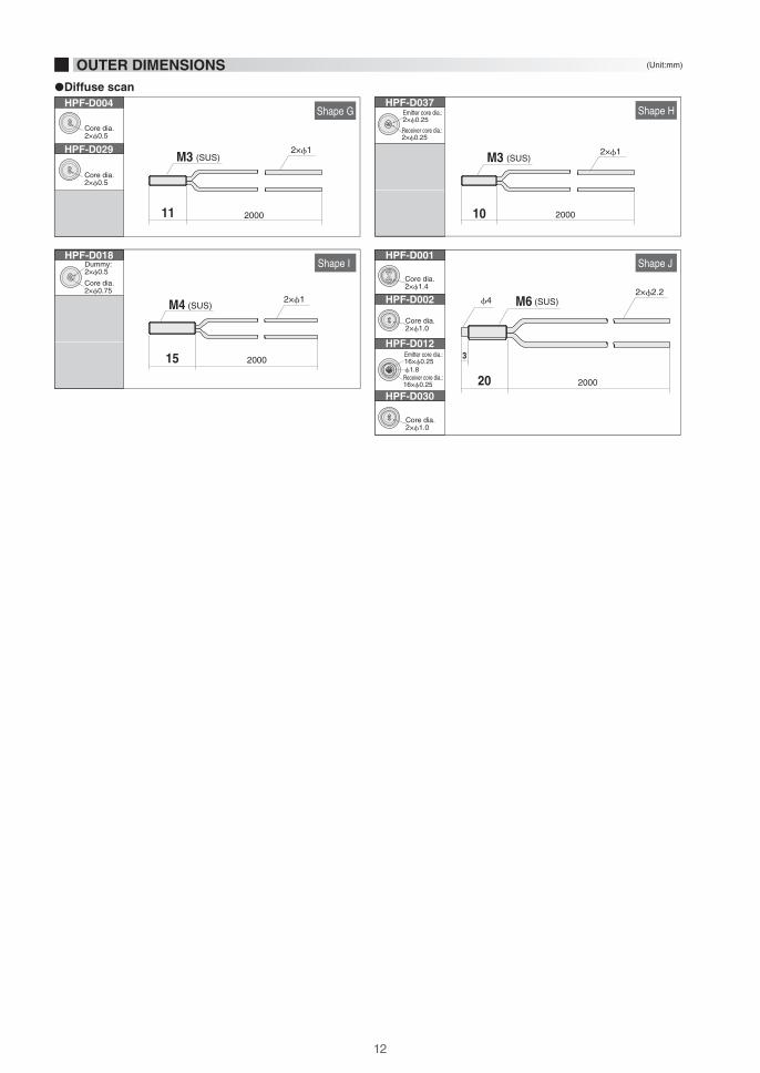
OUTER DIMENSIONS (Unit:mm)
�Thru scan
D-Shape cutout
9 10

SizeType Core Model No.
Shape G
Shape H
Bend radius Length
Cable
HPF-D029
Receiverand
emitter�0.5
HPF-D004
Receiverand
emitter2�0.25
HPF-D037
HPX-AG HP 258FT
nL 105FT
HPX-EG2 m
2 m
2 m
M3
Straight
M6
M4
HPX-AG HP 10534FT
nL 4325
4020
FTHPX-EG
HPX-HHPX-A
84
HPX-HHPX-A
105
HPX-HHPX-A
HPX-AG HP 206FT
nL 85FT
HPX-EG
Shape
�0.005
�0.005
�0.005
Min. detectable size (mm)
*For scanning distances of the sensing modes, see the Technical Guide (page A-044).*Scanning distances for diffuse scan are obtained with a standard target object (plain white paper).*Response times for the sensing types: HP 5 ms, nL 1 ms, and FT 250 µs.*The values shown in the Minimum detectable size column were obtained with optimal scanning distance and sensitivity settings (HPX-AG).
Scanning distance (mm)
DistanceAmp Mode
Straight type Elbow type
Bolt type
Shape I Receiverand
emitter�0.75
HPF-D0182 m
8040
HPX-HHPX-A
HPX-AG HP 20065FT
nL 7546FT
HPX-EG �0.005
Shape J Receiverand
emitter�1.0
HPF-D030
Receiverand
emitter16�0.25
HPF-D012
Receiverand
emitter�1.4
HPF-D001
Receiverand
emitter�1.0
HPF-D002
2 m
2 m
2 m
R1
R15
R4
R15
R2
R4
R20
R20 2 m
8040
HPX-HHPX-A
10050
HPX-HHPX-A
230120
HPX-HHPX-A
15080
HPX-HHPX-A
HPX-AG HP 21069FT
nL 8550FT
HPX-EG
HPX-AG HP 25080FT
nL 10055FT
HPX-EG
HPX-AG HP530170FT
nL 210120FT
HPX-EG
HPX-AG HP 400130FT
nL 15090FT
HPX-EG
�0.005
�0.005
�0.005
�0.005
OUDER GUIDE
�Diffuse scan
Most generally used. Use by attaching to a bracket, etc.
Screw Diffuse scan
−30 to +70˚C
−30 to +70˚C
−30 to +70˚C
−30 to +70˚C
Free cutUnbreakable
Bendtolerant
For thru scan see page A-009.
[Related pages]
Free cut
Free cut
Free cut
Free cut
Free cut
Free cut
Free cut
Unbreakable
Bendtolerant
Receiverand
emitter�0.5
11
HPF-D004
HPF-D029
Core dia.2�0.5
Core dia.2�0.5
11 2000 10
HPF-D037
Receiver core dia.:2�0.25
Emitter core dia.:2�0.25
Shape G Shape H
15 2000
Shape IHPF-D001
HPF-D002
HPF-D012
HPF-D030
Core dia.2�1.4
Core dia.2�1.0
Core dia.2�1.0
�1.8Receiver core dia.:16�0.25
Emitter core dia.:16�0.25
20
3
Shape J
M4 (SUS)
2000
M32�1
(SUS) M3 2�1(SUS)
2000
M62�2.2
(SUS)�42�1
HPF-D018
Core dia.2�0.75
Dummy:2�0.5
OUTER DIMENSIONS (Unit:mm)
�Diffuse scan
11 12

�0.25R4
ShapeSizeType Core Model No.Bend radius Length
Cable
HPF-T038
4�0.25 HPF-T009
4�0.25 HPF-T046
�0.125 HPF-T036
�0.5 HPF-T043
�1.0 HPF-T004
�1.0 HPF-T031
�0.005
�0.01
�0.01
�0.005
�0.005
�0.005
�0.005
�0.01�1.4 HPF-T002
HPX-AG HP 3710FT
nL
126
FTHPX-EG
HPX-HHPX-A
0.5 m
R4 2 m
R4 2 m
R4 0.5 m
R15 2 m
R20 2 m
R2 2 m
R20 2 m
�1.5
�1
Straight
�2
�3
Scanning distance (mm)
DistanceAmp Mode
HPX-AG HP 18052FT
nL
10040
FTHPX-EG
HPX-HHPX-A
HPX-AG HP 18052FT
nL
10040
FTHPX-EG
HPX-HHPX-A
HPX-AG HP 185FT
nL
63
FTHPX-EG
HPX-HHPX-A
HPX-AG HP 30085FT
nL
10050
FTHPX-EG
HPX-HHPX-A
HPX-AG HP1,200350FT
nL
400200
FTHPX-EG
HPX-HHPX-A
HPX-AG HP 900260FT
nL
300150
FTHPX-EG
HPX-HHPX-A
HPX-AG HP2,175630FT
nL
800400
FTHPX-EG
HPX-HHPX-A
127
6038
6038
63
10055
410240
310180
770450
Shape A
Shape B
Shape C
Shape D
Shape E
Shape G
Shape F
Shape G
Min. detectable size (mm)
ShapeSizeType Core Model No.Bend radius Length
Cable
�0.005
�0.005
Scanning distance (mm)
DistanceAmp Mode
Receiverand
emitter2�0.25
HPF-D036
Receiverand
emitter�0.5
HPF-D005
R4 1 m
R15 2 m
�1.5
�3
Straight
206
84
10534
4020
HPX-HHPX-A
HPX-AG HPFTnLFT
HPX-EG
HPX-HHPX-A
HPX-AG HPFTnLFT
HPX-EG
Shape H
Shape I
85
4325
Min. detectable size (mm)
*For scanning distances of the sensing modes, see the Technical Guide (page A-043).*Scanning distances for diffuse scan are obtained with a standard target object (plain white paper).*Response times for the sensing types: HP 5 ms, nL 1 ms, and FT 250 µs.*The values shown in the Minimum detectable size column were obtained with optimal scanning distance and sensitivity settings (HPX-AG).
For head dia. of less than �1.0 mm (thru scan) or �1.5 mm (diffuse scan), select from sleeve-type switches.
A-037
A-017
A-019
Compatible lenses
Side-view switches
[Related pages]
Straight type
�Thru scan
�Diffuse scan
OUDER GUIDE
Suitable for installation where space is limited. Use by attaching with the setscrew.
Cylindrical
−30 to +70˚C
−30 to +70˚C
−30 to +70˚C
−30 to +70˚C
−30 to +70˚C
−30 to +70˚C
−30 to +70˚C
−30 to +70˚C
−30 to +70˚C
−30 to +70˚C
Bendtolerant
Bendtolerant
Bendtolerant
Free cut
Free cut
Free cut
Free cut
Free cut
Free cut
Free cut
Unbreakable
Lens attachable
13

6
22 2000
50020
�3.5 Nylon resin
13
�1�0.7 Polyester resin �2.2
10 500
25
15 2000
10 2000
Shape H
Shape C
Shape E
Shape G
Shape I
Shape B
Shape D
Shape F
Shape H
15 20003
8 2000
15 200015
10 1000(100)
2013
HPF-T009
HPF-T036
Core dia.4 × �0.25
Core dia.�0.125
HPF-T031
Core dia.�1.0
Core dia.2 × �0.5
HPF-D036
Receiver core dia.:2 × 0.25 dia.
Emitter core dia.:2 × 0.25 dia.
HPF-T046
HPF-T038
HPF-T043
Core dia.�0.25
Core dia.�0.5
Core dia.4 × �0.25
HPF-T004
HPF-T002
Core dia.�1.0
Core dia.�1.4
HPF-D005
(SUS)
�1.5 (SUS) �1
�2 (SUS) �1
�3 (SUS) �2.2M2.6
�3 (SUS) 2�1
�1.5 (SUS) �1
�2.2 Nylon resin�1.5
�1.2 Polyethylene resin
(SUS)
�3 (SUS) �2.2
2�3.5 (plastic)
�1.5
�3(SUS)2�2.2
(SUS)
�1.2
�1.2 Polyethylene tube
NOTEWORTHY
OUTER DIMENSIONS (Unit:mm)
FE-PA-L1(For long distance and narrow beam types)
FE-PA-S1(For side view types)
HPF-T038HPF-T004
Smallest fiber unit head dia. (1.0 mm) in the industry Compatible lens units are available for cylindrical types
�Thru scan
�Diffuse scan
13 14

Emitter :�0.25
Receive :6�0.25
R4
SizeType Core Model No.Bend radius Length
Cable
HPF-D034
Emitter :�0.5
Receive :4�0.25
HPF-D032
Emitter :�0.5
Receive :4�0.25
HPF-D010
Emitter :�0.5
Receive :9�0.25
HPF-D035
Emitter :�0.5
Receive :4�0.25
HPF-D032B
Emitter :�0.5
Receive :9�0.25
HPF-D038
Emitter :�1.0
Receive :16�0.25
HPF-D009
Emitter :�0.5
Receive :4�0.25
HPF-D042
Emitter :�0.5
Receive :9�0.25
HPF-D035C
�0.005
�0.005
�0.005
�0.005
�0.005
�0.005
�0.005
�0.005
�0.005
HPX-AG HP 6019FT
nL
2513
FTHPX-EG
HPX-HHPX-A
0.5 m
Emitter: R1Receiver: R4
Emitter:R1Receiver:R4
2 m
R15 2 m
R15 2 m
1 m
R15 2 m
R20 2 m
R15 2 m
R15 2 m
M3Straight
Straight
M4
M3
M6
�2
�3
Bolt
Shape
HPX-AG HP 4615FT
nL
1810
FTHPX-EG
HPX-HHPX-A
HPX-AG HP 8628FT
nL
4020
FTHPX-EG
HPX-HHPX-A
HPX-AG HP 9543FT
nL
5025
FTHPX-EG
HPX-HHPX-A
HPX-AG HP 4615
1810
FTnLFT
HPX-EG
HPX-HHPX-A
HPX-AG HP 9543FT
nL
5025
FTHPX-EG
HPX-HHPX-A
HPX-AG HP 400130FT
nL
15080
FTHPX-EG
HPX-HHPX-A
HPX-AG HP 8628FT
nL
4020
FTHPX-EG
HPX-HHPX-A
HPX-AG HP 9543FT
nL
5025
FTHPX-EG
HPX-HHPX-A
Scanning distance (mm)
DistanceAmp Mode
Shape A
Shape B
Shape D
Shape E
Shape F
Shape G
Shape H
Shape I
−30 to +70˚C
−30 to +70˚C
−30 to +70˚C
−30 to +70˚C
−30 to +70˚C
−30 to +70˚C
−30 to +70˚C
−30 to +70˚C
2515
1810
3521
5029
Emitter :�0.5
Receive :9�0.25
HPF-D049�0.005R4 1 m
HPX-AG HP 16055FT
nL
6034
FTHPX-EG
HPX-HHPX-A
Shape C
−30 to +70˚C
6038
1810
5029
15090
3521
5029
Straight type Bolt type
*For scanning distances of the sensing modes, see the Technical Guide (page A-044).*Scanning distances for diffuse scan are obtained with a standard target object (plain white paper).*Response times for the sensing types: HP 5 ms, nL 1 ms, and FT 250 µs.*The values shown in the Minimum detectable size column were obtained with optimal scanning distance and sensitivity settings (HPX-AG).
A-035
For compatible micro-spot lenses
[Related pages]
�Diffuse scan
OUDER GUIDE
Used for target object positioning or in combination with spot lenses.
Coaxial
Lens attachable
Lens attachable
Lens attachable
Lens attachable
Lens attachable
Lens attachable
Lens attachable
Min. detectable size (mm)
Free cutUnbreakable
Unbreakable
Free cut
Free cut
Free cut
Free cut
Free cut
Free cut
Free cut
Free cut
Bendtolerant
15

18
16
50020
13
2�3.5(plastic)
�1.6(Receiver)
23
�3
1522 2000
2000
Shape A
Shape F
Shape H
Shape B
Shape C
18 2000
HPF-D010
HPF-D038
HPF-D042
Receiver core dia.:4�0.25(Dummy:5�0.25)
Emitter core dia.:�0.5
HPF-D032
Receiver core dia.:9�0.25
Emitter core dia.:�0.5
Receiver core dia.:4�0.25(Dummy:5�0.25)
Emitter core dia.:�0.5
Receiver core dia.:4�0.25
Emitter core dia.:�0.5
HPF-D035
Receiver core dia.:9�0.25
Emitter core dia.:�0.5
Shape D
20 2000
2�2.2
6
9.5
V Groove
15
2000
M6
Shape G
Shape I
Shape E
Receiver core dia.:6�0.25
Emitter core dia.:�0.25
HPF-D049
HPF-D009
Receiver core dia.:16�0.25
Emitter core dia.:�1.0
HPF-D035C
Receiver core dia.:9�0.25
Emitter core dia.:�0.5
HPF-D032B
Receiver core dia.:4�0.25(Dummy:5�0.25)
Emitter core dia.:�0.5
HPF-D034
M3 (SUS) �0.9(Emitter) 2�2.2 M3 (SUS) 2�1
18 2000
3.5
11.51000
1
30°
30°
5.5
�6.5Epoxy resin
M3 (SUS)
2.2
2�1
3
(SUS)
2�1.25�3 (SUS)2.8
2�0.1�2 (SUS)�3 (SUS)
�3M3 (SUS)2�1.25
5
M3 (SUS) 2�1.25
11 10005
�1.3
�1.0M3 (SUS)
�3
Receiver core dia.:9�0.25
Emitter core dia.:�0.5
Detection fiber
Receiver fiber
TargetTarget
Standard
General diffuse scan type used conventionally
Used in combination with micro-spot lenses, for positioning use, etc.
Coaxial
Coaxial fiber is recommended for use with micro-spot lenses and applications requiring highly precise positioning.
OUTER DIMENSIONS (Unit: mm)
�Diffuse scan
NOTEWORTHY
15 16

Front end dia. Core Model No.Bend radius Length
Cable Scanning distance (mm)
DistanceAmp ModeShape
Min. detectable size (mm)
�0.125
�0.25
�1.0
�1.0
R4
Front end dia. Core Model No.Bend radius Length
Cable
HPF-T039
HPF-T015
HPF-T005
HPF-T006
�0.005
�0.005
�0.005
�0.005
HPX-AG HP 185FT
nL
63
FTHPX-EG
HPX-HHPX-A
0.5 m
R15 2 m
R20
R20
2 m
2 m
�0.4
�0.5
�1.2
�1.2
HPX-AG HP 3710FT
nL
126
FTHPX-EG
HPX-HHPX-A
HPX-AG HP350FT
nL
400200
FTHPX-EG
HPX-HHPX-A
HPX-AG HP1,200
1,200
350FTnL
400200
FTHPX-EG
HPX-HHPX-A
Shape A
Shape B
Shape C
Shape D
−30 to +70˚C
−30 to +70˚C
−30 to +70˚C
−30 to +70˚C
53
127
410240
410240
Scanning distance (mm)
DistanceAmp ModeShape
Min. detectable size (mm)
Receiverand
emitter�0.25
Receiverand
emitter�0.25
Receiverand
emitter�0.5
Receiverand
emitter�0.5
Receiverand
emitter�1.0
HPF-D039
HPF-D019
HPF-D006
�0.005
�0.005
�0.005
�0.005
�0.005
R4 0.5 m
R15 0.5 m
R15 2 m
�0.82
�0.82
�1.2
HPX-AG HP 206FT
nL
42
FTHPX-EG
HPX-HHPX-A
HPX-AG HP 206FT
nL
42
FTHPX-EG
HPX-HHPX-A
HPX-AG HP 10534FT
nL
4020
FTHPX-EG
HPX-HHPX-A
HPF-D021R15 2 m�1.5
HPX-AG HP 8628FT
nL
4020
FTHPX-EG
HPX-HHPX-A
HPF-D003R20 2 m�2.5
HPX-AG HP 400130FT
nL
15080
FTHPX-EG
HPX-HHPX-A
Shape E
Shape F
Shape G
Shape H
Shape I
−30 to +70˚C
−30 to +70˚C
−30 to +70˚C
−30 to +70˚C
−30 to +70˚C
42
42
4325
3521
15090
*For scanning distances of the sensing modes, see the Technical Guide (page A-043).*Scanning distances for diffuse scan are obtained with a standard target object (plain white paper).*Response times for the sensing types: HP 5 ms, nL 1 ms, and FT 250 µs.*The values shown in the Minimum detectable size column were obtained with optimal scanning distance and sensitivity settings (HPX-AG).
Straight type
�Thru scan
�Diffuse scan
A-008
A-019
Sleeve-length customization
Side-view sensing
[Related pages]
OUDER GUIDE
Use to maintain a small distance between target object and switch in a limited space.
Sleeve
Free cut
Free cut
Free cut
Free cut
Free cut
Free cut
Free cut
Free cut
Bendtolerant
Extendable
Extendable
Bendable(10-mm radius)
Extendable
Bendable(10-mm radius)
Extendable
Bendable(10-mm radius)
Bendable(10-mm radius)
17

1510 2000
�0.5
105 500
�0.82
500
25
5
�2.5
�0.4
1565
1010
2000
�1.2
1565
HPF-T005
Core dia.�1.0
HPF-T006
Core dia.�1.0
2000
Note: Area that cannot be bentNote: Area that cannot be bent
Note: Area that cannot be bent
20 2000
2�2.2
�2.5
1165
65
2000
2�1�1.2
HPF-T039Core dia.�0.125
0.4
Shape A Shape B
Shape D
Shape F
Shape C
Shape E
Shape G
Shape I
HPF-D039
Core dia.2 × �0.25
Core dia.2 × �0.5
HPF-D006
Core dia.2 × �1.0
HPF-D003
5
15 15 500
�3 (SUS)
HPF-D019
Core dia.2 × �0.25
(SUS)�2.2 (Nylon resin)(SUS)
�2.2(SUS) M4(SUS)
2�2.2(SUS)
�2.5 (SUS)2�1
(SUS)
M4 (SUS)(SUS)
10 10
�1�3 (SUS)
(SUS)
1010
�1.2 �2.2(SUS) �3(SUS)
M6 (SUS)
(SUS)
1010
�0.82
HPF-T015
Core dia.�0.25
1015 2000
HPF-D021
Core dia.2 × �0.5
Shape H
2�1�1.5 �3(SUS)(SUS)
Note: Area that cannot be bent
OUTER DIMENSIONS (Unit: mm)
�Thru scan
�Diffuse scan
Note NoteNote Note
Note Note
Note Note
17 18

Center of optical axis
(From front end)
Front end dia. Core Model No.
Bend radius Length
Cable Scanning distance (mm)
DistanceAmp Mode
Min. detectable size (mm)
Shape
�0.5
�0.5
�0.5
�0.5
R5
R1
Center of optical axis
(From front end)
Front end dia. Core Model No.
Bend radius Length
Cable
HPF-T037
HPF-T026
HPF-T007
HPF-T042
�0.005
�0.005
�0.005
�0.005
HPX-AG HP 5215FT
nL
2010
FTHPX-EG
HPX-HHPX-A
1 m
2 m
R15 2 m
R5 2 m
�0.88
�1
�1
�3
HPX-AG HP 5215FT
nL
2010
FTHPX-EG
HPX-HHPX-A
HPX-AG HP 16548FT
nL
6030
FTHPX-EG
HPX-HHPX-A
HPX-AG HP660190FT
nL
240120
FTHPX-EG
HPX-HHPX-A
Scanning distance (mm)
DistanceAmp Mode
Min. detectable size (mm)
Shape A
Shape B
Shape C
Shape D
−30 to +70˚C
−30 to +70˚C
−30 to +70˚C
−30 to +70˚C
Shape
2011
2011
5533
220130
Receiverand
emitter�0.5
Receiverand
emitter�0.5
Receiverand
emitter�1.0
HPF-D011
HPF-D041
HPF-D043
�0.005
�0.005
�0.005
R15 2 m
R15 2 m
R20 2 m
�2
�2
�6
HPX-AG HP 4013FT
nL
158
FTHPX-EG
HPX-HHPX-A
HPX-AG HP 4013FT
nL
158
FTHPX-EG
HPX-HHPX-A
HPX-AG HP 16052FT
nL
5032
FTHPX-EG
HPX-HHPX-A
Free cut
Free cut
Free cut
Shape E
−30 to +70˚C
Shape F
−30 to +70˚C
Shape G
−30 to +70˚C
1710
1710
6540
1.5
0.6
1.5
1.5
1.5
1.5
1.5
Straight type
*For scanning distances of the sensing modes, see the Technical Guide (page A-043).*Scanning distances for diffuse scan are obtained with a standard target object (plain white paper).*Response times for the sensing types: HP 5 ms, nL 1 ms, and FT 250 µs.*The values shown in the Minimum detectable size column were obtained with optimal scanning distance and sensitivity settings (HPX-AG).
�Thru scan
�Diffuse scan
A-021
A-008
Narrow view sensing
Sleeve-length customization
[Related pages]
OUDER GUIDE
Light emitted to the side.
Use to maintain a small distance between target object and switch in a limited space.
Side view
Extendable
Extendable
Unbreakable
Free cut
Free cut
Free cut
Free cut
19

NOTEWORTHY
Unique
featureSelection
point
HPF-T007
HPF-T037
HPF-D011
HPF-T026
HPF-D041
HPF-T042
HPF-D043
12
1215
2000151.5 Optical axis
1515 2000
2�1
2000151000
0.6 Optical axis
0.3
45°
1.5
15
�1�0.88
1
45°
1.5
1.5 Optical axis
1
1 2
45°
45°
1.5
35 2000
1540
35 2000
2�2.2
2000
2.2
D-shape cutout
2.8
D-shape cutout
2.2
D-shape cutout
2.2
D-shape cutout
2.8
D-shape cutout
2.6
D-shape cutout
1.5 Optical axis
1
45°
1.5
(1dia.)
5.7
D-shape cutout
Shape B
Shape D
Shape F
Shape A
Shape C
Shape E
Shape G
1.5 Optical axis
0.5
45°
1.5
1.5 Optical axis
1
45°
1.5
Optical axis
�2.5(SUS)
�1�2.5(SUS)�1
2�1�3(SUS)
�6
�1�2.5(SUS)
�3 �2.2(SUS)
�2 �2.8(SUS)
Optical axis
Optical axis
Optical axis
(SUS)
Optical axis
1.5 Optical axis
Optical axis
�1(SUS)
(SUS)
�2 (SUS)
(SUS)
All side view types have D-shape cutout on the fiber unit head.This can greatly reduce adjustment man-hours during installation.
The distance from the front end to the center of the optical axis depends on the product structure. Select the model that is suitable for your application.
In detection of small component dislocation, the distance from the front end to the center of the optical axis is important.
OUTER DIMENSIONS (Unit: mm)
Optical axis
�Thru scan
�Diffuse scan
×D-shape cutout
0.6
The D-shape cutout perpendicular to the optical axis facilitates alignment.
Optical axis position for side view unit
(Example)
19 20

ShapeLightemitter Bend radius Length
Cable Scanning distance (mm)
DistanceAmp Mode
1,400840
1,500920
1,200730
310180
ShapeLightemitter
Model No.Bend radius Length
Cable
R20 HPF-T019�2.1
HPX-AG HPFTnLFT
HPX-EG2 m2.5°
HPX-HHPX-A
1,500750−30 to +70˚C
Shape C
HPF-T020�2.6R20 2 m3°
HPX-AG HPFTnL
1,600800
FTHPX-EG
HPX-HHPX-A
−30 to +70˚C
Shape D
HPF-T023�1.7R15 2 m1.5°
HPX-HHPX-A
HPX-AG HP3,600
1,050
4,1001,200
4,5001,310
FTnLFT
HPX-EG
1,200600−30 to +70˚C
Shape B
HPF-T030�1.5 �0.005
�0.1
�0.1
�0.1
R5 2 m1.5°
Top
Side
Top
Top
Side
HPX-HHPX-A
HPX-AG HP 500305FT
nL
350175
FTHPX-EG
−30 to +70˚C
Shape A
� HPF-D025R15 2 m�HPX-HHPX-A
HPX-AG HP 2020
2020
FTnLFT
HPX-EG 2016
−30 to +70˚C
Shape E
�0.005
Scanning distance (mm)
DistanceAmp Mode
(Light from top) (Light from side)
*For scanning distances of the sensing modes, see the Technical Guide (page A-043).*Scanning distances for diffuse scan are obtained with a standard target object (plain white paper).*Response times for the sensing types: HP 5 ms, nL 1 ms, and FT 250 µs.*The values shown in the Minimum detectable size column were obtained with optimal scanning distance and sensitivity settings (HPX-AG).
A-019
A-017
If a narrow beam is not required:
Sleeve-type units :
Side-view units :
[Related pages]
�Thru scan
�Diffuse scan
OUDER GUIDE
Light spread minimized. Use in a place where light intrusion is undesirable.
Narrow view
Free cut
Free cut
Free cut
Free cut
Free cut
Directionalangle
(half angle)
Effectivelens
diameter
Min. detectable size (mm)
Directionalangle
(half angle)Model No.
Effectivelens
diameter
Min. detectable size (mm)
21

NOTEWORTHY
11
3(Optical axis)
Glass lens
200017
�2.8
11 20001715 20009
4.31.5
10.5
1
2.8
1.4
�1
�2
30 2000(2.8)
Optical axis
4.31.3
�4
HPF-T019 HPF-T020
HPF-T023HPF-T030
HPF-D025
Glass lens
20.5(10.7)2000
2�1
3.8
D-shape cutoutShape C
Shape B
Shape D
Shape A
Shape E
(SUS)(SUS)
7.5
3.5 8
7.4
�2.2(SUS)
�4 M5 (SUS) (Aluminum)
31.2
(SUS)Glass lens M4(SUS) �2.2
�2.3 (SUS)Glass lens M4(SUS) �1
Narrow view types are available also by combination with long-distance lenses and side-view lenses.
(Typical examples)
*For lens units, see page A-037.
Optical configuration Lens unit Fiber unit
Top
Top
Side
Side
FE-PA-L1
HPF-VL06
FE-PA-S1
HPF-VL05
Directional angle (half angle)
Approx. 3°
Approx. 3°
Approx. 10°
Approx. 8°
HPF-T003
HPF-T003
HPF-T003
HPF-T003
OUTER DIMENSIONS (Unit: mm)
�Thru scan
�Diffuse scan
21 22

HPF-T028LFBrass (Ni plated)
�0.5(Core dia)
2000
2.5
2×R22×R
3108.5
10 6
2.4
4 2�2.3�1
5200010
1015
3.3
HPF-T028
HPF-T054-L05
SUS
2×M3
�2.2
SUS
2×M3
5
10
1015
3.3
2000
2�2.2
Shape D
2�0.35
Shape BShape A
HPF-D045LFShape C
9
22
2530 (5)
12.315.2
6
(8)
12
4×C0.5
5000
Housing (black PPS)Adhesive(black epoxy-based resin)
2.3 2.3
4.6
(Light from top) (Light from �at)
OUTER DIMENSIONS (Unit: mm)
Suitable for installation where space is limited. Attach directly to casing.
Flat/Vane
ShapeLightemitter Core Model No.
Bend radius Length
CableType
Scanning distance (mm)
DistanceAmp Mode
Min. detectable size (mm)
ShapeLightemitter Core Model No.
Bend radius Length
Cable
HPF-T028
HPF-T028LF
�0.5 �0.005
�0.005�1.0
HPX-AG HP 14040FT
nL
5025
FTHPX-EGR1
R5
2 m
2 m
Top
Flat
HPX-AG HP 21060FT
nL
8040
FTHPX-EG
HPX-HHPX-A
HPX-HHPX-A
Type
Flat
5029
8047
Scanning distance (mm)
DistanceAmp Mode
Shape A
−30 to +70˚C
Receiverand
emitter�1.0
HPF-D045LFR2 2 m
HPX-AG HP 9330FT
nLFT
HPX-EG
3517
FlatFlat
HPX-HHPX-A
�3721
Shape D
−30 to +70˚C
Shape B
−30 to +70˚C
HPF-T054-L05�0.005�0.5R15 5 m�
HPX-AG HP 66FT
nL
66
FTHPX-EG
HPX-HHPX-A
Vanetype
66
Shape C
−30 to +70˚C
Min. detectable size (mm)
*For scanning distances of the sensing modes, see the Technical Guide (page A-043).*Scanning distances for diffuse scan are obtained with a standard target object (plain white paper).*Response times for the sensing types: HP 5 ms, nL 1 ms, and FT 250 µs.*The values shown in the Minimum detectable size column were obtained with optimal scanning distance and sensitivity settings (HPX-AG).
�Thru scan
�Diffuse scan
OUDER GUIDE
Free cut
Free cut
Free cut
Free cutUnbreakable
Unbreakable
�Thru scan
�Diffuse scan
Optical axis center: 1.75
Optical axis center: 1.5
Optical axis center
23

HPF-D028 HPF-D028T Mounting hole: 2�3.2
4×90°
4�6Aluminum (black anodized)
2000197 4
(4.5)
3
12
2�6
2×90°
2�3.2
2�1
4
2000166 6.5
18
HPF-D028FMounting hole: 2�3.2
2�1
4×90°
4�6
4
200018.662.6 6.5
18
2.2
15.5
Acrylic resin Heat-resistant ABS resin
11.5
2.5
2�1
Heat-resistant ABS resinSensing surface
(Light from �at)
OUTER DIMENSIONS (Unit: mm)
Resistant to ambient influences. Use for target object detection in a limited area.
Selective re�ection
�Diffuse scan
Light emitter Model No.Bend radius Length
Cable
HPF-D028
HPF-D028T
HPF-D028F
R15
R15
R15
2 m
2 m
2 m
Top
Flat
�0.005
�0.005
�0.005
HPX-AG
HP 2.5±0.5
2.5±0.5
2.5±0.5
2.5±0.5
nL
SF
FT
HP 7.4±1.6
7.4±1.6
7.4±1.2
7.4±1.6
nL
SF
FT
HP
nL
nL
nL
SF
FT
HPX-AG
HPX-AG
HPX-EG
HPX-EG
5.2±1.6
5.2±1.6
5.2±1.0
5.2±1.6
Scanning distance (mm)
DistanceAmp ModeShape
*For scanning distances of the sensing modes, see the Technical Guide (page A-044).*Scanning distances for diffuse scan are obtained with a standard target object (plain white paper).*Response times for the sensing types: HP 5 ms, nL 1 ms, and FT 250 µs.*The values shown in the Minimum detectable size column were obtained with optimal scanning distance and sensitivity settings (HPX-AG).
�Diffuse scan
OUDER GUIDE
Shape A
−30 to +70˚C
Shape B
−30 to +70˚C
Shape C
−30 to +70˚C
Free cut
Free cut
Free cut
Min. detectablesize (mm)
Shape BShape A
Shape C
3 (optical axis)
Sensing surface
(Light from top)
23 24

ShapeType Model No.Bend radius Length
Optical con�guration
Area width(mm)
Min. detectable size (mm)
Scanning distance (mm)
DistanceAmp Mode
NOTEWORTHY
R4
R15
ShapeType Model No.Bend radius Length
Cable
Cable
HPF-T021
HPF-T021T
HPF-T021WT
HPX-AG HP 780225FT
nL
250125
FTHPX-EG
HPX-HHPX-A
2 m
2 m
R15 2 m
Array
Screen
Optical con�guration
15
5.25
30
Area width(mm)
HPX-AG HPFTnL
1,200600
FTHPX-EG
HPX-HHPX-A
HPX-AG HPFTnLFT
HPX-EG
HPX-HHPX-A
−30 to +70˚C
−30 to +70˚C
Shape B
Shape D
�0.2
�0.2
�0.4
3,6001,050
3,6001,750
2,0001,000
270160
1,200710
HPF-T021SR15 2 m
Flat
Flat
Flat
Side 15
HPX-AG HPFTnL
1,100550
FTHPX-EG
HPX-HHPX-A
−30 to +70˚C
Shape C
�0.2
3,4501,000
1,100670
2,0001,100
Shape A
Min. detectable size (mm)
Scanning distance (mm)
DistanceAmp Mode
HPF-D026R4 2 mFlatArray 10.85
HPX-AG HP 26585FT
nL
10050
FTHPX-EG
HPX-HHPX-A
Shape E
−30 to +70˚C
�0.005100
60
−30 to +70˚C
*For scanning distances of the sensing modes, see the Technical Guide (page A-043).*Scanning distances for diffuse scan are obtained with a standard target object (plain white paper).*Response times for the sensing types: HP 5 ms, nL 1 ms, and FT 250 µs.*The values shown in the Minimum detectable size column were obtained with optimal scanning distance and sensitivity settings (HPX-AG).
Light from sideLight from �at
Small diameter fibers are aligned in a row.Smaller and slimmer switch heads are also available.
Light is collimated using the lens.This increases the scanning range and makes the light uniform.
Type Features
Screen type
Array type
�Thru scan
�Diffuse scan
A-033
Small part passage sensing
[Related pages]
OUDER GUIDE
Free cut
Free cut
Free cut
Free cut
Free cut
Wide light beam. Use for target object with varying detection positions, detection of meandering, etc.
Area
Bendtolerant
Bendtolerant
25

Note
Material: Transparent polyester �lm (black print on back)
HPF-D026
HPF-T021S
HPF-T021THPF-T021
HPF-T021WT
17
15
4
14.5 10.7
10
38.331
19
5
23 18
3
3018.5
71.3
45
64
12
2000
13
20.6
20.615
2.8
4.8
10.6
(7.1
)
10.6
5
2000
HPX-T021T
�Accessory
Shape A
Shape C
Shape E
Shape B
Shape D
15
1.5 5.5 3.5
15×0.5
7 1129
22.8
Paper mat0.50.5
7×0.5 11×2
2000
15.6
15.68.1
8.12.810
84.8
4.85
2×M3C1
PBT resin SUS insert
15×
0.35
(=5.
25)
16�0.25(core dia.)
0.351.3�2.2
7
2
4×90°
4�62�3.2
�2.2
2000Heat-resistant ABS resin
Acrylic resin
38.331
197�2.2
2000Heat-resistant ABS resin
15
4
14.5 10.7
10
4×90°
4�62�3.2Acrylic resin
24�6
2�3.2
�2.2
Heat-resistant ABS resin
Acrylic resin4×90°
Optical axis (enlarged)31
×0.3
5(=1
0.85
)
0.351.3
Magni�ed view of optical axis
4.8
32�0.25(core diameter)
SUS insert2×M3PBT resin
C1
2�2.2
HPX-T021WT
30
2.7 7.7
30×0.5
2060
0.50.5
20×0.5
Note
Material: Transparent polyester �lm (black print on back)
OUTER DIMENSIONS (Unit: mm)
HPF-T021T comes with slits.Use the appropriate slit with the unit to achieve the desired scanning distance and resolution.The slits can be bought as parts. Model No : HPX - PA07
HPF-T021WT comes with slits.Use the appropriate slit with the unit to achieve the desired scanning distance and resolution.
�Thru scan
�Diffuse scan
25 26

SizeHeatproof Element Model No.Bend radius Length
CableShape
Min. detectable size (mm)
Scanning distance (mm)
DistanceAmp Mode
R25
SizeHeatproof Element Model No.Bend radius Length
Cable
�1.0 �0.005
�0.01
�0.005
�0.005
�1.5
�1.0
�1.0
HPX-AG HP 690200FT
nL
250120
FTHPX-EG
R35
R15
R15
2 m
2 m
1 m
2 m
Straight
Straight
Straight
Straight
105�C
150�C
200�C
350�C
HPX-AG HP1,200350FT
nL
400200
FTHPX-EG
HPX-HHPX-A
HPX-HHPX-A
HPX-HHPX-A
HPX-HHPX-A
HPX-AG HP 615175FT
nL
200100
FTHPX-EG
HPX-AG HP 660190FT
nL
250120
FTHPX-EG
Shape A
Shape B
Shape C
Shape D
Shape
240140
410240
14080
220130
R25 2 m
R35 2 m
R15 1 m
HPX-AG HP 19085FT
nLFT
HPX-EG
HPX-AG HP 400130FT
nLFT
HPX-EG
HPX-AG HP 17055FT
nLFT
HPX-EG
10050
15080
5050
Straight105�C
Straight150�C
Straight200�C
Straight350�C
HPX-HHPX-A
HPX-HHPX-A
HPX-HHPX-A
HPF-T012*1
HPF-T017*1
HPF-T018
HPF-T014
HPF-D013*1
HPF-D022*1
HPF-D023
HPF-D015R25 2 m
HPX-AG HP 16075FT
nL
9030
FTHPX-EG
HPX-HHPX-A
Shape E
Shape F
Shape G
Shape H
Receiverand
emitter�1.0
Receiverand
emitter�1.5
�1.4
�1.5
�0.005
�0.005
�0.005
�0.005
10055
15090
7042
8550
Scanning distance (mm)
DistanceAmp Mode
Heat resistant to 350�CHeat resistant to 200�C
*For scanning distances of the sensing modes, see the Technical Guide (page A-043).*Scanning distances for diffuse scan are obtained with a standard target object (plain white paper).*Response times for the sensing types: HP 5 ms, nL 1 ms, and FT 250 µs.*The values shown in the Minimum detectable size column were obtained with optimal scanning distance and sensitivity settings (HPX-AG).
*1. If a �ber unit is continuously used in an environment where it is at the upper limit of the operating temperature range, the detection distance will decrease. When selecting a �ber unit, be sure to take the ambient temperature into account so that the switch is not continuously operating near its limits.
�Thru scan
�Diffuse scan
[Related pages]
A-037
Compatible lenses
Resistant to high temperatures. Use in environments up to 350�C.
Heatproof
Free cut
Free cut
Free cut
Free cut
−30 to +105˚C
−60 to +150˚C
−30 to +200˚C
−30 to +350˚C
−30 to +105˚C
−60 to +150˚C
−30 to +200˚C
−30 to +350˚C
Lens attachable
Lens attachable
Lens attachable
Min. detectable size (mm)
OUDER GUIDE
27

11
M2.6
Silicone tube (plastic)
Siliconetube
2000
151000
Note: Area where bending is not allowed
(10)Note
(10) 10 13Note
�5
17200030
−60~+350�C −30~+70�C
10 13
�2.2�4 �5 (plastic)
17 2000
�2.85
20 2000 17 2000
3 13
2�2.2�4.9
14
1000
23(30)272 13
�9�4
17200025
30 60 10 133−60~+110�C −30~+70�C−60~+350�C
�4�10(SUS)
Shape A
Shape C
Shape E
Shape G
Shape B
Shape D
Shape F
Shape H
HPF-T012
HPF-T018
Effective dia.:�1.0
Glass�ber: �1.0(�0.05×320)
Glass �ber: �1.4(2×�0.05×320)
HPF-D013
Effective dia.:2�1.0
HPF-D023
HPF-T017
HPF-T014
Core dia.�1.5
�0.05×370(Glass �ber)
HPF-D022
2�2.2
Core dia.2�1.5
�1.5(2×(�0.05×370))(Glass �ber)
HPF-D015
�2.2M4 (SUS)
3
M4 (SUS)
(SUS)
(SUS)
M2.6 �2.2
3
�2.2M4 (SUS)
M6
3
2�2.2
M6
10
Note: Area where bending is not allowed
(10)Note
Silicone tube2�5 (plastic)
2�2.2
M6(SUS)
�5
2�5 (plastic)
2�2.2Stainlesssteel tube
Operating temperature range
Stainless steel tube
M4 (SUS)
3
Operating temperature range
M2.6
M6 (SUS)�4
NOTEWORTHY
Use the lens unit appropriate for your application.
*Select a lens with the desired heat resistance.
*Compatible lens units P. A-037
Heatproof temp. Lens Type
200�C
350�C
FE-PA-L1
FE-PA-S1
HPF-VL06
HPF-VL05
LongdistanceSide
LongdistanceSide
Sensitivity
Approx. ×6
-
Approx. ×10
-
OUTER DIMENSIONS (Unit: mm)
151
�Thru scan
�Diffuse scan
27 28
SizeLight emitter Model No.
Min. detectable size (mm)Bend radius Length
Cable Scanning distance (mm)
DistanceAmp ModeShape
SizeLight emitter Model No.
Min. detectable size (mm)Bend radius Length
Cable
HPF-T029
HPF-T029E
HPF-T035
HPX-AG HP4,5001,310FT
nL
1,500750
FTHPX-EGR20
R20
R20
2 m
2 m
2 m
�4.7
�4.7
�4.7
Top
Top
Side
HPX-AG HP 825240FT
nL
270130
FTHPX-EG
HPX-HHPX-A
HPX-HHPX-A
HPX-HHPX-A
HPX-AG HP 1,030300FT
nL
340170
FTHPX-EG
Shape A
Shape B
Shape C
�0.1
�0.1
�0.1
1,500880
280160
350210
HPF-D014
PFA area:R80
Cable area:R20
2 m
HPX-AG HP 17055FT
nLFT
HPX-EG
5050
�6Top
Shape D
HPX-HHPX-A
�7042
Scanning distance (mm)
DistanceAmp ModeShape
*For scanning distances of the sensing modes, see the Technical Guide (page A-043).*Scanning distances for diffuse scan are obtained with a standard target object (plain white paper).*Response times for the sensing types: HP 5 ms, nL 1 ms, and FT 250 µs.*For chemical resistance of �uorine-resin, see the Technical Guide (page A-039).*The values shown in the Minimum detectable size column were obtained with optimal scanning distance and sensitivity settings (HPX-AG).
Light from top Light from side
[Related pages]
A-033
Wet process switches for level & leak detection
Usage notes
�Thru scan
�Diffuse scan
OUDER GUIDE
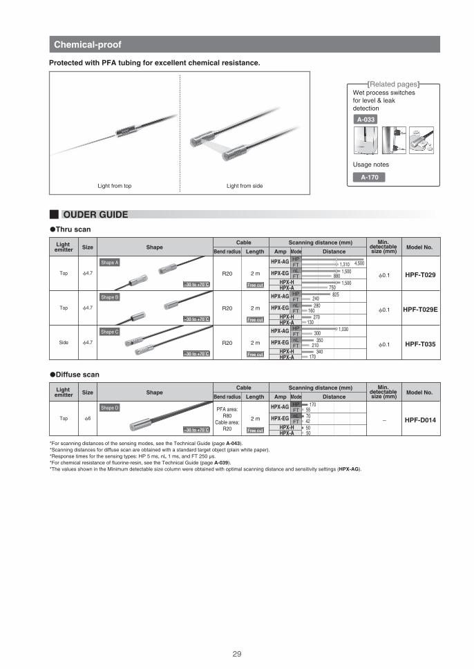
Protected with PFA tubing for excellent chemical resistance.
Chemical-proof
−30 to +70˚C
−30 to +70˚C
−30 to +70˚C
−30 to +70˚C
Free cut
Free cut
Free cut
Free cut
A-170
29

NOTEWORTHY
Simply cut the PFA-jacketed cable to length and insert as is into the ampli�er.
HPF-T035
14.7 2000 300
5
�4.7
15.8
(5)
2000 3004.8 (Optical axis)
�4.7
300200011
Effective dia.�2.8
16 2000
1900
HPF-D014
Core dia.2 × �1.0
Shape A
Shape C
Shape B
Shape D
HPF-T029
Lens dia.:�3.0
HPF-T029E
Core dia.�1.0(PFA) �2.2(PFA) �1.3
Side view unit
�4.7 (PFA) �1.3
(PFA)�2.2(PFA) �1.3
�6 (PFA)�5(PFA)
2�2.2
�2.2(PFA)
Fiber cut with a cutter can be directly connected to an ampli�er.
PFA tube must be stripped off before inserting �ber.
Saves spaceInstallation man-hours greatly reduced
Simply cut the PFA-jacketed cable.
Tube has small outside diameter of 2.2 mm, which can save considerable space compared with previous models. Bend radius is also greatly improved.
Insert as is into the ampli�er. The insertion area requires no PFA working.
OUTER DIMENSIONS (Unit: mm)
�Thru scan
�Diffuse scan
Conventionally After improvement
Fiber cut with a cutter can be directly connected
Tube has small outside diameter of 2.2 mm, which can save considerable space compared with previous models. Bend radius is also greatly improved.
After improvementThis is
thedifference!
29 30

0
1
−VT
−VD
ModelBase model No.
HPFHead shape Description
Cable length Ordering increment
Coupler side shape Cable length
�S����
�S����
�S����
Thru scan
Diffuse scan
Straight
Elbow (VT type only)
Straight
Elbow
25 mm to 500 mm
550 mm to 1500 mm
1600 mm to 5000 mm
25 mm
50 mm
100 mm
S
E
−VTHPF 0 S −S1000 (Typical examples)
100000
5
10
15
20
25
30
35
40
2000 3000 4000
Fiber length [mm]
100000
50
100
150
200
250
300
2000 3000 4000
Fiber length [mm]
Scanning distance[mm] Characteristics of cable length versus scanning distance
Thru scan
�Scanning distance characteristicsDiffuse scan
5000
Scanning distance[mm] Plot of cable length versus scanning distance
5000
*For �ber units for air, HPF-VA01 is used for calculation.*Scanning distances for diffuse-scan were obtained using a standard target object (plain white paper).*For calculations, nL was used as the sensing type for HPX-AG.
:HPX-AG:HPX-H
:HPX-AG:HPX-H
Heat resistant to 350 ˚C Heat resistant to 200 ˚C
Product con�guration
Amp unitOptional units Fiber unit for airVacuum �bers Optical couplers
[Related pages]
Usage notes
Cable drawing
CONFIGURATION OF VACUUM FIBER MODEL NUMBERS
Speci�ed cable length
Speci�ed cable length
HPF-VD�� -S���� HPF-VT�� -S����
A-154
CHART
Usable in a vacuum. Cable length can be speci�ed.
Vacuum-proof
31

22 82.5
(8)
1.4
45
7
6.8
2.5
SUS
M5×0.8
Air sideVacuum side
8
(9.23)
�1.2�3.5
�10
�4.1(SUS)
8 1 8
�12
Head shape (straight)
(Elbow)
Head shape (elbow)
(straight)
�2.9(SUS)
�4.6(SUS)
20M4 (SUS)30
3
3
35
20
HPF-VT0� -S����
HPF-VD0� -S����
HPF-V��E-S���� Coupler side shape
HPF-VA� �
HPF-VJ03
HPF-VT1� -S� � � �
HPF-V� �S-S� � � � Coupler side shape
Fitting: (SUS)Inside screw: M5, depth of 7
152000
2 10
11
HPF-VL06HPF-VL05
M2.6
4
9.9
�2.8(optical axis):
6.3(optical axis)
�3.5(SUS)
�8(SUS)
11.75
6
M2.6
25
37.5
3
27
(R10)
15
�2.9(SUS)
M4 (SUS)
M2.6�4
M6×0.75(SUS)
�4 �12(SUS)
�2.9(SUS)
(SUS)
8 111
24.5
11.5
15�3.5
�10
�4.1(SUS)
End fitting: (SUS)Inside screw: M5, depth of 7enlargement
�4
�8(SUS)
�4.1
�3.5(SUS)
8�1.2
�2.2
HPF-VT0� HPF-VT1�
HPF-VD0�
Glass �berbundle dia.: �1.2(�0.05×380)
Glass �berbundle dia.: �1.7
HPF-VA01
HPF-VA02-BCore dia.: �1.0
Core dia.: �1.5
(2×�0.05×380)
Glass �berbundle dia.: �1.2(�0.05×380)
End fitting: Stainless steel (SUS)Inside screw: M5, depth of 7
Glass lens�4Straight knurl
M2.6
Mountable plate thickness:8~10 mm
Optical coupler(two units)
Fiber unit for air(two units in a pair)
Long-distance lens unit(two units)
Side-view unit(two units)
Product name Shape Heatproof
200�C
70�C
150�C
350�C
350�C
Model No.
HPF-VJ03
HPF-VA01
HPF-VA02-B
HPF-VL06
HPF-VL05
Other speci�cations
-
Cable length: 2 mBend radius: R20
Cable length: 2 mBend radius: R35
Scanning distance: ×10
-
OPTIONS FOR VACUUM FIBER UNIT
OUTER DIMENSIONS (Unit: mm)
Free cut
Free cut
enlargement
31 32

Fiber Units for Small Parts Passage Detection
Reliable detection of small parts moving through the pipe.
All-resin structure ensures no metal contamination.
Select by application
A-085
Contact-Type Liquid Level Fiber Units
Problems due to liquid accumulation are reduced by Azbil corporation’s innovative front end structure.
Product lineup includes a small-diameter model (�4) for easier cable routing.
A-077
�Thru scan
*Area width can be changed with attachments (sold separately).*Use HPF-T047 in combination with HPF-EU02A1.*Use HPF-EU02A1 for scanning distances of 50 cm or more.
HPF-T047R4 0.5 m12 mm
ShapeArea width Model No.Bend radius Length
Cable
HPF-EU02A1R25Mixed �ver unit 2 m
−30 to +70˚C
−30 to +70˚C
OUDER GUIDE
�Diffuse scan
HPF-D033PFA area:
R30Cable area:
R15
2 m�4
ShapeType Model No.Bend radius Length
Cable
HPF-D027PFA area:
R40Cable area:
R25
�6 2 m
OUDER GUIDE
Free cut
Free cut
Free cut
−30 to +105˚C
−30 to +105˚C
Reliably detects parts in the pipe.
Weighs only 12 g.
For operation inside a moving device, highly bend-tolerant optical �ber cable are used.
Wire lead-out follows the pipe, allowing a smaller footprint.
By changing the attachment, the width of the detection area can be adjusted to match the pipe diameter.
[Related pages]
[Related pages]
33

Pipe-Mounted Liquid Level Fiber Units
A 16-axis array of light beams greatly eliminates interference from water droplets and air bubbles.
� Product lineup includes differing detection methods for fail-safe detection.
� Can be used for pipe diameters of 3 to19 mm.
A-073
�Thru scan (Attached to pipe)
�Diffuse scan
Liquid Leakage Fiber Units
PFA jacket affords outstanding ease of routing.
� Space-saving switch head height of only 9.9 mm
� Can be used in explosion-proof atmospheres because the cable is optical �ber.
A-083
R20
Shape(mm) Model No.Bend radius Length
Cable
HPF-D0405 m
−30 to +70˚C
Use with PFA transparent pipe with wall thickness of 1 mm.Depending on the pipe actually used, as well as the liquid thru scan and refractive ratios, �ber unit detection may not be reliable, so be sure to test the operation before use.If the �ber unit is used with other than the recommended pipe, material, or wall thickness, please test before use or consult our sales staff.
[Related pages]
[Related pages]
HPF-T034E
HPF-T034E-L02
HPF-T034
R4Polyethylene
PFA5 m�8~�19 mm
(3/4B)Liquid-absentreceived light
ShapeCompatible
pipe dia.Type Model No.Bend radius Length
Cable
2 m
Coating material
HPF-T032E
HPF-T032E-L02
HPF-T032
R4Polyethylene
PFA
�3~�13 mmLiquid-presentreceived light
2 m
5 m
−30 to +70˚C
−30 to +70˚C
OUDER GUIDE
OUDER GUIDE
Free cut
Free cut
Free cut
Free cut
Free cut
33 34

Lens unit achieving a micro-spot by combination with the coaxial type.Lenses can be selected according to the target object size.
ShapeType Model No.Minimum spot dia. Focus distance
HPF-LU07
HPF-LU01 HPF-LU02
HPF-LU07
HPF-LU09
HPF-LU08
HPF-LU01
HPF-LU02
HPF-LU08
Approx.0.1 mm
Approx.0.2 mm
Approx.1.0 mm
Approx.1.0 mm
Variablespot
Micro-spot
HPF-LU09
Shape A
Shape B
−30 to +70˚C
Shape A
−30 to +70˚C
−30 to +70˚C
Shape C
Shape D
−30 to +70˚C
−30 to +70˚C
HPF-D034HPF-D010HPF-D032HPF-D035HPF-D034HPF-D010HPF-D032HPF-D035HPF-D034HPF-D010HPF-D032HPF-D035
Approx.0.1 mmApprox.0.2 mmApprox.0.2 mmApprox.0.2 mmApprox.0.2 mmApprox.0.4 mmApprox.0.4 mmApprox.0.4 mmApprox.1.0 mmApprox.2.0 mmApprox.2.0 mmApprox.2.0 mm
50
0.5
1.0
1.5
2.0
5.5 6 6.5 7 7.5 8Distance [mm]
Spot dia.[mm]
8.5 9 9.5 10
Characteristics of distance versus spot dia.
220.5
1.0
1.5
2.0
2.5
24 26 28 30 32 34 36Distance [mm]
Spot dia.[mm]
38 40 42
Characteristics of distance versus spot dia.
3.00
0.10.2
1.0
0.30.40.50.60.70.80.9
3.5 5.55.04.54.0Distance [mm]
Spot dia.[mm]
6.56.0 7.0
Characteristics of distance versus spot dia.
111.5
2.0
2.5
12 13 14 15 16 17 18 19 20 21 22 23Distance [mm]
Spot dia.[mm]
Characteristics of distance versus spot dia.
Approx.0.4 mm
4.6mm± 0.2mm
7.0mm± 0.5mm
19mm± 1.0mm
33mm± 2.0mm HPF-D038 Approx.1.0 mm
�0.4 to 3.5 mmHPF-D035C
Fiber insertion depth: 6mm7.0mm± 1.0mm
Fiber insertion depth:9.5mm10mm± 1.0mm
�Characteristics of distance versus spot dia. (typical example)
[Related pages]
Micro-spot
Model No.
Combined �ber
Spot dia.
Variable spot
Compatible �ber units
(Coaxial)
00
5
10
15
20
Spot distance.[mm]
25
30
35
6
�0.4
�0.6
�2.3
�3.3
�0.7
�3.4
�3.5
�1.3
7 8
Amount of fiber unit insertion [mm]
The chart shows the following characteristics in relation to the amount of fiber unit insertion:
� The set distance and spot dia. achieving the minimum spot
� The spot dia. at the maximum scanning distance
Maximum scanning distance
Minimum spot
9 10
Spot dia.image
Spot dia.image
Spot dia.image
Spot dia.image
Spot dia.image
*Values are for the lens combined with an HPF-D035 �ber unit. *Measured values are calculated at 13.5 % of the peak light level.(Only HPF-LU07 is calculated at 50 %.)
Identi�cationmark
CHART
�For diffuse scan type
A-015
OUDER GUIDE
Lens unit Micro-Spot Lens
35

HPF-LU01HPF-LU07
17
Straight knurl �5
�When attached to HPF-D010/D032
4.4
�4.3(aluminum)(31.6)
(18)
(17)
�When attached to HPF-D035
(36.6)(18) (5)
(17)
10.5
�When attached to HPF-D010/D032
4.4
(25.1)(18)
(10.5)
(10.5)
�When attached to HPF-D035
(30.1)(18) (5)
M3
HPF-LU09HPF-LU08
M4�When attached to HPF-D038
30.8
(41.8)(16)
(30.8)
Shape A
Shape D
Shape B
Shape C
1512(optical axis center)
5.5 5.6
5.711.5
2.5
2.2
Hole:2�3.2
M2 slot screw
�3
Glasslens
�9.5(aluminum)
Straight knurl �5
�4.3(aluminum)
M3
Glasslens
Glasslens
Improving detection performance yields many positive results
Because of irregular re�ection inside a lens, some light is returned even when no workpiece is present, but it is a small amount compared with the light re�ected when there is a workpiece.In HPF-LU switches, the internal wall of the lens has a special feature that keeps this internal re�ection to a minimum, so there is an increased amount of difference in light level when a workpiece is actually present.
The micro-spot lens is made of hard glass, so problems caused by a drop in light level due to lens scratches made by collisions with workpieces can be greatly reduced.
Problems due to scratches on the lens are greatly reduced.
Light actually used for detection
NOTEWORTHY
OUTER DIMENSIONS (Unit: mm)
35 36

FE-PA-L1
FE-PA-S1
5.5
8.7
6(optical axis center)
9.8
HPF-VL06
HPF-VL05
Shape A
Shape C
Shape B
Shape D
M2.6
4
9.9
�3.5(SUS)
�8(SUS)
11.75
6
Glass lens
M2.6
M2.6
6.3(optical axis center)
Glass lens
Straight knurl
�4(Brass (Ni plated))
�2.8 (optical axis)
Straight knurl�2.8 (optical axis)
M2.6
×6HPF-T003HPF-T018HPF-T024HPF-T003HPF-T018HPF-T024HPF-T003HPF-T018HPF-T024HPF-T003HPF-T018HPF-T024
7,200
3,690
840
12,000
6150
1,400
1,200
615
140
1,200
615
140
2,040
690
240
3,400
1,150
410
340
115
41
340
115
41
2,400
900
300
4,000
1,500
500
400
150
50
400
150
50
1,200
600
150
2,000
1,000
250
200
100
25
200
100
25
Standard
Heatproof
Unbreakable
Standard
Heatproof
Unbreakable
Standard
Heatproof
Unbreakable
Standard
Heatproof
Unbreakable
ShapeType Model No.ScalingDirectional
angle(half angle)
FE-PA-L1
HPF-VL06
FE-PA-S1
HPF-VL05
×10
-
-
3°
3°
10°
8°
Sideview
Long-distance
lens
The scanning distances shown are nominal values. The actual scanning distances are limited by the �ber length (approx. 2 m × 2 � 4 m in the case of standard type).For HPX-AG, the scanning distance shown is for HP mode (response time: 5 ms).For HPX-EG, the scanning distance shown is for nL mode (response time: 1 ms).The directional angles shown are typical examples obtained when the lens is combined with an HPF-T003.
Model No. HPX-AG HPX-EG
Scanning distance (mm)Fiber unit
HPX-H HPX-AElement type
A-009
For combined fibers:
(screw)
A-013 (cylindrical)
A-027 (heatproof)
A-031 (vacuum proof)(Long-distance lens) (Side view)
OUTER DIMENSIONS (Unit: mm)
(Two units)
(Two units)
(Two units)
(Two units)
OUDER GUIDE
Longer distances and alternate optical con�gurations are available by combination with thru-scan switches.
Lens unit Long-Distance Lens / Side View Unit
[Related pages]
Shape A
Shape C
Shape D
Shape B
−40 to +350˚C
−40 to +350˚C
−40 to +200˚C
−40 to +200˚C
Straight knurl
�4(Brass (Ni plated))
� For thru scan
37

9
29 23
*1
Hole: 2�3.2
Hole: 2�4.1
20.789.7
104.5
6.4
16
9
25
M3 screwSlot screw: 2×M3
HPF-EU05HPF-EU10
Model No.
5,000 mm min.10,000 mm min.
Cable length*1
6.4
Hole: 2�4.5
8
13
14 25
1610
Hole A4×C1.5
2�2.2
Core dia.:16�0.25Thickness of attachable plate: 1.0 to 2.0 mm
1.523.5
26.6
Fiber unit attach/detach lever
Shape A
Shape C
Shape BHPX-PA06 HPF-EU05
HPF-EU10
FE-PA-FB1
FE-PA-FB2
FE-PA-FB4
Hole A dia.: �3.5
Hole A dia.: �4.5
Hole A dia.: �6.5
HPF-AT13
HPF-AT10
FE-PA-F1
Use in combination with small-dia. �ber units.
*Supplied with applicable �bers.
Use to cut �bers.
*Supplied with applicable �bers.
Used for freehand cuttable �bers
For �bers with dia. of �1.3
Small-diameter attachment(Two units)
Fiber cutter
For �bers with dia. of �1.0
FE-PA-FB2
FE-PA-FB4
FE-PA-FB1Suitable for attaching a �ber head.Fiber head bracket For M4 head
For M6 head
For M3 head
HPF-EU05
HPF-EU10
Bend: 4 mm in radiusUse to extend �bers by linking them.
For scanning range see p. A-000.
Fiber-optic extender
Cable length: 5 m.
Bend: 4 mm in radiusCable length: 10 m.
Use in combination with various �ber units.
ShapeProduct name Model No.Description Other speci�cations
HPX-PA06Angle adjustment bracket
Use with a thru-scan �ber unit to limit re�ection, or use as side view type brackets.
Used for M4 and M3 heads, �4 and �3
Shape A
Shape B
Shape C
OTHER ACCESSORIES
OUTER DIMENSIONS (Unit: mm)
Free cut
Free cut
37 38

Distance change ratio for each element length
Core dia. Bend radius 2 m 5 m 10 m 15 m 20 m 25 m 30 m
Element type
Distance change ratio for each element length
105 �C
150�C
200�C
350�C
Heatproof 1 m
−
−
100%
−
2 m
100%
100%
93%
100%
5 m
57%
50%
76%
81%
10 m
22%
16%
54%
58%
15 m
Unavailable
Unavailable
38%
41%
20 m
Unavailable
Unavailable
27%
29%
25 m
Unavailable
Unavailable
19%
20%
30 m
Unavailable
Unavailable
13%
14%
Element type
Heavy oils A/B/C
Aniline
Acrylonitrile
Asphalt
Acetone
Methanol
Ammonia
Isooctane
Isobutyl alcohol
Isobutyl methyl ketone
Ethanol
Ether
Ethylene glycol
Enamel paint
Ammonium chloride
Calcium chloride
Sodium chloride
Barium chloride
Chlorine
Gasoline
Glass ingredients
Dilute hydrochloric acid
Dilute sodium hydroxide
Dilute acetic acid
Dilute nitric acid
Dilute sulfuric acid
Citric acid
Glycerin
Cresol
Chloroform
C6H5NH2
C2H3CN
(CH3)2CO
CH3OH
NH3
i-C8H18
i-C4H9OH
C4H9COCH3
C2H5OH
(CH3)2O
C2H4(OH)2
NH4Cl
CaCl2
NaCl
BaCl2
Cl2
HCl
NaOH
CH3COOH
HNO3
H2SO4
C3H4(OH)(COOH)3
C3H5(OH)3
C6H4(OH)(CH3)
CH3Cl
OK
OK
OK
OK
OK
OK
OK
OK
OK
OK
OK
OK
OK
OK
OK
OK
OK
OK
OK
OK
OK
OK
OK
OK
OK
OK
OK
OK
OK
OK
Substance PFA chemical proof
Light oil
Paraffinum liquidum
Sodium dichromate
Barium nitrate
Silicone oil
Plant oil
Thinner
Barium hydroxide
Phenol
Turbine oil
Sodium carbonate
Turpentine
Natural volatile oil
Kerosine petroleum
Trichloroethane
Trichlorethylene
Toluene
Naphtha
Acidum lacticum
Nitrobenzene
Hydrofluoric acid (hydrogen fluoride)
Ferrosilicon
Freon 11
Propyl alcohol
Propylene glycol
Benzene
Methyl violet
Water
Carbon tetrachloride
Ammonium sulfate
Na2Cr2O7
Ba(NO3)2
Ba(OH)2
C6H5OH
Na2CO3
C2H3Cl3
C2HCl3
C6H5CH3
C7H16
C6H5NO2
HF
FCCl3
C3H5(OH)3
C3H2(OH)2
C6H6
H2O
CCl4
(NH4)2SO4
OK
OK
OK
OK
OK
OK
OK
OK
OK
OK
OK
OK
OK
OK
OK
OK
OK
OK
OK
OK
OK
OK
OK
OK
OK
OK
OK
OK
OK
Substance PFA chemical proof
0.25
0.5
0.75
1
R4
R1
R15
R15
R2
R5
R20
100%
100%
100%
100%
100%
100%
100%
62%
66%
85%
85%
76%
50%
85%
28%
33%
64%
64%
48%
16%
64%
12%
17%
49%
49%
30%
Unavailable
49%
Unavailable
Unavailable
37%
37%
19%
Unavailable
37%
Unavailable
Unavailable
28%
28%
12%
Unavailable
28%
Unavailable
Unavailable
21%
21%
Unavailable
Unavailable
21%
*For information on hydro�uoric acid, contact our sales staff.
Additional Notes� The above table is not a guarantee that the product can be used with the indicated substance.� Substances such as strong acids and ammonia may penetrate PFA (�uororesin).
�Standard �ber element
Note that extending fiber length reduces scanning distance.
�Heatproof �ber element
FIBER LENGTH VS. SCANNING DISTANCE CHARACTERISTICS
PFA CHEMICAL PROOF
*
39

Scanning distance and cable length when combined with fiber extender: HPX-AG (HP mode: 5 ms in response time)*1Type Model No.
HPF-T003
HPF-T018
HPF-T021T
HPF-T024
HPF-T032 , T032EHPF-T034 , T034E
Type Model No.
HPF-D002
HPF-D023
HPF-D029
HPF-D040
HPF-D027
Standard fiber
Heatproof
Area
Unbreakable fiber
Pipe-mounted liquid level
Standard fiber
Heatproof
Unbreakable fiber
Liquid leakage
Contact liquid level
Related pages
Related pages
Related pages
Related pages
Related pages
Related pages
Related pages
Related pages
Related pages
Related pages
*1 For combinations other than with HPX-AG, please contact us.*2 Even where availability is indicated, detection may not be possible depending on the liquid. Please check operation before use.
�Thru scan
�Diffuse scan
OUDER GUIDE
Characteristics of Scanning Distance by Combination with Fiber Extender (typical values)
No extender
100%
100%
100%
100%
400 mm
170 mm
25 mm
170 mm
47 mm
8 mm
125 mm
35 mm
6 mm
HPF-EU05 (5 m)
49%
42%
42%
27%
HPF-EU10 (10 m)
37%
32%
32%
20%
Scanning distance and cable length when combined with fiber extender: HPX-AG (HP mode: 5 ms in response time)*1
No extender
100%
100%
100%
HPF-EU05 (5 m)
43%
28%
33%
HPF-EU10 (10 m)
32%
21%
25%
Unavailable
UnavailableAvailable*2
Available*2
Available*2
Available*2
580 mm
250 mm
1510 mm
37 mm
Available*2
1200 mm
615 mm
3600 mm
140 mm
Available*2
440 mm
195 mm
1150 mm
28 mm
Unavailable
Cable length:2 m
Cable length:1 m
Cable length:2 m
Cable length:2 m
Cable length:5 m
Cable length:7 m
Cable length:6 m
Cable length:7 m
Cable length:7 m
Cable length:10 m
Cable length:12 m
Cable length:11 m
Cable length:12 m
Cable length:12 m
Cable length:15 m
Cable length:2 m
Cable length:1 m
Cable length:2 m
Cable length:5 m
Cable length:5 m
Cable length:7 m
Cable length:6 m
Cable length:7 m
Cable length:10 m
Cable length:10 m
Cable length:12 m
Cable length:11 m
Cable length:12 m
Cable length:15 m
Cable length:15 m
A-009
A-027
A-025
A-009
A-034
A-011
A-027
A-011
A-034
A-033
39 40

HPF-T003A-009Related pages
HPF-D002A-011Related pages
HPF-T003 / FE-PA-L1A-009 A-037Related pages
HPF-D028TA-024Related pages
HPF-T003A-009Related pages
HPF-T003 / FE-PA-L1
A-025Related pages A-025Related pages
,
A-009 A-037Related pages ,
HPF-T021T (Right and left detection)
HPF-T021T (Up and down detection)
L
X
L
X
01
10
100
Exc
ess
gain
fact
or (
times
)
Scanning distance (mm)
1000
500 1000 1500 2000
HP3AG
EG
Ft3
FT
nL
HP3AG
EG
Ft3
HP3AG
Ft3
FT
nL
HP3AG
EG
Ft3
FT
nL
AGnL3
01
10
100
Exc
ess
gain
fact
or (
times
)
Scanning distance (mm)
1000
500 1000 1500 2000 2500 3000
10
100
01
Scanning distance (mm)
Exc
ess
gain
fact
or (
times
)
Exc
ess
gain
fact
or (
times
)
Scanning distance (mm)
Scanning distance (mm)Scanning distance (mm)
Scanning distance L (mm)
Par
alle
l dis
plac
emen
t (m
m)
Par
alle
l dis
plac
emen
t (m
m)
Par
alle
l dis
plac
emen
t X (
mm
)
Par
alle
l dis
plac
emen
t X (
mm
)
Scanning distance L (mm)
1000
500 1000
10
100
01
1000
5 10 15 20
0-800
-400
-600
0
-200
200
400
600
800
1000500 1500
EGnL4
AGnL3
EGnL4
AGnL3
EGnL4
AGnL3
EGnL4
0-400
-200
0
200
400
500 1500 20001000 2500 35003000
0
0 500 1500 20001000 2500 35003000-150
-50
-100
50
100
150
0
0 500 1500 20001000 2500 35003000-150
-50
-100
50
100
150
CHARACTERISTICS DIAGRAMS (TYPICAL EXAMPLES)
�Excess gain
�Parallel displacement
41

A-029Related pages
A-021Related pages
A-011Related pages A-021Related pages
A-021Related pages
HPF-T029
HPF-T030 (Right and left detection)
HPF-T030 (Up and down detection)
HPF-D002 HPF-D025
Scanning distance (mm)
Scanning distance L (mm)
Scanning distance (mm) Scanning distance (mm)
Par
alle
l dis
plac
emen
t (m
m)
Par
alle
l dis
plac
emen
t X (
mm
)P
aral
lel d
ispl
acem
ent (
mm
)
Par
alle
l dis
plac
emen
t (m
m)
Par
alle
l dis
plac
emen
t X (
mm
)
Scanning distance L (mm)
AGnL3
EGnL4
AGnL3
EGnL4
AGnL3
EGnL4
AGnL3
EGnL4
AGnL3
EGnL4
-400
-200
0
200
400
0 500 1500 20001000 2500 35003000
-20
-10
0
10
-15
-5
5
15
20
0 400200 600 800 0 400200 600 800
-150
-100
0
100
-50
50
150
0 500
-4-3-2-101234
0-5
5
10 20 30 40 50
-10
0
10
-5
5
X
L
L
X
�Detection area characteristics
41 42

HPF-T001
HPF-T002
HPF-T003
HPF-T004
HPF-T005
HPF-T006
HPF-T007
HPF-T008
HPF-T009
HPF-T010
HPF-T012
HPF-T014
HPF-T015
HPF-T017
HPF-T018
HPF-T019
HPF-T020
HPF-T021
HPF-T021S
HPF-T021T
HPF-T021WT
HPF-T023
HPF-T024
HPF-T025
HPF-T025B
HPF-T026
HPF-T028
HPF-T028LF
HPF-T029
HPF-T029E
HPF-T030
HPF-T031
HPF-T032
HPF-T032E
HPF-T033
HPF-T034
HPF-T034E
HPF-T035
HPF-T036
HPF-T037
HPF-T038
HPF-T039
HPF-T042
HPF-T043
HPF-T044
HPF-T046
HPF-T047
HPF-T054-L05
2,175
2,175
1,200
1,200
1,200
1,200
165
180
180
855
690
660
37
1,200
615
4,140
4,500
780
3,450
3,600
3,600
3,600
140
900
900
52
140
210
4,500
825
500
900
−
−
900
−
−
1,030
18
52
37
18
660
300
675
180
−
6
1,450
1,450
800
800
800
800
110
120
120
570
460
440
25
800
410
2,760
3,000
520
2300
2400
3600
2,400
95
600
600
35
95
140
3,000
550
500
600
−
−
600
−
−
690
12
35
25
12
440
200
450
120
−
6
1,160
1,160
640
640
640
640
88
96
96
455
365
350
20
640
325
2,200
2,400
415
1,840
1,920
3,200
1,920
75
480
480
28
75
110
2,400
440
500
480
−
−
480
−
−
550
9
28
20
9
350
160
360
96
−
6
630
630
350
350
350
350
48
52
52
245
200
190
10
350
175
1,200
1,310
225
1,000
1,050
1,750
1,050
40
260
260
15
40
60
1,310
240
305
260
−
−
260
−
−
300
5
15
10
5
190
85
195
52
−
6
360
360
200
200
200
200
27
30
30
140
115
110
6
200
100
690
750
130
575
600
1,000
600
23
150
150
8
23
35
750
135
175
150
−
−
150
−
−
170
3
8
6
3
110
50
110
30
−
6
500
500
280
280
280
280
38
42
42
195
160
150
8
280
140
965
1,050
180
800
840
1,400
840
33
210
210
12
33
49
1,050
190
245
210
−
−
210
−
−
240
4
12
8
4
150
70
155
42
−
6
770
770
410
410
410
410
55
60
60
300
240
220
12
410
140
1,400
1,500
270
1,100
1,200
2,000
1,200
50
310
310
20
50
80
1,500
280
310
310
−
−
280
−
−
350
6
20
12
5
220
100
220
60
−
6
650
650
350
350
350
350
48
50
50
250
200
190
10
350
120
1,200
1,300
220
960
1,000
1,600
1,000
42
260
260
16
42
65
1,200
230
260
260
−
−
240
−
−
300
5
16
10
4
190
80
190
50
−
6
450
450
240
240
240
240
33
38
38
170
140
130
7
240
80
840
920
160
670
710
1,100
730
29
180
180
11
29
47
880
160
180
180
−
−
160
−
−
210
3
11
7
3
130
55
130
38
−
6
400
400
200
200
200
200
30
40
40
150
120
120
6
200
100
750
800
125
550
600
1,000
600
25
150
150
10
25
40
750
130
175
150
−
−
130
−
−
170
3
10
6
3
120
50
110
40
−
6
800
800
400
400
400
400
60
100
100
300
250
250
12
400
200
1,500
1,600
250
1,100
1,200
2,000
1,200
50
300
300
20
50
80
1,500
270
350
300
−
−
265
−
−
340
6
20
12
6
240
100
220
100
−
6
A-009
A-013
A-009
A-013
A-017
A-017
A-019
A-009
A-013
A-009
A-027
A-027
A-017
A-027
A-027
A-021
A-021
A-025
A-025
A-025
A-025
A-021
A-009
A-009
A-009
A-019
A-023
A-023
A-029
A-029
A-021
A-013
A-034
A-034
A-009
A-034
A-034
A-029
A-013
A-019
A-013
A-017
A-019
A-013
A-009
A-013
A-033
A-023
�Thru scan
HP nL SF FT HS SH
Scanning distance (mm)
HPX-AG HPX-H HPX-A PageHPX-EG
nL SF FT � �Model No.
LIST OF SCANNING DISTANCE BY AMPLIFIERS MODEL
43

HPF-D001
HPF-D002
HPF-D003
HPF-D004
HPF-D005
HPF-D006
HPF-D009
HPF-D010
HPF-D011
HPF-D012
HPF-D013
HPF-D014
HPF-D015
HPF-D018
HPF-D019
HPF-D021
HPF-D022
HPF-D023
HPF-D025
HPF-D026
HPF-D027
HPF-D028
HPF-D028F
HPF-D028T
HPF-D029
HPF-D030
HPF-D032
HPF-D032B
HPF-D033
HPF-D034
HPF-D035
HPF-D035C
HPF-D036
HPF-D037
HPF-D038
HPF-D039
HPF-D040
HPF-D041
HPF-D042
HPF-D043
HPF-D045LF
HPF-D049
530
400
400
105
105
105
400
86
40
250
190
170
160
200
20
86
400
170
20
265
−
2.5±0.5
5.2±1.6
7.4±1.6
25
210
46
46
−
60
95
95
20
20
95
20
−
40
86
160
93
160
400
300
300
80
80
80
300
65
30
190
190
130
160
150
16
65
300
130
20
200
−
2.5±0.5
5.2±1.6
7.4±1.6
19
160
35
35
−
45
95
95
15
15
95
16
−
30
65
120
70
120
320
240
240
64
64
64
240
52
24
150
160
100
140
120
12
52
240
100
20
160
−
2.5±0.5
5.2±1.6
7.4±1.6
15
125
28
28
−
36
80
80
12
12
80
12
−
24
52
96
56
100
170
130
130
34
34
34
130
28
13
80
85
55
75
65
6
28
130
55
20
85
−
2.5±0.5
−
−
8
69
15
15
−
19
43
43
6
6
43
6
−
13
28
52
30
55
85
65
65
17
17
17
65
14
6
40
43
28
39
32
2
14
65
28
20
43
−
−
−
−
4
34
7
7
−
9
21
21
3
3
21
2
−
6
14
25
15
27
130
100
100
26
26
26
100
21
10
60
65
43
60
50
4
21
100
43
20
65
−
−
−
−
6
53
11
11
−
15
33
33
5
5
33
4
−
10
21
40
23
42
210
150
150
43
43
43
150
35
17
100
100
70
85
75
4
35
150
70
20
100
−
−
5.2±1.0
7.4±1.2
10
85
18
18
−
25
50
50
8
8
50
4
−
17
35
65
37
60
180
130
130
36
36
36
130
30
14
80
80
60
70
65
3
30
130
60
20
90
−
−
−
−
8
70
15
15
−
21
42
42
7
7
42
3
−
14
30
55
31
55
120
90
90
25
25
25
90
21
10
55
55
42
50
46
2
21
90
42
16
60
−
−
−
−
5
50
10
10
−
15
29
29
5
5
29
2
−
10
21
40
21
38
230
150
150
40
40
40
150
40
15
100
100
50
90
80
4
40
150
50
20
100
−
2.5±0.5
−
−
10
80
18
18
−
25
50
50
8
8
50
4
−
15
40
50
35
60
120
80
80
20
20
20
80
20
8
50
50
50
30
40
2
20
80
50
20
50
−
2.5±0.5
−
−
5
40
10
10
−
13
25
25
4
4
25
2
−
8
20
32
17
34
A-011
A-011
A-017
A-011
A-013
A-017
A-015
A-015
A-019
A-011
A-027
A-029
A-027
A-011
A-017
A-017
A-027
A-027
A-021
A-025
A-033
A-024
A-024
A-024
A-011
A-011
A-015
A-015
A-033
A-015
A-015
A-015
A-013
A-011
A-015
A-017
A-034
A-019
A-015
A-019
A-023
A-015
�Diffuse scan
HP nL SF FT HS SH
Scanning distance (mm)
HPX-AG HPX-H HPX-A PageHPX-EG
nL SF FT � �Model No.
LIST OF SCANNING DISTANCE BY AMPLIFIERS MODEL
Before use, thoroughly read the “Precautions for use” and “Precautions for handling” in the Technical Guide on pages A-141 to A-156 as well as the instruction manual and product specification for this switch.
43 44