Fiber Trends and Analysis of Connectivity Solutions for In-Building … Trends an… · ·...
30
Fiber Trends and Analysis of Connectivity Solutions for In-Building Fiber Optic Networks Dave Cook, RCDD Product Marketing Manager Communication Markets Division
Transcript of Fiber Trends and Analysis of Connectivity Solutions for In-Building … Trends an… · ·...

Fiber Trends and Analysis of Connectivity Solutions for In-Building Fiber Optic Networks
Dave Cook, RCDD
Product Marketing ManagerCommunication Markets Division

Topics
• TIA Fiber Standards• Types of fibers and distances supported• New ITU GPON Standard• New ITU GPON Standard• Fiber in LAN Architectures• Pre-terminated fiber connectivity• Field-terminated fiber connector analysis• Resources

TIA-568-C Recognized Fibers and Supported Distancesand Supported Distances
Dispersion unshifted singlemode and low-water-
peak50/125 um62.5/125 umFiber Type
850 nm laser-optimized50/125
Application 850 1300 850 1300 850 1300 850 1300 1310 1490 1550
TIA 492CAAA (OS1)and
TIA 492CAAB (OS2)
peak
TIA 492AAAA(OM1)
TIA 492AAAB(OM2)
TIA 492AAAC(OM3)
TIA 492AAAD(OM4)
Fiber Standard(ISO Category)
Nominal Wavelength (nm)
Ethernet10/100BASE-SX
300(984)
- 300(984)
- 300(984)
- 300(984)
-
Ethernet1000BASE-LX
- 550(1804)
- 550(1804)
- 550(1804)
- 550(1804)
5,000(16405)
- -
GPON Cl B 20 000stan
ce m
(ft)
Wavelength (nm)
GPON Class B+(ITU-T G.984)
Ethernet10GBASE-S
33(108)
- 82(269)
- 300(984)
- 400(1312)
-
Ethernet10GBASE LX4
- 300(984)
- 300(984)
- 300(984)
- 300(984)
10,000(32810)
- -
20,000(65620)
Supp
orta
ble
Dis
Source TIA-568-C.0-2August 2012
10GBASE-LX4 (984) (984) (984) (984) (32810)

Network Fiber InfrastructureFiber and Copper Ethernet LAN FTTD Passive Optical LANFiber and Copper Ethernet LAN FTTD Passive Optical LAN
IC/FD with Splitters
Stacks of Ethernet Switches/Floor
Min 2x Copper Cat6/6a cables to each Outlet
minimal passive inter-connect or not needed
IC/FDDesktop ONTs Typical 4 GbE Ports
Splitter
IC/FD IC/FDTypical 4 GbE Ports
Duplex MM or SM Fiber Riser
Simplex Singlemode Fiber Riser
ICFDIC/FD
Simplex Singlemode Fiber Horizontal
WAN/Internet Core Router
ICFD
WAN/Internet
Core Router
Redundant Layer-3 Core
Redundant Layer-3 Core GPON OLTMC/BD MC/BD

Singlemode Fiber Types
• Low Water Peak SM Fiber ITU-T G.652Macrobend Loss G 652Macrobend Loss G.652
Radius 30 mm
Number of turns 100
Maximum at 1625 nm 0.1 dBMaximum at 1625 nm 0.1 dB
• Bend Insensitive SM Fiber ITU-T G.657A • Bend Insensitive SM Fiber ITU-T G.657B• Backward compatible with G.652
Macrobend Loss G.657.A1 G.657.A2
Radius 10 mm 7.5 mm
G.657.B1 G.657.B2
Radius 7.5 mm 5.0 mm
Number of turns 1 1
Maximum at 1625 nm 1.5 dB 1.0 dB
Number of turns 1 1
Maximum at 1625 nm 1.0 dB 0.45 dB
/• Fiber vendors do provide products that are G.657 A2/B2 compliant giving the advantages of lowest loss at tightest bend radius and backward compatibility

Fiber and Copper Relative Cable Bend, Size, and StrengthRelative Cable Bend, Size, and Strength
30Bend Radius (mm)Relative Comparison:
Cable Diameter (mm)Relative Comparison:
5.7 mm 7.5 mm
2530p
10 5
2.9 mm
p
CopperFiber
2.9 mm
Riser Rated cables Bend Insensitive SM Fiber Cable
Category 6 UTP
Category 6A UTP
10G Distance 40 km 45 m 100 m10G Distance 40 km 45 m 100 m
Cable Outer Diameter 2.0 or 2.9 mm 5.7 mm 7.5 mm
Weight 4 lb/1000ft 22 lb/1000ft 39 lb/1000ft
Minimum Bend R di
10 mm (down to 5 mm) 22.8 mm 30 mmRadius
Tensile Strength(Installation) At least 50 lbf 25 lbf 25 lbf

Why choose fiber for the LAN?• Superior Performance
– Greater bandwidth and distance. Environmentally Friendly
• Attenuates signal less; wastes less power
– No cross-talk, interference• Easier Installation
– Fiber easier to install – copper more complex
p• Manufactured with much less materials
...& its much smaller per capacity• Smaller size and lighter weight but
more capacity than copper cables– No shielding required for EMI and RFI – Fiber plant far easier to test and certify
• Pulling Tension – Copper cable has a 25-pound tension
48 Voice + 48 Data Copper Cables = 48 Usersmore capacity than copper cables
pp plimit. Fiber typically has a 50 to 100 lb tension.
• Unmatched Security– Harder to tap; not vulnerable to EMI– Inherently safer at keeping information
secure• Easier to Upgrade
– Future-ready; SM last 5-7 generations of l i
12 strands fiber = >1500 Userselectronics 12 strands X 32 = 384 ONT Drops
4 ports per ONT(voice, video, and data)

In-Building Fiber Deployment Trends
• Bandwidth over Distance• Bandwidth over Distance• Move towards Singlemode fiber • Newer fibers with lower loss in tighter bends• Environmental concerns for renewable materials
and fire loading• GPON deployment – Now for SM Fiber to the DeskGPON deployment Now for SM Fiber to the Desk

What is GPON ?• GPON - Gigabit Passive Optical Network
G 98 G O h l• Mature ITU T G.984 GPON access technology (ratified 2003)
Globally GPON is deployed by carriers in OSP for FTTH to– Globally, GPON is deployed by carriers in OSP for FTTH to millions and growing
– Provides converged services (IP Ethernet data, analog g ( gvoice/VoIP, RF video/IPTV)
– Optimized Layer 2 Ethernet switching• Greater performance versus traditional switched
Ethernet networks
• More vendors have developed optimized platforms• More vendors have developed optimized platforms – Tellabs, Motorola, Zhone, Alcatel Lucent

What is POL (or OLAN)?
• POL – Passive Optical LAN (or OLAN – Optical LAN)p ( p )• In 2009, GPON platform is optimized for Enterprise LAN
features – Distributed Ethernet Bridging implemented for efficient user-to-user
communications– Powerful VLAN architecture supports converged end-user environmentPowerful VLAN architecture supports converged end user environment– Advanced security at edge like Port Access Control and Access Control
Lists– Advanced authentication for critical data applications– Advanced authentication for critical data applications– Broad portfolio of desktop and communication closet indoor ONTs

Passive Optical LAN Network Architecture Overview
Optical Distribution Network (ODN)• Passive from OLT to ONT (no powered components in between) • Single fiber, multiple wavelengths for transmit & receive
The Optical Line Terminal (OLT)• Acts as the central aggregation element
• Located in the MDF / Data Center• 1490nm 2.48 Gbps downstream /1310nm 1.24 Gbps upstream• Replaces multiple L2 switches in TRs
20 km reach
Passive Optical Splitter Optical Network Terminals (ONTs)• Passively splits OLT signal on a single fiber typically 1:16 or 1:32 ONTs
• Placed anywhere: Rackmount, wallmount, ceiling, floor• Can be located indoor/outdoor, in TR, in work area
• Active end device; terminates the fiber at work area• Converged Voice, Video, Data all types• End services typically delivered over Cat 6 patch cord

Common POL Configurations – A & B
PASSIVE OPTICAL SPLITTERS IN TELECOM ROOM
– for traditional PC, VoIP
phone, printer
Cat 6 cords
Interconnect solution – Splitters direct to horizontal.
Wall outlet SC/APC
Optional
ONT
ONT
A Optical splitter(s)
Singlemode Fiber Horizontalhierarchical star
cablingTelecom Room (TR)/Closet
printer, WAP, etc.
Any device with
Ethernet
Cross connect option– added patch panel to horizontal
OptionalCross-connect
ONT
ONT
Fiber patchcords
BOptical splitter(s)
g
Ethernet port
Floors 1-nTelecom Enclosure
PASSIVE OPTICAL SPLITTERS IN ZONE AREA
– wallmount, ceiling, or floor enclosure.
Sing
lem
ode
ber B
ackb
one ONT
Optical Network Terminals (ONT) Workgroup Switch
B
Fiber patch panels –OLT to Backbone
Configuration A – Telecom Room StarOptional
S
Fib
Optical Line Terminal (OLT)
Configuration B – Zone Distributors
OLT
OptionalCross-connect
Cross-connect option
Terminal (OLT) Ethernet Aggregation Switch
Main Equip.Room (ER)
MC

GPON in a Campus Environment- Savings increase with larger scale networksg g
ONT SFUs / SOHOs
ONTMDU
Community Center
Arts & Sciences
MDUONTSFU
On Campus Houses
IT Operations
ONT w GEsVDSL/Enet
Operations
ONT MDUOLT Switch
Radio
ONT MDU
DormitoriesONT SOHO
Radio Station
ONT WGT

Building Owner AdvantagesArchitectural ConsiderationsArchitectural Considerations
• New building construction/architecture– Freedom offered by distance of singlemode fiber– Less space and cabling materials required
Less in cabling support systems (ladder rack)– Less in cabling support systems (ladder rack)– Less fire load– Less distributor/telecom room spacing (sqft) required
• Less floor distributor HVAC, UPS, copper patch panels, support systems, etc.
– Consolidation of systems supporting converged servicesy pp g g– Consolidation of multiple cabling infrastructures all over
one singlemode fiber

GREEN Buildings
• LEED® - Leadership in Energy and Environmental Design (LEED®) rating system by the U.S. Green Building Council (USGBC)
• STEP - Sustainable Technology Environments ProgramSTEP Sustainable Technology Environments Program– Ratings plan that will bring sustainability to technology systems– TIA TR-42.10 Standard for Sustainable Information Communications
Technology (in Draft)Technology (in Draft)– Key goals of STEP include:
– Minimize energy, Reduce waste, Optimizing infrastructure d i P id l bili & R d i i ldesign, Provide scalability, & Reduce construction materials

Passive Optical LAN TIA Design RequirementsTIA Design Requirements
TIA-568-C.0 Generic Telecommunications Cabling
• Singlemode for the backbone or horizontal cabling subsystems• Requires generic structured cabling to be installed in a q g g
hierarchical star• Splitters allowed in various distributor spaces
• Allows flexibility of putting the splitters in a distributor room or a distributor enclosure (zone area)
• Two fiber or higher count to each work area recommendedTwo fiber or higher count to each work area recommended• Although only one fiber needed for POLS, two can be installed
for growth/spare

ANSI/TIA-568-C.0-2-2012 Generic Telecommunications Cabling for Customer Premises-Addendum 2,
General Updates published August 2012General Updates, published August 2012
• Adds support for POLSl ifi d fi i i f h li (k ) d– Clarifies definition of the splitter (key POLS component) and
where it is included (in the Channel, not Link) for attenuation
– PON technologies added to singlemode fiber application tables (provides guidelines for PON application support over distances)distances)
• Why is this important?Provides industry recognized generic cabling guidelines to– Provides industry-recognized generic cabling guidelines to support POLS applications
– Some premises cabling manufacturers warranty the end-to-end system in compliance to industry standards

Passive Optical LAN TIA Design Requirements
Si l d fib
TIA-568-C.3 Optical Fiber Cabling Components Standard C t P f
TIA Design Requirements
Singlemode fiber• Attenuation
–Indoor/Outdoor, Outdoor < .5 dB/km
Connector Performance• Attenuation (insertion loss)
– Fiber connectors < .7 dB–Indoor < 1.0 dB/km
• Inside plant–Pull strength 50 lbf min
– Fiber splices < .3 dB• Return Loss
– 26 dB, 55 dB analog video–Bend radius (<= 4 fibers 1 inch, 2
inches under load) (> 4 fibers 10x outer dia., 20x outer dia. under load)
• Other: temperature, humidity, impact, coupling strength, ….
Enhanced products offered from manufacturers today -• Singlemode bend insensitive fiber:
• 5mm bend radius (G 657 B3) indoor/outdoor fiber attenuation < 4 dB/km• 5mm bend radius (G.657.B3) , indoor/outdoor fiber attenuation < .4 dB/km • Easy installable mechanical connectivity:
• Connectors IL < .2 dB typical & RL <60 dB; Splices < .1 dB typical
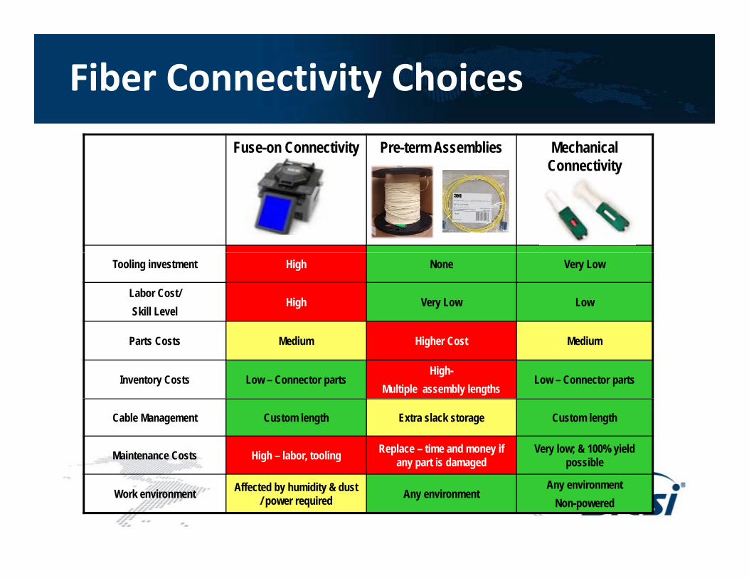
Fiber Connectivity ChoicesFuse-on Connectivity Pre-term Assemblies Mechanical
Connectivity
Tooling investment High None Very Low
Labor Cost/ Skill Level
High Very Low Low
Parts Costs Medium Higher Cost Medium
Inventory Costs Low – Connector parts High-
Multiple assembly lengthsLow – Connector parts
Cable Management Custom length Extra slack storage Custom length
Maintenance Costs High – labor, tooling Replace – time and money if any part is damaged
Very low; & 100% yield possible
Work environment Affected by humidity & dust / power required Any environment
Any environmentNon-powered

Pre-terminated Cable Assemblies
FEATURESV i l th il blo Various lengths available
o Factory terminated connectors without splicing
o Usually include pulling eye ando Usually include pulling eye and protection sock
o Multi-fiber backbone cable
ADVANTAGESo Factory built and testedo Factory test results includedyo No field tools requiredo Minimal training / skillo Efficient installation

Pre-terminated Multi-fiber Backbone Telecom Room/ClosetRack panel, rack- or wall-mount enclosure
Z
• Trunks used for backbonei b lli & i
Equipment RoomRack panel rack or
Zone area enclosure
Floor 1
Floor n MPO Trunks• Saves time by pulling & connecting
multiple fibers at once.• Plug together efficient installation
Use MPO-MPO trunk with
Rack panel, rack- or wall-mount enclosure
g g
Use MPO-MPO trunk with fan-out modules at both ends
Use MPO-SCAPC trunk with fan-out module on only one end
MPO – Multi-fiber Push On Connector

Typical Connector TypesField TerminationField Termination
• SC connector, 2.5mm ceramic ferrule, push/pullLC t 1 25 i f l h/l t h
UPC end face
• LC connector, 1.25mm ceramic ferrule, push/latch– ½ size of SC for greater density
• UPC – Ultra Physical Contact < -55dB reflection APC end face
• APC – Angle Physical Contact < -65dB reflection
Field Termination process by design
• Adhesive Polish
SC / UPC
• No Polish Mechanical Splice-on
• No Polish Fusion Splice-on SC / APCLC / UPC• Cleave and Crimp-on
LC / UPC

Technical Choices of Connector Types
• SC Fusion Splice-On
Factory cleaved fiber
S li t ti l
Yarn and / or cable strain relief
Fi ld bl ith t i d dSplice protection sleeve Field cable with stripped and cleaved fiber
Fusion splice point Strain relief bootPre-polished ferrule and fiber

Technical Choices of Connector Types
• SC Mechanical Crimp - On
M h i l i i l t Fi ld bl ith t i d d
Press button by thumb
Mechanical gripping element Field cable with stripped and cleaved fiber
Press button by thumbto activate splice
No spliceNo adhesive Strain relief boot
Fast field finishNo adhesive
Buffer Clamp

Technical Choices of Connector Types
• SC Mechanical Splice-On
Factory cleaved fiber
M h i l li l t
Yarn and / or cable strain relief
Fi ld bl ith t i d d
Press button by thumb
Mechanical splice element Field cable with stripped and cleaved fiber
Grip cable jacket with screw on, hard
h ll b t
Press button by thumbto activate splice
Mechanical splice point Strain relief bootshell boot
Pre-polished ferrule and fiber Buffer Clamp
Grip aramid fiberin boot threads

Field Termination – Time to Connect

Common POL Configurations – A & B
PASSIVE OPTICAL SPLITTERS IN TELECOM ROOM
– for traditional PC, VoIP
phone, printer
Cat 6 cords
Interconnect solution – Splitters direct to horizontal.
Wall outlet SC/APC
Optional
ONT
ONT
A Optical splitter(s)
Singlemode Fiber Horizontalhierarchical star
cablingTelecom Room (TR)/Closet
printer, WAP, etc.
Any device with
Ethernet
Cross connect option– added patch panel to horizontal
OptionalCross-connect
ONT
ONT
Fiber patchcords
BOptical splitter(s)
g
Ethernet port
Floors 1-nTelecom Enclosure
PASSIVE OPTICAL SPLITTERS IN ZONE AREA
– wallmount, ceiling, or floor enclosure.
Sing
lem
ode
ber B
ackb
one ONT
Optical Network Terminals (ONT) Workgroup Switch
B
Fiber patch panels –OLT to Backbone
Configuration A – Telecom Room StarOptional
S
Fib
Optical Line Terminal (OLT)
Configuration B – Zone Distributors
OLT
OptionalCross-connect
Cross-connect option
Terminal (OLT) Ethernet Aggregation Switch
Main Equip.Room (ER)
MC

In Depth Financial Analysis
Total Upfront Expenditures
• Training is zero for pre-term highest Upfront p gfor fusion
• Inventory is cost f it l hi h i
Upfront Training
On-hand of capital, high in pre-term
• Capital equipment
On-hand Inventory RequirementTotal Capital p q p
highest for fusion
Pre-terminated Fuse-on Mechanical
Total Capital Equipment
Pre terminated Solution #1
Fuse on Connectors Solution #2
Mechanical Connectors Solution #3

In Depth Financial Analysis
Total Installed Cost Comparison per 200' Fiber Assembly
• Pre-term has highest cost of
Assembly
S / t t gmaterials with lowest labor
Scrap/waste cost per dropLabor Total
Bulk Fiber Cable CostField Terminated
d h l
Connector CostPre-terminated Cable Cost
Pre-terminated Solution #1*
Fuse-on Connectors Solution #2
Mechanical Connectors Solution #3

Summary and Resources• Singlemode fibers are now moving into the LAN space for Fiber to the
Desk applications.• The latest Bend-Insensitive fibers provide low loss in tight building spaces.• Connector choices for structured cabling deployment offer easy and fast
installations, in pre-terminated assemblies or easy and fast field , p yterminations similar to RJ45 cabling.
• GPON technology takes advantage of the highest bandwidth over distance of singlemode fiber, and draws from the ease of installation of the latest in g ,fiber connectivity.
• Resources– FOTC – Fiber Optic Tech ConsortiumFOTC Fiber Optic Tech Consortium
• http://fols.tiaonline.org– APOLAN – Association of Passive Optical LAN
• http://www apolanglobal org• http://www.apolanglobal.org