
Fiber Termination Block With MPO Connectors (FTB w/MPO) · connectors on front of the block, and an...
23
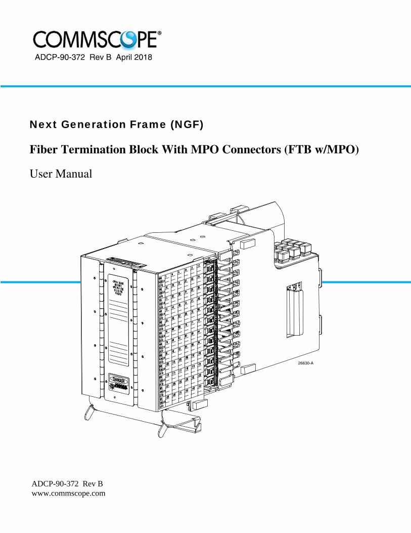
ADCP-90-372 Rev B www.commscope.com ADCP-90-372 Rev B April 2018 26630-A Fiber Termination Block With MPO Connectors (FTB w/MPO) User Manual Next Generation Frame (NGF)
Transcript of Fiber Termination Block With MPO Connectors (FTB w/MPO) · connectors on front of the block, and an...
ADCP-90-372 Rev B www.commscope.com
ADCP-90-372 Rev B April 2018
26630-A
Fiber Termination Block With MPO Connectors (FTB w/MPO)
User Manual
Next Generation Frame (NGF)

ADCP-90-372 • Rev B • April 2018 • Preface
Page ii
COPYRIGHT
© 2018, CommScope Inc.All Rights Reserved
REVISION HISTORY
TRADEMARK INFORMATION
CommScope and CommScope (logo), are trademarks.
Telcordia is a registered trademark of Telcordia Technologies, Inc.
GORE is a registered trademark of W. L. Gore & Associates, Inc.
DISCLAIMER OF LIABILITY
Contents herein are current as of the date of publication. CommScope reserves the right to change the contents without prior notice.In no event shall CommScope be liable for any damages resulting from loss of data, loss of use, or loss of profits andCommScope further disclaims any and all liability for indirect, incidental, special, consequential or other similar damages.This disclaimer of liability applies to all products, publications and services during and after the warranty period.
This publication may be verified at any time online by contacting CommScope Technical Assistance Center using the followingURL: http://www.commscope.com/SupportCenter
ISSUE DATE REASON FOR CHANGE
2 4/2010 Updated to add MPO connector interface.
Rev B April 2018 Updated to CommScope format.

ADCP-90-372 • Rev B • April 2018 • Preface
TABLE OF CONTENTS
Content Page
About This Month . . . . . . . . . . . . . . . . . . . . . . . . . . . . . . . . . . . . . . . . . . . . . . . . . . . . . . . . . . . . . . . . . . . . . . . . . . . . v
Related Publications . . . . . . . . . . . . . . . . . . . . . . . . . . . . . . . . . . . . . . . . . . . . . . . . . . . . . . . . . . . . . . . . . . . . . . . . . . v
Admonishments . . . . . . . . . . . . . . . . . . . . . . . . . . . . . . . . . . . . . . . . . . . . . . . . . . . . . . . . . . . . . . . . . . . . . . . . . . . . .vi
General Safety Precautions . . . . . . . . . . . . . . . . . . . . . . . . . . . . . . . . . . . . . . . . . . . . . . . . . . . . . . . . . . . . . . . . . . . . .vi
List of Acronyms and Abbreviations . . . . . . . . . . . . . . . . . . . . . . . . . . . . . . . . . . . . . . . . . . . . . . . . . . . . . . . . . . . . . . . .vi
1 PRODUCT DESCRIPTION . . . . . . . . . . . . . . . . . . . . . . . . . . . . . . . . . . . . . . . . . . . . . . . . . . . . . . . . . . . . . . . . . . 1
1.1 General Description . . . . . . . . . . . . . . . . . . . . . . . . . . . . . . . . . . . . . . . . . . . . . . . . . . . . . . . . . . . . . . . . 1
1.2 Product Function . . . . . . . . . . . . . . . . . . . . . . . . . . . . . . . . . . . . . . . . . . . . . . . . . . . . . . . . . . . . . . . . . . 2
1.3 Main Components . . . . . . . . . . . . . . . . . . . . . . . . . . . . . . . . . . . . . . . . . . . . . . . . . . . . . . . . . . . . . . . . . 2
1.4 Options That Affect Installation . . . . . . . . . . . . . . . . . . . . . . . . . . . . . . . . . . . . . . . . . . . . . . . . . . . . . . . . 3
1.5 Accessories . . . . . . . . . . . . . . . . . . . . . . . . . . . . . . . . . . . . . . . . . . . . . . . . . . . . . . . . . . . . . . . . . . . . . 4
1.6 Applications . . . . . . . . . . . . . . . . . . . . . . . . . . . . . . . . . . . . . . . . . . . . . . . . . . . . . . . . . . . . . . . . . . . . . 4
1.6.1 Interconnect Application. . . . . . . . . . . . . . . . . . . . . . . . . . . . . . . . . . . . . . . . . . . . . . . . . . . . . . 4
1.6.2 Cross-Connect Application . . . . . . . . . . . . . . . . . . . . . . . . . . . . . . . . . . . . . . . . . . . . . . . . . . . . 4
1.7 Specifications . . . . . . . . . . . . . . . . . . . . . . . . . . . . . . . . . . . . . . . . . . . . . . . . . . . . . . . . . . . . . . . . . . . . 5
2 UNPACKING AND INSPECTING THE PRODUCT . . . . . . . . . . . . . . . . . . . . . . . . . . . . . . . . . . . . . . . . . . . . . . . . . . . . 5
3 MOUNTING THE FTB ON THE RACK . . . . . . . . . . . . . . . . . . . . . . . . . . . . . . . . . . . . . . . . . . . . . . . . . . . . . . . . . . . 6
4 MPO TRUNK CABLE INSTALLATION . . . . . . . . . . . . . . . . . . . . . . . . . . . . . . . . . . . . . . . . . . . . . . . . . . . . . . . . . . . 7
4.1 Preparing Cable for Installation. . . . . . . . . . . . . . . . . . . . . . . . . . . . . . . . . . . . . . . . . . . . . . . . . . . . . . . . 7
4.2 Routing and Securing the Cable. . . . . . . . . . . . . . . . . . . . . . . . . . . . . . . . . . . . . . . . . . . . . . . . . . . . . . . . 7
5 12-STRAND MPO CABLE INSTALLATION. . . . . . . . . . . . . . . . . . . . . . . . . . . . . . . . . . . . . . . . . . . . . . . . . . . . . . . 10
5.1 Routing and Securing the Cable. . . . . . . . . . . . . . . . . . . . . . . . . . . . . . . . . . . . . . . . . . . . . . . . . . . . . . . 10
6 PATCH CORD INSTALLATION . . . . . . . . . . . . . . . . . . . . . . . . . . . . . . . . . . . . . . . . . . . . . . . . . . . . . . . . . . . . . . 13
7 CUSTOMER INFORMATION AND ASSISTANCE . . . . . . . . . . . . . . . . . . . . . . . . . . . . . . . . . . . . . . . . . . . . . . . . . . . 16
Page iii© 2018, CommScope, Inc.

ADCP-90-372 • Rev B • April 2018 • Preface
TABLE OF CONTENTS
Content Page
Blank Page
Page iv© 2018, CommScope, Inc.

ADCP-90-372 • Rev B • April 2018 • Preface
ABOUT THIS MONTH
This user manual provides the following information:
• A description of Fiber Termination Block with MPO Connectors (FTB w/MPO).
• Procedures for installing an FTB w/MPO on a Next Generation Frame (NGF);
• Procedures for routing and connecting an MPO trunk cable to the FTB w/MPO;
• Guidelines for connecting patch cords to the FTB w/MPO.
The procedures for installing the various NGF racks and accessories are provided in otherCommScope publications (see “Related Publications,” below).
RELATED PUBLICATIONS
Listed below are related manuals and their publication numbers. Copies of these publications canbe ordered by contacting the CommScope Technical Assistance Center using the URL:http://www.commscope.com/SupportCenter
NGF Fiber Main Distributing Frame User Manual 90-273Provides a complete description of the FMDF and procedures for installing the FMDF rack, the FTB, and the FCB.
NGF Slim Rack Installation Guide 90-274Provides a complete description of the FMDF and procedures for installing the FMDF rack, the FTB, and the FCB.
NGF Fiber Optic Terminal Storage Bay User Manual 90-270Provides instructions for installing the FOTSB with the FMDF rack.
Fiber Main Distribution Frame (FMDF)Interconnect and Cross-Connect Patch Cord Routing Guide 90-240Provides instructions for installing and routing patch cords.
MPO Assembly Field Testing and Repair Instructions 90-378Provides instructions for testing, repairing, and cleaning MPO connectors.
Optical Fiber Connector Wet and Dry Cleaning Instructions 90-159Provides instructions for cleaning optical connectors.
Multifiber-Push On (MPO) Assembly Connector Cleaning Instructions 90-160Provides instructions for cleaning MPO assembly connectors.
Title/Description ADCP Number
Page v© 2018, CommScope, Inc.

ADCP-90-372 • Rev B • April 2018 • Preface
ADMONISHMENTS
Important safety admonishments are used throughout this manual to warn of possible hazards topersons or equipment. An admonishment identifies a possible hazard and then explains whatmay happen if the hazard is not avoided. The admonishments — in the form of Dangers,Warnings, and Cautions — must be followed at all times. These warnings are flagged by use ofthe triangular alert icon (seen below), and are listed in descending order of severity of injury ordamage and likelihood of occurrence.
GENERAL SAFETY PRECAUTIONS
LIST OF ACRONYMS AND ABBREVIATIONS
The following acronyms are used in this manual:
FMDF Fiber Main Distributing FrameFTB Fiber Termination Block
FTB w/MPO Fiber Termination Block With MPO ConnectorsMPO Multifiber Push-on ConnectorNGF Next Generation Frame
Danger: Danger is used to indicate the presence of a hazard that will cause severe personalinjury, death, or substantial property damage if the hazard is not avoided.
Warning: Warning is used to indicate the presence of a hazard that can cause severe personalinjury, death, or substantial property damage if the hazard is not avoided.
Caution: Caution is used to indicate the presence of a hazard that will or can cause minorpersonal injury or property damage if the hazard is not avoided.
Danger: Infrared radiation is invisible and can seriously damage the retina of the eye. Do notlook into the ends of any optical fiber. Do not look directly into the optical adapters of theadapter packs. Exposure to invisible laser radiation may result. An optical power meter shouldbe used to verify active fibers. A protective cap or hood MUST be immediately placed over anyradiating adapter or optical fiber connector to avoid the potential of dangerous amounts ofradiation exposure. This practice also prevents dirt particles from entering the adapter orconnector.
Page vi© 2018, CommScope, Inc..

ADCP-90-372 • Rev B • April 2018
1 PRODUCT DESCRIPTION
This section describes the CommScope Fiber Termination Block with MPO Connectors (FTBw/MPO). The FTB w/MPO is available with 96, 144, or 192 terminations per block.
1.1 General Description
The FTB w/MPO is used on a NGF rack to provide a point for terminating MPO trunk cables.The FTB separates out the multiple circuits within each MPO connector into its componentindividual circuits. The circuits are terminated to factory-installed pigtails that are routed withinthe FTB to individual connectors in sliding adapter packs. Figure 1 shows the FTB exploded outfrom an NGF frame.
MPO trunk cables terminate at the rear of the FTB where the MPO connectors mounted in theblock are accessed. Cross-connect or interconnect patch cords terminate at the front of the FTBwhere the sliding adapter packs are accessed. The NGF rack, on which the FTB is mounted,provides physical support and cable management.
The FTB w/MPO has a left or right orientation for installation on either the left or right side ofthe NGF rack (as viewed from the front).
Figure 1. FTB Block With MPO Connectors Exploded Out From a NGF Frame
26631-A
Page 1© 2018, CommScope, Inc.

ADCP-90-372 • Rev B • April 2018
1.2 Product Function
An MPO trunk cable contains multiple fibers terminated at a single connector. The FTBseparates out the multiple circuits within each MPO connector into its component individualcircuits. The individual circuits are routed through pigtails to individual connectors on slidingadapter packs. By sliding out an adapter pack and connecting an interconnect or cross-connectpatch cord, a technician easily routes an individual circuit to a local device. In a reversedirection, the FTB can be used to consolidate 12 individual circuits into a single MPO cable forrouting within a facility or to a network element. Figure 2 is a schematic of product function.
Figure 2. FTB w/MPO Product Function
1.3 Main Components
An FTB w/MPO block consists of a sheet metal chassis with physical features providing formounting of MPO connectors on the back of the chassis, mounting of sliding adapter packs onthe front, and placement of factory-installed internal pigtails between the MPO connectors andsliding adapters. The 96-position chassis accepts sliding adapter packs with four adapters each.The adapters are arranged in twelve rows, each with two adapter packs (12x2x4). The 144-position chassis accepts sliding adapter packs with six adapters each (12 rows of 2x6). The 192-position chassis accepts sliding adapter packs with eight adapters each (12 rows of 2x8). Theadapter packs are available with SC and LC ultra-polish adapters. Figure 3 shows the 144position chassis.
The FTB chassis has a removable side cover and two hinged front covers. Removing the sidecover provides access to the rear cable management area where the connectors used forterminating MPO trunk cables are located. The rear cable management area also has an upperradius limiter and other features designed for securing and routing a MPO trunk cable.
MULTIPLE CIRCUITSWITHIN ONE CABLE
MPOCONNECTOR
INDIVIDUALCIRCUITS
IN PIGTAILS
ADAPTERPACKS INTERCONNECT
OR CROSS-CONNECTPATCH CORD
INDIVIDUALCIRCUIT
INDIVIDUALDEVICE
22676-A
Page 2© 2018, CommScope, Inc.

ADCP-90-372 • Rev B • April 2018
Opening the FTB front covers provides access to the adapter packs (by sliding them out) and tothe front radius limiters which facilitate the routing of interconnect or cross-connect patchcords. The front covers also include designation labels to identify the optical circuits.
Figure 3. Fiber Termination Block With MPO Connectors(144-Position Chassis Shown)
1.4 Options That Affect Installation
The following FTB ordering options may affect the installation process:
• The FTB may be ordered with a left or right orientation. The left-orientation FTB installson the left side of the frame (when facing the front of the frame); the right-orientation FTBinstalls on the right side of the frame.
• The FTB may be ordered any of several different types of internal pigtails. Included are50/125 um laser optimized to 300 m, 50/125 um. 62.5/125 um, and singlemode.
• The FTB may be ordered any of several different types of connectors. For a complete list,refer to Table 1 on Page 5.
SLIDINGADAPTER
PACK
LOWERRADIUSLIMITER
FRONTRADIUS
LIMITERS
UPPERRADIUSLIMITER
23885-A
HINGEDFRONT
COVERS
Page 3© 2018, CommScope, Inc.

ADCP-90-372 • Rev B • April 2018
1.5 Accessories
The following accessories are available for use with the FTB:
• Patch Cords—Are available with specified connectors in standard lengths of 6.0, 7.0, 8.0,9.0, 10.0, and 12.0 meters.
• Connector Cleaning Kit—Provides all the materials required to clean fiber opticconnectors and adapters. Two types are required: a ferrule mote kit for the adapterconnectors on front of the block, and an MPO kit for the MPO connectors on back.
1.6 Applications
The FTB may be used to support either interconnect or cross-connect frame applications. Bothare described below.
1.6.1 Interconnect Application
In an interconnect application, only MPO trunk cables are terminated at the rear of the frame.Network elements are connected directly to the trunk cables using interconnect patch cords. Theexcess patch cord slack is stored in the slack storage area on the front of the frame. Figure 4shows a typical interconnect application using the FMDF. An interconnect application uses theentire frame for terminating trunk cables. An overhead or underfloor fiber raceway system suchas the FiberGuide system must be used for routing the interconnect patch cords to the frame.
Figure 4. Typical Interconnect Application
1.6.2 Cross-Connect Application
In a cross-connect application, both network elements and MPO trunk cables are terminated atthe rear of the frame. A network element may be connected to a trunk cable, a network elementmay be connected to another network element, or a trunk cable may be connected to anothertrunk cable, using a cross-connect patch cord.
MPOTRUNKCABLE
NETWORK ELEMENTPATCH CORD
ADAPTER
PIGTAIL
INTERCONNECT WITH MPO TRUNKCABLE TERMINATED AT FTB
22707-C
FTB
FRONT
Page 4© 2018, CommScope, Inc.

ADCP-90-372 • Rev B • April 2018
The excess patch cord slack is stored in the slack area on the front of the frame. Figure 5 showsa typical cross-connect application using the FMDF.
Figure 5. Typical Cross-connect Application
1.7 Specifications
2 UNPACKING AND INSPECTING THE PRODUCT
Use the following procedure to unpack and inspect the FTB w/MPO:
1. Inspect the exterior of the shipping container for evidence of rough handling that may havedamaged the contents of the container.
2. Unpack the FTB and inspect for possible damage.
Table 1. FTB Specifications
PARAMETER SPECIFICATION REMARKSNumber of Terminations 96, 144, or 192
Connector types singlemode SC ultra polish; singlemode SC angled polish; multimode SC; multimode SC aqua (for 10 Gig applications)
96 or 144 only
singlemode LC ultra polish, singlemode LC angled polish; multimode LC; multimode LC aqua (for 10 Gig applica-tions)
144 or 192 only
Operating Temperature –40° C to 65° C (–40° F to149° F)
Storage Temperature –55° C to 85° C (–85° F to185° F)
Relative Humidity
Operating Up to 80% No condensation
Storage Up to 95% No condensation
MPOTRUNKCABLE
NETWORKELEMENT
PATCH CORD
ADAPTERCROSS-CONNECT WITH MPO TRUNK CABLETERMINATED AT FTB AND NETWORK ELEMENT
PATCH CORDS TERMINATED AT FTB 22708-C
CROSS-CONNECTPATCH CORD
PIGTAIL
FTB
FTB
FRONT
Page 5© 2018, CommScope, Inc.

ADCP-90-372 • Rev B • April 2018
3. If damage is detected or if parts are missing, file a claim with the commercial carrier andthen notify CommScope Customer Service (http://www.commscope.com/SupportCenter).Save damaged carton for inspection by carrier.
4. Even if no damage is evident, save the shipping container in case the equipment requiresshipment at a future date.
3 MOUNTING THE FTB ON THE RACK
Use the following procedure to mount the FTB on the NGF rack (see Figure 6):
1. Unpack the FTB.
Figure 6. FTB Installation on Rack
2. Locate the designated mounting position for the FTB. In a new rack installation, the rackmay be populated by starting at the bottom and working toward the top or by starting at thetop and working toward the bottom. Left-oriented FTBs mount only on the left side of therack and right-oriented FTBs mount only on the right side of the rack.
Note: If installing a 144 position FTB with SC or LC adapters on a 30-inch standard frame(NGFB-MDF7A100-30 or NGF-MDF7A100-30), remove the long brackets on the frameand replace them with the short brackets provided with the FTB per the installationinstructions provided. If installing a 144 position FTB with SC or LC adapters on a 30-inch short bracket frame (NGFB-MDF7A144-30), discard the separate short brackets;they are not needed.
26631-A
Page 6© 2018, CommScope, Inc.

ADCP-90-372 • Rev B • April 2018
3. Slide the FTB onto the appropriate mounting bracket at the front of the rack as shown inFigure 6.
4. Secure the FTB to the rack mounting bracket using the two #12-24 screws provided.
5. Repeat steps 1–4 for each FTB.
4 MPO TRUNK CABLE INSTALLATION
This involves first preparing the cable and then routing the cable and securing it on the rack. Fordetails, refer to the topics below.
4.1 Preparing Cable for Installation
Before being installed, the MPO trunk cable must be broken out using the breakout dimensionsshown in Figure 7.
Figure 7. MTO Trunk Cable Breakout Dimensions
4.2 Routing and Securing the Cable
MPO trunk cables maybe routed into the FTB from either above or below the rack. Use thefollowing procedure for routing and securing the MPO cable (see Figure 8 and Figure 9).
Caution: Inspect each cable and clean the MPO connectors before connecting the cable. Forinstructions, refer to ADCP-90-379.
13.5 IN.(34.3 CM)
ONE STRAND(12 CIRCUITS)
MPO TRUNK(12 STRANDS) FURCATION
22714-A
Page 7© 2018, CommScope, Inc.

ADCP-90-372 • Rev B • April 2018
1. Route the MPO cable from above or below the rack corresponding to the arrangementshown in Figure 8 and Figure 9.
2. Locate the cable tying position on the cable tie brackets on the side of the rack. Usingcable lacing, tie down the cable. Position all furcations at the rear of the tie bar as shown.
3. Connect the MPO connectors as shown.
4. Repeat this procedure for each cable being installed.
Figure 8. MPO Trunk Cable Routing Into FTB (Rear View)
Note: For the top FTB in a top entry application, secure the cable to the ladder rackoverhead, as indicated in Figure 10.
FTB
FTB
RACK
TIE OFF ONTIE NEXT TO
BLOCK
MPOTRUNK
13.5-INCHSUB-UNIT
FURCATION
FTB
FTB
RACK
TIE OFF ONTIE ONE BLOCK
ABOVE
FURCATION
MPOTRUNK
13.5-INCHSUB-UNIT
BOTTOM ENTRY TOP ENTRY23870-A
Page 8© 2018, CommScope, Inc.

ADCP-90-372 • Rev B • April 2018
Figure 9. Routing MPO Trunk Cables on NGF Rack (Side View)
1 2 3 4 5 6
BOTTOM ENTRY 22643-A
FOR BOTTOM ENTRY, PLACEAND SECURE CABLES AS SHOWN.FRAME MAY BE POPULATEDFROM THE BOTTOM OR TOP.
MPO12-STRANDS
ALTERNATECUT-OUT FOR
CABLE TIE
FTB MOUNTINGBRACKET
CABLETIE BAR
USE WAX STRINGOR CABLE TIES
(PER LOCAL PRACTICE)TO SECURE CABLE TOCABLE TIE BRACKET
MPO 6
MPO 5
MPO 4
MPO 3
MPO 2
MPO 1
MPO 6
MPO 5
MPO 4
MPO 3
MPO 2
MPO 1
6 5 4 3 2 1
TOP ENTRYFOR TOP ENTRY, PLACE AND SECURE CABLES AS SHOWN.FRAME MAY BE POPULATEDFROM THE BOTTOM OR TOP.
MPOTRUNKCABLE
LADDERRACK
NOTE:POSITION ALLFURCATIONSAT REAR OFTIE BAR.
Page 9© 2018, CommScope, Inc.

ADCP-90-372 • Rev B • April 2018
Figure 10. Top Entry MPO Cable, Top FTB
5 12-STRAND MPO CABLE INSTALLATION
Routing and installation of 12-strand MPO cables is similar to routing and installation of MPOtrunk cables except no cable breakout is required.
5.1 Routing and Securing the Cable
MPO 12-strand cables maybe routed into the FTB from either above or below the rack. Use thefollowing procedure.
1. Measure out a length 13.5 inches (34.3 cm) from the connector and mark a tie-down pointas shown in Figure 11. This is the point at which the cable will be tied to the rack.
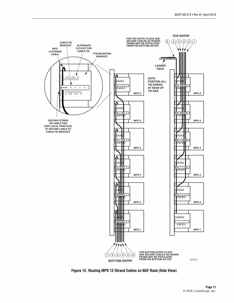
2. Route the MPO cable from above or below the rack as shown in Figure 12.
Figure 11. Marking Out Tie-Down Point
Caution: Inspect each cable and clean the MPO connectors before connecting the cable. Forinstructions, refer to ADCP-90-378.
SECURE CABLESTO LADDER RACK
26632-A
MPOCONNECTOR
TIE-OFFPOINT
13.5 IN.(34.3 CM)
22721-A
Page 10© 2018, CommScope, Inc.
ADCP-90-372 • Rev B • April 2018
Figure 12. Routing MPO 12-Strand Cables on NGF Rack (Side View)
1 2 3 4 5 6
BOTTOM ENTRY 22722-A
FOR BOTTOM ENTRY, PLACEAND SECURE CABLES AS SHOWN.FRAME MAY BE POPULATEDFROM THE BOTTOM OR TOP.
MPO12-STRAND
CABLE
ALTERNATECUT-OUT FOR
CABLE TIE FTB MOUNTING
BRACKET
CABLE TIEBRACKET
USE WAX STRINGOR CABLE TIES
(PER LOCAL PRACTICE)TO SECURE CABLE TOCABLE TIE BRACKET
MPO 6
MPO 5
MPO 4
MPO 3
MPO 2
MPO 1
MPO 6
MPO 5
MPO 4
MPO 3
MPO 2
MPO 1
6 5 4 3 2 1
TOP ENTRYFOR TOP ENTRY, PLACE AND SECURE CABLES AS SHOWN.FRAME MAY BE POPULATEDFROM THE BOTTOM OR TOP.
LADDERRACK
NOTE:POSITION ALLTIE DOWNSAT REAR OFTIE BAR.
Page 11© 2018, CommScope, Inc.

ADCP-90-372 • Rev B • April 2018
3. Locate the cable tying position on the cable tie brackets on the side of the rack. Usingcable lacing, tie down the cable at the tie-down point determined in step 1 above. Positionall tie-downs at the rear of the tie bar as shown.
4. Connect the MPO connector as shown.
Figure 13. MPO Trunk Cable Routing Into FTB (Rear View)
Note: In a top entry application, tie off the cable on the tie off one block above the blockwhere the cable will be connected, as shown in Figure 13. In a bottom entry application,tie off on the cable on the tie off next to the block where the cable will be connected, asalso show in Figure 13.
Note: For the top FTB in a top entry application, secure the cable to the ladder rackoverhead, as shown in Figure 10 on Page 10.
MPO12-STRAND
CABLE
MPO12-STRAND
CABLE
FTB
FTB
RACK
TIE OFF ONTIE NEXT TO
BLOCK
13.5-INCHSUB-UNIT
FTB
FTB
RACK
TIE OFF ONTIE ONE BLOCK
ABOVE
13.5-INCHSUB-UNIT
BOTTOM ENTRY TOP ENTRY23871-A
Page 12© 2018, CommScope, Inc.

ADCP-90-372 • Rev B • April 2018
6 PATCH CORD INSTALLATION
Patch cords are installed on the front of the rack to route individual circuits from the FTB toanother FTB (cross-connect) or directly to local equipment (interconnect).
1. To ready the FTB for connecting a patch cord, open the door and slide out the desiredadapter pack as shown in Figure 14.
Figure 14. Sliding Out an Adapter Pack
23873-A
DOOR
ADAPTERPACKS
Page 13© 2018, CommScope, Inc.

ADCP-90-372 • Rev B • April 2018
2. Remove the dust cap from the desired adapter and connect the patch cord as shown inFigure 15.
Figure 15. Connecting the Patch Cord
3. Route the patch cord around the radius limiters, into the distribution trough, and in eitherof the two directions as shown in Figure 16.
Figure 16. Routing the Patch Cord in the Distribution Trough
Note: For cleaning instructions, refer to ADCP-90-139.
23874-A
DUSTCAP
23875-A
HORIZONTALREAR TROUGH
DISTRIBUTIONTROUGH
TO FTB INSAME FRAME
TO FTB INDIFFERENT
FRAME WITHINSAME LINEUP
RADIUSLIMITERS
Page 14© 2018, CommScope, Inc.

ADCP-90-372 • Rev B • April 2018
4. In all cases. when routing and storing patch cords on the front of the frame, observe theguidelines indicated in Figure 17.
Figure 17. Patch Cord Routing on Front of Rack
5. For specific routing instructions, refer to the laminated cards handing on the rack (ADCP-90-240, Fiber Main Distribution Frame (FMDF) Interconnect and Cross-Connect PatchCord Routing Guide).
DO NOT WRAP PATCHCORD MULTIPLE TIMESAROUND SAME SPOOL
DO NOT WEAVEPATCH CORD
AROUND SPOOLS
17355-A
FTB #1
FTB #2
CORRECT ROUTINGUNDER EDGE PROTECTOR
STORAGEPANEL
CROSS-CONNECTPATCH CORD
EDGE PROTECTOR
INCORRECT ROUTING
CORRECT ROUTINGWITHIN STORAGE PANEL
Page 15© 2018, CommScope, Inc.

ADCP-90-372 • Rev B • April 2018
7 CUSTOMER INFORMATION AND ASSISTANCE
Visit our website or contact your local CommScope representative for more information.
• To find out more about CommScope® products, visit us on the web atwww.commscope.com
• For technical assistance, customer service, or to report any missing/damaged parts, visit usat http://www.commscope.com/SupportCenter
Page 16

ADCP-90-372 • Rev B • April 2018
Page 17© 2018, CommScope, Inc.