Fiber Optics Sensors Standards Report -...
30
Fiber Optics Sensors Standards Report IEEE-SA Industry Connections White Paper IEEE | 3 Park Avenue | New York, NY 10016-5997 | USA Authors: David Krohn Chairman, IEEE Fiber Optics Standards Activity (Light Wave Venture LLC) Alexis Méndez Vice Chairman, IEEE Fiber Optics Standards Activity (MCH Engineering LLC)
Transcript of Fiber Optics Sensors Standards Report -...
Copyright © 2017 IEEE. All rights reserved.
Fiber Optics Sensors Standards Report
IEEE-SA Industry Connections White Paper
IEEE | 3 Park Avenue | New York, NY 10016-5997 | USA
Authors:
David Krohn Chairman, IEEE Fiber
Optics Standards Activity (Light Wave Venture LLC)
Alexis Méndez Vice Chairman, IEEE Fiber Optics Standards Activity
(MCH Engineering LLC)
i
Copyright © 2017 IEEE. All rights reserved.
Fiber Optics Sensors Standards Report
Authors:
David Krohn Chairman, IEEE Fiber
Optics Standards Activity (Light Wave Venture LLC)
Alexis Méndez
Vice Chairman, IEEE Fiber Optics Standards Activity
(MCH Engineering LLC)
ii
Copyright © 2017 IEEE. All rights reserved.
Trademarks and Disclaimers IEEE believes the information in this publication is accurate as of its publication date; such information is subject to change without notice. IEEE is not responsible for any inadvertent errors.
The Institute of Electrical and Electronics Engineers, Inc. 3 Park Avenue, New York, NY 10016-5997, USA Copyright © 2017 by The Institute of Electrical and Electronics Engineers, Inc. All rights reserved. Published Month 20xx. Printed in the United States of America. IEEE is a registered trademark in the U. S. Patent & Trademark Office, owned by The Institute of Electrical and Electronics Engineers, Incorporated. PDF: ISBN 978-0-7381-xxxx-x STDVxxxxx Print: ISBN 978-0-7381-xxxx-x STDPDVxxxxx IEEE prohibits discrimination, harassment, and bullying. For more information, visit http://www.ieee.org/web/aboutus/whatis/policies/p9-26.html. No part of this publication may be reproduced in any form, in an electronic retrieval system, or otherwise, without the prior written permission of the publisher. To order IEEE Press Publications, call 1-800-678-IEEE. Find IEEE standards and standards-related product listings at: http://standards.ieee.org
iii
Copyright © 20xx IEEE. All rights reserved.
Notice and Disclaimer of Liability Concerning the Use of IEEE-SA Industry Connections Documents
This IEEE Standards Association (“IEEE-SA”) Industry Connections publication (“Work”) is not a consensus standard document. Specifically, this document is NOT AN IEEE STANDARD. Information contained in this Work has been created by, or obtained from, sources believed to be reliable, and reviewed by members of the IEEE-SA Industry Connections activity that produced this Work. IEEE and the IEEE-SA Industry Connections activity members expressly disclaim all warranties (express, implied, and statutory) related to this Work, including, but not limited to, the warranties of: merchantability; fitness for a particular purpose; non-infringement; quality, accuracy, effectiveness, currency, or completeness of the Work or content within the Work. In addition, IEEE and the IEEE-SA Industry Connections activity members disclaim any and all conditions relating to: results; and workmanlike effort. This IEEE-SA Industry Connections document is supplied “AS IS” and “WITH ALL FAULTS.” Although the IEEE-SA Industry Connections activity members who have created this Work believe that the information and guidance given in this Work serve as an enhancement to users, all persons must rely upon their own skill and judgment when making use of it. IN NO EVENT SHALL IEEE OR IEEE-SA INDUSTRY CONNECTIONS ACTIVITY MEMBERS BE LIABLE FOR ANY ERRORS OR OMISSIONS OR DIRECT, INDIRECT, INCIDENTAL, SPECIAL, EXEMPLARY, OR CONSEQUENTIAL DAMAGES (INCLUDING, BUT NOT LIMITED TO: PROCUREMENT OF SUBSTITUTE GOODS OR SERVICES; LOSS OF USE, DATA, OR PROFITS; OR BUSINESS INTERRUPTION) HOWEVER CAUSED AND ON ANY THEORY OF LIABILITY, WHETHER IN CONTRACT, STRICT LIABILITY, OR TORT (INCLUDING NEGLIGENCE OR OTHERWISE) ARISING IN ANY WAY OUT OF THE USE OF THIS WORK, EVEN IF ADVISED OF THE POSSIBILITY OF SUCH DAMAGE AND REGARDLESS OF WHETHER SUCH DAMAGE WAS FORESEEABLE. Further, information contained in this Work may be protected by intellectual property rights held by third parties or organizations, and the use of this information may require the user to negotiate with any such rights holders in order to legally acquire the rights to do so, and such rights holders may refuse to grant such rights. Attention is also called to the possibility that implementation of any or all of this Work may require use of subject matter covered by patent rights. By publication of this Work, no position is taken by the IEEE with respect to the existence or validity of any patent rights in connection therewith. The IEEE is not responsible for identifying patent rights for which a license may be required, or for conducting inquiries into the legal validity or scope of patents claims. Users are expressly advised that determination of the validity of any patent rights, and the risk of infringement of such rights, is entirely their own responsibility. No commitment to grant licenses under patent rights on a reasonable or non-discriminatory basis has been sought or received from any rights holder. The policies and procedures under which this document was created can be viewed at http://standards.ieee.org/about/sasb/iccom/. This Work is published with the understanding that IEEE and the IEEE-SA Industry Connections activity members are supplying information through this Work, not attempting to render engineering or other professional services. If such services are required, the assistance of an appropriate professional should be sought. IEEE is not responsible for the statements and opinions advanced in this Work.
iv
Copyright © 2017 IEEE. All rights reserved.
CONTENTS
OBJECTIVE..................................................................................................... 1
STANDARDS ORGANIZATIONS ...................................................................... 1
LIST OF EXISTING FIBER OPTIC SENSOR STANDARDS ..................................... 2
Table 1: List of standards documents ....................................................................................... 2
OVERVIEW OF CURRENT STANDARDIZATION STATUS ................................... 3
Figure 1: Structure of the standards related to fiber-optic strain sensors ................................... 5
Figure 2: Structure of the standards related to fiber-optic temperature sensors ........................ 5
GAP ANALYSIS .............................................................................................. 6
SUMMARY OF ACTIVITIES AND RECOMMENDATIONS ................................... 7
REFERENCES .................................................................................................. 8
APPENDIX I ................................................................................................... 9
APPENDIX II ................................................................................................ 24
1
Copyright © 20xx IEEE. All rights reserved.
Fiber Optics Sensors Standards Report
Objective
The objective of the IEEE activity is to make a contribution on expanding fiber optic sensor standards. After reviewing the broad range of fiber optic sensor standards activities from IEC, ASTM, ISHMII, SEAFOM, SAE, and the Wolfgang Habel paper (Results in Standardization of FOS to Support the Use of SHM Systems) it is clear that there has been a lot of progress. However, the multiplicity of standards activities from different organizations makes tracking standards difficult. For standards to be effective, they must be available for developers, suppliers and users to facilitate broad use of optic fiber sensor technology. This effort is to support the IEEE activity to track the results of the various groups and provide a comprehensive list of references to the specific standards activities. This activity will help focus on gaps in standards, which will be the basis for advancing standards efforts.
Standards Organizations
The organizations listed next have been active in developing standards for fiber optic sensors. There are a total of 15 organizations involved. While there has been cooperation between various standards groups, other groups have focused on specific markets and applications. The result has created a circuitous path to grasping and understanding the full range of fiber optic sensor standards.
ARINC: Aeronautical Radio Incorporated ASTM: American Society of Testing Materials EIA: Electronic Industries Alliance ENERGISTICS: Formerly Petrotechnical Open Software Corporation (POSC) IEC: International Electrotechnical Commission IEEE: Institute of Electrical and Electronics Engineers ISA: Instrument Society of America ISHMII: International Society for Structural Health Monitoring of Intelligent
Infrastructure ISO: International Organization for Standardization RILEM: International Union of Laboratories and Experts in Construction Materials,
Systems and Structures SAE: Society of Automotive Engineers SIIS: Subsea Instrumentation Interface Standardization SEAFOM: Subsea Fiber Optic Monitoring Group TIA: Telecommunications Industry Association VDI: The Association of German Engineers
2
Copyright © 2017 IEEE. All rights reserved.
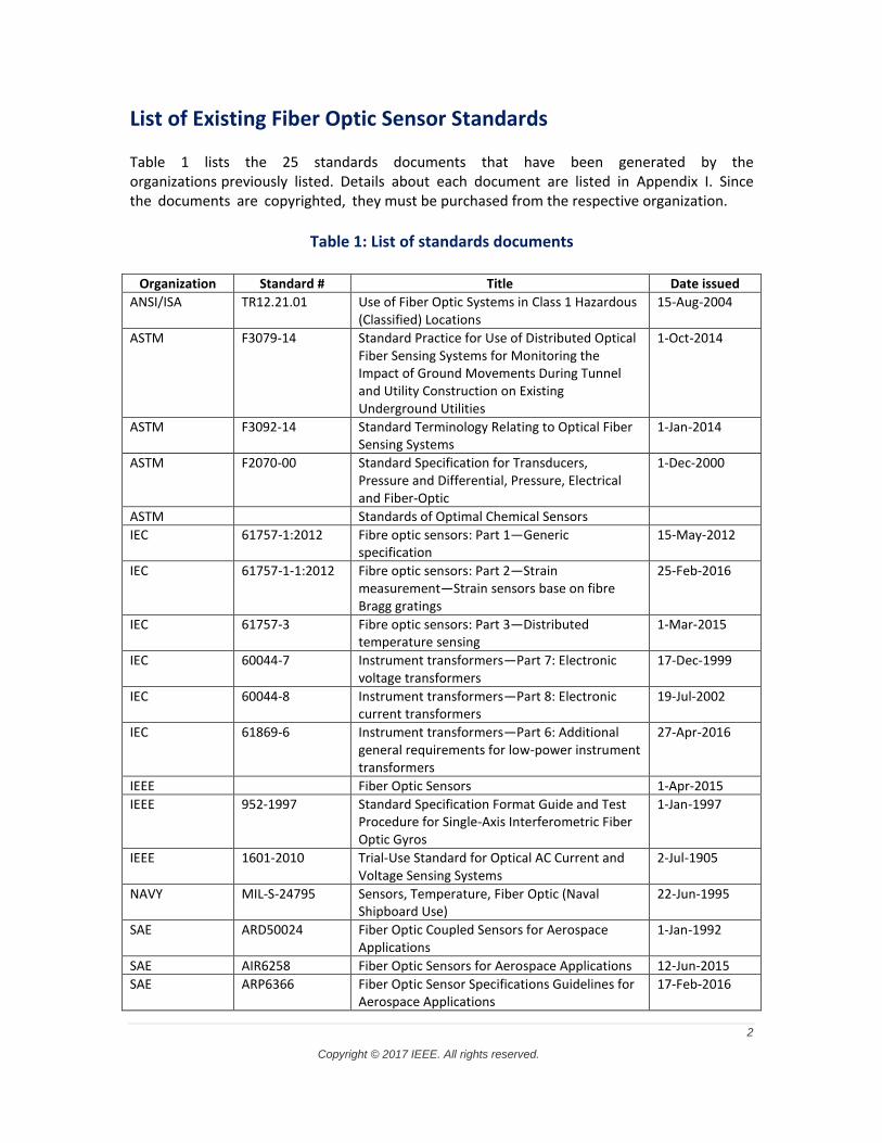
List of Existing Fiber Optic Sensor Standards
Table 1 lists the 25 standards documents that have been generated by the organizations previously listed. Details about each document are listed in Appendix I. Since the documents are copyrighted, they must be purchased from the respective organization.
Table 1: List of standards documents
Organization Standard # Title Date issued
ANSI/ISA TR12.21.01 Use of Fiber Optic Systems in Class 1 Hazardous (Classified) Locations
15-Aug-2004
ASTM F3079-14 Standard Practice for Use of Distributed Optical Fiber Sensing Systems for Monitoring the Impact of Ground Movements During Tunnel and Utility Construction on Existing Underground Utilities
1-Oct-2014
ASTM F3092-14 Standard Terminology Relating to Optical Fiber Sensing Systems
1-Jan-2014
ASTM F2070-00 Standard Specification for Transducers, Pressure and Differential, Pressure, Electrical and Fiber-Optic
1-Dec-2000
ASTM Standards of Optimal Chemical Sensors
IEC 61757-1:2012 Fibre optic sensors: Part 1—Generic specification
15-May-2012
IEC 61757-1-1:2012 Fibre optic sensors: Part 2—Strain measurement—Strain sensors base on fibre Bragg gratings
25-Feb-2016
IEC 61757-3 Fibre optic sensors: Part 3—Distributed temperature sensing
1-Mar-2015
IEC 60044-7 Instrument transformers—Part 7: Electronic voltage transformers
17-Dec-1999
IEC 60044-8 Instrument transformers—Part 8: Electronic current transformers
19-Jul-2002
IEC 61869-6 Instrument transformers—Part 6: Additional general requirements for low-power instrument transformers
27-Apr-2016
IEEE Fiber Optic Sensors 1-Apr-2015
IEEE 952-1997 Standard Specification Format Guide and Test Procedure for Single-Axis Interferometric Fiber Optic Gyros
1-Jan-1997
IEEE 1601-2010 Trial-Use Standard for Optical AC Current and Voltage Sensing Systems
2-Jul-1905
NAVY MIL-S-24795 Sensors, Temperature, Fiber Optic (Naval Shipboard Use)
22-Jun-1995
SAE ARD50024 Fiber Optic Coupled Sensors for Aerospace Applications
1-Jan-1992
SAE AIR6258 Fiber Optic Sensors for Aerospace Applications 12-Jun-2015
SAE ARP6366 Fiber Optic Sensor Specifications Guidelines for Aerospace Applications
17-Feb-2016
3
Copyright © 2017 IEEE. All rights reserved.
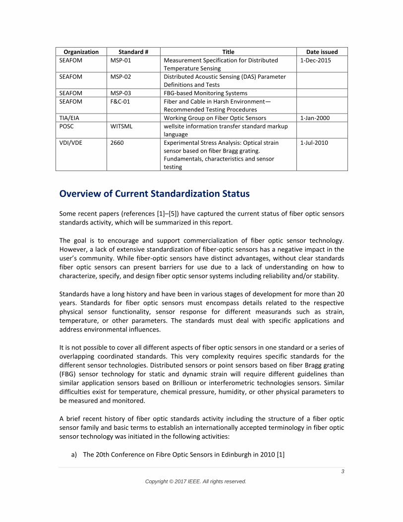
Organization Standard # Title Date issued
SEAFOM MSP-01 Measurement Specification for Distributed Temperature Sensing
1-Dec-2015
SEAFOM MSP-02 Distributed Acoustic Sensing (DAS) Parameter Definitions and Tests
SEAFOM MSP-03 FBG-based Monitoring Systems
SEAFOM F&C-01 Fiber and Cable in Harsh Environment—Recommended Testing Procedures
TIA/EIA Working Group on Fiber Optic Sensors 1-Jan-2000
POSC WITSML wellsite information transfer standard markup language
VDI/VDE 2660 Experimental Stress Analysis: Optical strain sensor based on fiber Bragg grating. Fundamentals, characteristics and sensor testing
1-Jul-2010
Overview of Current Standardization Status
Some recent papers (references [1]–[5]) have captured the current status of fiber optic sensors standards activity, which will be summarized in this report.
The goal is to encourage and support commercialization of fiber optic sensor technology. However, a lack of extensive standardization of fiber-optic sensors has a negative impact in the user’s community. While fiber-optic sensors have distinct advantages, without clear standards fiber optic sensors can present barriers for use due to a lack of understanding on how to characterize, specify, and design fiber optic sensor systems including reliability and/or stability.
Standards have a long history and have been in various stages of development for more than 20 years. Standards for fiber optic sensors must encompass details related to the respective physical sensor functionality, sensor response for different measurands such as strain, temperature, or other parameters. The standards must deal with specific applications and address environmental influences.
It is not possible to cover all different aspects of fiber optic sensors in one standard or a series of overlapping coordinated standards. This very complexity requires specific standards for the different sensor technologies. Distributed sensors or point sensors based on fiber Bragg grating (FBG) sensor technology for static and dynamic strain will require different guidelines than similar application sensors based on Brillioun or interferometric technologies sensors. Similar difficulties exist for temperature, chemical pressure, humidity, or other physical parameters to be measured and monitored.
A brief recent history of fiber optic standards activity including the structure of a fiber optic sensor family and basic terms to establish an internationally accepted terminology in fiber optic sensor technology was initiated in the following activities:
a) The 20th Conference on Fibre Optic Sensors in Edinburgh in 2010 [1]
4
Copyright © 2017 IEEE. All rights reserved.
b) The European COST Action 299 “FIDES” (Optical Fibres for New Challenges Facing the Information Society)
The COST action was the basis for further progress
c) “Guideline for Use of Fibre Optic Sensors” was developed and published in 2009. Contents include the following: 1) Basic terms 2) Basic sensor categories 3) General terms affecting all or most fiber-optic sensors 4) Types of used fibers 5) Functionality terms
Fatigue Life expectancy/lifetime Durability Failure criteria Resolution Accuracy Location accuracy Distance accuracy Repeatability Stability Optical safety
d) The generic fiber-optic IEC Standard (IEC 61757:1995) was then revised and completed in 2011 and 2012
e) Publication of the first IEC generic standard on “Fibre Optic Sensors” in 2012, the IEC 61757-1, provided a document that describes the basic function and necessary generic procedures to characterize and validate fiber optic sensing systems
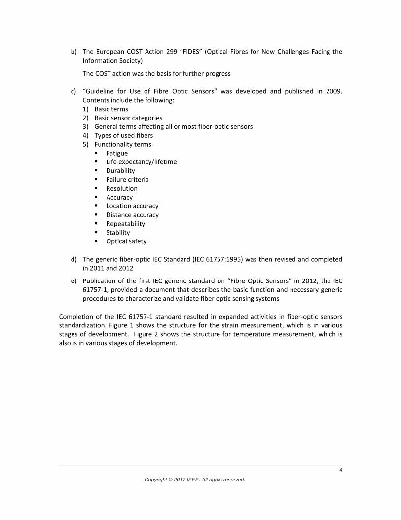
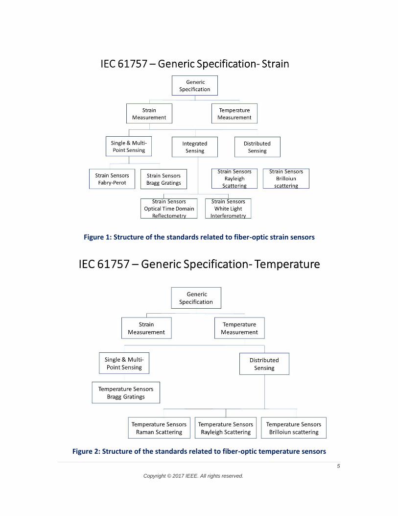
Completion of the IEC 61757-1 standard resulted in expanded activities in fiber-optic sensors standardization. Figure 1 shows the structure for the strain measurement, which is in various stages of development. Figure 2 shows the structure for temperature measurement, which is also is in various stages of development.
5
Copyright © 2017 IEEE. All rights reserved.
Figure 1: Structure of the standards related to fiber-optic strain sensors
Figure 2: Structure of the standards related to fiber-optic temperature sensors
6
Copyright © 2017 IEEE. All rights reserved.
In parallel activities, SEAFOM in March 2013 issued the Document SEAFOM-F&C-01, Fiber and Cable in Harsh Environments Recommended Testing Procedure (see Appendix I). This document outlines recommended test procedures for the primary parameters of optical fibers and cables used in oil and gas applications such as distributed temperature sensing. The goal of the document is to define a series of recommended practices to assess the performance of fiber and cable. The document does not recommend specification values that are the responsibility of various manufacturers.
The document identifies the existence of various standards and documented test methods for some of the fiber/cable parameters. Wherever applicable, existing methods are recommended to avoid duplication and confusion and to build on the existing industry-based testing platform. The focus for this document is on features and parameters that are specific to the oil and gas environments and applications that represent important information for the prediction of the lifetime of fiber/cable in operation. The documentation provides details on fiber testing, environmental testing, and cable testing including characterization procedures.
SEAFOM in January 2016 issued the Document SEAFOM-MSP-01, Measurement Specification for Distributed Temperature Sensing (see Appendix I).
The focus of this document is on “Distributed Temperature Sensing” (DTS). It is intended to be used as a guide to characterize the performance of any DTS as defined by the measurement parameters and a standardized set of measurement practices defined in the document including the following:
Test setups Procedures Calculation methods
It is not intended to define specific acceptance criteria for any given application. Also, it is not intended to limit the ability for any user to use any brand of DTS with any desired fiber and cable that is compatible with such system. The objective is to describe a harmonized set of DTS performance testing procedures. The testing procedures are valid for any brand or model of a DTS system. This document does not set any performance requirements on the actual DTS system being tested.
SEAFOM has working groups focusing on DTS systems, Fiber Bragg measurements, and downhole connectors.
Gap Analysis
As a general statement, the numerous organizations working on standards are addressing the broad range of sensor technologies, various measurement parameters such as strain and temperature, as well as sensing system characterization and qualification. It is recognized there is significant levels of proprietary technology and the goal of these organizations is not to discourage innovation. The major issue is tracking what standards exist and what areas are
7
Copyright © 2017 IEEE. All rights reserved.
active and would, therefore lend themselves well to further standards. There is no central location for a developer or potential end user to get a comprehensive overview of all the standards and standards issues. This is a serious gap that the IEEE can address. However, duplicating the effort of other sensor groups is not a good use of resources.
In the IEEE activities on fiber optic standards, the Specialty Fiber Cooperation Group identified the following areas for further fiber-related activity in its Gap analysis:
a) Cost
b) Lifetime
c) Termination
Connector attachment
Splicing—recoat
d) Adequacy of existing standards
e) Expanded temperature range →800 °C
Activity within the group is in progress.
Appendix II gives a summary of the standards work that was done by the Fiber Optic Sensor Consortium before it separated from OIDA (Optoelectronics Industry Development Association). The focus was on standardizing Bragg gratings. A key effort was to standardize Bragg grating wavelengths using the ITU grid format. As the industry expands, unspecified gratings will make inventory and distribution problematic. This activity was discontinued but not resolved and remains a potential gap.
Summary of Activities and Recommendations
Standardization activities to provide fiber optic sensors for their use in structural health monitoring systems (smart systems) as well as oil and gas applications have been aggressively pushed in the last 10 years. The generic IEC FOS standard and first basic sensor standards as well as application guidelines are available. A number of groups and committees are working on parallel activities. However, communication between participants of these groups is very important to avoid parallel activities that result in conflicts in terminology and recommendations. Continued close cooperation between participants from IEC, ISHMII, ASTM, SAE, IEEE, SEAFOM, and other standardization and guideline groups should be strongly encouraged and supported by industry and government groups.
The combination of efforts by ISIHMI, IEC, and SEAFOM (in terms of generation standards) are making progress in defining how to use, characterize, and provide reliable measurement data for the key dominate fiber optic sensor technologies. It is strongly recommended that IEEE not duplicate these efforts, but to disseminate standards information broadly and comprehensively as well as identify gaps that are not being covered and refer them to the proper standards organization.
8
Copyright © 2017 IEEE. All rights reserved.
References
[1] Wolfgang R. Habel, K. Krebber, W. Daum, “Results in standardization of FOS to support the use of SHM systems,” Sixth European Workshop on Optical Fibre Sensors, edited by Elfed Lewis, Proc. of SPIE Vol. 9916,2016. [2] Wolfgang R. Habel, K. Krebber, W. Daum, “Standardization in Fibre-optic Sensing for Structural Safety Activities in the ISHMII and IEC,” Smart Sensor Phenomena, Technology, Networks, and Systems Integration 2015, edited by Kara J. Peters, Proc. of SPIE Vol. 9436. [3] Habel, W.R. et al., “Guidelines for the characterization and use of fibre optic sensors: basic definitions and proposed standard for FBG-based strain sensors,” Proc. SPIE 7503, 75035E (2009). [4] COST 299, “Guideline for Use of Fibre Optic Sensors,” Document of the COST 299 Action FIDES (Optical Fibres for New Challenges Facing the Information Society). Published in September 2009. [5] IEC 61757-1 ED. 2.0 B:2011 “Fiber Optic Sensors—Part 1: Generic Specification,” IEC (2012).
9
Copyright © 2017 IEEE. All rights reserved.
Appendix I Summaries of Existing Fiber Optic Sensor Standards
ISA TR12.21.01 Use of Fiber Optic Systems in Class I Hazardous (Classified) Locations Organization: International Automation Society Document number: ISA TR 12.21.01 Publication date: 08-15-2004 Reference: http://standards.globalspec.com/std/1645624/isa-tr12-21-01
Summary This technical report provides guidance on the safe use of fiber optic systems and their constituent parts producing or guiding visible, near infrared, or mid infrared (maximum wavelength of 10 μm) radiation in Class I hazardous (classified) locations. Hazardous (classified) locations are described in the National Electrical Code® (NEC®).1 Limiting levels prescribed in this document apply only to the minimum levels of optical power, optical power density, and optical energy needed to ignite explosive gas atmospheres. In apparatus where optical energy is transduced to electrical energy, the limiting values for the electrical energy must be determined from relevant standards for electrical apparatus [e.g., ANSI/ISA-12.00.01-2002 (IEC 60079-0 Mod)].
At this time there is minimal awareness of the potential risk associated with optical ignitions even though fiber optics have been used for at least 20 years in hazardous (classified) locations. One purpose of this technical report is to inform industry of potential ignition hazards associated with the use of fiber optic systems in explosive gas atmospheres. The technical report is also intended to suggest engineering and installation practices to reduce the ignition hazard from fiber optic systems in Class I locations.
1National Electrical Code, NEC, and NFPA 70 are registered trademarks of the National Fire Protection Association.
10
Copyright © 2017 IEEE. All rights reserved.
ASTM F3079-14 Standard Practice for Use of Distributed Optical Fiber Sensing Systems for Monitoring the Impact of Ground Movements During Tunnel and Utility Construction on Existing Underground Utilities Organization: American Society Testing Materials Document number: ASTM F3079-14 Publication date: 10-01-2014 Reference: https://www.astm.org/Standards/F3079.htm
Summary This practice is intended to assist engineers, contractors, and owner/operators of underground utilities and tunnels with the successful implementation of distributed optical fiber sensing for monitoring ground movements prior to construction for site planning and during utility and tunnel construction and operation and the impact of such ground movements on existing utilities.
Before the installation of distributed optical fiber sensing begins, the contractor shall secure written explicit authorization from the owner/operator of the new tunnel/utility and the existing utilities allowing an evaluation to be conducted for the feasibility of distributed optical fiber sensing for monitoring ground movements for the intended purpose and to have access to certain locations of the structure and the surrounding ground. It may also be necessary for the installer to have written explicit authorization from applicable jurisdictional agencies such as the Department of Transportation, the Army Corps of Engineers, the Department of Environmental Protection, and others.
Engineers, contractors, and owners/operators shall also be cognizant of how the use of distributed optical fiber sensing for monitoring ground movements around utilities and tunnels might interfere with the use of certain equipment or tools near the installed optical fiber sensing cable in some special situations. For example, repair activities may have to temporarily remove, relocate, or avoid the optical fiber cable.
Engineers, contractors, and owners/operators should be cognizant of how installation techniques and optical fiber (OF) cable location and protection can affect the performance of DOFSS (Distributed Optical Fiber Sensing Systems).
This practice specifically addresses the means and methods for the use of distributed optical fiber sensors for monitoring ground movements during tunnel and utility construction and its impact on existing utilities.
11
Copyright © 2017 IEEE. All rights reserved.
This practice applies to the process of selecting suitable materials, design, installation, data collection, data processing, and reporting of results.
This practice applies to all utilities that transport water, sewage, oil, gas, chemicals, electric power, communications, and mass media content.
This practice applies to all tunnels that transport and/or store water or sewage.
This practice also applies to tunnels that carry the utilities in water for hydropower, traffic, rail, freight, capsule transport, and those used for storage.
This standard does not purport to address all of the safety concerns, if any, associated with its use. It is the responsibility of the user of this standard to establish appropriate safety and health practices and determine the applicability of regulatory limitations prior to use.
ASTM F3092-14 Standard Terminology Relating to Optical Fiber Sensing Systems
Organization: American Society Testing Materials Document number: ASTM F3079-14 Publication date: 01-01-2014 Reference: https://www.astm.org/Standards/F3092.htm
Summary Definitions in this standard are to be regarded as correct for the terms found in other ASTM standards of Committee F36. Certain terms may be found in more than one standard issued under the jurisdiction of this committee and many of these terms have been placed in this standard.
This terminology standard is a compilation of definitions of technical terms related to optical fiber sensing systems, used in the various sections of standards under the jurisdiction of ASTM Committee F36.
Where possible, definitions are stated as a single sentence, with necessary supplementary information as a discussion. This approach is used to simplify explanations of the meanings of technical terms for the benefit of those not conversant with them, to facilitate a precise understanding and interpretation of F36 ASTM standards.
12
Copyright © 2017 IEEE. All rights reserved.
ASTM F2070-00 (2011) Standard Specification for Transducers, Pressure and Differential, Pressure, Electrical and Fiber-Optic Organization: American Society Testing Materials Document number: ASTM F2070-00 (2011) Publication date: 12-01-2000, Revised 2011 Reference: https://www.astm.org/Standards/F2070.htm
Summary This specification covers the requirements for pressure and differential pressure transducers for general applications. Pressure transducers typically consist of a sensing element that is in contact with the process medium and a transduction element that modifies the signal from the sensing element to produce an electrical or optical output. Some parts of the transducer may be hermetically sealed if those parts are sensitive to and may be exposed to moisture. Pressure connections must be threaded with appropriate fittings to connect the transducer to standard pipe fittings or to other appropriate leak-proof fittings. The output cable must be securely fastened to the body of the transducer. Most common sensing elements are diaphragms, bellows, capsules, Bourdon tubes, and piezoelectric crystals. The function of the sensing element is to produce a measurable response to applied pressure or vacuum. The response may be sensed directly on the element or a separate sensor may be used to detect element response. The following are the different types of electrical pressure transducers: differential transformed transducer, potentiometric transducer, strain gage transducer, variable reluctance transducer, and piezoelectric transducer. Different kinds of fiber optic pressure transducers shall be discussed: Fabry-Perot interferometer, Bragg grating interferometer, quartz resonator, and micromachined membrane/diaphragm deflection. The following physical properties of transducers shall be determined: enclosure, transducer mounting, external configuration, standard electrical connection, pressure connections, damping, size, and weight. Different tests shall be conducted in order to determine the service life and overall performance of the transducers.
This specification covers the requirements for pressure and differential pressure transducers for general applications.
This standard does not purport to address all of the safety concerns, if any, associated with its use. It is the responsibility of the user of this standard to establish appropriate safety and health practices, and determine the applicability of regulatory limitations prior to use.
Special requirements for naval shipboard applications are included in Supplementary Requirements S1, S2, and S3.
13
Copyright © 2017 IEEE. All rights reserved.
ASTM E1614–94 (2013) Standard Guide for Procedure for Measuring Ionizing Radiation-Induced Attenuation in Silica-Based Optical Fibers and Cables for Use in Remote Fiber-Optic Spectroscopy and Broadband Systems
Organization: American Society Testing Materials Document number: ASTM E1614-94 (2013) Publication date: December 1, 1994, Revised 2013 Reference: https://www.astm.org/search/fullsite-search.html?query=E13.09&
Summary Ionizing environments will affect the performance of optical fibers/cables being used to transmit spectroscopic information from a remote location. Determination of the type and magnitude of the spectral attenuation or interferences, or both, produced by the ionizing radiation in the fiber is necessary for evaluating the performance of an optical fiber sensor system.
The results of the test can be utilized as a selection criterion for optical fibers used in optical fiber spectroscopic sensor systems.
Note 1—The attenuation of optical fibers generally increases when exposed to ionizing radiation. This is due primarily to the trapping of radiolytic electrons and holes at defect sites in the optical materials, that is, the formation of color centers. The depopulation of these color centers by thermal and/or optical (photobleaching) processes, or both, causes recovery, usually resulting in a decrease in radiation-induced attenuation. Recovery of the attenuation after irradiation depends on many variables, including the temperature of the test sample, the composition of the sample, the spectrum and type of radiation employed, the total dose applied to the test sample, the light level used to measure the attenuation, and the operating spectrum. Under some continuous conditions, recovery is never complete.
This guide covers a method for measuring the real time, in situ radiation-induced spectral attenuation of multimode, step index, silica optical fibers transmitting unpolarized light. This procedure specifically addresses steady-state ionizing radiation (that is, alpha, beta, gamma, protons, etc.) with appropriate changes in dosimetry, and shielding considerations, depending upon the irradiation source.
This test procedure is not intended to test the balance of the optical and non-optical components of an optical fiber-based system, but may be modified to test other components in a continuous irradiation environment.
This standard does not purport to address all of the safety concerns, if any, associated with its use. It is the responsibility of the user of this standard to establish appropriate safety and health practices and determine the applicability of regulatory limitations prior to use.
14
Copyright © 2017 IEEE. All rights reserved.
ASTM E1653–94 (2013) Standard Guide for Specifying Dynamic Characteristics of Optical Radiation Transmitting Fiber Waveguides
Organization: American Society Testing Materials Document number: ASTM E1653-94 (2013) Publication date: Revised 2013 Reference: https://www.astm.org/search/fullsite-search.html?query=E13.09&
Summary Many characteristics of a fiber-optic waveguide affect the dynamic performance. Quantitative values of certain key parameters (characteristics) need to be known, a priori, in order to predict or evaluate the dynamic performance of a waveguide for specific conditions of use. This guide identifies these key parameters and provides information on their significance and how they affect performance. However, this guide does not describe how the needed quantitative information is to be obtained. Manufacturers of fiber optic waveguides can use this guide for characterizing their products suitably for users who are concerned with dynamic performance. Users of fiber optic waveguides can use this guide to determine that their waveguides are adequately characterized for their intended application.
This guide covers the key parameters that determine the dynamic performance of an optical radiation transmitting fiber waveguide (see Note 1). For the purpose of this guide, optical radiation is electromagnetic radiation of wavelengths from about 200 nm to about 5000 nm (correspondingly, frequencies of 50 000 cm−1 to 2000 cm−1, and photon energies of 6 eV to 0.25 eV).
NOTE 1—Typical designations of radiation transmitting fiber waveguides include optical waveguide, fiber-optic, fiber-optic waveguide, and fiber-optic radiation guide.
This standard does not purport to address all of the safety concerns, if any, associated with its use. It is the responsibility of the user of this standard to establish appropriate safety and health practices and determine the applicability of regulatory limitations prior to use.
IEC 61757-1:2012 Fibre optic sensors—Part 1: Generic specification Organization: International Electrotechnical Commission Document number: IEC 61757-1:2012 Publication date: May 12, 2012 Reference: https://webstore.iec.ch/publication/5867
15
Copyright © 2017 IEEE. All rights reserved.
Summary IEC 61757-1:2012 is a generic specification covering optical fibres, components and sub-assemblies as they pertain specifically to fibre optic sensing applications. It has been designed to be used as a common working and discussion tool by the vendor of components and subassemblies intended to be integrated in fibre optic sensors, as well as by designers, manufacturers and users of fibre optic sensors independent of any application or installation. The objective of this generic specification is to define, classify and provide the framework for specifying fibre optic sensors, and their specific components and subassemblies. The requirements of this standard apply to all related sectional, family, and detail specifications. Sectional specifications will contain requirements specific to sensors for particular quantities subject to measurement. Within each sectional specification, family and detail specifications contain requirements for a particular style or variant of a fibre optic sensor of that sectional specification. This edition includes a substantial technical update of all clauses, definitions, and cited references with respect to the previous edition.
IEC 61757-1-1:2016 Fibre optic sensors—Part 1-1: Strain measurement—Strain sensors based on fibre Bragg gratings Document number: IEC 61757-1-1:2016 Publication date: Feb 25, 2016 Reference: https://webstore.iec.ch/publication/24254
Summary IEC 61757-1-1:2016(E) defines detail specifications for fibre optic sensors using one or more fibre Bragg gratings (FBG) as the sensitive element for strain measurements. Generic specifications for fibre optic sensors are defined in IEC 61757-1:2012. This standard specifies the most important features and characteristics of a fibre optic sensor for strain measurements based on use of an FBG as the sensitive element, and defines the procedures for their determination. Furthermore, it specifies basic performance parameters and characteristics of the corresponding measuring instrument to read out the optical signal from the FBG. This standard refers to the measurement of static and dynamic strain values in a range of frequencies. A blank detail specification is provided in Annex B. Keywords: Bragg gratings (FBG), strain measurement of fibre optic sensors
16
Copyright © 2017 IEEE. All rights reserved.
IEC 61757-3-1: (IEC 86C/1267/CD:2014) (German) Fibre optic sensors—Part 3-1: Temperature measurement—Distributed sensing Document number: IEC 61757-3-1:2014 Publication date: Feb 6, 2014 Reference: http://www.din.de/en/getting-involved/standards-committees/dke/projects/wdc-proj:din21:201456484
Summary This part of IEC 61757 defines detail specifications for distributed temperature measurement by a fibre optic sensor, also known as fibre optic distributed temperature sensing (DTS). DTS includes the use of Raman scattering, Brillouin scattering and Rayleigh scattering effects. In addition, Raman scattering and Rayleigh scattering based measurements are performed with a single-ended fibre configuration only. Brillouin scattering based measurements are performed with a single-ended fibre or fibre loop configuration. The technique accessible from both sides at same time (e.g. Brillouin optical time domain analysis, BOTDA) is referred to here as a loop configuration. Generic specifications for fibre optic sensors are defined in IEC 61757-1.
IEC 60044-7:1999 Instrument transformers - Part 7: Electronic voltage transformers Document number: IEC 60044-7:1999 Publication date: Dec 17, 1999 Reference: https://webstore.iec.ch/publication/156
Summary Applies to newly-manufactured electronic voltage transformers with analogue output, for use with electrical measuring instruments and electrical protective devices at frequencies from 15 Hz to 100 Hz. The standard covers optical arrangements with electronic components. Three-phase voltage transformers are not included, but some of the requirements apply.
17
Copyright © 2017 IEEE. All rights reserved.
IEC 60044-8:2002 Instrument transformers—Part 8: Electronic current transformers Document number: IEC 60044-8:2002 Publication date: Jul 19, 2002 Reference: https://webstore.iec.ch/publication/157
Summary This part of IEC 60044 applies to newly-manufactured electronic current transformers having an analogue voltage output or a digital output, for use with electrical measuring instruments and electrical protective devices at nominal frequencies from 15 Hz to 100 Hz.
IEC 61869-6:2016 Instrument transformers - Part 6: Additional general requirements for low-power instrument transformers
Document number: IEC 61869-6:2016 Publication date: Apr 22, 2016 Reference: https://webstore.iec.ch/publication/24662
Summary IEC 61869-6:2016(E) is a product family standard and covers only additional general requirements for low-power instrument transformers (LPIT) used for ac. applications having rated frequencies from 15 Hz to 100 Hz covering MV, HV, and EHV or used for dc applications. This product standard is based on IEC 61869-1:2007, in addition to the relevant product specific standard. This part of IEC 61869 does not cover the specification for the digital output format of instrument transformers. This part of IEC 61869 defines the errors in case of analogue or digital output. The other characteristics of the digital interface for instrument transformers are standardized in IEC 61869-9 as an application of the standards, the IEC 61850 series, which details layered substation communication architecture. This part of IEC 61869 considers additional requirements concerning bandwidth. General Requirements; however, the reader is encouraged to use its most recent edition. This first edition of IEC 61869-6 cancels and replaces the relevant parts of IEC 60044-7, published in 1999, and of IEC 60044-8, published in 2002.
18
Copyright © 2017 IEEE. All rights reserved.
IEEE Std 952™-1997
IEEE Standard Specification Format Guide and Test Procedure for Single-Axis Interferometric Fiber Optic Gyros Document number: IEEE Std 952-1997 Publication date: Jan 1, 1997 Reference: https://standards.ieee.org/findstds/standard/952-1997.html
Summary Specification and test requirements for a single-axis interferometric fiber optic gyro (I FOG) for use as a sensor in attitude control systems, angular displacement measuring systems, and angular rate measuring systems are defined. A standard specification format guide for the preparation of a single-axis IFOG is provided. A compilation of recommended procedures for testing a fiber optic gyro, derived from those presently used in the industry, is also provided.
IEEE Std 1601™-2010 IEEE Trial-Use Standard for Optical AC Current and Voltage Sensing Systems Document number: IEEE Std 1601-2010 Publication date: Dec 13, 2010 Reference: https://standards.ieee.org/findstds/standard/952-1997.html
Summary The performance of optical current and voltage measurement systems used in the generation, transmission, and distribution of alternating current electricity, and to assist in the proper selection of such equipment is described in this trial-use standard. This standard covers certain physical characteristics of the sensing systems that use optical techniques to measure current and voltage. This standard provides the requirements for the performance characteristics and the test of optical current and voltage sensors of a nominal system voltage of 1 kV and above, the information related to the nature of these sensors, and the information related to the application and use of these sensors.
19
Copyright © 2017 IEEE. All rights reserved.
NPFC-NAVY-MIL-S-24795 Sensors, Temperature, Fiber Optic (Naval Shipboard Use) Document number: MIL-S-24795 Publication date: Jun 22, 1995 Reference: http://standards.globalspec.com/std/354560/npfc-mil-s-24795
Summary This specification covers single-channel, fiber optic temperature sensors (FOTS) for Naval shipboard use, but does not include the readout display.
SAE AIR 6258 Fiber Optic Sensors for Aerospace Applications Document number: SAE AIR 6258 Publication date: Jun 12, 2015 Reference: http://standards.sae.org/wip/air6258/
Summary This document is intended to describe technologies available, application needs, and operational requirements relating to the use of fiber optic sensing systems on aerospace platforms:
a) To define standard terminology used in describing fiber optic sensing systems and their performance. b) To identify current interfaces used for fiber optic sensing systems. c) To define environmental, reliability, and maintainability capabilities of fiber optic sensing system components. d) To describe the fiber optic sensor and instrumentation technologies that forms the current state of the art. e) To describe current and future unmet needs of the aerospace industry for measurements using fiber optic sensors.
The purpose of this document is to aid in sensor system selection for aerospace applications. It describes both generic and specific qualities of key fiber optic sensing technologies and the range of measurement tasks they are able to perform. This includes a critical and comprehensive comparison between specific optical sensor technologies, currently available, and corresponding non-optical sensing methods. This will assist aircraft component and
20
Copyright © 2017 IEEE. All rights reserved.
subsystem designers to assess their suitability and potential for specific applications and assist in an appraisal of technology maturity levels and technology gaps.
Guidelines on the use and application of classes of fiber optic sensors are given including the following:
Sensor and system compatibility (including fiber cable, connectors, interrogator, signal conditioning, network interface, and power requirements)
Compatibility with aircraft systems, Standard forms of interrogation/interface Proposed methods of standardization Qualification recommendations
SAE ARP6366 Fiber Optic Sensor Specification Guidelines for Aerospace Applications Document number: SAE ARP 6366 Publication date: Feb 17, 2017 Reference: http://standards.globalspec.com/std/354560/npfc-mil-s-24795
Summary This ARP document defines a comprehensive and widely-accepted set of guidelines for use or design of fiber optic sensors on aerospace applications.
This Aerospace Recommended Practice (ARP) presents a comprehensive and widely-accepted vocabulary, parameters, and practices for fiber optic sensors for aerospace applications. Fiber optic sensors on aerospace platforms will profit from improved coordination between developers, specifiers, program managers, and end users.
SEAFOM-MSP-01 Measurement Specification for Distributed Temperature Sensing
Document number: SEAFOM-MSP-01 Publication date: Dec 1, 2015 Reference: http://www.seafom.com/index.php/documents/knowledge-sharing?task=document.viewdoc&id=7
21
Copyright © 2017 IEEE. All rights reserved.
Summary This document was written by and on the initiative of the SEAFOM Measurement Specifications Working Group. It is targeted specifically for “Distributed Temperature Sensing” (DTS). It is intended to be used as a guide to enable the characterization of performance of any DTS as defined by the measurement parameters and via the use of a standardized set of measurement practices contained: including test setups, procedures, and calculation methods. It is not intended to actually define any specific acceptance criteria for any given application, neither to limit the ability for any user to use any brand of DTS with any desired fiber and cable that is compatible with such system. The temperature controlling devices and the reference measurement equipment that are required to support these setups and procedures do not require any particular class of performance. However, their performance parameters will limit the quality of the determination of the various fiber measurement parameters
The objective of this document is to describe a harmonized set of DTS performance testing procedures. The testing procedures are valid for any brand or model of a DTS system. This document does not pose any requirements on the actual DTS system performance
The scope of this document is to specify the measurement procedure for obtaining the following DTS performance parameters:
Calibration Error Spatial Resolution Temperature Repeatability Spatial Temperature Resolution Environmental Temperature Stability Warm up time
SEAFOM-F&C-01 Fiber and Cable in Harsh Environment—Recommended Testing Procedures Document number: SEAFOM-F&C-01 Publication date: March, 2013 Reference: http://www.seafom.com/index.php/documents/knowledge-sharing?task=document.viewdoc&id=8
Summary This document describes recommended test procedures for the key parameters of optical fibers and cables used in Oil and Gas applications such as Distributed Temperature Sensing, Logging, and other downhole measurements. The intent of the document is merely a series of
22
Copyright © 2017 IEEE. All rights reserved.
recommended practices to assess the performance of fiber and cable, and not specification values for the various parameters to be met by the manufacturer.
The Fiber and Cable working group recognizes the existence of various standards and documented test methods for some of the fiber/cable parameters. Therefore, wherever applicable, existing methods are recommended throughout this document. Most of the focus for this document is on features and parameters that are specific to the oil and gas environments and applications that represent important information for the prediction of the lifetime of fiber/cable in operation.
POSC-WITSML Wellsite Information Transfer Standard Markup Language Document number: POSC-WITSML Publication date: 2003 Reference: http://w3.energistics.org/schema/witsml_v1.3.1_data/doc/DTS_Overview.html
Summary This document contains descriptions of data types produced by optic fiber based Distributed Temperature Survey data from oil wells. This document describes a proposed transfer standard for Distributed Temperature Survey (DTS) data profiles measured using optic fiber techniques along wellbores drilled for the production of oil and gas. The DTS data are specified re-using many relevant WITSML definitions.
VDI/VDE 2660 (The Association of German Engineers–VDI) Experimental Stress Analysis: Optical Strain Sensor Based on Fiber Bragg Grating: Fundamentals, Characteristics and Sensor Testing
Document number: VDI/VDE 2660 Publication date: July, 2010 Reference: http://www.vdi.eu/nc/guidelines/vdivde_2660_blatt_1-experimentelle_strukturanalyse_optischer_dehnungssensor_basierend_auf_faser_bragg_gitter_/
23
Copyright © 2017 IEEE. All rights reserved.
Summary
The guideline defines the characteristics for the assessment of optical strain sensors (OSS) and describes testing procedures for them. With the guideline the manufacturer of optical strain sensors is given directions for their production and description, and the user a better understanding regarding the selection, application and operation of optical strain sensors. In addition the definitions in the guideline improve the feedback between the manufacturer and the user of optical strain sensors, since defined characteristics constitute a mutual, commonly understood basis for their communication. The guideline is aimed at manufacturers and users of optical strain sensors. Besides the production units, the provinces marketing and distribution are also addressed.
24
Copyright © 2017 IEEE. All rights reserved.
Appendix II Standards activity—Other organizations
SIIS—Subsea Instrumentation Interface Standardisation
The organization was established in 2003. The goal is to create an open standard for the benefit of the oil and gas industry. SIIS recently finished producing the Recommended Practice (RP) and text for an API Standard, which defines three instrument interface protocols for communication between subsea control modules and subsea sensors.
SIIS has 27 member companies consisting of controls systems suppliers, instrument suppliers and operators.
OIDA Fiber Optic Sensor Consortium (2010)
The Fiber Optic Sensor Consortium separated from OIDA in late 2010 and focused on market projections and discontinued standards activity.
Standards Overview — Without standards, fiber optic sensor networks will remain custom niche (relatively
small) market opportunity
Focus Activities — The primary Consortium focus is on applications/markets. It is recognized that
specific Consortium activities will recognize technology approaches as they relate to market segmentation and preliminary standards activity
— A major effort was to define specifications for Bragg gratings
Bragg grating specifications — Number of sensors to be included (suggest 20−50)
• The consensus was that the number of sensors can vary from a few to over 150. However, most applications at this point will require less than 40.
— Wavelength nm (Based on ITU grid) • Some respondents suggested that the use of the ITU grid was unnecessary.
However, as the industry expands unspecified gratings will make inventory and distribution problematic. Most suggested using the ITU grid, which makes grating manufacture compatible with telecommunications applications. A relaxed spec on the specific ITU grid wavelength from ±0.1 nm to ±0.25 nm should have a positive impact on cost without degrading functionality. The consensus was to use a course grating and a fine grating specification. The
25
Copyright © 2017 IEEE. All rights reserved.
center wavelength would be 1550.12 nm in the C band. For coarse gratings, the adjacent channels would be at 1554.94 nm and 1544.92 nm. The spacing is approximately 5 nm. Subsequent channels would be the ITU grid channel closest to a 5 nm change. This specification permits 10 channels in the C band (20 channels C & L band). For fine spacing, the adjacent channels to the center wavelength would be 1552.52 nm and 1547.32 nm. The spacing is approximately 2.5 nm that permits 20 channels in the C band (40 channels C & L band). Higher channel count would require a finer spacing specification.
• For those systems based on TDM multiplexing, adjacent channels have no meaning so tolerances can be relaxed.
— Grating length mm • 1 mm to 10 mm
— Reflectivity (suggest high version, low version) • The response from the committee was very wide • WDM - high reflectivity 30% to 90%; low reflectivity 0.5% to 10% • TDM - 0.05% to 10%
— Adjacent sensor wavelength spacing nm • WDM - 2.5 nm to 5 nm • TDM gratings use single wavelength
— Bandwidth nm • 2.5 nm
— Polarization dependent wavelength shift pm • WDM < 2 pm • TDM < 10 pm