Fiber-Optic Systems · 2018-04-25 · Fiber-Optic Systems 8 Fiber-Optic Systems Wavelength...
26
Fiber-Optic Systems 4 Fiber-Optic Systems Trunk Lines at the Moment ■ Migrating to Fiber Optics Trunk lines carry many different kinds of signals—video, synchronization, audio, control, power supply—and consequently they’re usually comprised of numerous different types of cables. As a result, conduits, electrical pits, and ladders tend to overflow with cabling, leaving hardly any room when lines must be added to upgrade or expand the system. But, converting these disparate signals into optical signals and transmitting them using fiber optic cables greatly reduces the need for so many specialized cables. Converting trunk lines to fiber optics makes it much easier to design and upgrade equipment and systems, because once laid these lines can be used with considerable flexibility. Fiber optic cables also have smaller diameters, meaning they take up less space, a clear advantage in alleviating some of the problems of today’s cable-stuffed broadcasting facilities. ■ Sending HD Signals Everywhere HD-SDI signals can be transmitted only about 100 meters over standard coaxial cables (5C-FB). This means that when wiring rooms and buildings with coaxial cables, it’s sometimes difficult to achieve an optimal layout or position equipment where it will be most convenient and useful. Further, signal transmissions often need to cover unexpectedly long distances, and fiber optic cables, with their transmission distance measured in tens of kilometers, win hands-down over coaxial cables. This flexibility alleviates much of the conventional worry about cable routing and allows the equipment itself to take center stage. The cost of optical signal converters has dropped radically, too—most can be had for a few hundred dollars—making it difficult these days to find reasons not to introduce fiber optic systems! This thin strand contains 4 optical fiber cores Fiber optic cable (100 cores) ∅11.5mm Coaxial cable 5C-FB ∅7.7mm Cable Diameters Even with 100 cores (lines), a fiber optic cable has an external diameter of just 11.5 mm. Compare that to a typical coaxial cable and the difference is clear. Example of an Optical Fiber Trunk Line Fiber optic systems are used in signal transmissions within a single broadcast station, or between a main building and an annex building. Optical Fiber Coaxial Annex Building Main Building Optical Converter Diversified Needs for Optical Conversion ■ It is not just the HD-SDI signal It is not just the HD-SDI signal that is converted into optical signals. For example, there is a case in which the HD-SDI signal is converted into optical signals along with the control signal to transmit video images during recording in a studio. Converting various signals into optical signals allows them to be transmitted through fiber-optic cables, eliminating the necessity of separately preparing metal cables. ■ Advantages of Fiber Optic Transmission in the Field With it now so easy to convert transmissions into optical signals, fiber optic systems are better suited than ever to field recording applications. Newly developed extra-strong, extra-bendable optical fibers have finally reduced past concerns about cable durability, meaning that in applications like remote broadcasting, video, audio and other signals can all be transmitted on a single cable, one of the inherent merits of fiber optic systems. 3G/HD-SDI Digital/Analog RS-422/RS-232 Ethernet Video Audio Control Network Tough & Flexible HFO Camera Cable (See page 20) Overview
Transcript of Fiber-Optic Systems · 2018-04-25 · Fiber-Optic Systems 8 Fiber-Optic Systems Wavelength...
Fiber-Optic Systems
4Fiber-Optic Systems
Trunk Lines at the Moment
■ Migrating to Fiber OpticsTrunk lines carry many different kinds of signals—video, synchronization, audio, control, power supply—and consequently they’re usually comprised of numerous different types of cables. As a result, conduits, electrical pits, and ladders tend to overflow with cabling, leaving hardly any room when lines must be added to upgrade or expand the system.But, converting these disparate signals into optical signals and transmitting them using fiber optic cables greatly reduces the need for so many specialized cables. Converting trunk lines to fiber optics makes it much easier to design and upgrade equipment and systems, because once laid these lines can be used with considerable flexibility. Fiber optic cables also have smaller diameters, meaning they take up less space, a clear advantage in alleviating some of the problems of today’s cable-stuffed broadcasting facilities.
■ Sending HD Signals EverywhereHD-SDI signals can be transmitted only about 100 meters over standard coaxial cables (5C-FB). This means that when wiring rooms and buildings with coaxial cables, it’s sometimes difficult to achieve an optimal layout or position equipment where it will be most convenient and useful. Further, signal transmissions often need to cover unexpectedly long distances, and fiber optic cables, with their transmission distance measured in tens of kilometers, win hands-down over coaxial cables. This flexibility alleviates much of the conventional worry about cable routing and allows the equipment itself to take center stage.The cost of optical signal converters has dropped radically, too—most can be had for a few hundred dollars—making it difficult these days to find reasons not to introduce fiber optic systems!
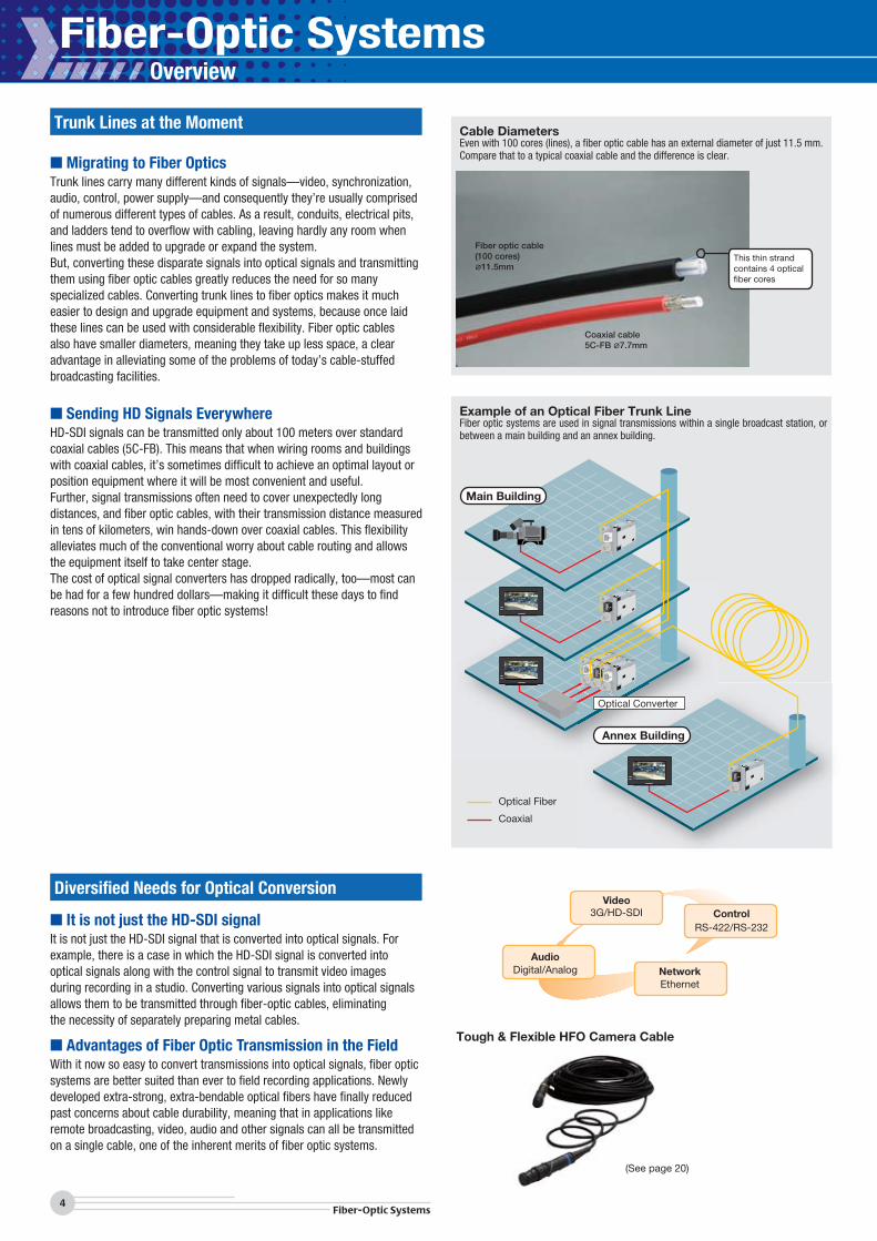
This thin strand contains 4 optical fiber cores
Fiber optic cable (100 cores) ∅11.5mm
Coaxial cable5C-FB ∅7.7mm
Cable DiametersEven with 100 cores (lines), a fiber optic cable has an external diameter of just 11.5 mm. Compare that to a typical coaxial cable and the difference is clear.
Example of an Optical Fiber Trunk LineFiber optic systems are used in signal transmissions within a single broadcast station, or between a main building and an annex building.
Optical Fiber
Coaxial
Annex Building
Main Building
Optical Converter
Diversified Needs for Optical Conversion
■ It is not just the HD-SDI signalIt is not just the HD-SDI signal that is converted into optical signals. Forexample, there is a case in which the HD-SDI signal is converted intooptical signals along with the control signal to transmit video imagesduring recording in a studio. Converting various signals into optical signalsallows them to be transmitted through fiber-optic cables, eliminatingthe necessity of separately preparing metal cables.
■ Advantages of Fiber Optic Transmission in the FieldWith it now so easy to convert transmissions into optical signals, fiber optic systems are better suited than ever to field recording applications. Newly developed extra-strong, extra-bendable optical fibers have finally reduced past concerns about cable durability, meaning that in applications like remote broadcasting, video, audio and other signals can all be transmitted on a single cable, one of the inherent merits of fiber optic systems.
3G/HD-SDI
Digital/Analog
RS-422/RS-232
Ethernet
Video
Audio
Control
Network
Tough & Flexible HFO Camera Cable
(See page 20)
Overview
5Fiber-Optic Systems
Technical TrendFiber-O
ptic Systems
ConnectorsCables
Panels & Patchbays
Mutichannel System
sCable A
ssemblies
Important Fiber Optic Line Considerations
■ Minimum Light Receiving Power
■ Loss Budget (LB)
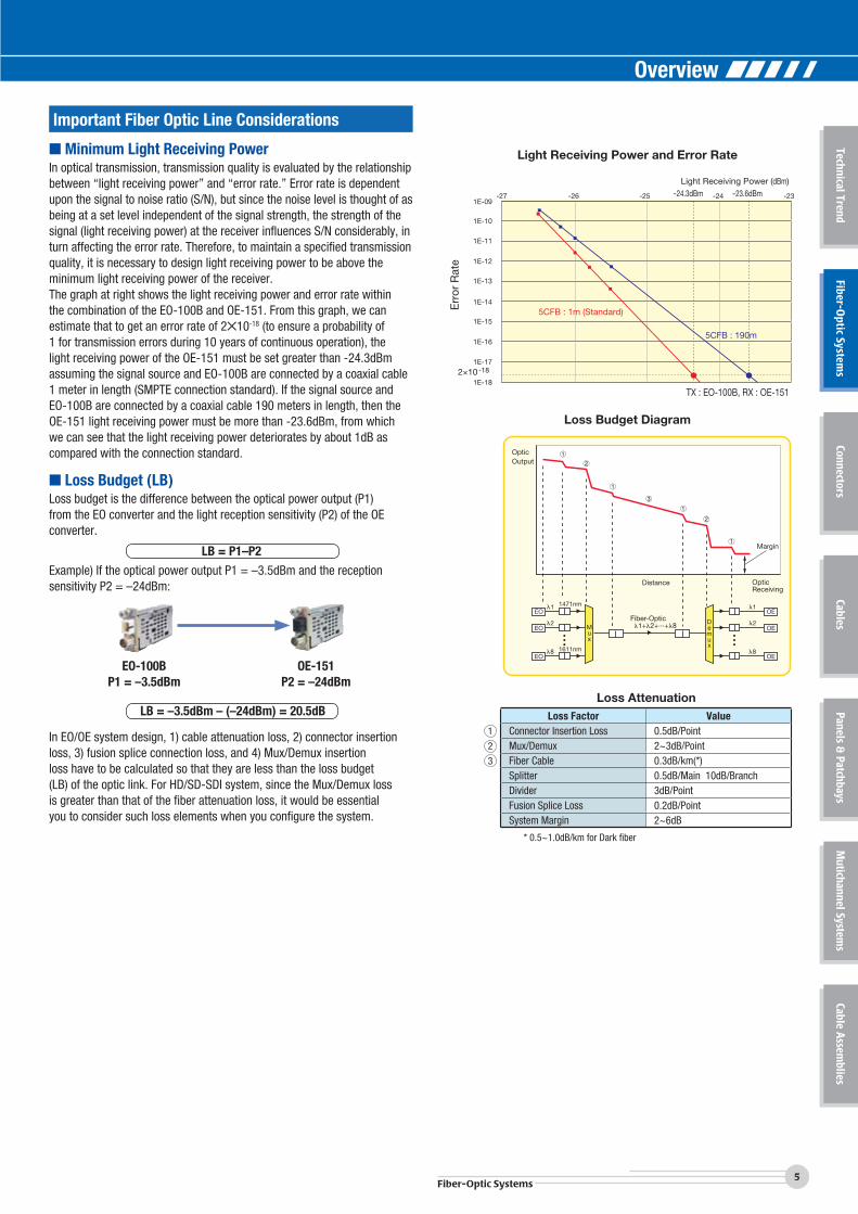
In optical transmission, transmission quality is evaluated by the relationship between “light receiving power” and “error rate.” Error rate is dependent upon the signal to noise ratio (S/N), but since the noise level is thought of as being at a set level independent of the signal strength, the strength of the signal (light receiving power) at the receiver influences S/N considerably, in turn affecting the error rate. Therefore, to maintain a specified transmission quality, it is necessary to design light receiving power to be above the minimum light receiving power of the receiver. The graph at right shows the light receiving power and error rate within the combination of the EO-100B and OE-151. From this graph, we can estimate that to get an error rate of 2✕10-18 (to ensure a probability of 1 for transmission errors during 10 years of continuous operation), the light receiving power of the OE-151 must be set greater than -24.3dBm assuming the signal source and EO-100B are connected by a coaxial cable 1 meter in length (SMPTE connection standard). If the signal source and EO-100B are connected by a coaxial cable 190 meters in length, then the OE-151 light receiving power must be more than -23.6dBm, from which we can see that the light receiving power deteriorates by about 1dB as compared with the connection standard.
Loss budget is the difference between the optical power output (P1)from the EO converter and the light reception sensitivity (P2) of the OEconverter.
LB = P1–P2
Example) If the optical power output P1 = –3.5dBm and the receptionsensitivity P2 = –24dBm:
1E-09-27 -26 -25 -24 -23
1E-10
1E-11
1E-12
1E-13
1E-14
1E-15
1E-16
1E-17
1E-182×10-18
-24.3dBmLight Receiving Power (dBm)
-23.6dBm
5CFB : 1m (Standard)
5CFB : 190m
TX : EO-100B, RX : OE-151
g g
Err
or R
ate
Light Receiving Power and Error Rate
�1
�2
�8
�1
�2
�8
Fiber-OpticMux
Demux
�1+�2+...+�8
1471nm
1611nm
EO
EO
EO
OE
OE
OE
OpticOutput
Distance Optic Receiving
Margin
Loss Budget Diagram
In EO/OE system design, 1) cable attenuation loss, 2) connector insertionloss, 3) fusion splice connection loss, and 4) Mux/Demux insertionloss have to be calculated so that they are less than the loss budget(LB) of the optic link. For HD/SD-SDI system, since the Mux/Demux lossis greater than that of the fiber attenuation loss, it would be essentialyou to consider such loss elements when you configure the system.
Loss AttenuationLoss Factor Value
1 Connector Insertion Loss 0.5dB/Point 2 Mux/Demux 2~3dB/Point 3 Fiber Cable 0.3dB/km(*)
Splitter 0.5dB/Main 10dB/BranchDivider 3dB/Point Fusion Splice Loss 0.2dB/Point System Margin 2~6dB
* 0.5~1.0dB/km for Dark fiber
LB = –3.5dBm – (–24dBm) = 20.5dB
EO-100BP1 = –3.5dBm
OE-151P2 = –24dBm
Overview
Fiber-Optic Systems
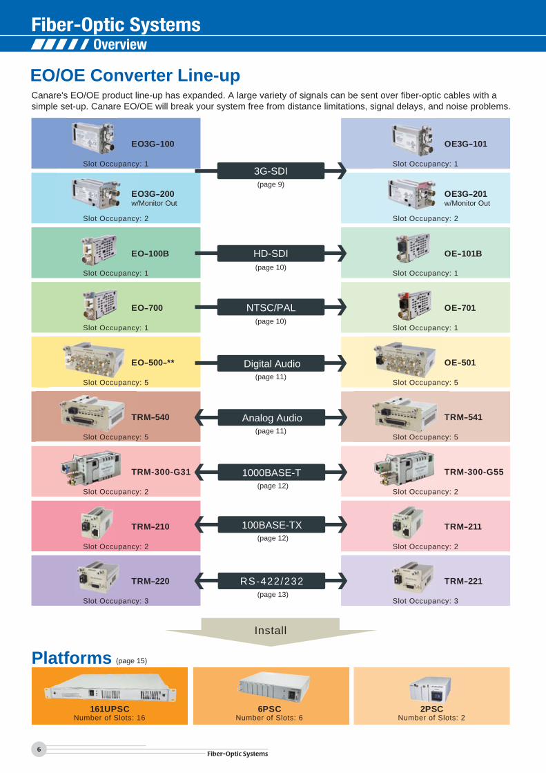
EO/OE Converter Line-up
Platforms (page 15)
Install
161UPSC 6PSC 2PSCNumber of Slots: 16 Number of Slots: 6 Number of Slots: 2
Canare's EO/OE product line-up has expanded. A large variety of signals can be sent over fiber-optic cables with a simple set-up. Canare EO/OE will break your system free from distance limitations, signal delays, and noise problems.
Slot Occupancy: 2 Slot Occupancy: 2
EO3G-200w/Monitor Out
OE3G-201w/Monitor Out
Slot Occupancy: 1 Slot Occupancy: 1
EO3G-100 OE3G-101
OE-101B
EO-700 OE-701
Slot Occupancy: 1 Slot Occupancy: 1p
EO-500-** OE-501
Slot Occupancy: 5 Slot Occupancy: 5
EO-100B
Slot Occupancy: 1Slot Occupancy: 1
TRM-210 TRM-211
Slot Occupancy: 2 Slot Occupancy: 2
TRM-220 TRM-221
Slot Occupancy: 3 Slot Occupancy: 3
HD-SDI
3G-SDI
NTSC/PAL
Digital Audio
100BASE-TX
RS-422/232
Analog Audio
1000BASE-T(page 12)
(page 13)
(page 12)
(page 11)
(page 11)
(page 10)
(page 10)
(page 9)
TRM-540 TRM-541
TRM-300-G31 TRM-300-G55
Slot Occupancy: 5 Slot Occupancy: 5
Slot Occupancy: 2 Slot Occupancy: 2
6Fiber-Optic Systems
Overview
Broadcast Booth
123456789
1011
EO3G-200
EO3G-200
OE3G-201
TRM-541
161UPSC1213141516
TRM-211
Operation Room
12345678910111213141516
EO3G-200
EO3G-200
TRM-210
TRM-220
12345678910111213141516
OE3G-101OE3G-101EO3G-100TRM-210
EO3G-100OE3G-101EO3G-100TRM-220
161UPSC
161UPSC
12345678910111213141516
OE3G-201
OE3G-201
EO3G-200
TRM-540
TRM-210
161UPSCRemote Camera
LED Screen
Main Camera
EO3G-100EO3G-100OE3G-101TRM-211
OE3G-101TRM-221
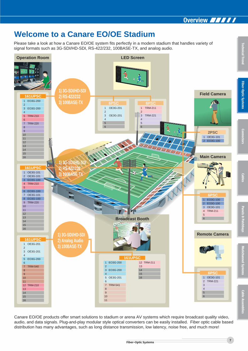
Welcome to a Canare EO/OE StadiumPlease take a look at how a Canare EO/OE system fits perfectly in a modern stadium that handles variety ofsignal formats such as 3G-SDI/HD-SDI, RS-422/232, 100BASE-TX, and analog audio.
Canare EO/OE products offer smart solutions to stadium or arena AV systems which require broadcast quality video, audio, and data signals. Plug-and-play modular style optical converters can be easily installed. Fiber optic cable based distribution has many advantages, such as long distance transmission, low latency, noise free, and much more!
6PSC 6PSC123456
OE3G-201
OE3G-201
123456
TRM-211
TRM-221
1) 3G-SDI/HD-SDI2) RS-422/2323) 100BASE-TX
1) 3G-SDI/HD-SDI2) RS-422/2323) 100BASE-TX
1) 3G-SDI/HD-SDI2) Analog Audio3) 100BASE-TX
6PSC
6PSC
Field Camera
OE3G-101EO3G-100
2PSC12
123456
123456
7Fiber-Optic Systems
Technical TrendFiber-O
ptic Systems
ConnectorsCables
Panels & Patchbays
Mutichannel System
sCable A
ssemblies
Overview
Fiber-Optic Systems
8Fiber-Optic Systems
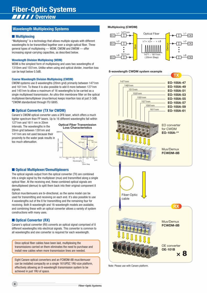
Wavelength Multiplexing Systems
Canare’s CWDM optical converter uses a DFB laser, which offers a much tighter spectrum than FP lasers. Up to 16 different wavelengths fall within 1271nm and 1611 nm in 20nm intervals. The wavelengths in the 20nm grid between 1391nm and 1411nm are not used because their proximity to the water peak results in too much attenuation.
EO-100A-47EO-100A-49EO-100A-51EO-100A-53EO-100A-55EO-100A-57EO-100A-59EO-100A-61
EO converterfor CWDMEO-100A-**
Mux/DemuxFCWDM-8B
1471nm
1491nm
15 1nm
1531nm
1551nm
1571nm
1591nm
1611nm
1
Fiber-Opticcable
Mux/DemuxFCWDM-8B
OE converterOE-101B
Wavelengths (μm)
(dB/km)
1.0
0.5
0.10.8 1.0 1.2 1.4
20nm Step
1.6
1310nm1471nm
1611nm1271nm
Water Peak
Tran
smis
sion
Los
s
�1
�2
�8
�1+ �2+ ... + �8
1471nm
1611nm
�1
�2
�81471 ~ 1611nm( 20nm Step)
Optical Fiber
Mux
Dem
ux
■ Multiplexing
■ Optical Converter (TX for CWDM)
■ Optical Multiplexer/Demultiplexers
■ Optical Converter (RX)
“Multiplexing” is a technology that allows multiple signals with different wavelengths to be transmitted together over a single optical fiber. Three general types of multiplexing — WDM, CWDM and DWDM — offer increasing signal-carrying capacities, as described below.
Wavelength Division Multiplexing (WDM)WDM is the simplest form of multiplexing and uses two wavelengths of 1310nm and 1551nm. Unlike when using and optical divider, insertion loss can be kept below 0.5dB.
Coarse Wavelength Division Multiplexing (CWDM)CWDM systems use 8 wavelengths (20nm grid) primarily between 1471nm and 1611nm. To these it is also possible to add 8 more between 1271nm and 1451nm to allow a maximum of 16 wavelengths to be carried as a single multiplexed transmission. An ultra-thin membrane filter on the optical multiplexer/demultiplexer (mux/demux) keeps insertion loss at just 2-3dB.*CWDM standardized through ITU G695.
The optical signals output from the optical converter (TX) are combined into a single signal by the multiplexer (mux) and transmitted along a single optical fiber. At the receiving end, these combined optical signals are demultiplexed (demux) to split them back into their original component 8 signals.Optical mux/demuxers are bi-directional, so the same model can be used for transmitting and receiving on each end. It’s also possible to use 4 wavelengths out of the 8 for transmitting and the remaining four for receiving. Both 8-wavelength and 16-wavelength models are available, and combining these with an optical converter allows a variety of system constructions with many uses.
Canare’s optical converter (RX) converts an optical signal comprised of 8 different wavelengths into electrical signals. This converter is common to all wavelengths and one converter is required for each wavelength.
Optical Fiber Transmission Loss Characteristics
Multiplexing (CWDM)
8-wavelength CWDM system example
Note: Please use with Canare platform.
Once optical fiber cables have been laid, multiplexing the transmissions carried on them eliminates the need to purchase and install new cables when more transmission lines are needed.
Eight Canare optical converters and an FCWDM-8B mux/demuxer can be installed compactly on a single 161UPSC 1RU-size platform, effectively allowing an 8-wavelength transmission system to be achieved in just 1RU of space.
Overview
9Fiber-Optic Systems
Technical TrendFiber-O
ptic Systems
ConnectorsCables
Panels & Patchbays
Mutichannel System
sCable A
ssemblies
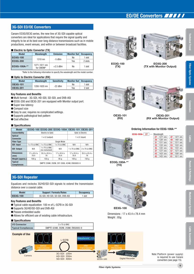
3G-SDI EO/OE Converters
3G-SDI Repeater
Canare EO3G/OE3G series, the new line of 3G-SDI capable optical converters are ideal for applications that require the signal quality and integrity to be at its best over long distance transmissions such as in mobile productions, event venues, and within or between broadcast facilities.
Equalizes and reclocks 3G/HD/SD-SDI signals to extend the transmission distance over a coaxial cable.
■ Electric to Optic Converter (TX)
■ Optic to Electric Converter (RX)
Model Wavelength Emission Monitor Out OccupancyEO3G-100
1310 nm -5 dBmNo 1 slot
EO3G-200 Yes 2 slots
EO3G-100A-** 1271-1611 nm for CWDM* +2.5 dBm No 1 slot
*Refer to the following information to specify the wavelength and the model number.
Model Support Formats/Rates OccupancyEE3G-100 3G-SDI, HD-SDI, SD-SDI, DVB-ASI 1 slot
■ SpecificationsI/O Connector 2 x 75 BNC
Typical Compliances SMPTE 424M, 292M, 259M, EN50083-9
Model Wavelength Sensitivity Monitor Out OccupancyOE3G-101
1200-1620 nm -22 dBmNo 1 slot
OE3G-201 Yes 2 slot
Key Features and Benefits● Multi format - 3G-SDI, HD-SDI, SD-SDI, and DVB-ASI● EO3G-200 and OE3G-201 are equipped with Monitor output port.● Super low-latency● Compact size● Easy to use; requires no complicated settings.● Supports pathological test pattern● Cost effective
Key Features and Benefits● Typical cable equalization: 100 m of L-5CFB in 3G-SDI● Supports 3G/HD/SD-SDI and DVB-ASI● Passes embedded audio● Allows for efficient use of existing cable infrastructure.
■ SpecificationsModel EO3G-100 EO3G-200 EO3G-100A OE3G-101 OE3G-201
Convertibility Electric to Optic Optic to Electric
Optical Connector
1 x LC (output) 1 x LC (input)
Fiber Type Single Mode
SDI Input 1 x 75 BNC 1 x 75 BNC 1 x 75 BNC N/A N/A
SDI Output N/A 1 x 75 BNC(no-reclocked) N/A 1 x 75 BNC 2 x 75 BNC
Dimensions (mm)
17 x 43.4 x 78.4
35.5 x 43.4 x 78
17 x 43.4 x 78.4
17 x 43.4 x 78.4
35.5 x 43.4 x 78
Weight (approx.) 100 g 150 g 95 g 100 g 150 g
Typical Compliances
SMPTE 259M, 292M, 297-2006, 424M, EN50083-9
EO3G-100(TX)
EO3G-200(TX with Monitor Output)
OE3G-101(RX)
EO3G-100A-**(TX)
OE3G-201(RX with Monitor Output)
Note: Platform (power supply) is required to use Canare converters (see page 15).
EE3G-100
Dimensions : 17 x 43.4 x 78.4 mmWeight : 85g
3G-SDI 100mHD-SDI 200mSD-SDI 400m
CameraDigital RecorderEE3G-100
BeforeTransmission
AfterTransmission
AfterReclocking
Example of Use
Ordering Information for EO3G-100A-**
EO3G-100A- 2747 1471 nm49 1491 nm51 1511 nm53 1531 nm55 1551 nm57 1571 nm59 1591 nm61 1611 nm
Wavelength27 1271 nm29 1291 nm31 1311 nm33 1331 nm35 1351 nm37 1371 nm43 1431 nm45 1451 nm
EO/OE Converters
Fiber-Optic Systems
10Fiber-Optic Systems
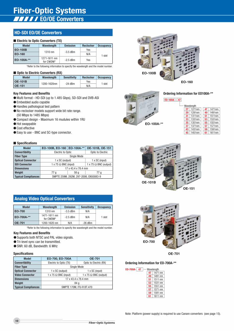
HD-SDI EO/OE Converters
■ Electric to Optic Converters (TX)Model Wavelength Emission Reclocker Occupancy
EO-100B1310 nm -3.5 dBm
Yes
1 slotEO-160 N/A
EO-100A-** 1271-1611 nmfor CWDM* -2.5 dBm Yes
*Refer to the following information to specify the wavelength and the model number.
■ Optic to Electric Converters (RX)Model Wavelength Sensitivity Reclocker Occupancy
OE-101B 1200-1620nm -24 dBm
Yes1 slot
OE-151 N/A
Key Features and Benefits● Multi format - HD-SDI (up to 1.485 Gbps), SD-SDI and DVB-ASI● Embedded audio capable● Handles pathological test pattern● No-reclocker models support wide bit rate range. (50 Mbps to 1485 Mbps)● Compact design - Maximum 16 mudules within 1RU● Hot swappable● Cost effective● Easy to use - BNC and SC-type connector.
EO-100B
EO-160
OE-101B
OE-151
EO-100A-**
■ SpecificationsModel EO-100B, EO-160 EO-100A-** OE-101B, OE-151
Convertibility Electric to Optic Optic to ElectricFiber Type Single ModeOptical Connector 1 x SC (output) 1 x SC (input)SDI Connector 1 x 75 BNC (input) 1 x 75 BNC (output)Dimensions 17 x 43.4 x 78.4 mmWeight 77 g 58 g 77 gTypical Compliances SMPTE 259M, 292M, 297-2006, EN50083-9
Note: Platform (power supply) is required to use Canare converters (see page 15).
Ordering Information for EO100A-**
EO-100A - 47
47 1471nm 49 1491nm 51 1511nm 53 1531nm 55 1551nm 57 1571nm 59 1591nm 61 1611nm
Wavelength27 1271nm 29 1291nm 31 1311nm 33 1331nm 35 1351nm 37 1371nm 43 1431nm 45 1451nm
Analog Video Optical Converters
Model Wavelength Emission Sensitivity OccupancyEO-700 1310 nm -3.5 dBm N/A
1 slotEO-700A-** 1471-1611 nmfor CWDM* -2.5 dBm N/A
OE-701 1200-1620 nm N/A -26 dBm
*Refer to the following information to specify the wavelength and the model number.
Key Features and Benefits● Supports both NTSC and PAL video signals.● Tri-level sync can be transmitted.● SNR: 60 dB, Bandwidth: 6 MHz
SpecificationsModel EO-700, EO-700A OE-701
Convertibility Electric to Optic (TX) Optic to Electric (RX)Fiber Type Single ModeOptical Connector 1 x SC (output) 1 x SC (input)Video Connector 1 x 75 BNC (input) 1 x 75 BNC (output)Dimensions 17 x 43.4 x 78.4 mmWeight 84 gTypical Compliances SMPTE 170M, ITU-R BT.470
EO-700
OE-701
Ordering Information for EO-700A-**
EO-700A- 47 Wavelength47 1471 nm49 1491 nm51 1511 nm53 1531 nm55 1551 nm57 1571 nm59 1591 nm61 1611 nm
EO/OE Converters
11Fiber-Optic Systems
Technical TrendFiber-O
ptic Systems
ConnectorsCables
Panels & Patchbays
Mutichannel System
sCable A
ssemblies
Ordering Information for TRM-540A-**
TRM-540A- 47 Wavelength47 1471 nm49 1491 nm51 1511 nm53 1531 nm55 1551 nm57 1571 nm59 1591 nm61 1611 nm
Ordering Information for EO-500-**
EO-500- 47 Wavelength47 1471 nm49 1491 nm51 1511 nm53 1531 nm55 1551 nm57 1571 nm59 1591 nm61 1611 nm
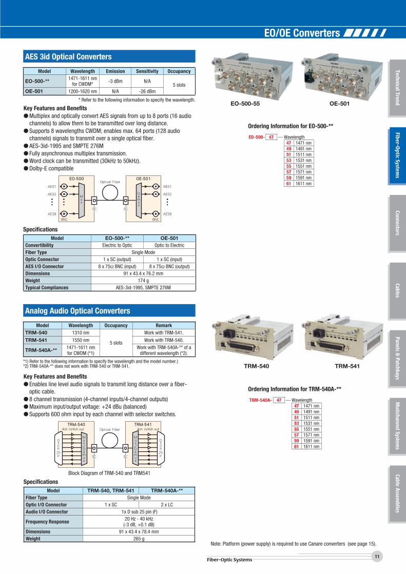
AES 3id Optical Converters
Analog Audio Optical Converters
EO-500-55 OE-501
TRM-540 TRM-541
Key Features and Benefits● Multiplex and optically convert AES signals from up to 8 ports (16 audio
channels) to allow them to be transmitted over long distance.● Supports 8 wavelengths CWDM; enables max. 64 ports (128 audio
channels) signals to transmit over a single optical fiber.● AES-3id-1995 and SMPTE 276M● Fully asynchronous multiplex transmission.● Word clock can be transmitted (30kHz to 50kHz).● Dolby-E compatible
Key Features and Benefits● Enables line level audio signals to transmit long distance over a fiber-
optic cable. ● 8 channel transmission (4-channel inputs/4-channel outputs)● Maximum input/output voltage: +24 dBu (balanced) ● Supports 600 ohm input by each channel with selector switches.
SpecificationsModel EO-500-** OE-501
Convertibility Electric to Optic Optic to ElectricFiber Type Single ModeOptic Connector 1 x SC (output) 1 x SC (input)AES I/O Connector 8 x 75 BNC (input) 8 x 75 BNC (output)Dimensions 91 x 43.4 x 76.2 mmWeight 174 gTypical Compliances AES-3id-1995, SMPTE 276M
SpecificationsModel TRM-540, TRM-541 TRM-540A-**
Fiber Type Single ModeOptic I/O Connector 1 x SC 2 x LCAudio I/O Connector 1x D sub 25 pin (F)
Frequency Response 20 Hz - 40 kHz(-3 dB, +0.1 dB)
Dimensions 91 x 43.4 x 78.4 mmWeight 265 g
Model Wavelength Emission Sensitivity Occupancy
EO-500-** 1471-1611 nmfor CWDM* -3 dBm N/A
5 slotsOE-501 1200-1620 nm N/A -26 dBm
* Refer to the following information to specify the wavelength.
Model Wavelength Occupancy RemarkTRM-540 1310 nm
5 slots
Work with TRM-541.
TRM-541 1550 nm Work with TRM-540.
TRM-540A-** 1471-1611 nmfor CWDM (*1)
Work with TRM-540A-** of adifferent wavelength (*2).
*1) Refer to the following information to specify the wavelength and the model number.)*2) TRM-540A-** does not work with TRM-540 or TRM-541.
EO-500
BNC BNC
AES1
AES2
AES8
Optical FiberOE-501
AES1
AES2
AES8
Mux
Demux
SC SC
TRM-540Optical Fiber 4ch in/4ch out4ch in/4ch out
TRM-541
SC SC
Dsub
25
P
Dsub
25
P
Block Diagram of TRM-540 and TRM541
Note: Platform (power supply) is required to use Canare converters (see page 15).
EO/OE Converters
Fiber-Optic Systems
TRM-300-G31 TRM-300-G55Optical Fiber
RJ45 RJ45SC SC
1000BASE-T 1000BASE-T
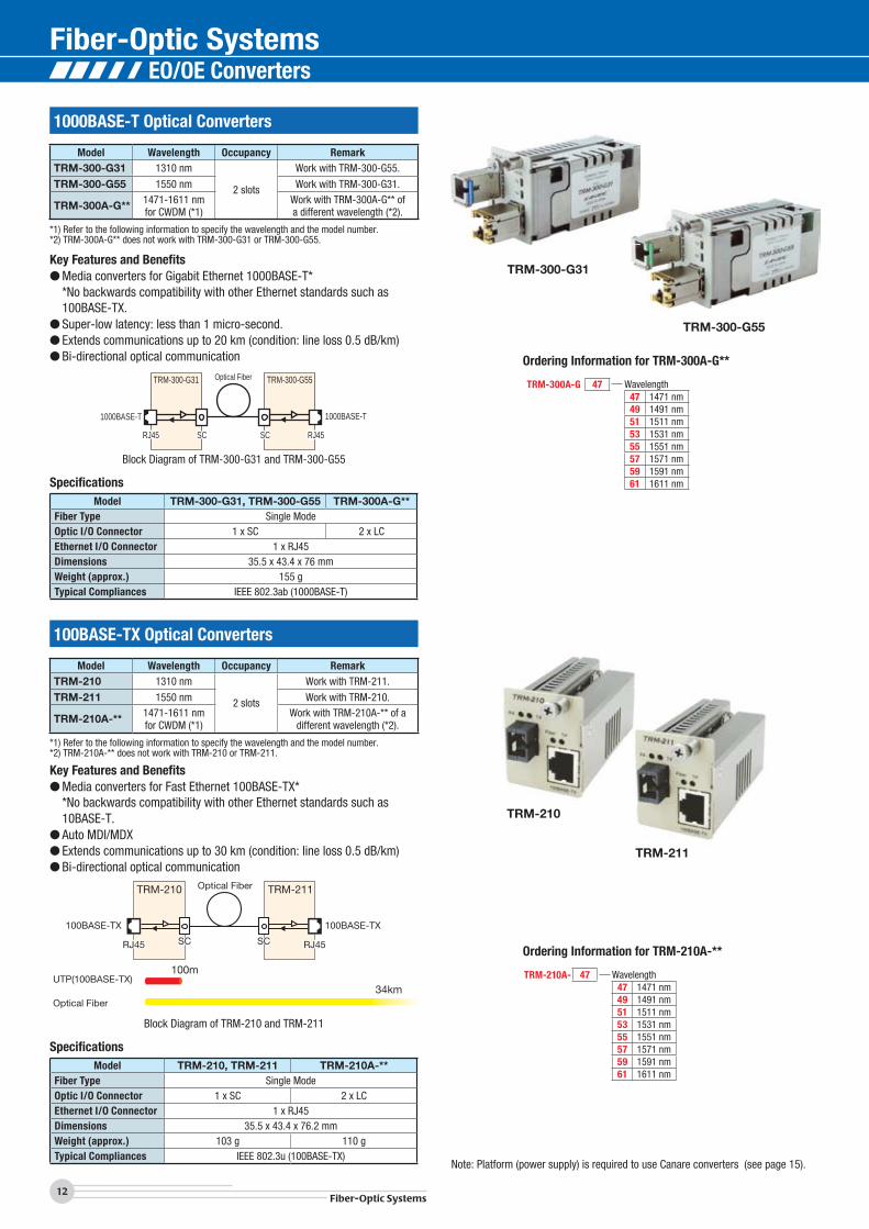
12Fiber-Optic Systems
100BASE-TX Optical Converters
Key Features and Benefits● Media converters for Gigabit Ethernet 1000BASE-T* *No backwards compatibility with other Ethernet standards such as
100BASE-TX.● Super-low latency: less than 1 micro-second.● Extends communications up to 20 km (condition: line loss 0.5 dB/km)● Bi-directional optical communication
Key Features and Benefits● Media converters for Fast Ethernet 100BASE-TX* *No backwards compatibility with other Ethernet standards such as
10BASE-T.● Auto MDI/MDX● Extends communications up to 30 km (condition: line loss 0.5 dB/km)● Bi-directional optical communication
TRM-300-G31
TRM-300-G55
TRM-210
TRM-211
100BASE-TX
Optical Fiber
SC
TRM-210 TRM-211
SC
100BASE-TX
RJ45 RJ45
UTP(100BASE-TX)
Optical Fiber
100m
34km
Block Diagram of TRM-300-G31 and TRM-300-G55
Block Diagram of TRM-210 and TRM-211
Note: Platform (power supply) is required to use Canare converters (see page 15).
Model Wavelength Occupancy RemarkTRM-300-G31 1310 nm
2 slots
Work with TRM-300-G55.
TRM-300-G55 1550 nm Work with TRM-300-G31.
TRM-300A-G** 1471-1611 nmfor CWDM (*1)
Work with TRM-300A-G** ofa different wavelength (*2).
*1) Refer to the following information to specify the wavelength and the model number.*2) TRM-300A-G** does not work with TRM-300-G31 or TRM-300-G55.
Model Wavelength Occupancy RemarkTRM-210 1310 nm
2 slots
Work with TRM-211.
TRM-211 1550 nm Work with TRM-210.
TRM-210A-** 1471-1611 nmfor CWDM (*1)
Work with TRM-210A-** of adifferent wavelength (*2).
*1) Refer to the following information to specify the wavelength and the model number.*2) TRM-210A-** does not work with TRM-210 or TRM-211.
SpecificationsModel TRM-300-G31, TRM-300-G55 TRM-300A-G**
Fiber Type Single ModeOptic I/O Connector 1 x SC 2 x LCEthernet I/O Connector 1 x RJ45Dimensions 35.5 x 43.4 x 76 mmWeight (approx.) 155 gTypical Compliances IEEE 802.3ab (1000BASE-T)
SpecificationsModel TRM-210, TRM-211 TRM-210A-**
Fiber Type Single ModeOptic I/O Connector 1 x SC 2 x LCEthernet I/O Connector 1 x RJ45Dimensions 35.5 x 43.4 x 76.2 mmWeight (approx.) 103 g 110 gTypical Compliances IEEE 802.3u (100BASE-TX)
Ordering Information for TRM-300A-G**
TRM-300A-G 47 Wavelength47 1471 nm49 1491 nm51 1511 nm53 1531 nm55 1551 nm57 1571 nm59 1591 nm61 1611 nm
Ordering Information for TRM-210A-**
TRM-210A- 47 Wavelength47 1471 nm49 1491 nm51 1511 nm53 1531 nm55 1551 nm57 1571 nm59 1591 nm61 1611 nm
1000BASE-T Optical Converters
EO/OE Converters
More Converters
13Fiber-Optic Systems
Technical TrendFiber-O
ptic Systems
ConnectorsCables
Panels & Patchbays
Mutichannel System
sCable A
ssemblies
RS-422/RS-232 Optical Converters
Multiplex and optically convert analog video, stereo audio, RS-422, and relay signals to transmit long distance over a fiber-optic cable.
Multiplex and optically convert HD-SDI and RS-485 signal to transmit long distance over a fiber-optic cable. Suited for HD surveillance camera system.
Multiplex and optically convert 7 of each input/output relay signal and RS-422/232 signals to transmit long distance over a fiber-optic cable.
Key Features and Benefits● TIA-422, SMPTE 207M, RS-232● Usable in a case of RS-422 <=> RS-232● Extends communications up to 30 km (condition: line loss 0.5 dB/km)● Bi-directional optical communication
TRM-220
TRM-221Optical Fiber
RS-422RS-232
RS-422RS-232
Dsub 9pin Dsub 9pinSC
TRM-220 TRM-221
SC
Block Diagram of TRM-220 and TRM-221
Note: Platform (power supply) is required to use Canare converters (see page 15).
Note: Platform (power supply) is required to use Canare converters (see page 15).
Model Wavelength Occupancy RemarkTRM-220 1310 nm
3 slots
Work with TRM-221.
TRM-221 1550 nm Work with TRM-220.
TRM-220A-** 1471-1611 nmfor CWDM (*1)
Work with TRM-220A-** of adifferent wavelength (*2).
*1) Refer to the following information to specify the wavelength and the model number.*2) TRM-220A-** does not work with TRM-220 or TRM-221.
SpecificationsModel TRM-220, TRM-221 TRM-220A-**
Fiber Type Single ModeOptic I/O Connector 1 x SC 2 x LCSerial I/O Port 1 x Dsub 9 pin (F)Max. Data Rate RS-422: 10 Mbps, RS-232: 1 MbpsDimensions 54 x 43.4 x 76.2 mmWeight (approx.) 110 g 120 gTypical Compliances TIA-422, SMPTE 207M, RS-232C
Ordering Information for TRM-220A-**
TRM-220A- 47 Wavelength47 1471 nm49 1491 nm51 1511 nm53 1531 nm55 1551 nm57 1571 nm59 1591 nm61 1611 nm
Model OccupancyTRM-400
3 slotsTRM-401
Model OccupancyTRM-100
3 slotsTRM-101
Model OccupancyTRM-230
3 slotsTRM-231
TRM-400 TRM-401Optical Fiber
SC SC
AnalogVideo
RS-422
Relay
Audio(unbalanced)
AnalogVideo
RS-422
Relay
Audio(unbalanced)
TRM-230 TRM-231Optical Fiber
SC SC
7 ch Relay Input
RS-232RS-422
RS-232RS-422
7 ch Relay Output7 ch Relay Input7 ch Relay Output
LC LCLC LC
HD-SDI
RS-485
HD-SDI
TRM-100 TRM-101Optical Fiber
RS-485
EO/OE Converters
Fiber-Optic Systems
14Fiber-Optic Systems
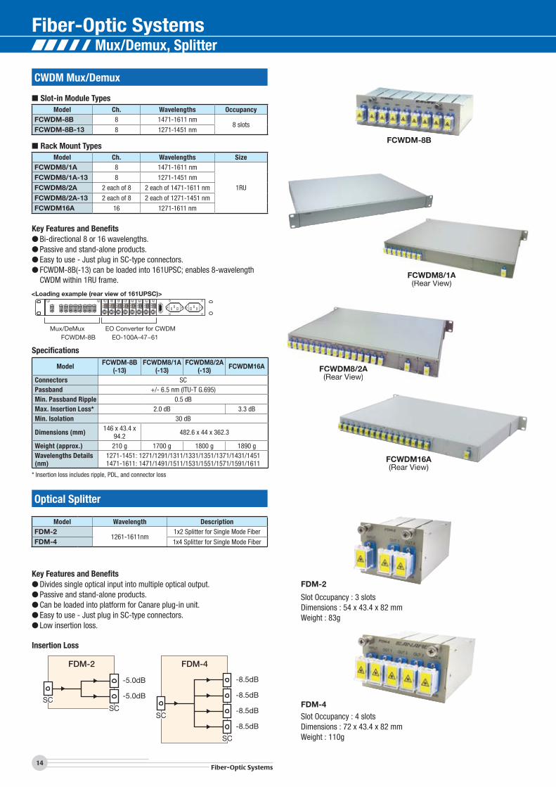
CWDM Mux/Demux
Model Ch. Wavelengths OccupancyFCWDM-8B 8 1471-1611 nm
8 slotsFCWDM-8B-13 8 1271-1451 nm
Model Ch. Wavelengths SizeFCWDM8/1A 8 1471-1611 nm
1RU
FCWDM8/1A-13 8 1271-1451 nm
FCWDM8/2A 2 each of 8 2 each of 1471-1611 nm
FCWDM8/2A-13 2 each of 8 2 each of 1271-1451 nm
FCWDM16A 16 1271-1611 nm
Key Features and Benefits● Bi-directional 8 or 16 wavelengths.● Passive and stand-alone products.● Easy to use - Just plug in SC-type connectors.● FCWDM-8B(-13) can be loaded into 161UPSC; enables 8-wavelength
CWDM within 1RU frame.
Specifications
Model FCWDM-8B(-13)
FCWDM8/1A(-13)
FCWDM8/2A(-13) FCWDM16A
Connectors SCPassband +/- 6.5 nm (ITU-T G.695)Min. Passband Ripple 0.5 dBMax. Insertion Loss* 2.0 dB 3.3 dBMin. Isolation 30 dB
Dimensions (mm) 146 x 43.4 x 94.2 482.6 x 44 x 362.3
Weight (approx.) 210 g 1700 g 1800 g 1890 g Wavelengths Details(nm)
1271-1451: 1271/1291/1311/1331/1351/1371/1431/14511471-1611: 1471/1491/1511/1531/1551/1571/1591/1611
* Insertion loss includes ripple, PDL, and connector loss
FCWDM-8B
FCWDM8/1A(Rear View)
FCWDM8/2A(Rear View)
Slot Occupancy : 3 slotsDimensions : 54 x 43.4 x 82 mmWeight : 83g
FDM-2
Slot Occupancy : 4 slotsDimensions : 72 x 43.4 x 82 mmWeight : 110g
FDM-4
Optical Splitter
Model Wavelength DescriptionFDM-2
1261-1611nm1x2 Splitter for Single Mode Fiber
FDM-4 1x4 Splitter for Single Mode Fiber
Key Features and Benefits● Divides single optical input into multiple optical output.● Passive and stand-alone products.● Can be loaded into platform for Canare plug-in unit.● Easy to use - Just plug in SC-type connectors.● Low insertion loss.
FDM-2
SCSC
-5.0dB
-5.0dB
FDM-4
SC
SC
-8.5dB
-8.5dB
-8.5dB
-8.5dB
Insertion Loss
FCWDM16A(Rear View)
FCWDM-8BMux/DeMux EO Converter for CWDM
EO-100A-47~61
■ Slot-in Module Types
■ Rack Mount Types
FCWDM8/1A(R Vi )
FCWDM8/2A(Rear View)
Mux/Demux, Splitter
15Fiber-Optic Systems
Technical TrendFiber-O
ptic Systems
ConnectorsCables
Panels & Patchbays
Mutichannel System
sCable A
ssemblies
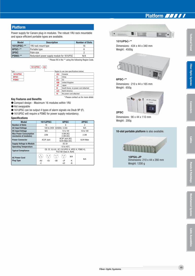
PlatformPower supply for Canare plug-in modules. The robust 1RU rack mountable and space efficient portable types are available.
Model Description Number of Slots161UPSC-** 1RU rack mount type 166PSC-** Portable type 62PSC Palm size 2PSM2-** Redundant power supply module for 161UPSC N/A
* Please fill in the ** using the following Region Code.
Key Features and Benefits● Compact design - Maximum 16 modules within 1RU● Hot swappable● 161UPSC can be output 4 types of alarm signals via Dsub 9P (F).● 161UPSC will require a PSM2 for power supply redundancy.
Dimensions : 434 x 44 x 340 mmWeight : 4500g
161UPSC-**
Dimensions : 210 x 44 x 165 mmWeight : 650g
6PSC-**
Dimensions : 90 x 44 x 110 mmWeight : 200g
2PSC
g
ions : 990 x 444 x 11110 mmSpecificationsModel 161UPSC 6PSC 2PSC
Number of Slots 16 6 2AC Input Voltage 100 to 240V 50/60Hz 0.35A N/ADC Input Voltage N/A 10 to 18V 10 to 18VMax Power Consumption(exclusive of modules) 22W 4.5W (AC)
2.2W (DC) 2.2W
Power Connector AC3P Jack AC3P Jack (AC)XLR4 Male (DC) XLR4 Male
Supply Voltage to Module DC 5V Operating Temperature -10 to 40˚C
Typical Compliance CB, CE, UL/cUL, KC (161UPSC-K, 6PSC-K, PSM2-K),FCC15B Class A, RoHS
AC Power CordPlug Type
N/AN/A
-AU -EU -GB -JP -K-C -UC -N
161UPSC - AU
Region to use (see specifications below)AU OceaniaC ChinaEU EUGB United KingdomJP JapanK South Korea, no power cord attachedUC North AmericaN No power cord attached
* Please contact us for more detail.
Type161UPSC6PSCPSM2
10PSA-JPDimensions: 210 x 44 x 280 mmWeight: 1200 g
10-slot portable platform is also available.
161UPSC **
Platform
Fiber-Optic Systems
16Fiber-Optic Systems
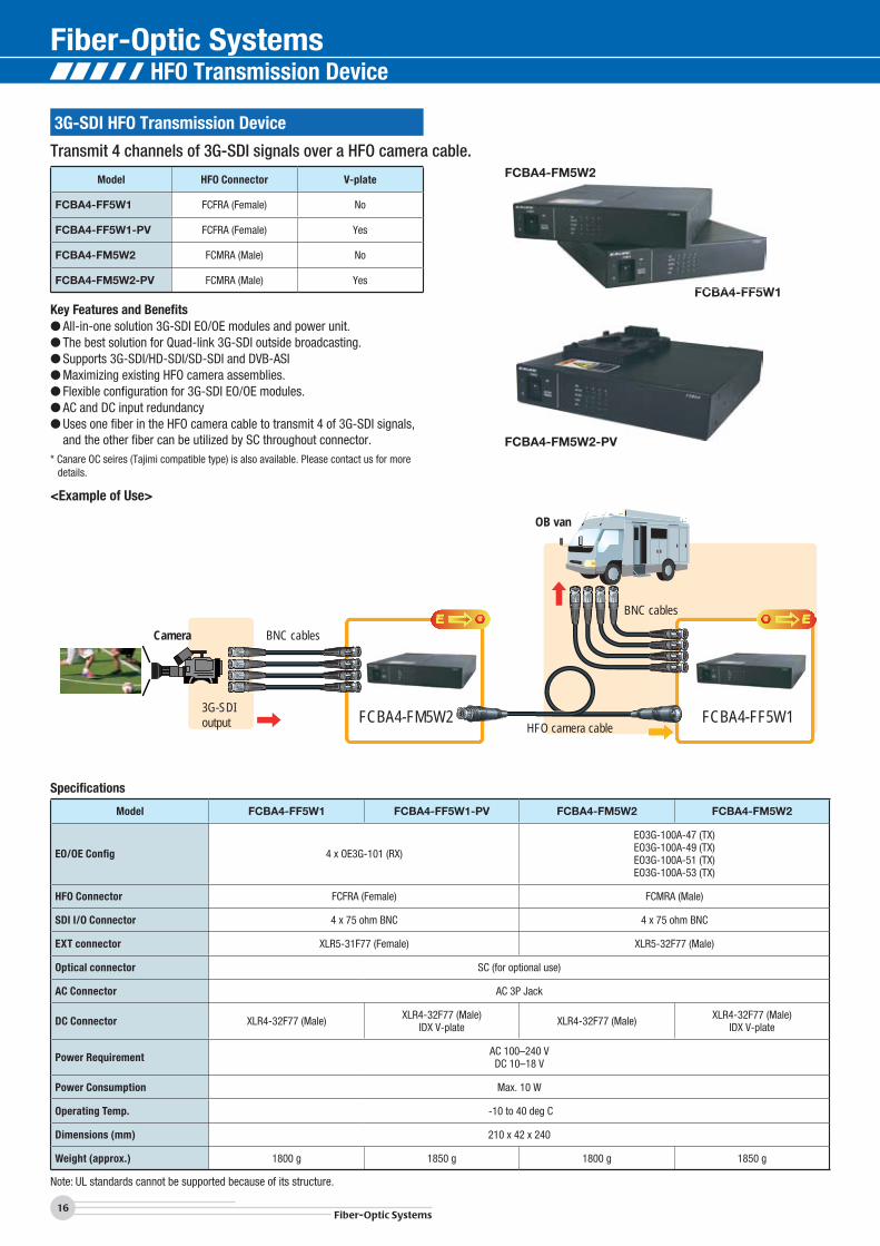
3G-SDI HFO Transmission Device
Transmit 4 channels of 3G-SDI signals over a HFO camera cable.
Model HFO Connector V-plate
FCBA4-FF5W1 FCFRA (Female) No
FCBA4-FF5W1-PV FCFRA (Female) Yes
FCBA4-FM5W2 FCMRA (Male) No
FCBA4-FM5W2-PV FCMRA (Male) Yes
Key Features and Benefits● All-in-one solution 3G-SDI EO/OE modules and power unit.● The best solution for Quad-link 3G-SDI outside broadcasting.● Supports 3G-SDI/HD-SDI/SD-SDI and DVB-ASI● Maximizing existing HFO camera assemblies.● Flexible configuration for 3G-SDI EO/OE modules.● AC and DC input redundancy● Uses one fiber in the HFO camera cable to transmit 4 of 3G-SDI signals,
and the other fiber can be utilized by SC throughout connector.* Canare OC seires (Tajimi compatible type) is also available. Please contact us for more
details.
Specifications
Model FCBA4-FF5W1 FCBA4-FF5W1-PV FCBA4-FM5W2 FCBA4-FM5W2
EO/OE Config 4 x OE3G-101 (RX)
EO3G-100A-47 (TX)EO3G-100A-49 (TX)EO3G-100A-51 (TX)EO3G-100A-53 (TX)
HFO Connector FCFRA (Female) FCMRA (Male)
SDI I/O Connector 4 x 75 ohm BNC 4 x 75 ohm BNC
EXT connector XLR5-31F77 (Female) XLR5-32F77 (Male)
Optical connector SC (for optional use)
AC Connector AC 3P Jack
DC Connector XLR4-32F77 (Male) XLR4-32F77 (Male)IDX V-plate XLR4-32F77 (Male) XLR4-32F77 (Male)
IDX V-plate
Power Requirement AC 100–240 VDC 10–18 V
Power Consumption Max. 10 W
Operating Temp. -10 to 40 deg C
Dimensions (mm) 210 x 42 x 240
Weight (approx.) 1800 g 1850 g 1800 g 1850 g
Note: UL standards cannot be supported because of its structure.
<Example of Use>
OB van
Camera BNC cables
HFO camera cable
BNC cables
3G-SDIoutput FCBA4-FF5W1FCBA4-FM5W2
FCBA4-FM5W2
FCBA4-FF5W1
FCBA4-FM5W2-PV
CBA4 FM5W2
FCBA4 FF5W
HFO Transmission Device
17Fiber-Optic Systems
Technical TrendFiber-O
ptic Systems
ConnectorsCables
Panels & Patchbays
Mutichannel System
sCable A
ssemblies
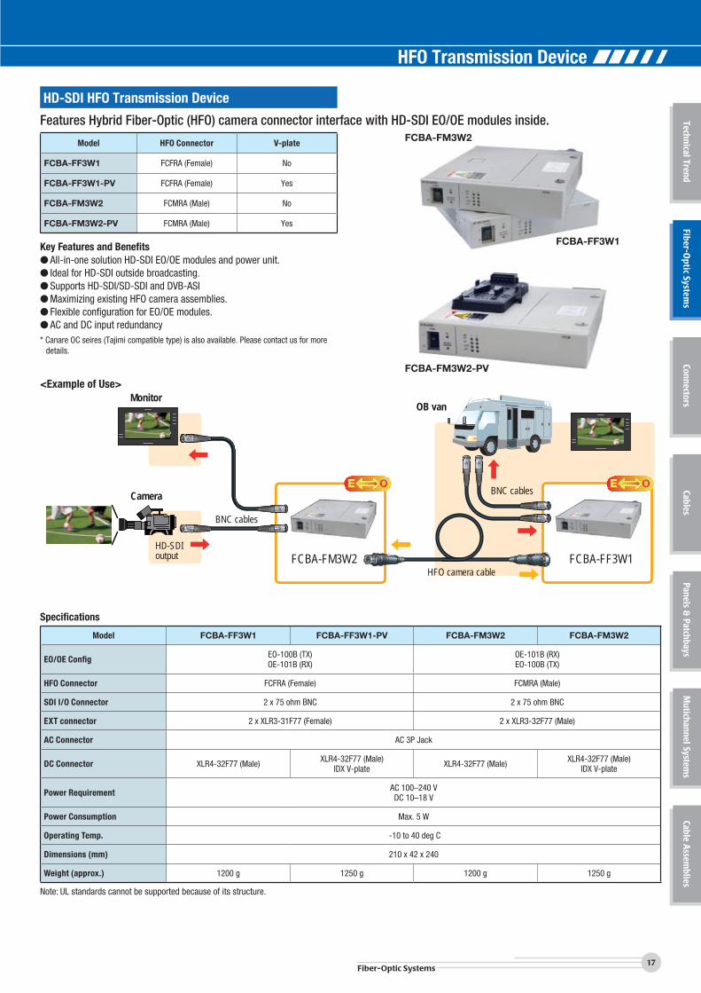
HD-SDI HFO Transmission Device
Features Hybrid Fiber-Optic (HFO) camera connector interface with HD-SDI EO/OE modules inside.
Model HFO Connector V-plate
FCBA-FF3W1 FCFRA (Female) No
FCBA-FF3W1-PV FCFRA (Female) Yes
FCBA-FM3W2 FCMRA (Male) No
FCBA-FM3W2-PV FCMRA (Male) Yes
Key Features and Benefits● All-in-one solution HD-SDI EO/OE modules and power unit.● Ideal for HD-SDI outside broadcasting.● Supports HD-SDI/SD-SDI and DVB-ASI● Maximizing existing HFO camera assemblies.● Flexible configuration for EO/OE modules.● AC and DC input redundancy* Canare OC seires (Tajimi compatible type) is also available. Please contact us for more
details.
Specifications
Model FCBA-FF3W1 FCBA-FF3W1-PV FCBA-FM3W2 FCBA-FM3W2
EO/OE Config EO-100B (TX)OE-101B (RX)
OE-101B (RX)EO-100B (TX)
HFO Connector FCFRA (Female) FCMRA (Male)
SDI I/O Connector 2 x 75 ohm BNC 2 x 75 ohm BNC
EXT connector 2 x XLR3-31F77 (Female) 2 x XLR3-32F77 (Male)
AC Connector AC 3P Jack
DC Connector XLR4-32F77 (Male) XLR4-32F77 (Male)IDX V-plate XLR4-32F77 (Male) XLR4-32F77 (Male)
IDX V-plate
Power Requirement AC 100–240 VDC 10–18 V
Power Consumption Max. 5 W
Operating Temp. -10 to 40 deg C
Dimensions (mm) 210 x 42 x 240
Weight (approx.) 1200 g 1250 g 1200 g 1250 g
Note: UL standards cannot be supported because of its structure.
<Example of Use>
FCBA-FM3W2
FCBA-FF3W1
FCBA-FM3W2-PV
OB van
Camera
BNC cables
Monitor
HFO camera cable
HD-SDIoutput FCBA-FM3W2 FCBA-FF3W1
BNC cables
HFO Transmission Device
Fiber-Optic Systems
18Fiber-Optic Systems
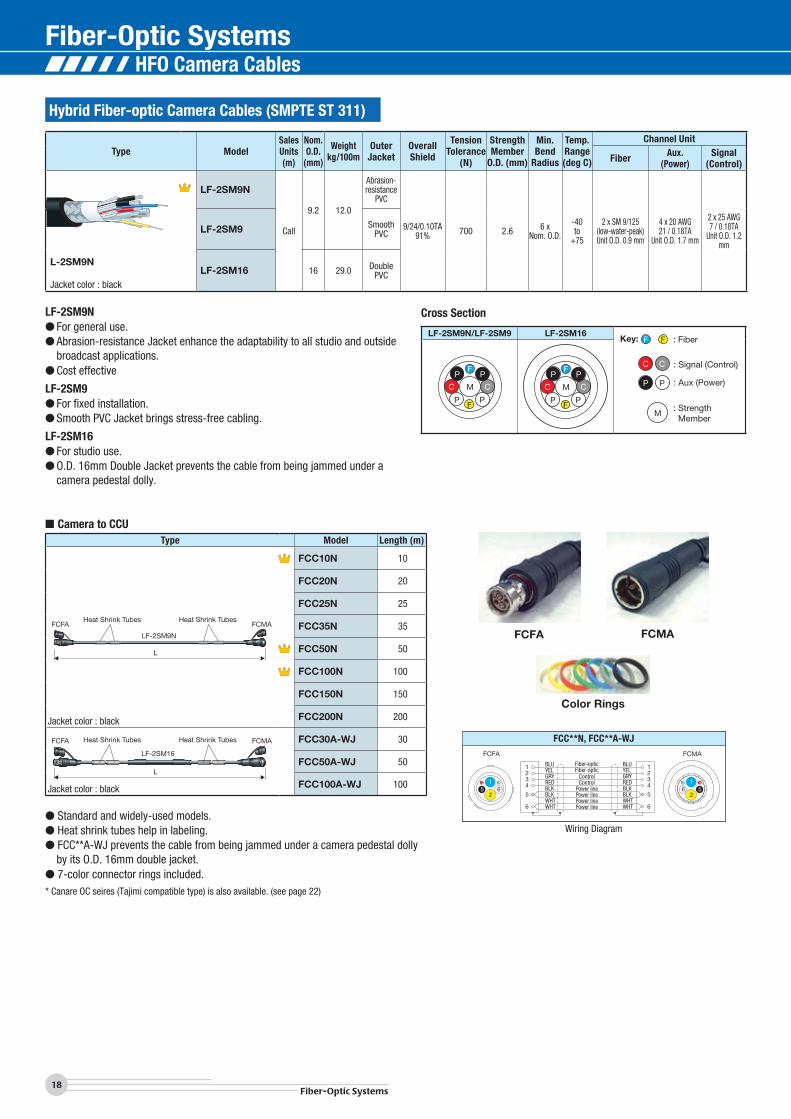
Hybrid Fiber-optic Camera Cables (SMPTE ST 311)
Type ModelSalesUnits(m)
Nom.O.D.
(mm)
Weightkg/100m
OuterJacket
Overall Shield
TensionTolerance
(N)
StrengthMember
O.D. (mm)
Min.Bend
Radius
Temp.Range(deg C)
Channel Unit
Fiber Aux.(Power)
Signal(Control)
L-2SM9N
Jacket color : black
LF-2SM9N
Call
9.2 12.0
Abrasion-resistance
PVC
9/24/0.10TA91% 700 2.6 6 x
Nom. O.D.
-40 to
+75
2 x SM 9/125(low-water-peak)Unit O.D. 0.9 mm
4 x 20 AWG21 / 0.18TA
Unit O.D. 1.7 mm
2 x 25 AWG7 / 0.18TA
Unit O.D. 1.2 mm
LF-2SM9 SmoothPVC
LF-2SM16 16 29.0 DoublePVC
LF-2SM9N ● For general use.● Abrasion-resistance Jacket enhance the adaptability to all studio and outside
broadcast applications.● Cost effective
LF-2SM9● For fixed installation.● Smooth PVC Jacket brings stress-free cabling.
LF-2SM16● For studio use.● O.D. 16mm Double Jacket prevents the cable from being jammed under a
camera pedestal dolly.
Cross Section
LF-2SM9N/LF-2SM9 LF-2SM16F F
C C
P P
M
Key: : Fiber
: Signal (Control)
: Aux (Power)
: Strength Member
FP
C
P
P
C
PF
M
FP
C
P
P
C
PF
M
Type Model Length (m)
L
FCFA FCMA
LF-2SM9N
Heat Shrink Tubes Heat Shrink Tubes
Jacket color : black
FCC10N 10
FCC20N 20
FCC25N 25
FCC35N 35
FCC50N 50
FCC100N 100
FCC150N 150
FCC200N 200
L
FCFA FCMA
LF-2SM16
Heat Shrink Tubes Heat Shrink Tubes
Jacket color : black
FCC30A-WJ 30
FCC50A-WJ 50
FCC100A-WJ 100
● Standard and widely-used models. ● Heat shrink tubes help in labeling.● FCC**A-WJ prevents the cable from being jammed under a camera pedestal dolly
by its O.D. 16mm double jacket.● 7-color connector rings included.* Canare OC seires (Tajimi compatible type) is also available. (see page 22)
FCFA FCMA
Color Rings
■ Camera to CCU
Power linePower linePower linePower line
ControlControl
Fiber-opticFiber-optic
BLUYELGRYREDBLKBLKWHTWHT
BLUYELGRYREDBLKBLKWHTWHT
52
1 3
6
6
432
5
1
4
1
51
26
234
6
5
FCFA FCMA
3 4
FCC**N, FCC**A-WJ
Wiring Diagram
HFO Camera Cables
19Fiber-Optic Systems
Technical TrendFiber-O
ptic Systems
ConnectorsCables
Panels & Patchbays
Mutichannel System
sCable A
ssemblies
Slim Hybrid Fiber-optic Camera Cable
Type ModelSalesUnits(m)
Nom.O.D.
(mm)
Weightkg/100m
OuterJacket
Overall Shield
TensionTolerance
(N)
StrengthMember
O.D. (mm)
Min.Bend
Radius
Temp.Range(deg C)
Channel Unit
Fiber Aux.(Power)
Signal(Control)
Jacket color : black
LF-2SM7N Call 7.1 7.3 Abrasion-resistance
PVC
8/24/0.10TA91% 300 1.4 6 x
Nom. O.D.
-40 to
+75
2 x SM 9/125(low-water-peak)Unit O.D. 0.9 mm
2 x 20 AWG21 / 0.18TA
Unit O.D. 1.7 mm
2 x 25 AWG7 / 0.18A
Unit O.D. 1.2 mm
LF-2SM7N● O.D. 7 mm of slim profile and approx. 40% lighter than LF-2SM9N.● Best fit for mobile applications.● The power transmission distance is approx. twice as long as the previous model LF-2SM7R.Note: The power transmission distance is shorter than typical HFO camera cables (approx. 50% of LF-2SM9N).
Please contact us for more information.
*Multichannel cables, LF-2SM7N-3P and LF-2SM7N-5P, are also available.
Cross Section
LF-2SM7N F F
C C
P P
M
Key: : Fiber
: Signal (Control)
: Aux (Power)
: Strength Member
C
P
P
C
F
F
MC
Type Model Length (m)
L
FCF7A FCM7A
LF-2SM7T
Heat Shrink Tubes Heat Shrink Tubes
LF-2SM7N
Jacket color: black
FCC10-7N 10
FCC20-7N 20
FCC30-7N 30
FCC50-7N 50
FCC100-7N 100
L
FCF7A FCM7A
LF-2SM7N-3P
Heat Shrink Tubes Heat Shrink Tubes
Jacket color: black
F3-FCC10-7N 10
F3-FCC20-7N 20
F3-FCC30-7N 30
F3-FCC50-7N 50
F3-FCC100-7N 100
L
FCF7A FCM7A
LF-2SM7N-5P
Heat Shrink Tubes Heat Shrink Tubes
Jacket color: black
F5-FCC10-7N 10
F5-FCC20-7N 20
F5-FCC30-7N 30
F5-FCC50-7N 50
F5-FCC100-7N 100
● Equipped with slim and lightweight cable.● FCC100-7N is approx. 5 kg lighter than typical 100m HFO camera cable as
FCC100N.● Heat shrink tubes help in labeling.● 7-color connector rings included.Note: The power transmission distance of FCC**-7N is approx. half of that of the FCC**N.* Canare OC seires (Tajimi compatible type) is also available. (see page 22)
FCF7A FCM7A
Color Rings
■ Camera to CCU
FCC**-7N
4 4
Power line
Power line
ControlControl
Fiber-opticFiber-optic
YELBLUREDCLR
BLK
WHT
YELBLUREDCLR
BLK
WHT
52
16
6
432
5
1
3
1
51
26
234
6
5
FCF7A FCM7A
3
FCC**-7N, F3-FCC**-7N, F5-FCC**-7N
Wiring Diagram
F5-FCC10-7N
HFO Camera Cables
Fiber-Optic Systems
20Fiber-Optic Systems
Type Model Length (m)
Jacket color : black, deep red, deep green
FCC10-9T 10FCC20-9T 20FCC25-9T 25FCC35-9T 35FCC50-9T 50FCC100-9T 100FCC150-9T 150FCC200-9T 200
Jacket color: black
FCC10-7T 10
FCC20-7T 20
FCC30-7T 30
FCC50-7T 50
FCC100-7T 100
● Tough & Flexible cable● Fit for mobile applications in harsh environments.● Heat shrink tubes help in labeling.● 7-color connector rings included.Note: The power transmission distance of FCC**-7T is
quite shorter than typical HFO camera cables.* Canare OC seires (Tajimi compatible type) is also available. Please contact us for more details.
FCC**-7TFCC**-7T
■ Camera to CCU
Tough & Flexible HFO Camera Cable
Type ModelSalesUnits(m)
Nom.O.D.
(mm)
Weightkg/100m
OuterJacket
Overall Shield
TensionTolerance
(N)
StrengthMember
O.D.
Min.Bend
Radius
Temp.Range(deg C)
Channel Unit
Fiber Aux.(Power)
Signal(Control)
Jacket color : black, deep red, deep green
LF-2SM9T Call 9.2 9.8 TPU+
PVCN/A 1500
1.8 mm +
Tensile strength
fiber
Equal toNom. O.D.
-40 to
+75
2 x SM 9/125(low-water-peak)Unit O.D. 0.9 mm
4 x 20 AWG102 / 0.08A
Unit O.D 1.75 mm
2 x 25 AWG24 / 0.08A
Unit O.D 1.2 mm
Jacket color : black
LF-2SM7T Call 7.1 5.5 TPU+
PVCN/A 1000
0.63 mm +
Tensile strength
fiber
Equal toNom. O.D.
-40 to
+75
2 x SM 9/125(low-water-peak)Unit O.D. 1.7 mm
2 x 23 AWG60 / 0.08A
Unit O.D. 1.4 mm
2 x 26 AWG30 / 0.08A
Unit O.D. 1.1 mm
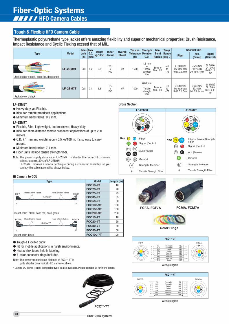
LF-2SM9T● Heavy-duty yet Flexible.● Ideal for remote broadcast applications.● Minimum bend radius: 9.2 mm.
LF-2SM7T● Flexible, Slim, Lightweight, and moreover, Heavy-duty.● Ideal for short-distance remote broadcast applications of up to 200
meters.● O.D. 7.1 mm and weighing only 5.5 kg/100 m, it’s so easy to carry
around.● Minimum bend radius: 7.1 mm.● Fiber units include tensile strength fiber.
Note: The power supply distance of LF-2SM7T is shorter than other HFO camera cables. (approx. 30% of LF-2SM9N)
LF-2SM7T requires a special technique during a connector assembly, so you can buy the cable assemblies shown below.
Cross Section
LF-2SM9T LF-2SM7T
P1
F2 P3P4 C2
C1F1 P2
P1M S1
S2
#
##
#
#
#P1
F2
S
C2
F1
P2
M
C1
## #
C2
F2F1
P1 P2
P3 P4
M
Key: : Fiber
: Signal (Control)
: Aux (Power)
: Ground
: Strength Member
: Tensile Strength Fiber
C1
S1 S2
#
C2
F2F1
P1
S
P2
M
Key: : Fiber + Tensile Strength Fiber
: Signal (Control)
: Aux (Power)
: Ground
: Strength Member
C1
: Tensile Strength Fiber #
FCFA, FCF7A FCMA, FCM7A
Color Rings
4 4
Power linePower line
Ground GRNGRN
ControlControl
Fiber-opticFiber-optic
YELBLUREDCLRBLKWHT
YELBLUREDCLRBLKWHT
52
16
6
432
5
1
3
1
51
26
234
65
FCF7A FCM7A
3
FCC**-7T
52
163
51
26
FCFA FCMA
3 44
Power linePower linePower linePower line
ControlControl
Fiber-opticFiber-optic
YELBLUREDGRNBLKBLKWHTWHT
YELBLUREDGRNBLKBLKWHTWHT
GroundCLR CLR6
432
5
1 1234
6
5
FCC**-9T
Wiring Diagram
Wiring Diagram
Thermoplastic polyurethane type jacket offers amazing flexibility and superior mechanical properties; Crush Resistance, Impact Resistance and Cyclic Flexing exceed that of MIL.
L
FCF7A FCM7A
LF-2SM7T
Heat Shrink Tubes Heat Shrink Tubes
L
FCFA FCMA
LF-2SM9N
Heat Shrink Tubes Heat Shrink Tubes
LF-2SM9T
HFO Camera Cables
21Fiber-Optic Systems
Technical TrendFiber-O
ptic Systems
ConnectorsCables
Panels & Patchbays
Mutichannel System
sCable A
ssemblies
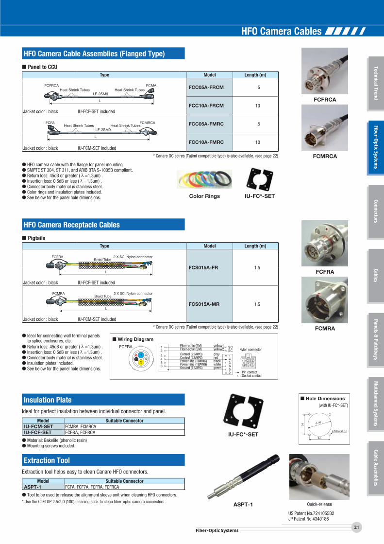
HFO Camera Cable Assemblies (Flanged Type)
HFO Camera Receptacle Cables
Type Model Length (m)
L
FCFRCA FCMA
LF-2SM9Heat Shrink Tubes Heat Shrink Tubes
FCC05A-FRCM 5
Jacket color : black IU-FCF-SET included FCC10A-FRCM 10
L
FCFA FCMRCA
LF-2SM9Heat Shrink Tubes Heat Shrink Tubes FCC05A-FMRC 5
Jacket color : black IU-FCM-SET included FCC10A-FMRC 10
* Canare OC seires (Tajimi compatible type) is also available. (see page 22)
● HFO camera cable with the flange for panel mounting.● SMPTE ST 304, ST 311, and ARIB BTA S-1005B compliant.● Return loss: 45dB or greater ( =1.3μm) .● Insertion loss: 0.5dB or less ( =1.3μm) .● Connector body material is stainless steel.● Color rings and insulation plates included.● See below for the panel hole dimensions.
Type Model Length (m)
L
FCFRA 2 X SC, Nylon connectorBraid Tube
FCS015A-FR 1.5
Jacket color : black IU-FCF-SET included
L
FCMRA 2 X SC, Nylon connectorBraid Tube
FCS015A-MR 1.5
Jacket color : black IU-FCM-SET included
* Canare OC seires (Tajimi compatible type) is also available. (see page 22)
● Ideal for connecting wall terminal panels to splice enclosures, etc.
● Return loss: 45dB or greater ( =1.3μm) .● Insertion loss: 0.5dB or less ( =1.3μm) .● Connector body material is stainless steel.● Insulation plates included.● See below for the panel hole dimensions.
FCFRCA
FCFRA
FCMRCA
FCMRA
∅ 40
4-M3 or ∅ 3.2
34
34
■ Hole Dimensions(with IU-FC*-SET)
Color Rings IU-FC*-SET
FCFRA Fiber-optic (SM) yellow1Fiber-optic (SM) yellow2
Power line (18AWG) blackPower line (18AWG) white
Nylon connectorControl (22AWG) grayControl (22AWG) red65
526
4 314
12
3
56546
2
SC
: Pin contact : Socket contact
SC
2
14 313
Ground (18AWG) green
■ Wiring Diagram
Quick-releaseASPT-1
IU-FC*-SET
US Patent No.7241055B2JP Patent No.4340186
Model Suitable ConnectorIU-FCM-SET FCMRA, FCMRCAIU-FCF-SET FCFRA, FCFRCA
● Material: Bakelite (phenolic resin)● Mounting screws included.
Model Suitable ConnectorASPT-1 FCFA, FCF7A, FCFRA, FCFRCA
● Tool to be used to release the alignment sleeve unit when cleaning HFO connectors.* Use the CLETOP 2.5/2.0 (100) cleaning stick to clean fiber-optic camera connectors.
Insulation Plate
Extraction Tool
Ideal for perfect insulation between individual connector and panel.
Extraction tool helps easy to clean Canare HFO connectors.
■ Panel to CCU
■ Pigtails
HFO Camera Cables
Fiber-Optic Systems
22Fiber-Optic Systems
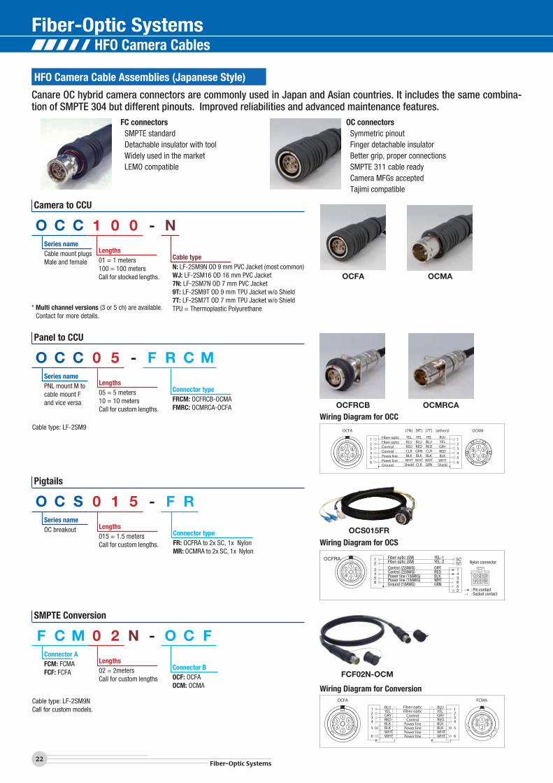
HFO Camera Cable Assemblies (Japanese Style)
Canare OC hybrid camera connectors are commonly used in Japan and Asian countries. It includes the same combina-tion of SMPTE 304 but different pinouts. Improved reliabilities and advanced maintenance features.
FC connectors SMPTE standard Detachable insulator with tool Widely used in the market LEMO compatible
OC connectors Symmetric pinout Finger detachable insulator Better grip, proper connections SMPTE 311 cable ready Camera MFGs accepted Tajimi compatible
* Multi channel versions (3 or 5 ch) are available. Contact for more details.
Cable type: LF-2SM9
Cable type: LF-2SM9NCall for custom models.
FCF02N-OCM
OCFA
OCFRCB OCMRCA
OCS015FR
OCMA
Wiring Diagram for OCC
Wiring Diagram for OCS
Wiring Diagram for Conversion
Power linePower linePower linePower line
ControlControl
Fiber-opticFiber-optic
BLUYELGRYREDBLKBLKWHTWHT
BLUYELGRYREDBLKBLKWHTWHT6
432
5
1 1234
6
5
OCFA FCMA
5
3
1
24
65
3
2
16
4
Power linePower lineGround GRNCLR
ControlControl
Fiber-opticFiber-optic
YELBLUREDGRNBLK
WHT
YELBLUREDCLRBLK
WHT6
432
5
1 1234
65
OCFA OCMA
Shield
YELBLU
GRYREDBLK
WHTShield
YELBLUREDCLRBLK
WHT
[7N] [9T] [7T] [others]
53
1
24
63
51
2
64
OCFRA Fiber-optic (SM) YEL-1Fiber-optic (SM) YEL-2
Power line (18AWG) BLKPower line (18AWG) WHT
Nylon connectorControl (22AWG) GRYControl (22AWG) RED
56
4
12
3
56546
2
SC
: Pin contact : Socket contact
SC
2
14 313
Ground (18AWG) GRN
53
1
24
6
Camera to CCU
Panel to CCU
Pigtails
SMPTE Conversion
Series nameCable mount plugsMale and female
Series namePNL mount M tocable mount Fand vice versa
Series nameOC breakout
Connector AFCM: FCMAFCF: FCFA
Lengths01 = 1 meters100 = 100 metersCall for stocked lengths.
Lengths05 = 5 meters10 = 10 metersCall for custom lengths.
Lengths015 = 1.5 metersCall for custom lengths.
Lengths02 = 2metersCall for custom lengths
Cable typeN: LF-2SM9N OD 9 mm PVC Jacket (most common)WJ: LF-2SM16 OD 16 mm PVC Jacket7N: LF-2SM7N OD 7 mm PVC Jacket9T: LF-2SM9T OD 9 mm TPU Jacket w/o Shield7T: LF-2SM7T OD 7 mm TPU Jacket w/o ShieldTPU = Thermoplastic Polyurethane
Connector typeFRCM: OCFRCB-OCMAFMRC: OCMRCA-OCFA
Connector typeFR: OCFRA to 2x SC, 1x NylonMR: OCMRA to 2x SC, 1x Nylon
Connector BOCF: OCFAOCM: OCMA
O C C 1 0 0 - N
O C C 0 5 - F R C M
O C S 0 1 5 - F R
F C M 0 2 N - O C F
FCF02N OCM
HFO Camera Cables
Technical Note
23Fiber-Optic Systems
Technical TrendFiber-O
ptic Systems
ConnectorsCables
Panels & Patchbays
Mutichannel System
sCable A
ssemblies
FCT-FCLB
FCT-FC
HFOCameraCable
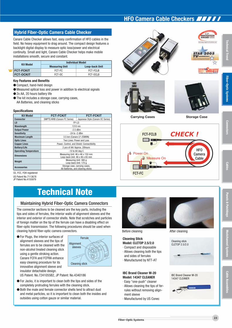
Hybrid Fiber-Optic Camera Cable CheckerCanare Cable Checker allows fast, easy confirmation of HFO cables in thefield. No heavy equipment to drag around. The compact design features abacklight digital display to measure optic loss/power and electrical continuity. Small and light, Canare Cable Checker helps make mobile installations smooth, secure and constant.
Kit ModelIndividual Model
Measuring Unit Loop-back UnitFCT-FCKIT FCT-FC FCT-FCLBFCT-OCKIT FCT-OC FCT-OCLB
Key Features and Benefits● Compact, hand-held design● Measured optical loss and power in addition to electrical signals● 2x AA, 20 hours battery life● The kit includes a storage case, carrying cases, AA Batteries, and cleaning sticks
SpecificationsKit Model FCT-FCKIT FCT-FCKIT
Connector SMPTE/ARIB (Canare FC Series) Japanese Style (Canare OC Series)LD FP-LDWavelength 1310 nmOutput Power -2.5 dBmSensitivity -24 to -2 dBmMaximum Length 3.5 km (Canare LF-2SM9N)Optic Lines Two Lines: Power and LossCopper Lines Power, Control, and Shield: ConnectibilityBattery/Life 2 pcs of AA/ Approx. 20hoursOperating Temperature -10 to 60 deg C
Dimensions Measuring Unit: 46 x 46 x 150 mmLoop-back Unit: 46 x 46 x 65 mm
Weight Measuring Unit: 380 gLoop-back Unit: 170 g
Accessories Storage case, carrying cases,AA Batteries, and cleaning sticks
CE, FCC, FDA registeredUS Patent No.7113678JP Patent No.4155979
Carrying Cases Storage Case
Maintaining Hybrid Fiber-Optic Camera ConnectorsThe connector sections to be cleaned are the key parts, including the tips and sides of ferrules, the interior walls of alignment sleeves and the interior and exterior of connector shells. Note that scratches and particles of foreign matter on the tip of the ferrule can have a disabling effect on fiber-optic transmission. The following procedures should be used when cleaning hybrid fiber-optic camera connectors.
● For Plugs, the interior surfaces of alignment sleeves and the tips of ferrules are to be cleaned with the non-alcohol treated cleaning stick using a gentle stroking action. Canare FCFA and FCFRA enhance easy cleaning procedure for its innovative alignment sleeve and insulator detachable design.
US Patent: No.7241055B2, JP Patent: No.4340186
● For Jacks, it is important to clean both the tips and sides of the completely protruding ferrules with the cleaning stick.
● Both the male and female connector shells tend to attract dust and metal particles, so it is important to clean both the insides and outsides using cotton gauze or similar material.
Before cleaning After cleaning
Ferrule
Alignmentsleeves
Cleaning stick
Cleaning StickModel: CLETOP 2.5/2.0· Compact and disposable· Allows cleaning both the tips and sides of ferrules
· Manufactured by NTT-AT
IBC Brand Cleaner M-20Model: 14347 CLEANER· Easy “one-push” cleaner· Allows cleaning the tips of fer-rules without removing align-ment sleeve
· Manufactured by US Conec
Cleaning stickCLETOP 2.5/2.0
IBC Brand Cleaner M-2014347 CLEANER
HFO Camera Cable Checkers
Fiber-Optic Systems
24Fiber-Optic Systems
Hybrid Fiber-optic Camera Connector Panels
Pre-terminated HFO camera connector panel with built-in splice enclosure box provides easy and quick installationbetween HD camera system and terminal panel or rack. By combining the unit and frame, HFO camera connector panelenables a variety of layouts depending on the system design.
■ COPS Series (SMPTE)Model Panel Size HFO Connectors* (Assembly)
COPS-FF3A Wall Mount Type3RU Height, W:197.6mm
2x FCFRA (FCS003A-FR)COPS-FM3A 2x FCMRA (FCS003A-MR)COPS-FF2A Wall Mount Type
2RU Height, W:197.6mm2x FCFRA (FCS003A-FR)
COPS-FM2A 2x FCMRA (FCS003A-MR)COPS3-FF3A Rack Mount Type
3RU6x FCFRA (FCS003A-FR)
COPS3-FM3A 6x FCMRA (FCS003A-MR)COPS3-FF2A Rack Mount Type
2RU6x FCFRA (FCS003A-FR)
COPS3-FM2A 6x FCMRA (FCS003A-MR)
* Each HFO connector is pre-terminated. (length: 0.3m)* Canare OC seires (Tajimi compatible type) is also available. Please contact us for more details.
Key Features and Benefits● Exclusive “5-directional Wiring”● Convenient to build I/O interface between HD facilities and HD OB vans● Variety of choice of 2RU/3RU and wall/rack mount● Pre-terminated HFO connectors reduce installation time dramatically.● Cost effective● Lightweight aluminum chassis
Vertical/Transverse placementTransverse placementVertical placement
5 directions of cablingas indicated by colored arrows
Enclosure UnitVertical Placement
Enclosure UnitTransverse Placement
5-directional WiringJP Patent No.4388540
■ Wiring Diagram
4- 7x10
143180197.6
57.2
132.
6
104
COPS-FF3A
7076.1
88.1
143
197.6180
4- 7x10
COPS-FF2A
4- 7x10
4.6
(121
.8)
482.6465428
132.
6
57.2
104
431.2
COPS3-FM3A
Accessories:Fiber-optic cable w/SC connector (2m), grounding cable, nylon connector,pin contact, socket contact, tie-band, fusion splice protection sleeve, splice holder, color-coded tube, mounting screw, laser warning label.Note: Assembly tools for the nylon connectors are NOT include. (AMP 91529-1: 26 to 22 AWG and AMP 91536-1: 20x2 to 16 AWG)
FCFRA Fiber-optic (SM) yellow1Fiber-optic (SM) yellow2
Power line (18AWG) blackPower line (18AWG) white
Nylon connectorControl (22AWG) grayControl (22AWG) red65
526
4 314
12
3
56546
2
SC
: Pin contact : Socket contact
SC
2
14 313
Ground (18AWG) green
HFO Camera Connector Panels
25Fiber-Optic Systems
Technical TrendFiber-O
ptic Systems
ConnectorsCables
Panels & Patchbays
Mutichannel System
sCable A
ssemblies
8014
0
210
(270
)
160
φ5
ABCD
Control (25AWG)Control (25AWG)
Ground (18AWG)
: Fusion splice connection
LF-2SM9
52
6
4Power line (20AWG)Power line (20AWG)Power line (20AWG)Power line (20AWG)
Fiber Optic (SM) BLUFiber Optic (SM) YEL
1
YEL
3
Nylon connectorGRYREDBLKBLKWHTWHTGRN
YEL
: Pin contact : Socket contact
SCSC
36 5 4
12
Model Panel Height DescriptionCOUS-FF3A 3RU Connector Unit w/ 2x FCFRA (FCS003A-FR)COUS-FM3A 3RU Connector Unit w/ 2x FCMRA (FCS003A-MR)COUS-FF2A 2RU Connector Unit w/ 2x FCFRA (FCS003A-FR)COUS-FM2A 2RU Connector Unit w/ 2x FCMRA (FCS003A-MR)COU-BP3A 3RU Blank PanelCOU-BP2A 2RU Blank PanelCOF-13A 3RU Frame for 1 UnitCOF-12A 2RU Frame for 1 UnitCOF-33A 3RU Frame for 3 UnitCOF-32A 2RU Frame for 3 Unit
* Each HFO connector is pre-terminated. (length: 0.3m)* Canare OC seires (Tajimi compatible type) is also available. Please contact us for more details.
Frame COF-**A
Connector Panel COPS*-***A
Blank PanelCOU-BP*A
Connector UnitCOUS-***A
Configuration Example
FCFA
FCC**N FCC**N
COPS-FF3A
COPS-FM3A
FCFAFCMA
FCMA
<Example of Use>
Hybrid Fiber-optic Splice Enclosures
The fiber-optic splice enclosure was designed specifically for use with hybrid fiber-optic camera cables. The enclosure is used to protect fusion splice connection parts after installation.
Model No. of cables Fusion splicetray No.
AdapterSC Nylon connector
FCE-2 2 1 4 2FCE-4 4 2 8 4FCE-6 6 3 12 6
● The enclosure is designed specifically for the hybrid fiber-optic camera cable (LF-2SM9), making installation and operation very easy.
● The enclosure can be installed on walls or placed flat. Mounting bracket (connector protection cover) can be detached from the box when installing in limited space.
● The enclosure is designed with two configurations, the top-bottom split design (FCE-2, FCE-4) and the removable panel design (FCE-6). Both designs enable easy installation of cables.
● The connection with hybrid fiber-optic receptacle cable is done by use of connectors, thus enabling easy interchanging of lines after installation.
● The tension member is insulated from the chassis.Note :The following tools are required for installing the nylon connector.AMP 91529-1 (26 to 22 AWG) and AMP 91536-1 (20x2 to 16 AWG)
■ Wiring Diagram
Type FCE-2 FCE-4FCE-6
A 170 240B 160 230C 150 220D 126 196
(mm)
(59.
2)(4
9.2)
(49.
2)
Cable insert hole Nylon connector
SC adapter
FCE-2
FCE-4
FCE-6
■ Individual Units and Parts
Accessories: Fiber-optic cable w/SC connector (2m), splice holder, fusion splice protection sleeve, nylon connector, pin contact, socket contact, tie band, grounding cable, color-coded tube.
FCE-2
HFO Camera Connector Panels, Splice Enclosures
Fiber-Optic Systems
26Fiber-Optic Systems
6-channel Fiber-optic Snakes
6-channel Fiber-optic Fantails
Type Model Length (m)
OM6PA OM6JA
LF-6SM9R
L
Heat Shrink Tubes Heat Shrink Tubes
Jacket color : black
OM6C10 10
OM6C20 20
OM6C25 25
OM6C35 35
OM6C50 50
OM6C100 100
OM6C150 150
OM6C200 200
● Ruggedized multichannel fiber-optic assemblies with robust 6-fiber
connector ● Single-mode, ITU-T G.657.A2 low bending loss and low water-peak
fiber ● Abrasion-resistance cable jacket ● Tensile strength: 700 N or less● Return loss: 45 dB or greater ( = 1.3 μm)● Insertion loss: 0.5 dB or greater ( = 1.3 μm)● 7-color connector rings included.● Blue dust cap makes it easier to distinguish OM6 from HFO camera connectors.
* Canare OM6 connectors are NOT compatible with other multichannel/hybrid fiber-optic connectors.
* IBC brand “one-push” cleaner M-20 is highly recommended for cleaning OM6 connectors. (see page 23, model: 14347 CLEANER)
Type Model Length (m)
OM6PRA
0.3m
SC×6
6
5
4
1
2
3
Jacket color : yellow IU-FCM-SET included
OM6S003-PR 0.3
OM6PRA
1.5m
SF Tube
SC×61
2
3
4
5
6
Jacket color : yellow IU-FCM-SET included
OM6S015-PR 1.5
OM6JRA
0.3m
SC×6
6
5
4
1
2
3
Jacket color : yellow IU-FCM-SET included
OM6S003-JR 0.3
OM6JRA
1.5m
SC×61
2
3
4
5
6
SF Tube
Jacket color : yellow IU-FCM-SET included
OM6S015-JR 1.5
● OM6 receptacle with 6 SC single-mode fiber cord (2.0mm).● Return loss: 45 dB or greater ( = 1.3 μm)● Insertion loss: 0.5 dB or greater ( = 1.3 μm)● Blue dust cap makes it easier to distinguish OM6 from HFO camera connectors.
* Canare OM6 connectors are NOT compatible with other multichannel/hybrid fiber-optic connectors. * IBC brand “one-push” cleaner M-20 is highly recommended for cleaning OM6 connectors. (see page 23, model: 14347 CLEANER)
OM6PA
OM6PRA
OM6JRA
OM6JA
Color Rings
∅ 40
4-M3 or ∅ 3.2
34
34
■ Hole Dimensions(with IU-FCM-SET)
Fiber-optic Cables
27Fiber-Optic Systems
Technical TrendFiber-O
ptic Systems
ConnectorsCables
Panels & Patchbays
Mutichannel System
sCable A
ssemblies
Type Model Length (m)
500mm500mm
LF-SM2T-4C
SC Plug SC Plug
Jacket color : black
4FS50T-SS 50
4FS100T-SS 100
4FS150T-SS 150
4FS200T-SS 200
500mm500mm
LF-SM2T-4C
LC Plug LC Plug
Jacket color : black
4FS50T-LS 50
4FS100T-LS 100
4FS150T-LS 150
4FS200T-LS 200
500mm500mm
LF-SM2T-4C
ST Plug ST Plug
Jacket color : black
4FS50T-ST 50
4FS100T-ST 100
4FS150T-ST 150
4FS200T-ST 200
■ Cable Assemblies
Tactical Fiber-optic Cable
Type Model No. ofch.
SalesUnits(m)
Nom.O.D.
(mm)
Weightkg/100m
TensionTolerance
(N)
StrengthMember
Min. Bend
Radius
Temp.Range(deg C)
Fiber-optic Unit
Fiber Attenuation Unit O.D.
Jacket color : black
LF-SM2T-4C 4100200500
7.8 4.9 1400 Aramidyarn
Equal toNom. O.D.
-55 to
+85SM 9/125
(low-water-peak)1.6 dB/km@1310 nm
2.0 mmincluding
aramid yarn
Jacket: TPU
LF-SM2T-4C● Heavy-duty and high flexibility * Crush resistance: 2,000 N/cm * Impact resistance: 300 impacts * Cycle flexing: 20,000 cycles● Single-mode● Color-coded breakout type unit● Thermoplastic polyurethane jacket● Aramid yarn strength member● 4-channel cable best suited for Quad-link 3G-SDI signals.
Particularly rugged multichannel fiber-optic cable designed for mobile applications.
Cross Section
LF-SM2T-4C
Key: F : Fiber + Aramid Yarn
# : Aramid Yarn
###
##FF
F
F
Single-mode Fiber-optic Cables (Multichannel)
Type Model No. of Ch.
SalesUnits(m)
Nom.O.D.
(mm)
Weightkg/100m
OuterJacket
TensionTolerance
(N)
Min.Bend
Radius
Temp.Range(deg C)
Fiber-optic Unit
Fiber Attenuation Unit O.D.
LF-SM2-6C
Jacket color: yellow
LF-SM2-2C 2
Call
7.4 5.4
PVC
290
10 xNom. O.D.
-40 to +75SM 9/125
+ Aramid yarn+ PVC jacket
0.5 dB/km@1310nm
2.0 mmincluding
aramid yarn
LF-SM2-4C 4 7.4 5.5 290
LF-SM2-6C 6 9.0 7.3 300
LF-SM2-8C 8 10.0 10.4 780
LF-SM2-12C 12 12.8 14.2 780
LF-SM2-16C 16 14.7 16.3 780
LF-SM2-24C 24 15.0 18.3 780
● Smooth PVC Jacket● Including a central strength member and a rip cord.
Fiber-optic Cables
Fiber-Optic Systems
28Fiber-Optic Systems
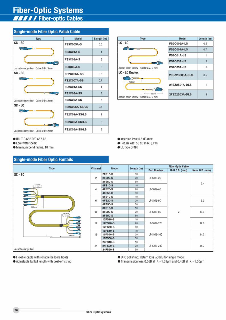
Single-mode Fiber Optic Fantails
Type Channel Model Length (m)Fiber Optic Cable
Part Number Unit O.D. (mm) Nom. O.D. (mm)
SC - SC
L 500mm
500mm
150mmPeel-off String
150mmPeel-off String
Jacket color: yellow
22FS10-S 10
LF-SM2-2C
2
7.4
2FS20-S 202FS50-S 50
44FS10-S 10
LF-SM2-4C4FS20-S 204FS50-S 50
66FS10-S 10
LF-SM2-6C 9.06FS20-S 206FS50-S 50
88FS10-S 10
LF-SM2-8C 10.08FS20-S 208FS50-S 50
1212FS10-S 10
LF-SM2-12C 12.812FS20-S 2012FS50-S 50
1616FS10-S 10
LF-SM2-16C 14.716FS20-S 2016FS50-S 50
2424FS10-S 10
LF-SM2-24C 15.324FS20-S 2024FS50-S 50
Type Model Length (m)
SC - SC
Jacket color: yellow Cable O.D.: 3 mm
FS3C005A-S 0.5
FS3C01A-S 1
FS3C03A-S 3
FS3C05A-S 5
SC - SC
Jacket color: yellow Cable O.D.: 2 mm
FS2C005A-SS 0.5
FS2C007A-SS 0.7
FS2C01A-SS 1
FS2C03A-SS 3
FS2C05A-SS 5
SC - LC
Jacket color: yellow Cable O.D.: 2 mm
FS2C005A-SS/LS 0.5
FS2C01A-SS/LS 1
FS2C03A-SS/LS 3
FS2C05A-SS/LS 5
Type Model Length (m)
LC - LC
Jacket color: yellow Cable O.D.: 2 mm
FS2C005A-LS 0.5
FS2C007A-LS 0.7
FS2C01A-LS 1
FS2C03A-LS 3
FS2C05A-LS 5
LC - LC Duplex
Jacket color: yellow Cable O.D.: 2 mm
2FSZ2S005A-DLS 0.5
2FSZ2S01A-DLS 1
2FSZ2S03A-DLS 3
Single-mode Fiber Optic Patch Cable
● Flexible cable with reliable bellcore boots● Adjustable fantail length with peel-off string
● UPC polishing; Return loss 50dB for single mode● Transmission loss 0.5dB at =1.31μm and 0.4dB at =1.55μm
● ITU-T G.652.D/G.657.A2● Low-water-peak● Minimum bend radius: 10 mm
● Insertion loss: 0.5 dB max.● Return loss: 50 dB max. (UPC)● UL type OFNR
150 mm
150 mm
Fiber-optic Cables
150 mm
150 mm
29Fiber-Optic Systems
Technical TrendFiber-O
ptic Systems
ConnectorsCables
Panels & Patchbays
Mutichannel System
sCable A
ssemblies
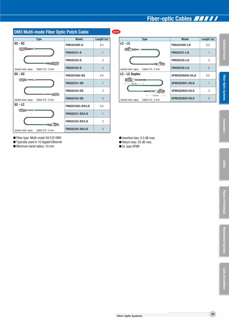
Type Model Length (m)
SC - SC
Jacket color: aqua Cable O.D.: 3 mm
FM33C005-S 0.5
FM33C01-S 1
FM33C03-S 3
FM33C05-S 5
SC - SC
Jacket color: aqua Cable O.D.: 2 mm
FM32C005-SS 0.5
FM32C01-SS 1
FM32C03-SS 3
FM32C05-SS 5
SC - LC
Jacket color: aqua Cable O.D.: 2 mm
FM32C005-SS/LS 0.5
FM32C01-SS/LS 1
FM32C03-SS/LS 3
FM32C05-SS/LS 5
Type Model Length (m)
LC - LC
Jacket color: aqua Cable O.D.: 2 mm
FM32C005-LS 0.5
FM32C01-LS 1
FM32C03-LS 3
FM32C05-LS 5
LC - LC Duplex
Jacket color: aqua Cable O.D.: 2 mm
2FM3Z2S005-DLS 0.5
2FM3Z2S01-DLS 1
2FM3Z2S03-DLS 3
2FM3Z2S05-DLS 5
OM3 Multi-mode Fiber Optic Patch Cable
● Fiber type: Multi-mode 50/125 OM3 ● Typically used in 10 Gigabit Ethernet● Minimum bend radius: 10 mm
● Insertion loss: 0.3 dB max.● Return loss: 25 dB max.● UL type OFNR
Fiber-optic Cables