
FIBER OPTIC RS-OCT PROBE John Acevedo Kelly Thomas Chris Miller Advisors: Dr. Patil Dr....
21
FIBER OPTIC RS-OCT PROBE John Acevedo Kelly Thomas Chris Miller Advisors: Dr. Patil Dr. Mahadevan-
-
Upload
grant-harrington -
Category
Documents
-
view
216 -
download
0
Transcript of FIBER OPTIC RS-OCT PROBE John Acevedo Kelly Thomas Chris Miller Advisors: Dr. Patil Dr....
FIBER OPTIC RS-OCT PROBE
John Acevedo Kelly Thomas Chris MillerAdvisors: Dr. PatilDr. Mahadevan-Jansen

Epithelial cancer types
Epithelium – cells that line hollow organs and make up the outer surface of the body (skin)
Basal Cell Carcinoma: 1 million new cases are diagnosed each year in the U.S. The basal cells line the deepest layer of the epidermis
Squamous Cell Carcinoma: More than 700,000 new cases are diagnosed every year. Chronic exposure to sunlight is the cause of most
squamous cell carcinoma and basal cell carcinoma. Optical imaging such as Optical Coherence
Tomography (OCT) can noninvasively serve as a diagnostic and monitoring tool of epithelial cancers, and can evaluate therapeutic responses

RS and OCT are complimentary
Raman Spectroscopy Strengths
Biochemical Specificity
Limitations No spatial Information Susceptible to
sampling error
Optical Coherence Tomography Strengths
Micron-scale structural resolution
Real-time imaging speeds
Limitations Insensitive to tissue
biochemical composition

Dr. Patil’s RS-OCT probe
RSOD1310 nm C
BD
BPF
AI/AODAQ
50/50
785 nmEC
LS
Spectrograph
CCD
Drive Waveform
FS
Sample
ProbeGC
Raman Subsystem
OCT Subsystem
RSOD1310 nm C
BD
BPF
AI/AODAQ
50/50
785 nmEC
LS
Spectrograph
CCD
Drive Waveform
FS
Sample
ProbeGC
Raman Subsystem
OCT Subsystem

Procedure
1. Turn on OCT component 2. Acquire tomographical map3. Detect area of interest4. Turn off OCT component5. Turn on RS component6. Acquire biochemical composition of
area of interest7. Turn off RS component

Reason for fiber optic RS-OCT probe
Improve detection and diagnosis of cancer Hand held device will facilitate the use RS-
OCT probe A fiber optic probe will decrease the size of
the current probe Potential endoscopic use, non-invasive Cost effective

Problem Statement
5”
8”
Miniaturizing sample arm of current RS-OCT probe

Design Criteria
Meet existing RS-OCT probe performance and functionality Decrease size of probe to < 1 cm in
diameter Reach a scan rate of RS and OCT to 4
frames per second Reach a scan range of at least 3 mm depth OCT sensitivity of -95 dB RS collection efficiency of 10 seconds Spot size for OCT should be < 50 microns
Determined by depth of focus
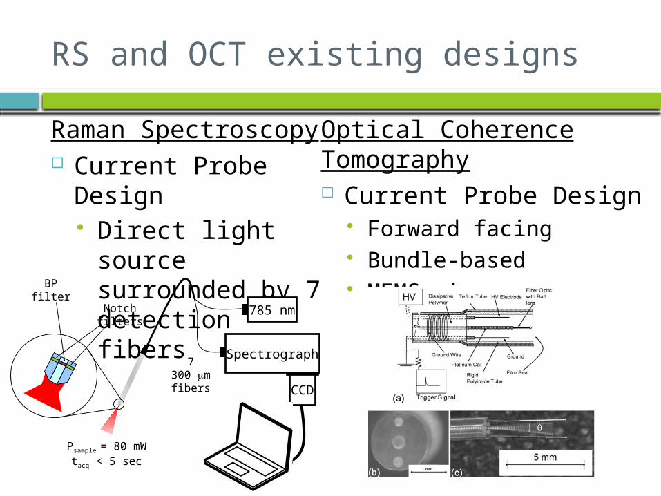
RS and OCT existing designs
Raman Spectroscopy Current Probe
Design Direct light source
surrounded by 7 detection fibers
Optical Coherence Tomography Current Probe Design
Forward facing Bundle-based MEMS mirror
Spectrograph
CCD
785 nm
7300 mm
fibers
BPfilter
Notchfilters
Psample = 80 mWtacq < 5 sec

Challenges
Quality compensation from combining RS and OCT RS requires narrow band of light source and
multi-mode fibers for optimum specificity OCT requires broad band of light source and
single-mode fibers for optimum specificity Develop scanning technique for the OCT probe
in such a small area Spatial registration of RS and OCT data sets Obtaining material for tests

Current Design
Forward facing Electrostatic scanning probe for OCT
component Located in the center
Fiber-optic array for RS component
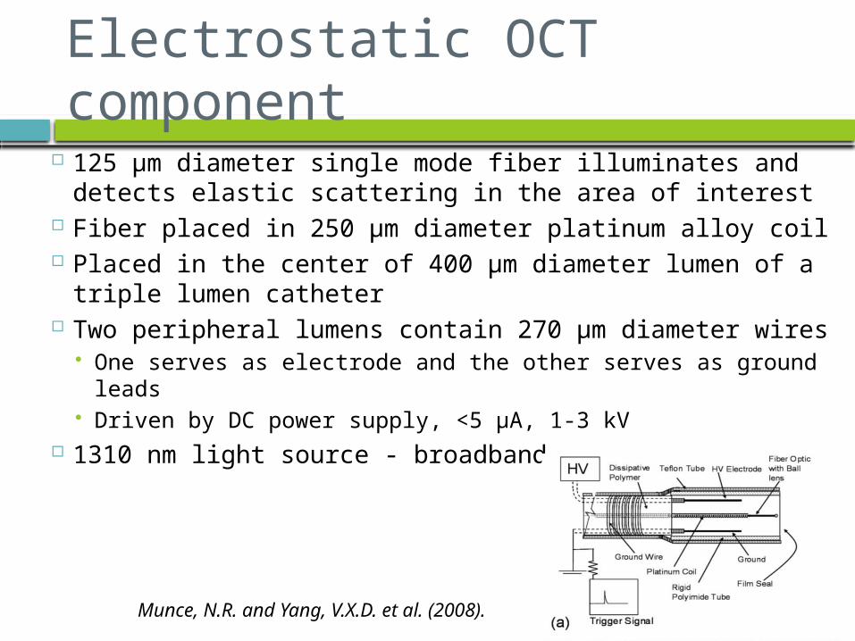
Electrostatic OCT component
125 µm diameter single mode fiber illuminates and detects elastic scattering in the area of interest
Fiber placed in 250 µm diameter platinum alloy coil Placed in the center of 400 µm diameter lumen of a
triple lumen catheter Two peripheral lumens contain 270 µm diameter wires
One serves as electrode and the other serves as ground leads
Driven by DC power supply, <5 µA, 1-3 kV 1310 nm light source - broadband
Munce, N.R. and Yang, V.X.D. et al. (2008).

Electrostatic OCT component Electrostatic driven cantilever to create a compact, wide
angle, rapid scanning forward viewing probe1. Cantilever is neutral and is attracted to electrode2. Cantilever touches electrode and acquires the same
potential3. Charge dissipates through the polymer from the cantilever
and repels from electrode4. Cantilever touches ground and becomes neutral again5. Process restarts enacting a scanning motion

Fiber Optic Array RS Component
Multi-mode fibers (200 µm)set on either side of the OCT scanning fiber
One narrow band (785 nm) light sources on one side
Light source Collection
Highest concentration of collection
OCT

Future work
Build prototype Test prototype Evaluate effectiveness Improve design by adding more
collection fibers Creating SolidWorks 3D design Prepare poster presentation
Current Progress
Voltage source and optical fibers have been obtained
Platinum coil or suitable replacement is needed
Find a suitable replacement for dissipative polymer if polymer cannot be obtained Capacitor, resistor, inductor

References
Patil, C.A. (2009). Development combined raman spectroscopy-optical coherence tomograpgy for the detection of skin cancer. Disertation submitted to faculty of Graduate school of Vanderbilt University.
Munce, N.R. and Yang, V.X.D. et al.(2008). Electrostatic forward-viewing scanning probe for doppler optical coherence tomography using a dissipative polymer catheter. Optical letters, 33, 7, 657-60.

Questions?
Specific Aims
1. Combine RS-OCT techniques into a fiber optic device to replace sample arm of current probe
2. Maximize Raman detection time efficiency
3. Integrate multi-mode and single-mode fibers into probe without compromising RS-OCT functionality

Raman Spectroscopy
Inelastic scattering (Stokes and Anti-Stokes) Occurs 1 in 10 million
compared to elastic Frequency of light scattered
from a molecule dependent on structural characteristics of molecular bonds
Able to determine malignant from non-malignant tissue
Gives no spatial information All sorts of epithelial
diseasesRaman Shift (cm-1) = f ( ) – f ( )
n1n0
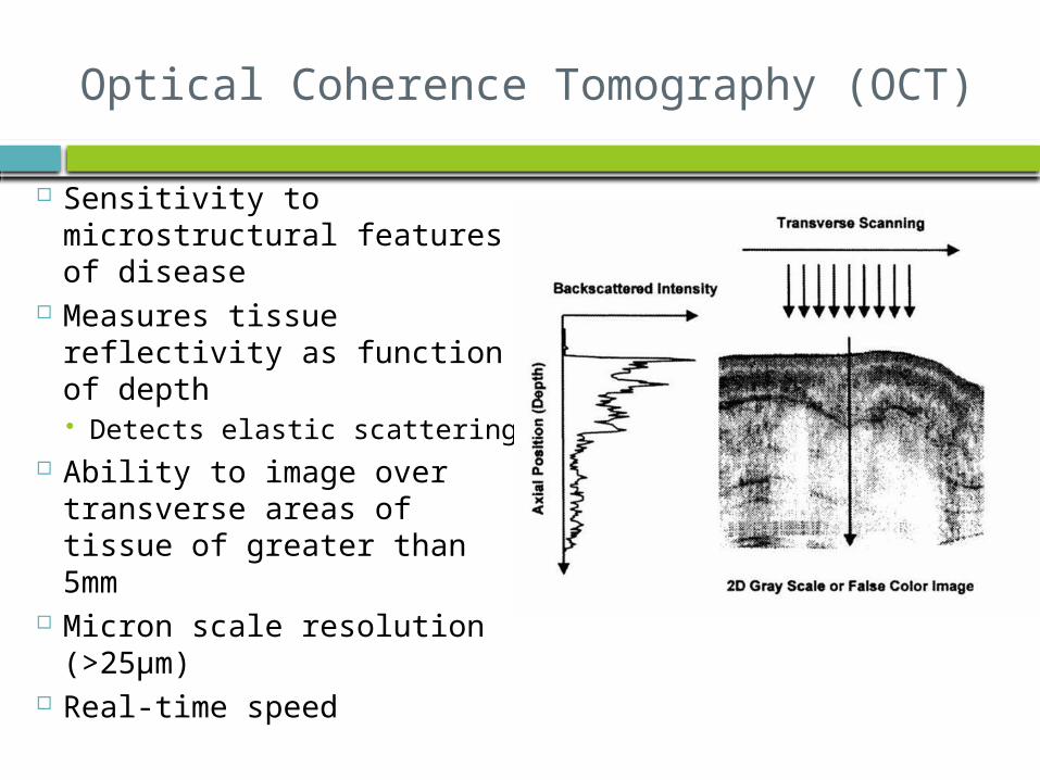
Optical Coherence Tomography (OCT)
Sensitivity to microstructural features of disease
Measures tissue reflectivity as function of depth Detects elastic scattering
Ability to image over transverse areas of tissue of greater than 5mm
Micron scale resolution (>25µm)
Real-time speed


