Fiber Optic Magnetic Field Sensors
86
KUNGL TEKNISKA HÖGSKOLAN Institutionen för Signaler, Sensorer & System 10044 STOCKHOLM ROY AL INS TITUTE OF TECHNOLOGY Instrumentation Laboratory Elektrisk mätteknik F ib r e O ptic Magne tic F ie ld S en sors Util iz in g Iron Gar ne t Mat erials b y Hans Sohls tr öm TRITA-ILA 93.01 S-10044 STOCKHOLM Department of Signals, Sensors & Systems
-
Upload
sakhorn-rimjaem -
Category
Documents
-
view
243 -
download
0
Transcript of Fiber Optic Magnetic Field Sensors
8/3/2019 Fiber Optic Magnetic Field Sensors
http://slidepdf.com/reader/full/fiber-optic-magnetic-field-sensors 1/86
KUNGL TEKNISKA HÖGSKOLANInstitutionen förSignaler, Sensorer & System
10044 STOCKHOLM
ROYAL INSTITUTEOF TECHNOLOGY
Instrumentation Laboratory Elektrisk mätteknik
Fibre Optic Magnetic Field SensorsUtilizing Iron Garnet Materials
by
Hans Sohlström
TRITA-ILA 93.01
S-10044 STOCKHOLM
Department ofSignals, Sensors & Systems

8/3/2019 Fiber Optic Magnetic Field Sensors
http://slidepdf.com/reader/full/fiber-optic-magnetic-field-sensors 2/86

8/3/2019 Fiber Optic Magnetic Field Sensors
http://slidepdf.com/reader/full/fiber-optic-magnetic-field-sensors 3/86

8/3/2019 Fiber Optic Magnetic Field Sensors
http://slidepdf.com/reader/full/fiber-optic-magnetic-field-sensors 4/86

8/3/2019 Fiber Optic Magnetic Field Sensors
http://slidepdf.com/reader/full/fiber-optic-magnetic-field-sensors 5/86
V
Descriptors
YIG, iron garnets, rare earth garnets, magneto-optics, optical waveguide,
fibre optic sensors, ma gnetic field measu rem ent , cur ren t m easu rem ent .
Abstract
This thesis deals with the subject of fibre optic magnetic field sensors
utilizing iron garnet materials . Such materials exhibit a large Faraday
rotation which make them advantageous for application in compact mag-
net ic field sensors.
After a n in tr oduction, in wh ich fibre optic sensors a nd optical meth ods t o
measure e lectr ic current are reviewed, the original research work is
summarized.
A system for th e measu remen t of the m agneto-optic properties of tr an s-
par ent ma terials is described. Measur ement results, showing th e influence
of temperature, magnetic field direction and sample treatment on thema gneto-optical propert ies of YIG-cryst als, ar e pr esent ed. The pr oper ties of
thin magneto-optical waveguiding films have also been studied using
different light coupling methods. Measurement results obtained for holo-
graphic grating, prism and edge (end-fire) light coupling to different
substitu ted YIG films a re pr esent ed. It is shown th at th e launching method
ma y affect t he propert ies to be measu red.
The design a nd perform an ce of several versions of extrin sic guided wa ve
fibre optic magnetic field sensors are then reported. The sensors employ
substituted YIG (Yttrium Iron Garnet, Y3Fe5O12) thin film waveguides as
sensing elements. Polarization maintaining fibres were used as feed andreturn to provide two signal channels. The signals were combined in a
balanced measu remen t system, providing insensitivity to both fluctu at ions
in optical power a nd loss. Sensors ha ve been ma de both with sepa ra te fibres
to guide the light to and from t he sensin g element an d with a single fibre for
both functions. The two fibre version, although less ”elegant”, is found to
ha ve a better perform an ce. This version a lso ma kes it possible to deter mine
both the magnitude and sign of the magnetic field. Measurement results
indicate a usable measurement range of at least several mT with a noise
equivalent magnetic field level of less than 8nT/ √ Hz.
The design and performance of multimode fibre optic magnetic fieldsensors ut i l iz ing the Faraday effect in an epitaxia l ly grown thick
(YbTbBi)IG film is also described. This type of sensor is found to be linear
over a ra nge from 27mT t o less th an 270nT. Sensor pr ototypes suit able for
current monitoring in high voltage transmission lines have also been
developed.

8/3/2019 Fiber Optic Magnetic Field Sensors
http://slidepdf.com/reader/full/fiber-optic-magnetic-field-sensors 6/86
VI

8/3/2019 Fiber Optic Magnetic Field Sensors
http://slidepdf.com/reader/full/fiber-optic-magnetic-field-sensors 7/86
VII
List of publications
This t hesis is based on th e work cont ained in th e following papers:
A: U. Holm, H. Sohls tröm and T. Brogårdh, ”Measurement sys tem for
magneto-optic sensor materials”, J . Phys. E: Sci . Instrum., vol. 17,
p. 885–889, 1984.
B: U. Holm, H. Sohlstr öm a nd T. Brogår dh, ”YIG-sensor design for fibre
optical magnetic field measurement”, OFS 84 , R. Th. Kersten and
R. Kist, p. 333–336, VDE-Verla g, Berlin, 1984.
C: U. Holm and H. Sohls t röm, Measurement of YIG crystal characteristics
for the design of optical magnetic field sensors , TR84.01, Instrumenta-
tion La borat ory; Royal In st itu te of Techn ology, Stockh olm, 1984.
D: H. Sohlstr öm, U. Holm an d K. Svantesson, ”A Polar izat ion Based Fibre
Optical Sensor System Using a YIG Optical Waveguide for Magnetic
Field Sensing”, S prin ger proceed in gs in Ph ysics 44: Opt ical Fiber
Sensors , H. J. Arditty, J. P. Dakin, and R. Th. Kersten, p. 273–278,
Springer-Verlag, Berlin, 1989.
E: H. Sohls tröm, U. Holm an d K. G. Svant esson, ”Chara cterization of
Magnetooptical Thin Films for Sensor Use”, S PIE Proc Electro-Optic
and Magneto-Optic Materials and Applications, J . P. Cast era , vol. 1126,
p. 77–84, 1989.
F: K. Svant esson, H. Sohlstr öm an d U. Holm, ”Magneto-optical garnet
ma ter ials in fibre optic sensor systems for ma gnetic field sen sing”, SPIE
Proc Electro-Optic and Magneto-Optic Materials and Applications II ,
H. Damm an n, vol. 1274, p.260–269, 1990.
G: H. Sohls tr öm a nd K. Svant esson, ”A waveguide based fibre optic
magnetic field sensor with directional sensitivity”, SPIE Proc Fiber
Optic S ensors: En gineering an d A pplications , A. J . Bruinsma and
B. Culshaw, vol. 1511, p. 142–148, 1991.
H: H. Sohlstr öm a nd K. Svan tesson, ”The perform an ce of a fibre optic
magnetic field sensor utilizing a magneto-optical garnet”, Fiber and
Integrated Optics, vol. 11, p.137–141, 1992, also pres ent ed at th e OFS8
conference in Mont erey, J an . 92.

8/3/2019 Fiber Optic Magnetic Field Sensors
http://slidepdf.com/reader/full/fiber-optic-magnetic-field-sensors 8/86
VIII

8/3/2019 Fiber Optic Magnetic Field Sensors
http://slidepdf.com/reader/full/fiber-optic-magnetic-field-sensors 9/86
IX
Contents
Abst ract .............................................................................................................V
List of pu blicat ions ......................................................................................... VII
Cont en ts ........................................................................................................... IX
1. The a im a nd organizat ion of the t hesis ........................................................ 1
2. Int roduction ................................................................................................... 3
Fibr e opt ic sen sors .................................................................................. 3
Magnet ic field measu rement .................................................................. 7
Measu rement of elect r ic cur ren t ............................................................ 9
Opt ical methods for magn et ic field a nd ................................................. 9
YIG ........................................................................................................ 183. Sta r tin g point s for th e sensor development work ..................................... 22
4. Mat eria l cha ra cteriza tion mea su rem ent s .................................................. 24
Bu lk mater ia ls ...................................................................................... 24
Wavegu ides ........................................................................................... 30
5. Sen sors. ........................................................................................................ 35
Sin gle-mode systems ............................................................................. 35
Mu lt imode systems ............................................................................... 41
6. Conclusions .................................................................................................. 45
7. Ackn owledgem en ts ...................................................................................... 46
Refer ences ........................................................................................................ 47Comm ents on th e au thorsh ip of the paper s ................................................... 55
Paper abst racts ................................................................................................ 56
Paper repr in t s .................................................................................................. 59
Paper A
Paper B
Paper C
Paper D
Paper E
Paper F
Paper GPaper H

8/3/2019 Fiber Optic Magnetic Field Sensors
http://slidepdf.com/reader/full/fiber-optic-magnetic-field-sensors 10/86
X

8/3/2019 Fiber Optic Magnetic Field Sensors
http://slidepdf.com/reader/full/fiber-optic-magnetic-field-sensors 11/86
Fibre Optic Magn etic Field S ensors Utilizin g Iron Garn et Materials
1
1. The a im and organ iza t ion of the th esis
The industrial development has created a growing demand for new types of
measu remen t a nd t herefore n ew types of sensors, to enha nce the qua lity of
different processes. The physical environment for the sensors has, at the
sam e tim e, become t ougher an d more electr oma gnetically polluted.
To overcome the electromagnetic pollution and also to achieve other
advantages , there has , s tart ing in the mid seventies , been a s teadily
growing int erest in fibre optic sensors. Opt ical m eth ods h ave long been u sed
for mea sur ement pur poses, but th e t echn ological ba se developed for fibre
optic comm un icat ion applicat ions ha s widened th e scope considera bly. Fibre
optic remote sensing system s, providing imm un ity to electr oma gnetic int er -feren ce, electr ical isolat ion an d a nu mber of oth er a dvant ages, could n ow be
developed.
The mea sur ement of magnetic field or cur ren t in electr ical power system s
ar e applicat ions in wh ich t hese advan ta ges are very significan t.
This th esis is to a lar ge extent based on work ma de as par t of th e ”Single
Mode Sensor P roject” th at was st ar ted in 1981 as a co-opera tive effort by the
Instrumentation Laboratory of the Royal Institute of Technology, the
Inst itu te of Microelectronics (IM) and the Institute of Optical Research (IOF).
The project was financed by the National Swedish Board for Technical
Development (STU).The aim of the project was to study the applicability of single mode
optical fibre technology for sensor use. ASEA AB (now ABB), one of the
proponents of the project , had a t that t ime developed a number of
multimode fibre optic sensors. Partly because of their interest the develop-
ment of a magnetic field or electric current sensor was chosen as the
working goal.
Most of the electric current sensors developed at that time utilized the
Faraday effect in long lengths of fibre, coiled around the conductor. The
difficulties encountered with such sensors led us to study sensors based on
localized sensing elements made from materials having a large Faradayrotation, e.g. YIG (Y3Fe5O12).
During the early stages of the project work, polarization maintaining
fibres became available. We then recognized the possibility of a system in
which polarisation maintaining fibres were used to carry the light to and
from a sensing element in t he form of a YIG waveguide.
Stu dies of mult imode sensors u sing bulk YIG or th ick films of substitu ted
YIG , were also carried out. A number of such sensors were developed for
different applicat ions.
The a im of th is th esis is to stu dy th e feasibility of ma gnetic field sens ors
based on ir on gar net ma ter ials. As both single-mode and m ult imode sensors

8/3/2019 Fiber Optic Magnetic Field Sensors
http://slidepdf.com/reader/full/fiber-optic-magnetic-field-sensors 12/86
Hans Sohlström
2
Fig.1. A m agnetic field sensor in th e form of a waveguid ing ”chip” – the idea
as envisioned d urin g th e initial stages of the project.
are treated, the thesis can also be said to form a comparison of the two
types.
Measurement technology is an application oriented research area, and
the stress in this thesis is on the sensor development and the material
cha ra cterizat ion. The paper s on wh ich t he t hesis is based describe differen taspects of the sensor development work, from the initial ideas to working
sensor prototypes. In this summary I will primarily motivate and discuss
the work in order to give a context to the different papers. For this purpose
the summary includes an introduction in which the theory is outlined and
also some illustr at ive results , tha t were omitt ed in th e papers due t o the
limitations of the conference contribution format. The introduction also
contains an overview of fibre optic sensors and current measurement in
general. In section 3, I then outline the sensor development and the role of
th e ma ter ial cha ra cter ization. The sum ma ry of my work is given in sections
4 an d 5. At th e end of each of these t wo sections r eferen ces ar e given t o th edifferent papers. Finally, in the conclusion, I summarize and speculate
somewha t a bout th e implicat ions of th e results.

8/3/2019 Fiber Optic Magnetic Field Sensors
http://slidepdf.com/reader/full/fiber-optic-magnetic-field-sensors 13/86
Fibre Optic Magn etic Field S ensors Utilizin g Iron Garn et Materials
3
2. In t roduct ion
Fibre opt ic s ensors
Definit ions
A fibre optic sensor consists of an optical sensing element which under the
influen ce of th e quan tit y to be measu red m odula tes light, an d optical fibres
to guide th e light t o and from t he sensing element. When a lso th e sensing
elemen t cons ists of optical fibres, th e sensor is intrinsic, and when t he fibres
ar e only ut ilized to guide the light t o an d from t he sensin g element , which is
itself external to the fibre, the sensor is extrinsic. In literature, the term
fibre optic sensor is somet imes r eserved for th e int rinsic sensors only.
This definition does not include pyrometers that use an optical fibre
between t he collectin g optics an d t he det ector. Form ally it a lso excludes t he
pyrometr ic devices tha t m easur e the t empera tu re of a m etallic film on th e
fibre end and similar devices where the sensing element ”emits light”,
alt hough t hey a re often considered to be fibre optic sensors.
Another class of sensors th at should be men tioned in this cont ext ar e th e
optically powered electronic sensors or hybrid sensors. As all th eir conn ec-
tions with th e out side world ar e optical, they shar e ma ny of the advan ta ges
of the fibre optic sensors, while at th e sam e time t hey allow th e use of esta b-
lished electronic sensing principles. They may also provide a way for
convent iona l sensors to be integra ted int o optical sensor net work s.
His torical notes
Optical measurement methods have long been used: optical telephone
transmission was patented in 1880, and patents from 1927 (Marconi Co.)
and 1934 (American Telephone & Telegraph Co.)1 show the principles of
optical fibres, wavelength multiplexing, etc. Without usable optical fibresan d laser light sour ces, however, litt le progress wa s ma de. In t he 1960’s t he
laser was invented and optical fibres became available, figure2. The rapid
development in the optical communications field has since then made
opt ical and electr o-opt ical component s ava ilable at r easona ble prices also for
measur ement applicat ions.
In the first fibre optic sensors that were developed, bundles of optical
fibres were u sed2, but similar sen sors with single fibres soon a ppear ed 3.
Dur ing th e ear ly 70’s ma ny of th e comm only used sen sing prin ciples where
developed 4,5,6,7,8. Since then, the technological advances of the fibre optic
communications research and development have immediately been takenadvan ta ge of in th e sensor comm un ity.

8/3/2019 Fiber Optic Magnetic Field Sensors
http://slidepdf.com/reader/full/fiber-optic-magnetic-field-sensors 14/86
Hans Sohlström
4
Limit for thesilica fibre
1968 1970 1972 1974 1976 1978 1980 1982 1984
10 4
10 3
10 2
10 1
10 0
10 –1
10 –2
10 –3
Year
F i b r e l o s s [ d B / k m ]
Fig.2. Th e m inim um losses of fibres d eveloped for optical com m un ications.
The truly unique features of the fibre optic sensors, their immunity to
electromagnetic interference and their electrical isolation, were recognized
from t he very sta rt , and scenar ios from th e sevent ies indicat ed a complete
switch to optical measurement technologies. What was not, however,
th oroughly recognized was th at indust ry rea lly needed reliable sta nda rdized
equipment with proven performance, not laboratory prototypes. After a
general disa ppointm ent at th e end of th e 80’s, ther e is now in t he 90’s a
renewed optimism, th ough on a more realistic scale, as th e first indust rial
prototypes of fibre optic sensors are being introduced. One of the leading
applicat ion ar eas for th is is th e electr ical power indu str y, one of th e ar eas
where the original interest first s tirred, indicating the important role of
tim e an d a pioneerin g applicat ion in t he accepta nce of new t echn ologies.
Principles
J ust as with th e convent iona l electr ic sensors th e nu mber of combina tions of
measurement quantity, sensing principle and output parameter is large.
The output parameter, the type of modulation that carries the information
from th e sensin g elemen t is a possible pr inciple of class ificat ion.The optical power or th e intensity of the returned light is a fundamental
par am eter. In fact, int ensity is the only quan tity we can measu re. All oth er
quantities must in some way be converted to intensities at one or more
detectors a nd possibly with a varia tion with t ime.
The use of the term intensity here is somewhat unclear. Intensity or
radiant intensity is, according to international standards, defined as power
per solid angle. Although t his qua nt ity is modulat ed when t he t ota l power is
modulated, it would in principle be more correct to speak of optical power
and power modulation. The use of th e ter m intensity as a relative measure
of power is, however, established in literature and will also be followed inth is text.

8/3/2019 Fiber Optic Magnetic Field Sensors
http://slidepdf.com/reader/full/fiber-optic-magnetic-field-sensors 15/86
Fibre Optic Magn etic Field S ensors Utilizin g Iron Garn et Materials
5
In an extrinsic intensity sensor the modulation can take place in an
optical system with moving parts9, a piece of material with an environ-
mentally dependent optical loss10 , etc. In an intrinsic sensor the modula-
tion is caused by a variation in the optical properties of the fibre itself.
Several loss mechanisms can be exploited, microbending11 ,12 , reflections
from gratings in the fibre13 , temperature dependent scattering in thefibre14 , losses cau sed by dopan ts in t he fibre a nd light decoupling from th e
fibre15 ar e some examples.
Several of th ese are loss mechanisms t ha t a re a lways present in a fibre
optic system . This indicates a ma jor weak ness of an int ensity based sen sor:
th ere is in pr inciple always a loss varia tion in th e optical system a nd t his
could not directly be discrim inat ed from var iat ions in t he mea sur an d. Often
however, some known properties of the measurand signal can be used to
separ at e it from th e loss var iat ion.
To completely remove the uncertainty that is created by the loss varia-
tion, a system with a reference cha nn el can be used. In such a system twolight int ensities are m easur ed. If th e relation between t he influence of the
loss and the influence of the measurand is different for the two channels,
the influence of the loss can be removed. One realization of this is the
balanced system in which t he su m of th e two detected in ten sities is affected
by the sys tem loss and the dis tr ibution between them only by the
measu ra nd. A similar approach is to use the int ensity var iations with t ime
to achieve a system t ha t is independen t of th e absolut e inten sity. The use of
fluorescence decay for t empera tu re sensin g has been st udied16.
Th e wavelength of the light can be used to car ry inform at ion in severa l
ways. The sensing element can cause a wavelength dependent loss and
tr an smit only cert ain wa velengths of th ose emitt ed from a broadban d light
source17 . The sensing element can also receive light with one wavelength
and emit light with another. The information can then lie in the spectral
content of the emitted light18 , in which case it is a tr ue wavelength modu-
lation, or in t he int ensity of th e convert ed light , in which case it is better
described as an in ten sity based system , perh aps with a reference cha nn el.
The phase of the light is used in the very sensitive interferometric
sensors19. In such a sensor the free-path arms of a conventional inter-
ferometer a re r eplaced by optical fibres t ha t ma ke t he int erferometer m uch
more rugged and at the same time very sensitive to any change in the
effective refractive indices or lengths of the fibres. The changes can for
example be caused by an absolute rotation, making the device a rotation
sensor; th e environment al pr essure, mak ing it a very sensitive hydrophone
or a magnetostrictive perturbation, making it a very sensitive magneto-
meter.
Th e polarization state of the light can also be utilized in the sensing
element. The most usu al examples of this ar e sensors u sing the Fa ra day
effect, as will be further discussed below, but extrinsic electro-optic electric
field sensors20 an d pressu re sensors ba sed on ph otoelastic effects in extr in-
sic sensors21 or in fibres2 2 ,2 3 can a lso be found in l i tera ture . The

8/3/2019 Fiber Optic Magnetic Field Sensors
http://slidepdf.com/reader/full/fiber-optic-magnetic-field-sensors 16/86
Hans Sohlström
6
polarization state can, however, not be used as the information carrying
para meter in t he fibre.
Most of the sensors that use polarization modulation in the sensing
element internally convert it to an intensity modulation. Alternatively, it
could be converted to two different intensities creating a balanced system,
cf. above. The use of a polarization maintaining optical fibre makes itpossible to tr an smit th ese two cha nn els in one fibre core.
Single-mode or m ul t im ode
Out of the above ment ioned par am eters, only the wavelength an d th e inten -
sity can be maint ained when t he light propagates along a multimode fibre.
The optical loss variation always present in a practical system, however,
limits the applicability of intensity as the information carrier. The many
different propagation modes allowed in the multimode fibre, give rise to a
dispersion that destroys the phase information and causes a bandwidth
limitat ion for t he int ensity inform at ion.The core of a single-mode fibre is so thin, normally 5–10µm, that only
one mode is allowed. For monochromatic light it has no dispersion. The
sma ll dispersion a ssociated with th e spectr al width of th e light can, in ma ny
inst an ces, be ignored. The pha se inform at ion is ret ain ed in th e single-mode
fibre. The pha se drift a ssociat ed with cha nges of th e optical length of th e
fibre mu st, however, be taken into accoun t. The polar isat ion st at e can not be
maintained for any longer lengths of fibre because the almost perfect
circular symmet ry of th e fibre ma kes th e two ort hogona l polar ization m odes
degenerat e, allowing the polar ization sta te t o cha nge un der t he influence of
the fibre birefringence.
Th e polarization maintaining (p. preserving) fibre is a special type of
single-mode fibre with a core t ha t is elliptical or h as an an isotr opic index of
refraction. This removes the degeneracy of the fibre polarization modes,
allowing th em t o exist indepen dent ly of each oth er. Polar ized light coupled
into th e fibre will, th us, be distribut ed into th e two polarization modes a nd
will then travel along the fibre without mode coupling. The polarization
sta te is in fact not generally maintained as the phase relation between the
two ort hogona l component s present at th e input is lost du e to the differen ce
in propagation const an t for t he t wo modes. The intensity ra tio between th e
light in the two modes is however maintained. Only for the special case
wher e only one polar ization m ode is excited t he fibre is r eally polar ization
maintaining.
P lana r wa vegu ides
J ust as light can be guided in a n optical fibre which is a circular waveguide,
it can be guided in a planar waveguide. The simplest st ru ctu re is th e planar
slab guide, figure3, wher e a plana r film of refra ctive index n f is san dwiched
between a substrate and a cover material with lower refractive indices
(nf >n
s, n
c). Often the cover material is air (n
c=1). In the slab guide there is
no confinement of the light in t he pla ne of the film.

8/3/2019 Fiber Optic Magnetic Field Sensors
http://slidepdf.com/reader/full/fiber-optic-magnetic-field-sensors 17/86
Fibre Optic Magn etic Field S ensors Utilizin g Iron Garn et Materials
7
Substrate, n s
Cover, nc
Film, n f h
Fig.3. T he planar slab waveguid e.
The light is guided in the same way as in an optical fibre, though con-
fined only in one dimension. Just as with the fibre, there are single-mode
an d m ultimode guides. Some of th e ma ter ial combinat ions u sed for plana r
guides have much larger index differences than normally used in fibres.Because of this, waveguide thicknesses, h, of 1µm or less are often
necessary to achieve strict single-mode guiding.
In analyzing the guide one has to treat the case of TE (Electric field
transverse to the propagation d irection) an d TM (Magnetic field transverse to
the propagation direction) state of polarization separately. Due to the
different phase shifts on total reflection, the propagation constants will be
different for the two cases. For small index differences and with thick
guides, the difference in pr opagat ion const an t between t he TE an d t he TM
mode, ∆β , is sma ll,
∆β=βTE –βTM
In m an y practical cases h owever, th e magnit ude of ∆β is noticeable.
Below, I will describe how the Faraday effect in a planar waveguide can
be trea ted as a coupling between t he TE a nd TM modes of the sam e order.
This coupling cannot effectively take place if the two modes do not run in
synchr onism , i. e. if ∆β is far from zero.
As in a slab waveguide ther e is no confinement of the light in th e plane of
the waveguide, one must use the planar equivalent of conventional ”bulk
optical” methods to control the light in the transverse direction. The
alternative is to confine the light in both dimensions with a channelwaveguide.
Magnet ic f ie ld measureme nt
Before dealing with the optical magnetic field measurement methods, a
short description of ma gnetic field mea sur ement in general is relevant .
Magnetic field measur ements a re n ot only made to measur e th e ma gnetic
field itself, but also to provide indirect information about other quantities.
Measurement of electric current, rotation speed measurement using apermanent magnet and a pick-up coil, acoustic pressure sensing using

8/3/2019 Fiber Optic Magnetic Field Sensors
http://slidepdf.com/reader/full/fiber-optic-magnetic-field-sensors 18/86
Hans Sohlström
8
Sear ch-Coil Magnet ometer
Flux-Gate MagnetometerOptically Pumped Magnetometer
Nuclear Precession Magnetometer
SQUID Magnetometer
Hall-Effect Sensor
Magnetoresistive Magnetometer
Magnetodiode
Magnetotransistor
Fibre-Optic Magnetometer
Magnet o-Optical Sen sor
Magnetic Sen sor Techn ology
10–12 10–9 10–6 10–3 1 10+3
Detecta ble Field [T]
From Lenz From this thesis
Fig.4. Magnetic field sensor com parison, adapted from 26 . In ad dition to the
da ta t aken from the reference, the m agnetic field range for the sensors
dem onstra ted in th is thesis is given.
dynamic mic rophones , and s ubmar ine de tec t ion u s ing SQUID:s
(Supercondu cting Qu an tu m Int erference Device) to detect pertu rba tions of
the earth’s magnetic field are some examples. In addition to the large
practical differences, the ranges of magnetic field encountered are verydifferen t. Th e mea sur emen t of electr ic cur ren t ma y involve fields exceeding
1T, while sub ma rine det ection deman ds a noise level ar oun d 10-11T 24 ,25.
The required ban dwidth s r an ge from a bout 1Hz for subma rine detection to
GHz for E MC measurem ents.
An overview of some different measurement technologies is given in
figure4. The magnetic field range for the fibre optic sensors demonstrated
in this thesis is indicated in addition to the data from the reference.
Eviden t ly, sens ors ut ilizing ma gnet o-optical effects cover a la rge field ra nge.
Together with the ”Fibre-Optic Magnetometer”, they cover the entire range
given in figure4 except the very low fields that can only be detected bySQUID Magnetometers.
Measurement of electric current has been the main application con-
sidered in th is work . It is, th erefore, appr opria te t o widen th e view and a lso
have a brief look at cur rent measur ement in general.
Measureme nt o f e lectr ic current
Current and perhaps voltage are the only quantities that can really be
measured with conventional electrical methods. All other quantities areconvert ed to a cur ren t or a volta ge tha t can in t ur n be mea sur ed, e.g., by an

8/3/2019 Fiber Optic Magnetic Field Sensors
http://slidepdf.com/reader/full/fiber-optic-magnetic-field-sensors 19/86
Fibre Optic Magn etic Field S ensors Utilizin g Iron Garn et Materials
9
indicating instrument. It may therefore seem somewhat surprising to find
th at th ere is a considerable int erest in u nconventiona l methods to measu re
current in high voltage power systems. A cause for this is that even though
the measurement is in principle a simple one, it is in practice complicated
for t wo reasons: the power dissipat ion in t he mea sur ement circuit a nd t he
need to keep th e display unit a t ground potential.The conventional way to solve this is to use a current transformer tha t
transforms the current down to a reasonable level and provides an isolation
barr ier between t he prima ry winding at line potent ial and t he secondar y
winding at ground potential. The size and cost of such a current trans-
former, however, increase with the line voltage. Also, current transformers
can only be used for AC measurements. For DC measurements, more
complex devices with Ha ll element s a re often used.
The increasingly complex cont rol system s used in t he power tr an smission
networks a lso crea tes a need for m ore point s of measur ement an d a wider
ra nge of measur ement situa tions. Curr ent meter ing for billing pur poses isusu ally done with equipment ha ving an accur acy in t he order of 0.2% an d
with a relatively low bandwidth, typically less than 1 kHz. For control and
protection purposes, however, errors of 1% or even more are usually
accepted. Ther e is even a n eed for on/off devices th at indicate t he pr esence
of cur ren t over a cert ain level.
Curr ent tr ansform ers with optical downlinks a s well as systems u sing
the Faraday effect at microwave frequencies have been investigated 27 . In
recent year s t he int erest ha s, however, been focused on fibre optic systems.
Optical me thods for magnetic f ield and
electr ic current measuremen t
Two main m e thods
Most of the work that has been published on optical methods to measure
magnetic fields concern either the Faraday effect or magnetos t r ic t i ve
perturbation of optical fibres. The Faraday effect, which is a change of the
polarization state of propagating light under the influence of a magnetic
field, is the ph enomenon ut ilized in t his work .Before we further describe the Faraday effect, a short description of the
oth er pr inciple is appr opriat e. In cont ra st t o the F ar ada y effect, which can
be ut ilized in both bulk optical element s, planar waveguides an d in fibres,
the magnetostrictive principle requires the use of fibres. The magnetostric-
tive principle was first suggested in 198028. It uses a magnetostrictive
material which is mechanically linked to the fibre, for example in the form
of a m agnet ostr ictive jacket on t he fibre or a bulk m agnet ostr ictive elemen t
onto which the fibre is wound. When subjected to a magnetic field the
ma gnetostr ictive element will chan ge its form , th ereby cau sing a st ra in a nd
a cha nge of th e length of the fibre. This cha nge of th e opt ical lengt h can be
detected if the fibre is placed in one a rm of a Mach-Zehnder interferometer.

8/3/2019 Fiber Optic Magnetic Field Sensors
http://slidepdf.com/reader/full/fiber-optic-magnetic-field-sensors 20/86
Hans Sohlström
10
The fibre can be long an d as th e pha se sensitivity of th e inter ferometer is
high, t his device can poten tia lly be very sensit ive29 . However, it is u nfort u -
nately also sensitive to all other parameters that influence the optical
length of the fibre, e. g. temperature30. Although the measurement of
electr ic cur ren t wa s men tioned as a possible applicat ion31, th e driving force
of the development was the potential possibility of detecting the smallcha nges in th e eart h’s ma gnetic field cau sed by passing subma rines. At first
nickel was used for the magnetostrictive element, and later met a l l i c
glasses32 ,33. Different biasing34 an d feedback 35 ,36 ar ra ngements have been
investigated.
Many of the problems with temperature and vibration sensitivity have
been overcome with proper jacketing of th e fibre a nd with th e use of all fibre
optical systems. This type of sensor offers extremely high sensitivity, with
noise levels down to 10–1 5T/ √ Hz37 , but it is n ot su ited for electr ic cur ren t
measur ement and oth er large-signal applicat ions.
Other sensing principles that have been studied are: interferometric
detection of th e movement of a met al coat ed fibre in a m agnet ic field when a
current is sent through the coating38 ,39 ,40 , sur face plasmon r esona nce41 ,
liquid crystals42 and resistor heat ing43 . The use of a current transformer
that is in turn interrogated by a fibre optic interferometer has also been
tried44.
In t his cont ext, the possibilities to use convent iona l cur ren t t ra nsform ers
together with an optical dat a link for curr ent m easurem ents in h igh voltage
systems should be ment ioned. The equipment at high poten tial could th en
be powered by pick-off from the power line45 , or be a hybrid sensor,
optically powered t hr ough th e fibre46.
The Fa ra d ay effect
When a ma terial exhibiting the Farad ay effect is placed in a ma gnetic field
an d a beam of linearly polarized light is sent th rough it in th e direction of
the field, a rotation of the plane of polarization of the light will occur,
figure5.
The phenomenon was discovered in 1845 by Michael Faraday. Other
nam es for th e same effect ar e th e m agneto-optical rotation (MOR ), magnetic
circular birefringence (MCB ) or t he m agn eto-opt ical effect . The last t erm is,however, more genera l an d m ay a lso include other effects.
The effect is non-reciprocal in nature. This means that when the direc-
tion of light propagat ion is r eversed, the dir ection of rota tion as s een from a
fixed reference system, is not reversed. A light beam that passes twice
th rough th e medium in opposite directions will thus acquire a net rotat ion
which is t wice th at of a single pass.
The Faraday rota t ion is proport ional to the magnetization of the
material,
θ =
∫ L
k M.dl

8/3/2019 Fiber Optic Magnetic Field Sensors
http://slidepdf.com/reader/full/fiber-optic-magnetic-field-sensors 21/86
Fibre Optic Magn etic Field S ensors Utilizin g Iron Garn et Materials
11
EH
l
θ
Fig.5. T he Farad ay effect
where θ is th e polarizat ion r ota tion, M is the m agnetization, L is th e light
path and k is a constan t t hat is dependent on t he mat erial in question, the
wavelength a nd th e tem pera tu re. (Bold letter s denote vector quan tit ies.)
In par am agnetic and diama gnetic ma terials the magnetization an d, th us,also the polarization rotation is practically proportional to the magnetic
field str ength, H . One can th en describe the r ota tion in t erms of the Verdet
constan t, V ,
θ = ∫ L
V.H .dl={ }accordin gtoth egeomet ryoffigure5 = V.H.l
where H is the component of th e magnet ic field str ength par allel to th e light
propagation direction. (The Verdet constant is sometimes expressed in
terms of the magnetic flux density, B , which for th ese mat erials is linearly
related t o the ma gnetic field str ength, B=µH .)In ferri- and ferro-magnetic materials the magnetization is not linearly
related to the magnetic field strength, and a Verdet constant cannot be
used.
In addition to the magnetic circular birefringence, a linear birefringence
can be induced by a magnetization perpendicular to the light propagation
direction. This is called MLB (magnetic linear birefringence), Voigt or
Cotton-Mouton effect, though the last name originally denoted a similar
effect in fluids due t o molecule orienta tion in t he m agnet ic field. Ther e ma y
also be a m agnet ic field dependent differen ce in optical absorpt ion between
th e linear or t he circular polar izat ion st at es, MLD (magnetic linear dichro-
ism) and MCD (magnetic circular dichroism)47 ,48 . One should, however,
keep in min d th at th ere seems t o be a considera ble confusion concerning t he
na mes for t hese effects in litera tu re.
Besides m agnet ic field sensin g, the ma in a pplicat ion of the Fa ra day effect
is in isolators and circulators for microwave or optical frequencies though in
these applications , the effect is used in a s ta t ic ra ther than dynamic
manner.
The isolator is a device t ha t allows power t o flow in one d irection, wh ile
the other direction is blocked. The basic design consists of a polarizer
followed by a 45° Fa ra day rotat or a nd a second polar izer with it s polariza-
tion dir ection 45° from that of the first one. The 45° angle, however, makes

8/3/2019 Fiber Optic Magnetic Field Sensors
http://slidepdf.com/reader/full/fiber-optic-magnetic-field-sensors 22/86
Hans Sohlström
12
High-frequency field h x
Precession
m x
m y
Steady m agnet ic field
Fig.6. Electron precession: The h igh-frequency field h x creates m agnetiza-tion both in the x- and the y-direction. A fter 50 .
the basic isolator design unsuitable for optical waveguide implementation,
an d a n um ber of varia tions of th e principle have been tr ied49.
A circulator is a similar device but with three ports, in which power
incident on one port will emerge at t he next port .
The origin of the Fara d a y effectThe Fa ra day effect a rises from t he int era ction of th e electr on orbit an d spin
with a ma gnetic field. The electr on orbit form s a m agnet ic dipole tha t t ends
to align in an applied constant field. As it, from a classical viewpoint, is a
spinning part icle, it will react to a pertu rbing moment um at right a ngles to
th e spin axis by precessing about the original spin axis, just as a spinning
top would do. The electr on spin beha ves similar ly, though t his is not obvious
from a classical viewpoint. The perturbing momentum can be caused by an
electromagnetic wave of ”optical” or microwave frequency. The closer this
frequency is to the precess ional frequency the more marked is the
interaction. If they coincide there is a resonance, called paramagneticresonance or ferromagnetic resonance, depending on the actual material
properties.
Macroscopically, the precession has the effect of creating a magnetization
at right a ngles to both th e applied consta nt magnetic field and t o th e pertur -
bation, cf. figure6.
The m agnetic susceptibility of the ma ter ial will, under th e influence of
the steady magnetic field (in the z-direction), become a tensor with off-
diagona l component s of th e form,

8/3/2019 Fiber Optic Magnetic Field Sensors
http://slidepdf.com/reader/full/fiber-optic-magnetic-field-sensors 23/86
Fibre Optic Magn etic Field S ensors Utilizin g Iron Garn et Materials
13
χyx =–iωMω
ω20–ω2
χxy =+iωMω
ω2
0
–ω2
where ω is the angular frequency of the applied high-frequency field, ω0 is
the precession angular frequency and ωM is a factor that depends on the
material and the magnetization. The expressions become somewhat simpler
if we consider instead the magnetic susceptibility for a left or right circu-
lar ly polar ized pert ur bing high frequen cy field,
χR=ωM
ω0–ω
χL=ωM
ω0+ω
µR=µ0
1+ωM
ω0–ω
µL=µ0
1+ωM
ω0+ω
In these expressions we recognize the resonances discussed above. If loss
terms are included, the resonances will be damped and the permeabilities
will have ima gina ry pa rt s, cau sing loss an d dichr oism.
The strong interaction between neighbouring atoms in ferri- and ferro-
magnetic mat erials causes t hese mat erials to have several r esonan ces atdifferent frequencies and with different strengths, creating rather compli-
cat ed frequ ency (wavelength) dependencies for both t he r eal an d th e imagi-
nary terms.
L ight propa gat ion in magn eto-opt ica l m at er ia l s
To un dersta nd how the F ar aday effect influences th e light propagat ion, t he
wave equat ion is a su itable star ting point. For an infinite medium with no
extern al electr ical polar ization, th e wave equat ion can be writt en,
∇2E(r, t )=µε∂2
E(r ,t)∂t 2
The solut ion t o this is a plane wa ve with th e pha se velocity given by,
u=1
√ µε
Waves with different circular polarization states will have different µ:s,
and th us t ra vel with different speeds.
A linearly polarized wave can be seen as the sum of two circularly
polar ized waves with equal a mplitu de but opposite dir ections of rota tion. As
these two waves propagate with different speeds, they will acquire a phase
difference proportional to the travelled distance. In terms of their sum, the
8/3/2019 Fiber Optic Magnetic Field Sensors
http://slidepdf.com/reader/full/fiber-optic-magnetic-field-sensors 24/86
Hans Sohlström
14
pha se differen ce ha s t he effect of rota tin g th e linear sta te of polar ization by
an an gle which is equal t o ha lf th e phase chan ge.
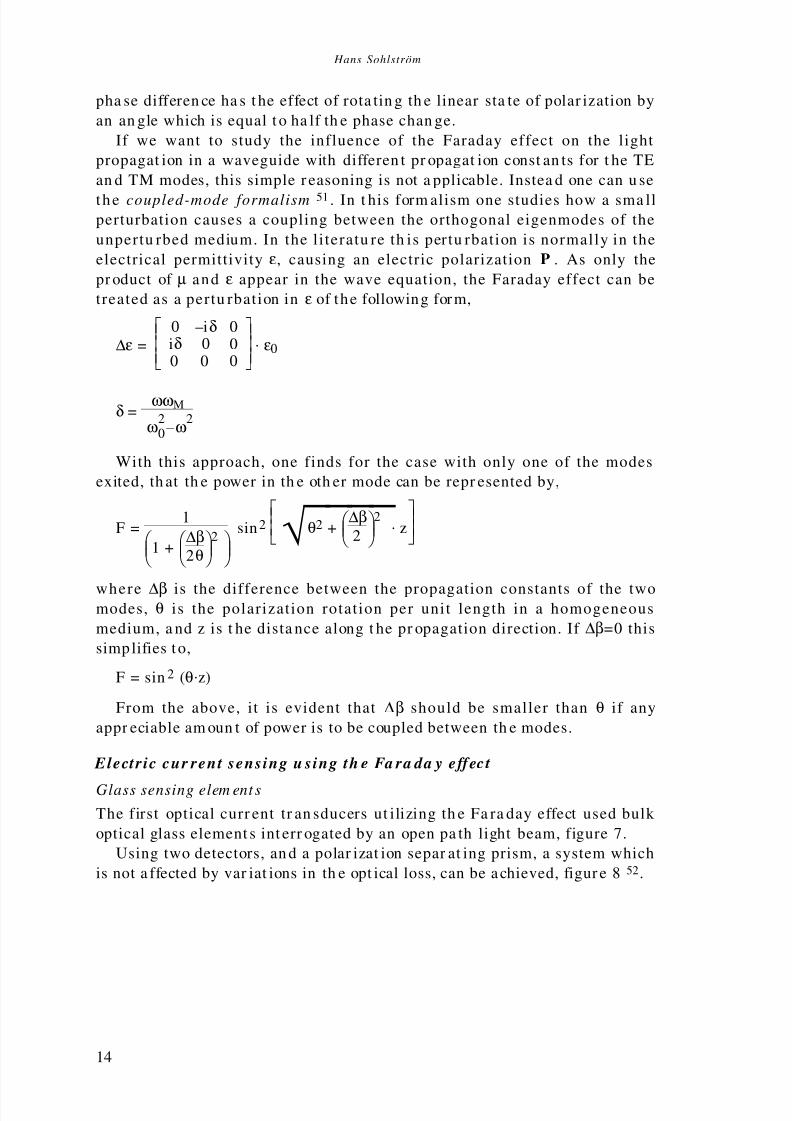
If we want to study the influence of the Faraday effect on the light
propagat ion in a waveguide with differen t pr opagat ion const an ts for t he TE
an d TM modes, this simple r easoning is not a pplicable. Instea d one can u se
the coupled-mode formalism51 . In t his form alism one studies how a sma llperturbation causes a coupling between the orthogonal eigenmodes of the
unpertu rbed medium. In the literatu re th is pertu rbation is normally in the
electrical permittivity ε, causing an electric polarization P . As only the
pr oduct of µ and ε appear in the wave equation, the Faraday effect can be
treated as a pertu rbation in ε of the following form,
∆ε =
0 –iδ 0
iδ 0 00 0 0
.ε0
δ=ωωM
ω20–ω2
With this approach, one finds for the case with only one of the modes
exited, th at th e power in th e oth er mode can be repr esented by,
F=1
1+
∆β
2θ2
sin2
√ θ2+
∆β
2
2 .z
where ∆β is the difference between the propagation constants of the twomodes, θ is the polarization rotation per unit length in a homogeneous
medium, a nd z is t he dista nce along t he pr opagation direction. If ∆β=0 this
simp lifies to,
F= sin 2 (θ.z)
From the above, it is evident that ∆β should be smaller than θ if any
appr eciable am oun t of power is to be coupled between th e modes.
Electr ic cur rent sensing u sing th e Fa ra da y effect
Glass sensing elem ent s
The first optical curr ent tr an sducers ut ilizing th e Fa ra day effect used bulk
optical glass element s int err ogated by an open pa th light beam, figure7.
Using two detectors, an d a polar izat ion separ at ing prism, a system which
is not a ffected by var iat ions in th e opt ical loss, can be achieved, figur e852.

8/3/2019 Fiber Optic Magnetic Field Sensors
http://slidepdf.com/reader/full/fiber-optic-magnetic-field-sensors 25/86
Fibre Optic Magn etic Field S ensors Utilizin g Iron Garn et Materials
15
I
θ
B
E
Polarizer
Polarizer
P0
P=P 0 cos2(θ–π /4)
Fig.7. The simp lest form of an optical current sensor utilizin g the Faraday
effect.
Polarizer
Det.
Det.
Laser
I
B
Polarizationsplitter
Fig.8. A bu lk optic current m easurem ent system with polarization stat e
detection. As the Faraday effect is non-reciprocal the two-way pass through
the sensing element effectively doubles the rotation.
The sensor is sensitive to the total magnetic field, thus, also to the
contributions from other conductors nearby. Also, the distance between the
condu ctor a nd t he sensin g element will influen ce th e scale factor. With t wo
sensing elemen ts, one on each side of th e condu ctor, a differen tia l system is
achieved, reducing th e influence from condu ctors a t large dist an ces.53
An iron core reduces the position dependence and the influence of exter-
na l fields, but a s th e iron core m ust ha ve a relat ively lar ge gap t o accomm o-
date the glass sensing element, some sensitivity to the conductor position
an d to exter na l fields will rema in.
A more funda ment al appr oach is to use a basic propert y of the m agnetic
field encircling th e conductor,
O∫ L
H.dl = ∫ ∫ S
i .ds = I
where i is the current density through the surface S, with the contour L,
and I is the total cur rent th rough S.
This means that if the sensing light path completely encircles the con-
ductor, fig 9, th e sensor becomes in sensitive to extern al fields an d indepen -
dent of the conductor position in the sensing element. This can be approxi-
ma ted with a bu lk sensing element with a centr al h ole for th e condu ctor or
sensing element assembled from several pieces of glass. The reflections at
th e corn ers m ust be suitably arra nged not to influence th e polarization st at e
of the light .54

8/3/2019 Fiber Optic Magnetic Field Sensors
http://slidepdf.com/reader/full/fiber-optic-magnetic-field-sensors 26/86
Hans Sohlström
16
Conductor
Polarizer
In
Polarizer
Ou t
Faradayrotatorelement
Fig. 9. A glass sensing element that encircles the conductor, after55
The early experiments were made with glass sensing element s ha ving
relat ively small Verdet const an ts, t ypically about 10–5 rad/A, requiring long
sensin g element s for good sen sitivity. Alth ough YIG (Y3Fe5O12 ) and other
ma ter ials with mu ch lar ger polar izat ion r ota tion were stu died56 , no tr ans-
ducers using such materials were presented. Multiple reflections were,
however, tried to reduce the physical size of the sensing element without
sacrificing optical p at h length57 ,58.
Devices to mea sur e both th e cur ren t a nd t he voltage simult an eously werealso presented.59,60
With optical fibres m an y of the pr oblems associat ed with th e open optical
pat h could be elimina ted 61. The possibilities with opt ical fibres, h owever, go
further than that. The sensing element can be made from an optical fibre.
Although the Verdet constant of the fibre material is not high, about
4.10 -6rad/A, a m easur able rotat ion can be achieved with a long fibre, and
with the fibre wound round the conductor, a good approximation of the
closed line in tegr al of the field is achieved.
There was a considerable interest in this type of device at the end of the
70’s a nd th e result s were pr omising62 . The bendin g of the fibre in th e coil,however, causes a temperature dependent l inear birefringence that
quenches the circular birefringence caused by the Faraday effect. Several
met hods ha ve been t ried t o overcome t his pr oblem.
If the fibre is twisted, a circular birefringence ”bias” is introduced, which
is magnetic field independent and large enough to quench the linear bire-
fringence. This bias birefringence is, however, temperature dependent63.
With the sensing fibre divided into sections with opposite twists, the bias
rotat ion a nd t he tem perat ur e dependence can be cancelled an d with t he use
of polar ization ma int ain ing fibre for t he downlead, the vibrat ion sen sitivity
is r educed 64. A similar a pproach is to use a fibre with a str ong birefringence
which is a lmost c ircular 6 5 . This c ircular birefringence is s trongly

8/3/2019 Fiber Optic Magnetic Field Sensors
http://slidepdf.com/reader/full/fiber-optic-magnetic-field-sensors 27/86
Fibre Optic Magn etic Field S ensors Utilizin g Iron Garn et Materials
17
temper at ur e dependent. Techn iques to compensa te for th is have, however,
been studied66.
The fibre can be woun d int o a coil in su ch a way th at th e beat length (th e
fibre length th at cau ses a ph ase differen ce of 2π between th e two ort hogona l
linear polarization modes) is equal to the circumference of the fibre coil.
When an external field is then applied to the fibre coil, the periodic mag-netic field t ha t is in th is way applied t o the fibre will cau se a n et polar iza-
tion rotation.67 ,68 ,69 . A principally similar scheme is to use a polarization
maintaining fibre with a very short beat length and arrange a periodic
ma gnetic field with t he sa me period70.
A more funda men ta l appr oach is to ann eal th e coiled fibre t o rem ove the
tempera tu re dependent linear birefringence71.
Also, the Faraday effect is temperature dependent. The use of a tempera-
tu re dependent linear ly birefringent optical element has been su ggested as
a way to introduce a temperature dependent part ia l quenching of the
Fa ra day effect, th ereby reducing the effective temper at ur e dependence72.In addit ion to th e simple polar ization detection syst em described above, a
number of interferometric systems to detect the polarization rotation has
been presented73 . Closed-loop systems7 4 and heterodyne detection
systems75 have been studied. A system for simultaneous measurement of
two currents has also been presented76 . To eliminate the influence of
reciprocal effects in the fibre, some of these systems utilize Sagnac in te r-
ferometers77 ,78 . The non-reciprocity of the Faraday effect also makes it
possible to use a Fabry-Perot resonat or to increase t he effective polar ization
rotation79.
Experiments with techniques to make the sensor output independent of
variations in the Verdet constant80 , or to convert the polarization rotation
to a spectr al modulat ion81, have been m ade.
Th e measurement bandwidth of Fa ra day sensors with bulk glass or fibre
coil sensing elements is limited by the transit time of the light in the
sensing element82,
B3dB=0.44τ =0.44.
cn
.1
2πr.
1N
where c/n is the speed of light in the fibre, N the number of turns in the
fibre coil and r is the radius of the fibre coil. With N=100, r=0.1 and n=1.5 a
bandwidth of 1.4MHz is achieved. Obviously, there is a trade-off between
sensitivity and bandwidth. With high pulsed currents the sensing element
can be mad e short, giving very lar ge bandwidth s. A nu mber of system s with
bulk glass83 or fibre sensing elements84 ,85 for measur ement of tran sient
curren ts in the 106A range have been presented. Other specialized
applications such as aerospace86 current measuring and space plasma
current measurements87 have been studied. There is also a potential for
distr ibuted m agnet ic field sensing88.
Alth ough t he u se of an optical fibre coil for cur ren t m easu rem ent s ma y in
principle seem straightforward, the practical application of the technology

8/3/2019 Fiber Optic Magnetic Field Sensors
http://slidepdf.com/reader/full/fiber-optic-magnetic-field-sensors 28/86
Hans Sohlström
18
is, however, complicated by the linear birefringence of the fibre and many
optical cur ren t m eterin g devices th at ar e insta lled in th e high volta ge power
lines ar e of the bu lk optical t ype89,90.
Other materials
Optical fibres with high Verdet constants may increase the applicability of cur ren t sen sing using fibre sensin g elemen ts. Terbium doped silica fibre91 ,
with a Verdet constant of 1.2.10–5 ra d/A, an d doped plast ic fibre92 , with a
Verdet const an t of 2.10–5 ra d/A, ha ve been developed.
The alt ern at ive solution is to use a compa ct sen sing element ma de from a
material with a Faraday rotation larger than that of the glasses. A small
sensor head is an advantage in many applications , including current
measur ement u sing an iron core.
BGO (Bi12GeO20)93 , BSO(Bi12SiO20)94,95 and ZnSe96 offer Verdet
constants of about 7.10–5 rad/A, which is about an order of magnitude
higher than that of the silica fibre material. Certain glasses also haveVerdet const an ts t ha t a re a lmost as h igh. A considera bly higher Verdet con -
stan t, about 2 .10–3 ra d/A, is achieved with Cd1–xMnxTe97 ,98 ,99 ,100,101 ,102.
YIG and substituted YIG offer polarization rotations which, for many
applications, is larger than that of Cd 1–xM nxTe by about an order of
magnitude. As YIG is a ferrimagnetic material, it can, however, not be
d irec t ly compared to the paramagne t ic and d iamagne t ic mate r ia ls
men tioned. Since YIG is th e ma ter ial chosen in t his work , it will be fur th er
described below.
YIG
YIG, Yttriu m iron garnet is a ferrimagnetic garn et crystal with t he composi-
tion Y3Fe5O12. It is transparent for light with a wavelength longer than
about 1.1µm. At 1.3µm and 1.5µm, wavelengths at which reliable light
sour ces an d det ectors ar e r eadily available, the optical loss is very low. YIG
has a substantia l Faraday rota t ion in large parts of the optical and
microwave spectrum. Crystals of optical quality can be grown from flux
melts or grown epitaxially on substrates. Epitaxially grown films can be
used as high quality optical waveguides exhibiting the Faraday effect10 3.YIG crystal material, often in the form of polished spheres, are used in
microwave components.
The crystal lattice of YIG is rhombohedral, almost cubic, with the iron
at oms occupying two different kinds of sites in t he lat tice, figur e10. For t his
reason th e form ula is sometimes writt en Y3+3 Fe
3+2 Fe
3+3 O
2–12 .
The magnetic properties of the crystal are mainly determined by the iron
atoms. The iron atoms in the two kinds of sites interact antiferromagneti-
cally with each other, giving a net magnetic moment equal to that of one
atom. The Yttrium is magnetically polarized by the field from the iron
at oms, but it h as litt le influence on t he str ength of th e magnet ic int era ction.

8/3/2019 Fiber Optic Magnetic Field Sensors
http://slidepdf.com/reader/full/fiber-optic-magnetic-field-sensors 29/86
Fibre Optic Magn etic Field S ensors Utilizin g Iron Garn et Materials
19
Y3+, etc.
O2–
Fe3+, etc.
Tetra hedral site
Octah edral siteDodecah edra l site
Fig.10. The different kin ds of atom ic sites in Y IG, after 106 .
Fig.11. Qualitative behaviour of the different contributions to the net m agnetization of rare earth garnets havin g a com pensation point . From 107 .
This is evident from t he fact t hat all rare-earth iron garnets (RIG, R3Fe5O12
where R is a rare earth) have a Curie temperature of about 550K 104. The
Curie temperature is the temperature a t which the thermal agita t ion
breaks down t he ma gnetic ordering of the at oms a nd t he ma terial ceases to
be ferromagnetic . The Curie temperature can therefore be used as a
measur e of the str ength of th e magnetic int eraction. The Curie temperat ur e
for pure YIG is 559K105. The net magnetic moment for the rare earth
garnets is, however, influenced by the rare earth, in several cases giving
compensation points, where th e temperat ure dependent magnetic moments
of the different kinds of atoms cancel each other at a specific temperature,
figur e11. YIG, however , does not h ave any compens at ion point .
It is possible to substitute part of the yttrium with other rare earths,
giving mixed rar e eart h garnet s. Also, oth er su bstitut ions can be made, but
th is norm ally has little effect on t he ma gnetic inter action. Bismut h su bsti-
tution is an exception as it increases the strength of the magnetic inter-
action, th ereby increasing th e Curie tem perat ur e.
If the iron is subst itut ed, the m agnetic int eraction is weaken ed, giving a
lower Curie temperat ur e.

8/3/2019 Fiber Optic Magnetic Field Sensors
http://slidepdf.com/reader/full/fiber-optic-magnetic-field-sensors 30/86
Hans Sohlström
20
Fig.12. Two-dim ensional d om ain pattern in thin sam ple with an out of plane anisotropy.
Th e lattice const an t of pure YIG is such that it can be epitaxially grown
on substrates of GGG, Gadolinium gallium garnet (Gd3 Ga 5O 12). Such
substrates of high quality are readily available. For substituted films, the
substitutions of the film and substrate must be combined to give the proper
lattice constants.
Th e magnetic anisotropy in pure YIG is mainly cubic and not so strong.Strain, however, strongly affects the magnetic anisotropy108. Epita xially
grown YIG films can, t her efore, ha ve easy directions of ma gnetization in th e
plane of the film, or perpendicularly to it, depending on the film strain
caused by the lattice mismatch. In addition to the strain anisotropy, there
can also be a growth-induced anisotropy, arising from a certain ordering of
th e ma gnetic ions in t he growth pr ocess.
Becau se of the ferrim agnet ic propert ies of the m at erial, volum es of equa l
direction of magnetization, so called magnet ic domains will form. The
domains are separated by thin Bloch walls where the magnetization
direction is changed. The domain size is determined by a magnetostaticenergy balance that depends on the material properties and the sample
geometry.
With thin bulk samples and epitaxia l ly grown fi lms with suitable
anisotropy, the domains can form two-dimensional patterns extending
th rough t he ent ire th ickn ess of th e film, figure12. Un der certa in condit ions
th is patt ern degenerat es to sma ll circular doma ins, bubbles . These bu bbles
can be moved ar oun d in th e film, creat ed and a nn ihilat ed by sma ll pertu r -
bations in the field. This is the phenomenon that was used in the bubble
memories, in which more than 1Mbit of information could be stored in the
form of a bubble pat ter n in 1cm 2 of iron ga rnet film 109.
For a large sample with m an y domains, t he a ctu al form of the individual
doma ins an d th eir movement when a n extern al field is applied seems t o be
stocha stic. For th e entir e sample or a large par t of th e sample th e beha viour
of the domains, however, averages out and the net magnetization reflects
th e varia tions in t he a pplied magnet ic field. There is h owever a t endency for
the domain walls to stick to imperfections in the material, such as lattice
dislocat ions, causing discont inuit ies in t he m agnet izat ion cha nge.
The dir ection of ma gnetizat ion of the individua l doma ins will also cha nge
8/3/2019 Fiber Optic Magnetic Field Sensors
http://slidepdf.com/reader/full/fiber-optic-magnetic-field-sensors 31/86
Fibre Optic Magn etic Field S ensors Utilizin g Iron Garn et Materials
21
under the influence of an applied field. The magnetic anisotropy will,
however, keep t he m agnetizat ion appr oxima tely along t he ea sy directions.
When the net magnetization of the sample cannot be adjus ted to the
external field through redistribution of the domains between the easy
directions only, a rotat ion of th e ma gnetizat ion dir ection within t he domains
will occur. For a very strong applied field, the magnetization will becompletely aligned with the field.
The rapidity with which the magnetization of the materia l can be
changed is limited by the dynamic properties of the domain wall move-
ments. This gives an upper frequency limit somewhere in the 10MHz to
GHz ran ge11 0. Very little work has however been done in measuring the
frequen cy res ponse of YIG ma teria l based devices111.
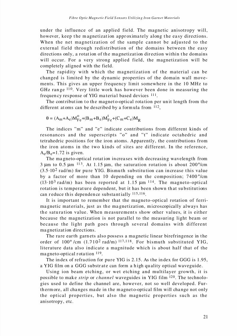
The cont ribut ion t o th e magnet o-optical rota tion per un it length from th e
different at oms can be described by a form ula from 112,
θ = (Am+Ae)MoFe+(Bm+Be)MtFe+(Cm+Ce)MR
The indices ”m” and ”e” indicate contributions from different kinds of
resonances and the superscripts ”o” and ”t” indicate octahedric and
tetrahedric positions for the iron atoms. Apparently, the contributions from
the iron atoms in the two kinds of sites are different. In the reference,
Ae /Be=1.72 is given.
The ma gneto-optical rotat ion in crea ses with decreasin g wavelength from
3µm to 0.5µm 11 3. At 1.15µm, the saturation rotation is about 200° /cm
(3.5.102rad/m) for pu re YIG. Bismu th substitu tion can in crease t his value
by a factor of more than 10 depending on the composition; 7400 ° /cm(13.103 rad/m) has been reported at 1.15µm 114 . The magneto-optical
rotation is temperat ur e dependent, but it has been shown th at su bstitut ions
can r educe th is dependen ce substa nt ially115,116.
It is important to remember that the magneto-optical rotation of ferri-
ma gnetic mat erials, just as th e ma gnetization, m icroscopically always has
th e satu ra tion value. When m easurement s show other values, it is either
because the magnetization is not parallel to the measuring light beam or
because the l ight path goes through several domains with different
ma gnetizat ion directions.
The ra re ear th garn ets also possess a ma gnetic linear birefringence in t heorder of 100° /cm (1.7.10 2rad/m)117,118 . For bismuth substi tuted YIG,
literature data also indicate a magnitude which is about half that of the
ma gneto-optical r ota tion119.
The in dex of refraction for pu re YIG is 2.15. As t he in dex for GGG is 1.95,
a YIG film on a GGG substr at e can form a h igh qu ality optical waveguide.
Using ion beam etching, or wet etching and multilayer growth, it is
possible to mak e strip or channel waveguides in YIG film120. The technolo-
gies used to define the channel are, however, not so well developed. Fur-
th erm ore, all cha nges ma de in t he m agnet o-optical film will cha nge not only
the optical propert ies , but a lso the magnetic propert ies such as theanisotropy, etc.

8/3/2019 Fiber Optic Magnetic Field Sensors
http://slidepdf.com/reader/full/fiber-optic-magnetic-field-sensors 32/86
Hans Sohlström
22
3. Star t ing point s for the sen sor development work
A conclusion from t he a bove descript ion of YIG an d other ra re ea rt h gar net s
is that they, compared to other magneto-optical materials , have many
favourable features such as a large magneto-optic rotation, well-defined
magnetic properties and good optical quality in the near IR. Furthermore,
particularly with the epitaxially grown films, many of these properties can
be a l tered a t wil l through a number of substi tut ions . Unfortunately
however, some of the propert ies are interl inked, mainly through the
mechanical strain, in such a way that they cannot easily be independently
optimized. We have, therefore, not considered it fruitful to design any
devices based on a ”perfect” ma gneto-optical ma ter ial th at ha s not yet beendeveloped. Inst ead, our appr oach ha s been to find device str uctur es tha t a re
useful for a demonstration with existing mat erials or with r elatively simple
modifications of known compositions. For similar reasons, no experiments
have specifically been made to measure the bandwidths of the experimental
sensors. No evidence of bandwidt h limita tions h as, h owever, been foun d in
mea sur ement s of ma gnetic fields at frequen cies up to about 1MHz.
The most st rikin g feat ur e of th is type of ma ter ial for sen sors, is th e large
Fa ra day r ota tion. To achieve a polarizat ion r ota tion of 90° (or a complete TE
to TM conversion in th e waveguide case) at 1.3µm, from less tha n 1 mm to
about 6 mm of optical pat h length is needed, depending on t he m at erial inquest ion. The volume of th e sensing elemen t can, t hu s, be ma de very small,
in the order of 1mm 3. With a sensing volume of this size, the spatial
variations of the magnetic field can be resolved. This is in contrast to the
sensors using glass sensing elements. They often require a large sensing
element and/or a closed measur ement path .
In t he design of a measur ement system t hat ut ilizes a YIG or su bstitut ed
YIG sensing element either in the form of a bulk crystal or a waveguide,
there are a number of system design options. To be able to choose between
these, we had to acquire a thorough knowledge of the properties of the
ma ter ial. As the available litera tu re dat a, relevan t for t his applicat ion, wereinsufficient, th is knowledge had t o be gained t hr ough m easur ement s.
For the single mode sensors we have, in order to avoid alignment
problems, decided to work with waveguiding sensing elements only. The
relatively large index difference between GGG and YIG, however, poses
some pr oblems. Guides tha t a re single mode in th e near infra red r egion a re
very th in, less tha n 1µm. A slab guide of this kin d will have a la rge linear
birefrin gence th at prevent s th e TM–TE conversion.
A num ber of techniques h ave been u sed to solve this pr oblem. Multilayer
structures with a layer between the GGG and the iron garnet film have
been investigated121. A ma gnetic field th at shifts its dir ection with a periodth at is equal to the beat length between t he TE an d TM modes can a lso be

8/3/2019 Fiber Optic Magnetic Field Sensors
http://slidepdf.com/reader/full/fiber-optic-magnetic-field-sensors 33/86
Fibre Optic Magn etic Field S ensors Utilizin g Iron Garn et Materials
23
used. In th is way, a net conversion can be obtain ed even with a relat ively
large ∆β122.
At a n ea rly st age of our project a per iodic cover st ru ctu re in GGG on t op
of the YIG waveguide was suggested a s a mea ns t o achieve a n et conversion
with a sin gle mode YIG waveguide123 .
We have, however, used another approach. Because of the high opticalqua lity of the YIG waveguides, th e coupling between th e differen t modes in
a mu ltimode guide is n egligible for th e pr opagat ion distan ces in qu estion.
As it is also possible to achieve a fibre to waveguide coupling that only
excites t he funda men ta l mode of the wa veguide, a r elatively th ick guide can
effectively be used for single mode use124. For t he fundam enta l mode, th is
kind of guide has a relatively small ∆β th at can be can celled by a modera te
strain-induced ∆β introduced during the film growth125 . The magnetic
propert ies of th e film ar e also influen ced by th e str ain n ecessar y to achieve
a small net ∆β but it is possible to achieve a usable device with this
approach.Some of th e cr itical design decisions t hen were:
• To use or not to use a ma gnetic bias field.
• One fibre for sending light t o the sensing element and for r eceiving the
signa l, or separ at e fibres for th e t wo fun ctions.
• The selection of a suita ble optical configurat ion th at a llows a measur able
polarization modulation and an acceptable optical loss. A channel
waveguide structure or a slab guide combined with some other means of
cont rolling th e light propagat ion ar e two of the options for th is pur pose.
The available selection of film types for waveguiding sensors was quitesma ll. The YIG films wer e origina lly developed for bubble mem ory u se a nd
have later been modified for use in display units , printers126,12 7, wave-
guiding optical isolat or s128 an d sensors.
For t he m ultimode sensors, which ar e of a m ore imm ediat e interest from
th e app licat ion p oint of view, a design which is suit able for production mu st
be selected.
In the mult imode case a larger se lection of useful materia ls was
available. The bulk YIG ma ter ial th at we initially used for th e mu ltimode
sensors was originally produced for microwave applications and had to be
cut and polished to optical quality. Later when the thick (≈100µm) epitaxi-ally grown films with lar ge ma gneto-optical rota tion were developed, ma inly
for optical isolat or use, we could u se t his t ype of mat erial for th e mu ltimode
sensors.
As th e mat erial char acterizat ion m easur ements went on, we were gra du-
ally able to tr an sform th e original sensor ideas envisioned at th e sta rt of th e
project, into practical sensor designs. In reality, of course, the influence also
went the other way: The sensor design ideas m ade fur ther measur ements
necessary. Below, however, the material characterization measurements
and th e sensor prototype experiments a re pr esent ed in separa te sections.

8/3/2019 Fiber Optic Magnetic Field Sensors
http://slidepdf.com/reader/full/fiber-optic-magnetic-field-sensors 34/86
Hans Sohlström
24
4. Material cha ra cter izat ion measu rements
Bulk materials
Mea surem ent opt ions
The magnetic and ma gneto-optical measu rement s th at can be made on bulk
YIG crystals can be divided into two categories, those made on homoge-
neously m agnetically satu rated samples and those made on non-saturated
samples. Microscopically, the saturated state is the only one that exists and
macroscopically, it is the only well-defined state. Examples of phenomena
that are studied are the influence of material composition, temperature,
wavelength, etc. on the saturation rotation. Such measurements are of
interest not only from an application point of view, but also for material
science, as t hey provide inform at ion a bout th e nat ur e of th e magn etic int er -
actions. Results from these types of measurements are, however, relatively
well covered in litera tu re, an d will not be fur th er described here.
For sensor applications, the properties of YIG also at low applied fields
are of interest. These include the domain structure and how it is influenced
by the crys ta l orienta t ion, sample geometry, sample treatment and
temperature.
Some measurements such as the measurement of the net magnetization
of the sample and its dependence on external factors, can be made using
ma gnetic methods129. Most of these r esults can , however, also be indir ectly
obtained from m agneto-optical measu rement s an d as our main interest is in
the magneto-optical properties, this is the approach we have taken. The
optical meth ods a lso facilitat e cha nges of th e mea sur ement volum e, which is
a key measurement par ameter.
If the sample is thin and the domains are large enough, a focused light
beam , figure13a, a llows t he beh aviour of a sin gle domain or doma in wa ll tobe studied. Ideally, with a beam passing through only one domain, one
should obtain the same results as those obtained for a homogeneously
saturated material. One can then study changes in the domain magneti-
zation direction and the effect on the magnetization and magneto-optical
rota tion cau sed by, for example, temper a tu re.
With a large diameter beam , figure13 b, the contributions from the
different domains will be averaged. The exact nature of the averaging
process is rather complicated as the pattern of the domains will act as a
phase grat ing. For a t hin sam ple with a t wo-dimensional doma in pat tern as
in figur e13, the r esulting polar izat ion rotat ion can often be appr oxima tedusing th e area r at io between th e two kinds of doma ins.

8/3/2019 Fiber Optic Magnetic Field Sensors
http://slidepdf.com/reader/full/fiber-optic-magnetic-field-sensors 35/86
Fibre Optic Magn etic Field S ensors Utilizin g Iron Garn et Materials
25
E
B
θ
Measurement object
I1=I 0cos2 θ
I2=I 0sin 2 θ
I0
Fig.14. Measurement system principle.
Fig.13 a. S m all m easurem ent v olum e.
Fig.13 b. Large m easurem ent volum e.
Mea sur emen t set-up
To stu dy the m agneto-optical pr operties of bulk m at erials, a mea sur ement
system according to the principle shown in figure14 has been used.
Linearly polarized light is sent th rough th e measu rement object. The beam
tr an smitt ed by th e measur ement object h as its plane of polarisat ion r ota ted
by an an gle θ. In a polarizat ion splitt ing Wollaston pr ism, th e beam is split
into two orthogonal polarization components with the intensities I 1 and I2.
Fr om t hese two values, an d the input intensity I0, the polarization rotation
an d t he optical loss of th e ma ter ial can be calculat ed.
Other polarization detection principles such as the use of polarization
modulation or rotating analysers are also possible130 . The simple two-
detector system was chosen mainly because it was also adaptable for
evaluat ion of sensor p rototypes.
The holder for the measurement object was temperature controlled and
surrounded by coils allowing a magnetic field of arbitrary direction to be

8/3/2019 Fiber Optic Magnetic Field Sensors
http://slidepdf.com/reader/full/fiber-optic-magnetic-field-sensors 36/86
Hans Sohlström
26
Polar izer Polar izerYIG
sampleIR vidiconor arr ay
Lens
Fig.15. Dom ain visualizin g set-up.
Fig.16. Magneto-optical rotation versus the applied magnetic field for a
2× 2× 2mm YIG cube as m easured w ith a 200µ m diam eter light beam withλ =1.15µ m .
generated. To allow automatic calibration and measurement routines, thesystem wa s designed with compu ter ized cont rol and da ta acquisition.
For a qualitative display of domain patterns, a set-up according to
figure15 was u sed.
Mea surem ent resul ts
Large measurem ent volum e
Our first measu remen ts of th e ma gneto-optical rotat ion versus th e applied
field were made with a 200µm diameter l ight beam through a cube
2×2×2mm of YIG, figure16. This rather discouraging result was, however
soon supplemented with other results indicating t hat a larger light beamdiameter and sample annealing improved the results , cf. the prototype
sensor r esults below.

8/3/2019 Fiber Optic Magnetic Field Sensors
http://slidepdf.com/reader/full/fiber-optic-magnetic-field-sensors 37/86
Fibre Optic Magn etic Field S ensors Utilizin g Iron Garn et Materials
27
We also found that a thinner sample with a two-dimensional domain
structure gave a more reproducible result, though at the cost of a lower
rota tion, about 5° for a single pass t hr ough a 0.3mm YIG slice.
Later, however, epitaxially grown Bi-substituted thick YIG films giving
22.5° rota tion in a 0.13mm film becam e available. The domains in t his type
of film a re also sma ller, giving a more efficient avera ging effect. Th e well-controlled growth conditions for these films should also give a smaller
nu mber of defects wh ich sh ould allow th e doma in wa lls to move more freely.
S m all measurem ent volum e
When a 0.13mm thick (YbTbBi)IG film on a GGG substrate is observed in
the IR through suitably arranged polarizers in a se t-up according to
figure15, a two-dimensional domain pattern is observed. The average
domain width is in the order of 12µm. The application of an external
magnetic field changes the area ratio between the two kinds of domains,
figure17a,b. At high field levels, close to saturation, the majority of thesmall domains disappear, leaving a pattern with a lower spatial periodicity,
figure 17c. For this specific material, the remaining domains shrink to
bubble-like form just before sat ur at ion, figur e 17d.
When measu remen ts on mat erials of th is kind a re to be interpr eted, one
should remember that the periodic domain structure will work as a phase
grating for th e light component with a polarization stat e th at is perpendicu-
lar to that of the input beam. Fig 17e,f,g show examples of diffraction
patterns obtained with the (YbTbBi)IG film for similar conditions as those
used for 17a,c,d. The diffraction patterns have been recorded with a set-up
similar to the one in figure15, though with the camera focused on infinity,i.e. the light source. The second polarizer is set to block the central beam
when no field is applied. The central beam is, however, not completely
extinguished in 17e. With field applied, the central beam will have its
polarisat ion r ota ted, and it will thus pa ss th e second polar izer an d sat ur at e
th e CCD arr ay. The polar ization of the diffra cted light is a lways perpendic-
ular t o th at of th e input beam.
Fig. 17a. Dom ains in 0.13m m
(YbT bBi)IG film with no external
field applied. Picture height
corresponds to 0.54m m .
Fig. 17e. Diffraction from a d omain
pattern lik e the one in 17a. T he
diffraction angle is approxim ately
2.6 ° , corresponding to a domainwid th of 12µ m .

8/3/2019 Fiber Optic Magnetic Field Sensors
http://slidepdf.com/reader/full/fiber-optic-magnetic-field-sensors 38/86
Hans Sohlström
28
Fig. 17b. Dom ains in 0.13m m
(Y bTbB i)IG film with 50m T applied
perpendicularly to the film . Th e do-
m ain pattern is nearly unchan ged.
Only the wid th ratio has changed.
Fig. 17c. Dom ains in 0.13m m
(Y bTbB i)IG film with slightly less
than 100m T ap plied perpend icu -
larly to the film . S ome of the do-
m ains from a an d b are still visible.
Fig. 17f. Diffraction from dom ain
pattern sim ilar to the one in 17c.
First order diffraction at 1.6 ° ,
ind icating a domain width of 20µ m .
S econd order d iffraction just visible.
Fig. 17d. Domains in 0.13mm
(Y bTbB i)IG film with about 100mT
applied perpend icularly to the film .
Fig. 17g. No diffraction is observed
wh en all d om ains ha ve disappeared.

8/3/2019 Fiber Optic Magnetic Field Sensors
http://slidepdf.com/reader/full/fiber-optic-magnetic-field-sensors 39/86
Fibre Optic Magn etic Field S ensors Utilizin g Iron Garn et Materials
29
Fig.19. Polarization rotation as m easured w ith a 30µ m diam eter beam
scann ed across a 0.3m m th ick Y IG sam ple. App lied field perpendicular toslice plane 33m T . Measured at 20° C and 100° C.
a) b)
Fig.18. Dom ain p atterns in 0.3m m slice of pure Y IG.
a)with no external field applied.
b) with a m agnetic field applied perpend icularly to the plane of the sam ple.
Similar resu lts obtained with a 0.3mm YIG slice ar e shown in figure18.
The avera ge doma in width is, in t his case, in t he order of 0.1mm.To get m ore qua nt itat ive results we used t he above ment ioned measu re-
ment system with t he beam focused down to a diameter sm aller t han th e
doma in width. Results a s th e one in figure19 were t hen obtain ed.
In this figure, the domain structure at two different temperatures is
shown. It can be seen that both the rotation within the domains and the
doma in pa tt ern differ. The polarization rotat ion in each domain is sm aller
a t the higher temperature . Our measurements of polarization rota t ion
versus magnetic field over a larger volume, however, show an increase in
th e sensitivity (dφ /dB) with t empera tu re. This can be explained by a sat u -
ration field H s th at decreases with increasing tempera tur e. These results ,th at ar e both in agreement with work published by oth ers, indicat e a way to
reduce the temperature dependence of sensors made from YIG and
substitut ed YIG mat erial131 .

8/3/2019 Fiber Optic Magnetic Field Sensors
http://slidepdf.com/reader/full/fiber-optic-magnetic-field-sensors 40/86
Hans Sohlström
30
Monitor orcomputer
CCD arrayPolarizer
Laser1152 n m
SamplePolarizer
Fig.20. Experim ental set-up for the grating based m easurem ent s
Sensor des ign cons idera t ions
From the measurement results , we were able to draw some conclusions
concern ing how to design sen sors bas ed on bu lk YIG crysta ls:
• A th in crystal with a one-layered domain pat tern , simplified the ana lysis
an d gave good resu lts, th ough a t t he cost of a r educed rota tion.• A probing light beam m uch wider tha n th e domain size, and preferably
covering a large part of the crystal surface, reduced the effect of single
doma in behaviour .
• Annealing the crystal after sawing and polishing improved the r esults .
Waveguides
Mea surem ent opt ionsMost of the magneto-optical measurements on waveguiding samples are,
principally, s imilar to those made on bulk samples. The situation is ,
however, complicated by the role of the linear birefringence. Furthermore,
th e cases differ in th e mean s by which t he light is coupled into an d out of
the material. For the waveguide characterization measurements, methods
based on holographic grating, prism and end-fire light coupling, have been
used.
The grating based method was used to determine accurately the linear
birefringence and the saturation value of the magneto-optical rotation. In
th ese measur ement s a grat ing, which is form ed in photoresist on top of thewaveguide, works as a distribut ed light coupler. A sketch of the m easur e-
men t set -up is sh own in figur e20.
The sample is turned to the coupling angle corresponding to the mode to
be studied. As the coupling angle is, within the divergence of the laser
beam, th e same for t he TE a nd TM modes of th e same order, a polar izer an d
a retarder can be used to excite an arbitrary state of polarization at the
input point. As the light propagates along the guide, a small fraction will
cont inu ously be coupled out , allowing th e evolut ion of the int ensity a nd th e
polarizat ion st at e to be studied.
To determ ine th e linear birefringence and t he m agneto-optical r ota tion,

8/3/2019 Fiber Optic Magnetic Field Sensors
http://slidepdf.com/reader/full/fiber-optic-magnetic-field-sensors 41/86
Fibre Optic Magn etic Field S ensors Utilizin g Iron Garn et Materials
31
TM
TM
TE
Rutileprisms
Fig.21. Prism coupling m ethod.
the spatial distributions of the outcoupled light under different magnetic
field a nd input polar izat ion condit ions is r ecorded132
.Even th ough t he grat ing method can be used to measure t he polar izat ion
rotation under different magnetic field conditions, it is more convenient to
use t he pr ism coupling meth od to study t he varia tions in th e rotat ion once
th e satur at ion value is determined.
A prism with an index of refraction equal to or higher than that of the
guide is brought into contact with the guide by mechanical pressure,
figure21. Light impinging on the prism–guide interface with a suitable
an gle can th en couple t o a waveguide mode. Similar ly, light can be coupled
out through a second prism. For YIG waveguides, rutile is a suitable prism
ma ter ial. As ru tile is birefringent, t he TE a nd TM modes will have differen tcoupling angles. With only one of the polarization modes excited at the
input , th e fraction of light convert ed can ea sily be monitored u nder different
magnetic field conditions. Just as in the bulk measurement case, we have
used a computer controlled measurement se t-up to provide re levant
ma gnetic field var iat ions.
A number of experiments were also made with the fibre end coupled
directly to the waveguide edge (butt-coupled). This method, in contrast to
the prism method, does not involve any mechanical perturbation of the
sample during the measurement . On t he other han d, the samples must be
specially prepar ed with polished edges.
Resul t s o f the w aveguide measur ements
The gra tin g based meth od was u sed in an ear ly sta ge of th e project t o select
sam ples with su fficiently sma ll linea r birefrin gence to allow a la rge TE–TM
mode conversion in the fundamental mode. Most of the samples we have
used allowed a conversion of 90% or more. The results shown in this
summary, except where is otherwise indicated, are obtained with 6.4µm
thick samples of Gd,Ga substituted YIG film on GGG substrate with a
saturation polarization rotation of 150° /cm (2.6.102rad/m) at λ=1.15µm.
This m at erial wa s kn own t o be ”easy in pla ne”, i.e. th e ma gnetizat ion of the

8/3/2019 Fiber Optic Magnetic Field Sensors
http://slidepdf.com/reader/full/fiber-optic-magnetic-field-sensors 42/86
Hans Sohlström
32
Fig.22. TM to TE m ode conversion versus a m agnetic field applied in the
plane of the film and parallel to the light p ropagation d irection. Th einteraction length was 4m m .
Fig.23. TM to TE conversion, m easured th rough a bu tt-coup le fibre, versus
the m agnetic field applied in th e plane of the film and parallel to the light
propagation d irection. T he param eter is the pressure applied t o the coup ling prism.
film could move relatively easily in the plane of the film but could not easily
be tur ned from t he plan e of th e film133,134.
Our f irs t results with prism coupling seemed, jus t as in the bulk
measurement case, somewhat discouraging, figure22. With a 50µT field
applied parallel or anti-parallel to the light propagation direction, the
conversion is ra th er h igh an d between t hose two extrem es, the conversion
goes down. There is, however, a large hysteresis, and the magnetization
appar ently chan ges in steps.We foun d th at th e mecha nical waveguide str ain indu ced by th e pressure
applied to the prisms was responsible for part of the hysteresis. This is
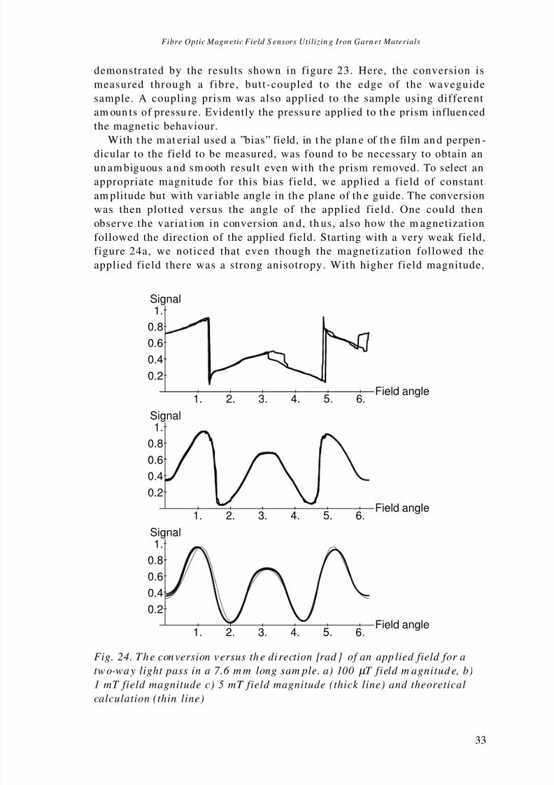
8/3/2019 Fiber Optic Magnetic Field Sensors
http://slidepdf.com/reader/full/fiber-optic-magnetic-field-sensors 43/86
Fibre Optic Magn etic Field S ensors Utilizin g Iron Garn et Materials
33
1. 2. 3. 4. 5. 6.Field angle
0.2
0.4
0.6
0.8
1.Signal
1. 2. 3. 4. 5. 6.Field angle
0.2
0.4
0.6
0.8
1.Signal
1. 2. 3. 4. 5. 6.Field angle
0.2
0.4
0.6
0.8
1.Signal
Fig.24. The conversion versus th e di rection [rad ] of an app lied field for a
two-way light pass in a 7.6m m long sam ple. a) 100µ T field m agnitud e, b)
1mT field magnitude c) 5mT field magnitude (thick line) and theoreticalcalculation (thin line)
demonstrated by the results shown in figure23. Here, the conversion is
measured through a fibre, butt-coupled to the edge of the waveguide
sample. A coupling prism was also applied to the sample using different
am oun ts of pressu re. Evidently the pressu re applied to th e prism influen ced
the magnetic behaviour.
With t he m at erial used a ”bias” field, in t he plan e of th e film an d perpen -dicular to the field to be measured, was found to be necessary to obtain an
un am biguous a nd sm ooth result even with th e prism removed. To select an
appropriate magnitude for this bias field, we applied a field of constant
am plitude but with var iable angle in th e plane of th e guide. The conversion
was then plotted versus the angle of the applied field. One could then
observe the variat ion in conversion an d, th us, also how the m agnetization
followed the direction of the applied field. Starting with a very weak field,
figure24a, we noticed that even though the magnetization followed the
applied field there was a strong anisotropy. With higher field magnitude,

8/3/2019 Fiber Optic Magnetic Field Sensors
http://slidepdf.com/reader/full/fiber-optic-magnetic-field-sensors 44/86
Hans Sohlström
34
figure24b, we could observe how the magnetization direction more and
more closely followed the direction of the field. In figure24c, with a 5mT
field, the magnetization almost completely follows the direction of the
applied field. Although t her e ar e some deviat ions from t he t heoretical curve,
th e measu red curve is smooth an d free from hyster esis. This indicat es th at
the 5mT field was strong enough to create a single domain with ama gnetization which could t hen be rotat ed by th e field to be measu red.
In order to study the magnetic behaviour of a channel structure in the
film, experiments were made with strip waveguides delimited by parallel
slits sawn through the waveguiding film. The hysteresis problems were,
however, found to increase. A probable explanation is that the ”channel
str uctur e”, and t he r ough sa wn edges, affected t he domain st ru ctu re. Some
experim ent s with etching of YIG were a lso ma de135.
Sensor des ign cons idera t ions
Fr om m easu rem ent s such as t hose described above, we drew th e conclusionth at with th is type of mater ial, which wa s known to have a r elatively small
an isotr opy, a bias field of about 5mT was needed t o achieve a r eproducible
sensor behaviour .
The use of a bias field, however, limits the applicability of the sensor in
several ways. The bias field may disturb the measurement situation in an
un accepta ble way. If th e bias field is to be supplied by a per ma nen t m agnet ,
the effects of strong overload fields on this magnet must be considered. It
may also prove difficult to find a magnet material that maintains the bias
field constant over the temperature range required. On the other hand,
th ere is in principle also a possibility to use a t empera tu re dependent bias
field to partly compensate the temperature dependence of the sensor
material.
An alternative approach is, as will be shown below, to use a material
with a st rong anisotr opy.
Partly because of the results that were obtained in the channel wave-
guide experim ent s, and par tly becau se of the exten t of process developmen t
work necessar y to mak e cha nn el waveguide stru ctu res, we also decided to
us e slab guides only.
Pa per reference
The design an d perform ance of the m easurem ent system for bulk sam ples are
discussed in paperA. In t his paper, som e exam ples of result s are also given.
The results are more fully described in paper C, and the sensor design rules
are given in paper B.
The different w aveguide characterization m ethods and the role played by the
pressure applied to the prisms are covered in paper E.
The use of a variable in-plane field to select a suitable bias field, is
described in paper G.

8/3/2019 Fiber Optic Magnetic Field Sensors
http://slidepdf.com/reader/full/fiber-optic-magnetic-field-sensors 45/86
Fibre Optic Magn etic Field S ensors Utilizin g Iron Garn et Materials
35
GGG
Y IG
Fig.25. Basic sensing principle
5. Sensors.
Single-mode systems
The sensing element of a m easur ement system with polarization m aint ain-
ing single-mode fibres could, in principle, be either waveguiding or bulk
optical. To avoid alignment problems, we have decided to work only with
waveguiding sensing element s in our sin gle mode system s. With a t hickn ess
of 5–10µm, the sensing elements have been capable of carrying several
modes, but we have shown that it is possible to use them effectively assingle mode guides, but t-coup led to fibres.
The other two coupling methods that we have used in the characteriza-
tion work can also be used in sensor configurations. The prism coupling
method, however, lacks the ruggedness and potentially low cost that the
butt-coupling and grating methods have. While we have preferred the
simple butt-coupling in our sensors, grating coupling is a good alternative,
particularly for thinner guides which cannot be effectively butt-coupled to
fibres.
The basic principle of a waveguiding sensing element in combination
with p olar ization preser ving fibres is demonstr at ed in figur e25. One of th epolarization modes of the fibre is used to carry linearly polarized light
(white ar row) to the sensing element, where it is launched into th e fun da-
mental TE mode of the planar waveguide. In the waveguide, part of the
optical power is converted to the TM mode (graded arrows). The light is
th en coupled int o th e retu rn fibre, which is orient ed in such a way th at each
of the modes of the planar guide matches one of the fibre polarization
modes. At t he out put end of th e fibre, th e light from t he t wo fibre m odes is
separa ted a nd det ected. The detector output s ar e th en combined to give an
int ensity independent signa l tha t is a measu re of th e magnet ic field.
With this configuration it is not possible to detect the sign of the

8/3/2019 Fiber Optic Magnetic Field Sensors
http://slidepdf.com/reader/full/fiber-optic-magnetic-field-sensors 46/86
Hans Sohlström
36
0.4 mm
10 mm
Fig. 26. Two-fibre sensor with 3.7µ m Bi-substituted wa veguide.
ma gnetic field. Fields tha t a re pa ra llel to, or a nt i-par allel to th e light pr opa -
gation direction, cause TE to TM coupling factors that are equal in magni-
tu de an d, consequen tly, they cau se equal a mount s of light to be coupled int o
th e TM mode. However, if th e ret ur n fibre is mount ed with its birefringence
axes at ±45 ° to those of the waveguide, the amplitude in each of the fibre
modes will be a linear combination of the amplitudes of the TE and TMwaveguide mode fields leaving the waveguide, giving a suitable anti-
symmetric sensor behaviour. This is in analogy with a conventional bulk
optic polarization rotation measurement set-up with the analyzer rotated
45° or –45° from th e inpu t polar izer orienta tion.
The absence of a lateral light confinement leads to a severe light loss
when a configuration as the one in figure25 is used. The loss can be of
accepta ble size only if th e sensor is very short. Consequently, th ere is t hen a
tr ade-off between polarization rotat ion an d loss, but with ma teria ls having
a very large Faraday rotation, it is possible to find a useful compromise.
This is demonstra ted by the r esults obtained with a sensor using a sh ortbismuth-substituted YIG waveguide having a saturation magneto-optic
rotation of about 1000° /cm (1.7.103 rad/m) at 1.15µm, figure 26. This
waveguide had a str ong out-of-plane an isotr opy.
The idea was that this anisotropy should replace the bias field necessary
with the other waveguiding sensors. The sensor output versus the applied
field is shown in figur e 27. A hyst eresis effect appea rs for field magn itu des
less than 1mT. For such field levels, the magnetization direction is almost
perpend icular to th e film plan e. For larger field levels, th e perform an ce is as
expected , i.e. a smooth field vers us conver sion r elat ions hip. It is also evident
from th e non-symmetr y of the cur ve tha t t he r etur n fibre was n ot corr ectly
mounted, but was r ota ted slight ly off the int ended an gular position with its
birefrin gence axes at 45° from th ose of th e inpu t fibre. The im perfections of
th is experiment al pr ototype should, however, not conceal t he fact th at th e
design principle is working. With another material having a stronger
an isotr opy it ma y be a viable concept.

8/3/2019 Fiber Optic Magnetic Field Sensors
http://slidepdf.com/reader/full/fiber-optic-magnetic-field-sensors 47/86
Fibre Optic Magn etic Field S ensors Utilizin g Iron Garn et Materials
37
a)
Polarizationmaintaining fibres
YIG waveguide Mirrorededge
b)
Polarizationmaintaining fibre
YIG waveguide Mirrorededge
Fig.28. Configurations for waveguiding sensors with focusing reflectors.a) With tw o fibres. b) With one fibre.
Fig. 27. Sensor output versus th e applied field for a sensor accordin g to
figure 26.
An a ppr oach th at in ad dition to solving th e loss pr oblems also allows th einput and output fibres to be mounted side by side instead of in line on
opposite edges of the waveguide, is to make a focusing reflector on the
waveguide, figure28a. In th e experimen ta l sensors, th is reflector was m ade
by polishing th e rea r edge int o a semicircular form . A th in gold coat ing was
then applied. Etched waveguide mirrors or grating reflectors are alter-
na tives tha t could be ta ken int o considera tion. An experiment al pr ototype is
shown in figure 29.
As the Faraday effect is nonreciprocal in nature, the mode conversion of
the forward and backward trip will add, making the effective interaction
length t wice the sensing element length.
This is the single-mode sensor design for which we have recorded the
largest am ount of test dat a. Results obtained with a sensor prototype with a
7.6mm long Gd,Ga substituted YIG waveguide of the kind previously
men tioned, ar e shown in figur e 29. A bias field of 5mT was used accordin g
to th e sensor design considera tions in t he pr evious section of th e sum ma ry.

8/3/2019 Fiber Optic Magnetic Field Sensors
http://slidepdf.com/reader/full/fiber-optic-magnetic-field-sensors 48/86
Hans Sohlström
38
Fig.29. Experimental sensor according to fig 28a.
Fig. 30. Sensor outp ut versus the applied field for th e folded two-fibredesign. Bias field 5 m T perpend icular t o the axis of the sensin g elem ent .
The results show the expected sensor function with a central smooth
sensing ran ge and a slope reversa l at appr oxima tely ±2mT, figure30. This
indicates that the optical power couples back into the mode which it was
originally launched into, equivalent to a polarization rotation of more than
45°. A sensor with a shorter interaction length would give a monotonous
relationship.
Tests made with a spectrum analyzer, confirm the good signal quality
an d indicat e a det ector a nd a mplifier noise level equivalent to about 8nT in
a 1Hz ban dwidth with a 5mT bias field. The detection limit of th e sensing

8/3/2019 Fiber Optic Magnetic Field Sensors
http://slidepdf.com/reader/full/fiber-optic-magnetic-field-sensors 49/86
Fibre Optic Magn etic Field S ensors Utilizin g Iron Garn et Materials
39
Fig.31. Experim ental one-fibre sensor according to figure28b.
element is, thus, lower than this value. By increasing the bias field, the
mea sur ement ra nge can , of cour se, also be scaled t o higher values.
We have also made a sensor where th e same polar izat ion maint aining
fibre is used to guide the light both t o an d from t he sensin g element , figures
28b and 31. In s uch a configur at ion, th e 45° displacement of th e retu rn fibre
needed to a chieve directional discrim ina tion, is obviously n ot possible. Forsystems covering large distances, it is an advantage with only one fibre.
Typically, however, such systems will include discontinuities in the fibre,
e.g. removable connectors without index matching. Reflections from such
discont inuit ies will be a problem in a one-fibre system . The r eflected power
will interfere with the light returning from the sensing element. As the
pha se angle between th e unwa nt ed reflection a nd t he signal is deter mined
by the length of the optical path to the sensing element, which will vary
with t he environm ent, r apid am plitu de variat ions will ta ke place. Although
only one of the channels is affected, the performance of the balanced sensing
system can be severely degra ded.The optoelectronic unit needed in a one-fibre system is also much more
complex than the one in a two-fibre system. In addition to the polarization
splitter, an extra beamsplitter, to couple the laser light into the fibre, is
needed, figure 32. As th e light h as t o pass t his extra beamsp litter twice, th e
loss intr oduced is large. Fur th ermore, the r isk of stra y light from th e laser
falling on t he detectors is subst an tia l.

8/3/2019 Fiber Optic Magnetic Field Sensors
http://slidepdf.com/reader/full/fiber-optic-magnetic-field-sensors 50/86
Hans Sohlström
40
Fig. 33. Output signal from one-fibre sensor according to figure 28 b with an
optoelectronic un it according to figure 32. A bias field of 3mT in the plane of the waveguid e is used.
Laser diode1.3 µm
Polarizer
Beam-splitter
Wollastonprism
Detectors
Polarizationmaintaining fibre
Fig. 32. Optoelectronic un it for one-fibre sensing system .
Using a 1.3µm laser with short coherence length we have, however,
obta ined good r esults with a one fibre syst em wit h n o removable conn ectors
and with the fibre ends obliquely cut to avoid reflections, figure 33. The
sensing element is similar t o th e one u sed in th e two-fibre sensor. The non-
symmetry of the curve is, at least partly, due to the non-symmetry of the
sensing element cau sed by the oblique m oun ting of th e fibre.The systems described here are balanced, i.e., the sum of the optical
power from the two channels is independent of the measurand and only
dependent on th e system loss, while th e distr ibution of power between t he
two channels is ideally only dependent on the measurand. This is
complete ly true for the l ight path to the sensing e lement but only
approximately so for the path from the sensing element to the detectors.
Loss mechanisms that unequally affect the two fibre polarization modes in
th e retu rn fibre, will influence th e out put signal.
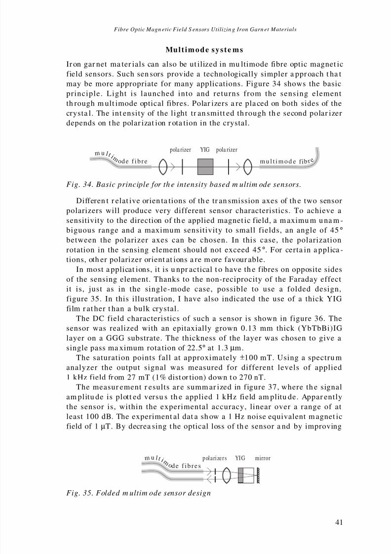
8/3/2019 Fiber Optic Magnetic Field Sensors
http://slidepdf.com/reader/full/fiber-optic-magnetic-field-sensors 51/86
Fibre Optic Magn etic Field S ensors Utilizin g Iron Garn et Materials
41
polarizer s YIG m u l t i m o de f i b res
mirror
Fig.35. Folded m ultim ode sensor design
Mult imode syste ms
Ir on gar net ma ter ials can also be ut ilized in mu ltimode fibre optic magnet ic
field sensors. Such sen sors provide a technologically simpler a ppr oach t ha t
may be more appropriate for many applications. Figure34 shows the basic
principle. Light is launched into and returns from the sensing elementth rough m ult imode optical fibres. Polar izers a re pla ced on both sides of the
crysta l. The int ensity of the light tr an smitt ed th rough th e second polar izer
depends on t he polar izat ion r ota tion in the crystal.
pola rizer pola rizerYIG m u l t i m
o de f i b re m u l t i m o d e f i b r e
Fig. 34. Basic principle for th e intensity based m ultim ode sensors.
Differen t r elat ive orien ta tions of th e tr an smission axes of th e two sensor
polarizers will produce very different sensor characteristics. To achieve a
sensitivity to the direction of th e applied magnet ic field, a m aximu m u na m -
biguous range and a maximum sensitivity to small fields, an angle of 45°between the polarizer axes can be chosen. In this case, the polarization
rotation in the sensing element should not exceed 45°. For certa in a pplica -
tions, oth er polarizer orient at ions a re m ore favour able.
In most a pplicat ions, it is u npr actical t o have th e fibres on opposite sides
of the sensing element. Thanks to the non-reciprocity of the Faraday effect
it is, just as in the single-mode case, possible to use a folded design,figure35. In this illustration, I have also indicated the use of a thick YIG
film r at her t han a bulk crystal.
The DC field characteristics of such a sensor is shown in figure36. The
sensor was realized with an epitaxially grown 0.13 mm thick (YbTbBi)IG
layer on a GGG substrate. The thickness of the layer was chosen to give a
single pass ma ximum rota tion of 22.5° at 1.3µm.
The saturation points fall at approximately ±100mT. Using a spectru m
analyzer the output signal was measured for different levels of applied
1kHz field from 27mT (1% distor tion) down to 270nT.
The measur ement r esults ar e summ ar ized in figure 37, where th e signalam plitu de is plott ed versu s th e applied 1kHz field am plitu de. Appar ently
the sensor is, within the experimental accuracy, linear over a range of at
least 100dB. The experiment al dat a sh ow a 1Hz noise equivalent m agnet ic
field of 1µT. By decrea sing t he optical loss of th e sensor a nd by improving

8/3/2019 Fiber Optic Magnetic Field Sensors
http://slidepdf.com/reader/full/fiber-optic-magnetic-field-sensors 52/86
Hans Sohlström
42
th e am plifier, a r eduction of th is value to 100nT sh ould be within rea ch.
The a ccur acy of this type of sensor is, in most cases, limit ed by th e loss
variat ions in t he system a nd by the t empera tu re dependence of th e sensor
ma ter ial. In some applicat ions, e.g. AC mea sur ement , th e avera ge value of
the mesurand is known. One can then compensate for the slow loss
variation. By optimizing the sensor material composition and thickness thetem perat ur e dependence of the m at erial can be r educed considera bly, less
th an 1% between –20°C and 80°C has been r eport ed136.
A recent prototype version of the multimode sensor is shown in fig38.
Oth er versions ar e shown in fig 39.
Fig. 36. The m agnetic field characteristics of a m ultim ode sensor wit h an
epitaxially grown 0.13 mm th ick (YbT bBi)IG layer on a GGG su bstrate.
APPLIED FIELD [dB RE 1 T]
S I G N A L [ d B R E S I G .
A T 2 7 m T ]
-120
-100
-80
-60
-40
-20
0
-140 -120 -100 -80 -60 -40 -20
1 Hz noise level
Fig. 37. Th e signal am plitud e versus the applied field.

8/3/2019 Fiber Optic Magnetic Field Sensors
http://slidepdf.com/reader/full/fiber-optic-magnetic-field-sensors 53/86
Fibre Optic Magn etic Field S ensors Utilizin g Iron Garn et Materials
43
Fig38. Prototype sensor developed for a field t rial in co-operation w ith AB B
Power S ystem s, with p rotective cover removed , lying on a p iece of paper with
m m rulin gs. a:YIG/ GGG sensin g elem ent w ith gold coating, b:grad ient
index lens, c:polarizers, d:fibre holder m ade from a p iece of glass t ube.
Fig39. Th ree versions of multim ode sensors with folded d esign
Pa per reference
The waveguiding sensors are first introduced in paper D. Results from an
experiment with a two-fibre unfolded system are shown, but the paper is
mainly about the one-fibre folded design according to figure27b in this
summary. Different techniques to avoid interference effects are also
described.
In paper F, a similar folded sensor is used but with an 1.3µ m sem icon -
ductor laser diode light source to reduce the interference problems. A sensor utilizing a very short piece of highly magnetically anisotropic Bi-YIG wave-

8/3/2019 Fiber Optic Magnetic Field Sensors
http://slidepdf.com/reader/full/fiber-optic-magnetic-field-sensors 54/86
Hans Sohlström
44
guide is also described. In the same paper there is also a description of a
nu m ber of m ultim ode sensors.
The two-fibre folded design sensor and its performance is treated in
paperG.
The perform ance of the folded m ultim ode sensor is treated in paper H.

8/3/2019 Fiber Optic Magnetic Field Sensors
http://slidepdf.com/reader/full/fiber-optic-magnetic-field-sensors 55/86
Fibre Optic Magn etic Field S ensors Utilizin g Iron Garn et Materials
45
6. Conclusions
Fibre optic magnetic field sensors based on iron garnet material have a
nu mber of favoura ble feat ur es. They can be ma de very compa ct, h ave lar ge
measu remen t r anges an d resolut ions in t he nT r egion. The small size is an
advantage not only for the point sensing of magnetic fields, but also for
cur rent measur ement t ogeth er with an iron core.
Both single-mode and multimode systems are demonstrated in this
th esis. The two types of system s differ both in th eir mea sur emen t possibili-
ties an d in more practical ha ndling aspects.
Using polar izat ion ma inta ining single-mode fibre an d sensing element s
made from few-mode YIG waveguide, several versions of balanced mea-sur ement system ha ve been built. The out put signa l from such a system is
appr oximat ely independent of the system loss. Sensors h ave been ma de both
with separ at e fibres to guide the light to and from th e sensing element a nd
with a single fibre for both functions. The two fibre version is, however, less
complicat ed and h as a bett er perform an ce.
While the waveguiding s ingle-mode sensors have some attractive
features and perhaps potentially the best performance, the multimode
sensors are less complicated to manufacture. As they can be produced at a
low cost, they could replace Hall elements, not only in magnetic field
sensors, but also for rotation speed sensing, etc. Also for electric currentmeasur ement th ey are a viable altern at ive. While an a ccur acy equal to tha t
of precision current transformers has not yet been demonstrated, sensor
prototypes suitable for other current monitoring applications in the electric
power grid have been developed.
The temperat ure dependence of the Fa ra day rotation which at present
limits the accuracy of the sensors can be substantially reduced with new
sensor m at erial compositions.
The renewed interest in magneto-optical ma terials ma y make suitable
sensor m at erials more r eadily available in t he near fut ure.

8/3/2019 Fiber Optic Magnetic Field Sensors
http://slidepdf.com/reader/full/fiber-optic-magnetic-field-sensors 56/86
Hans Sohlström
46
7. Acknowledgements
There a re a n um ber of persons who ha ve helped me dur ing the work .
Firs t I would l ike to express my grati tude to professor Kjell G.
Svantesson, who has been my supervisor and friend during the major and
last part of the work, for his constant support and encouragement. Also I
would like to thank professor Gunnar Brodin and professor Torgny
Brogårdh who have, for differen t per iods of tim e, been m y super visors.
I would also like to thank my co-worker Ulf Holm , not only for his
collaboration in the work and good advice, but also for the many almost
endless, but indeed fruitful, discussions about work and life in general.
Bengt Molin is not mentioned as a co-worker in the papers, but his helpwith the mechanical design and fabrication of the sensors and laboratory
equipment h as been very import an t, an d I would like to tha nk h im for t his.
In fact, I would like to thank the entire staff of the Instrumentation
Laborat ory an d a nu mber of oth er pers ons a t KTH, who ha ve all, in various
ways, helped me. Carolyn Kyrnin g, who ha s helped me to rem ove a nu mber
of language mistakes in the summary, should also be mentioned. New
err ors h ave, however, undoubtedly been a dded afterwa rds.
Finally, I would like to thank my wife and children for their support and
for making the thesis work possible by taking over a lot of responsibilities
during t he last months of intense work.The th esis is based on work support ed by th e Nat iona l Swedish Board for
Techn ical Development (STU).

8/3/2019 Fiber Optic Magnetic Field Sensors
http://slidepdf.com/reader/full/fiber-optic-magnetic-field-sensors 57/86
Fibre Optic Magn etic Field S ensors Utilizin g Iron Garn et Materials
47
References
1 J . Hecht, ”Victorian experiments an d optical commu nications”, IEEE Spectrum , p.69–
73, Febru ary 1985.
2 C. Menad ier, C. Kissinger a nd H . Adkin s, ”The fotonic sensor”, Instrum ents & Control
Systems, vol.40, p.114–120, 1967.
3 J . A. Powell, ”A simple t wo-fiber optical displa cement sens or”, Rev. Sci. Instru m .,
vol.45 no.2, 1974.
4 D. E. N. Davies and S. Kingsley, ”Method of phase-modulating signals in optical fibres:
Application to optical-telemetry systems”, Electronics Letters, vol.10, p.21–22, 1974.
5 J . A. Bucaro, H. D. Dar dy, E. F. Car ome, ”Fiber -opt ic hydrophone”, Journal of the
Acoustical S ociety of Am erica , vol.62, p.1302, 1977.
6 J . P.Dakin , D. A. Kah n, ”A novel fibre-opt ic tem pera tu re pr obe”, Optical an d
Quan tum Electronics, vol.9, p.540, 1977.
7 C. D. But ter an d G. B. Hocker, ”Fiber optics stra in gau ge”, Applied Optics , vol.17,
no.18, p.2867–2869, 1978.
8 K. A. J ames, W. H. Quick an d V. H. Stra ha n, ”Fiber optic sensors for m ilita ry,
indust rial a nd commer cial app licat ions”, Proc. of th e Internat ional T elem etering
Conference, p.777–782, Inst ru men t Society of America, 1978.
9 H. Sohlst röm a nd U . Holm, ”A fibre optic displacemen t sen sor”, Acta IM EKO , p.183–
192, 1982.
10 I. Kajta no an d A. T. Friber g, ”A silicon-based fibre-opt ic tem pera tu re sen sor”, J. Phys.
E: S ci. Instrum ., vol.21. p.652–656, 1988.
11 J . N. Fields, C. K. Asawa, O. G. Ramer an d M. K. Baronski, ”Fiber optic pressure
sensor”, J. Accust. S oc. Am . , vol.67, no.3, p.816–818, 1980.
12 M. Krigh, O. St eijer, O. Per s, G. Edwa ll, ”Fibr e-opt ic dark -field micro-bend sens or”,
S PIE Proc. Fiber Optic Sensors, vol.586, p.216–222, 1985.
13 W. W. Morey, G. Meltz and W. H. Glenn, ”Fiber opt ic Bra gg grat ing sen sors”, SPIE
Proc. Fiber Optic and La ser Sensors VII , vol.1196, p.98–107, 1989.
14 J . P.Dakin an d D. J . Prat t, ”Distributed optical fibre Raman temperatu re sensor using
a semiconductor light source and detector”, Electronics Letters, vol.25, p.S56–S57,
1989.
15 G. P.Ha ncke, ”A fiber-opt ic density sen sor for m onitorin g th e sta te-of-cha rge of a lea d
acid bat tery”, IEEE Tra ns. on In str umen ta tion and Mea sur ement , vol.39, no.1,
p.247–250, 1990.
16 K. A. Ja mes, V. H. Stra ha n a nd W. H. Quick, Analysis and Prelim inary Design of
Optical S ensors for Propulsion Control, NASA CR-159519, Rockwell International,
Anah eim, USA, 1979. (Availa ble NTIS.)
17 S. Stueflotten, T. Chrisensen, S Iversen, J. O. Hellvik, K. Almås and T. Wien, ”An
infrared fibre optic gas detection system”, Proc. S econd I nt . Conf. on Optical Fibre
sensors (OFS ’2), p.87–90, VDE-Verla g, Berlin, 1984.
18 B. Hök, Ch. Ovrén an d L. J onsson, ”Faser optische sen sorfamilie zur messun g von
temper at ur , vibrat ion u nd dr uck” (Fibre-optic sensor family for the m easur ement of temperatu re, vibration and pressure), T echn isches Messen , vol.53, no.9, p.322–330,
1986.
8/3/2019 Fiber Optic Magnetic Field Sensors
http://slidepdf.com/reader/full/fiber-optic-magnetic-field-sensors 58/86
Hans Sohlström
48
19 D. A. J ackson an d J . D. C. Jones, ”Int erferometer s”, Opt ical Fiber S ensors: vol.2;
Systems and Applications , B. Culsha w an d J . Dakin, p.329–380, Artech H ouse,
Norwood, 1989.
20 M. Kanoi, G. Taka ha shi, T. Sato, M. Higaki, E. Mori an d K. Omur a, ”Optical voltage
an d curren t m easu ring system for electr ic power system s”, IEEE Tran s. on Power
Delivery, vol.PWRD-1, n o.1, 1986.21 P.Dario, D. Femi a nd F. Vivaldi, ”Fiber-optic cathet er-tip sensor ba sed on t he
photoelastic effect”, S ensors and Actuators, vol.12, p.35–47, 1987.
22 W. J. Bock, T. R. Wolinsk i an d A. Barwicz, ”Developmen t of a p olarimet ric optical fiber
sensor for electr onic measu remen t of high pr essure”, IEEE Trans. on Instrumentation
and Measurement , vol.39, no.5, p.715–721, 1990.
23 M. N. Cha ras se, M. Turpin an d J . P.Le Pesant , ”Dynam ic pressu re sensing with a side
hole birefringen t opt ical fibre”, Optics Letters, vol.16, no.13, p.1043–1045, 1991.
24 D. A. Ja ckson a nd J . D. C. J ones, ”Interferometers”, Optical Fiber Sensors: vol.2;
Systems a nd Applicat ions, B. Culshaw a nd J . Dakin, p.329–380, Artech House,
Norwood, 1989.
25 A. R. Davis, S. S. Pa tr ick, A. Dan drid ge an d F . Bucholtz; ”Remote fibre-opt ic AC
magnetometer”, Electronics Letters, vol.28, no.3, p.271–273, 1992.
26 J . E. Len z, ”A review of ma gnet ic sensors”, Proc. of the IE EE , vol.78, no6, p.973–989,
1990.
27 M. N. Rzewuski an d M. Z. Tarna wecky, ”Unconvent iona l met hods of curren t detection
and measurement in EH V and UHV tra nsmission systems”, IEEE T rans. on
Instrumentation and Measurement , vol.IM-24, n o.1, 1975.
28 A. Yar iv an d H . V. Winsor, ”Pr oposal for detection of magn etic fields th rough
magn etostrictive pert ur bat ion of optical fibres”, Optics Letters, vol.5, no.3, p.87–89,
1980.
29 J. Jarzynski, J. H. Cole, J. A. Bucaro and C. M. Davis jr., ”Magnetic field sensitivity of
an optical fiber with ma gnetostrictive jacket”, Applied Optics , vol.19, no.22, p.3746–
3748, 1980.
30 H. I. Heat on, ”Therma l stra ining in a magn etostrictive optical fiber inter ferometer”,
Applied Optics , vol.19, no.22, p.3719–3720, 1980.
31 A. Dandridge, A. B. Tveten and T. G. Giallorenzi, ”Interferometric current sensor
usin g optical fibres”, Electronics Letters, vol.17, no.15, p.523–524, 1981.
32 K. P.Koo and G. H. Sigel Jr , ”Cha ra cterist ics of fiber-optic magn etic field sens ors
employing met allic glass es”, Optics Letters, vol.7, no.7, p.334–336, 1982.
33 A. D. Kersey, M. Cork e, D. A. J ackson a nd J . D. C. J ones, ”Detection of DC an d low-
frequency AC magnetic fields using an all single-mode fibre magnetometer”, Electronics Letters, vol.19, no.13, p.469–471, 1983.
34 K: P.Koo and G. H. Sigel, ”Detection schem e in a fiber-optic magn etic field sen sor free
from am biguity du e to mat erial ma gnetic hysteresis”, Optics Letters, vol.9, no.6,
p.257–259, 1984.
35 A. D. Kersey, M. Corke a nd D. A. Ja ckson, ”Closed loop D. C. field fibre optic
magnetometer”, Proc. Second I nt . Conf . on Optical Fibre sensors (OFS’2), p.51–54,
VDE-Verla g, Berlin, 1984.
36 C. J. Nielsen, ”All fiber magnetometer with magnetic feedback compensation”, Proc.
S PIE Fiber Optic and L aser S ensors III , vol.566, p.286–293, 1985.
37
F. Bu choltz, D. M. Dagena is an d K. P.Koo, ”High -frequ ency fibre-opt ic ma gnet ometerwith 70fT/ √ Hz resolution”, Electronics Letters, vol.25, no.25, p.1719–1720, 1989.

8/3/2019 Fiber Optic Magnetic Field Sensors
http://slidepdf.com/reader/full/fiber-optic-magnetic-field-sensors 59/86
Fibre Optic Magn etic Field S ensors Utilizin g Iron Garn et Materials
49
38 K. A. Arunkumar, ”An ultrasensitive fiber-optic magnetic field sensor”, Pre-prints
Ann ual m eetin g of Optical S ociety of Am erica , 1985.
39 G. Tanogan, D. I. Persechini, R. J. Morrison an d J . A. Wysocki, ”Curr ent sensing with
metal-coated multimode optical fibres”, Electronics Letters, vol.16, no.25, p.958–959,
1980.
40 B. S. Rampr asa d a nd T. S. Radha Bai, ”Speckle-based fibre-optic cur rent sensor”,Optics and Laser Technology, June, p.156–158, 1984.
41 B. Moslehi, M. W. Foster and P.Harwey, ”Optical magnetic and electric field sensors
based on su rface plasm on polar iton resonan t coupling”, Electronics Letters, vol.27,
no.11, p.951–953, 1991.
42 S. Sato and M. Kushima, ”Liquid-crystal electric and magnetic field sensors”, Mol.
Cryst. Liq. Cryst., vol.141, p.229–235, 1986.
43 G. L. Mitchell, E. W. Saaski and J. W. Pace, ”Gigaherz RMS current sensors for
electromagnetic compatibility testing”, Proc. SPIE Fiber Optic and Laser Sensors VIII ,
vol.1367, p.266–272, 1990.
44Y. N. Ning, B. C. B. Chu and D. A. Jackson, ”Interrogation of a conventional currenttr an sform er by a fiber-optic int erferometer”, Optics L etters, vol.16, no.18, p.1448–
1450, 1991.
45 L. E. Berkebile, S. Nilsson a nd S. C. Sun, ”Digita l EH V cur rent tr an sducer”, IEEE
Tran s. on Power Apparatu s and S ystem s , vol.PAS-100, no.4, p.1498–1504, 1981.
46 M. Adolfsson, C.-H. E invall, P Lindberg, J . Samu elsson, L. Ahlgren a nd H. E dlund ,
”EH V series capa citor ba nks. A new a pproach t o platform to ground signa lling, relay
protection a nd s upervision”, IEEE Power En gineering Society Sum mer Meeting in
Portlan d Oregon, 1988.
47 G. R. Fowles, Introduction to Modern Optics, Holt Rineha rt an d Winston, New York,
1975.
48 J . F. Dillon jr., ”Magn eto-opt ical propert ies of ma gnet ic gar net s”, Proc. of the In tern.
S chool of Physics ”En rico Ferm i”; Course LX X: Physics of Magn etic Garnets, A.
Paoletti, North -Hollan d, Amst erdam , 1978.
49 K. Ando, ”Nonr eciprocal devices for int egra ted optics”, S PIE Proc. Electro-Optic an d
Magneto-Optic Materials and Applications, vol.1126, p.58–65, 1989.
50 H. W. Kat z (editor), S olid S tate Ma gnetic and Dielectric Devices, Joh n Wiley & Sons
Inc., New York , 1959.
51 A. Yariv, ”Coupled-mode theory for guided-wave optics”, IEEE J . of Quantum
Electronics, vol.QE-9, no.9, p.919–933. 1973.
52 T. Sasan o, ”Laser CT an d laser PD for E HV power t ran smission lines”, Electrical
Engineering in J apan , vol.93, n o.5, 1973.53 A. J . Rogers, ”Optical technique for measu remen t of cur rent at high voltage”, Proc.
IEE , vol.120. no.2. p.261–267, 1973.
54 T. Yoshinio and Y. Ohno, ”Highly sensitive all-optical method for measuring magnetic
fields”, Fiber and Integrated Optics, vol.3, no.4, p.391–399, 1981.
55 C. Car ter a nd J .Stites, ”A magneto optic cur rent tr an sducer”, InTech , Ju ne 1987,
p.41–46.
56 G. Massey, D. C. Erickson a nd R. A. Kadlec, ”Electr omagn etic field componen ts : their
measu remen t using linear electr ooptic an d m agnet ooptic effects”, Applied Optics ,
vol.14, no.11, p.2712–2719, 1975.

8/3/2019 Fiber Optic Magnetic Field Sensors
http://slidepdf.com/reader/full/fiber-optic-magnetic-field-sensors 60/86
Hans Sohlström
50
57 Yu. A. Gam azov, S. F. Glagolev, V. P.Zubkov, T. P.Koroleva, A. D. Kras tin a, L. A.
Kuznetsova a nd L. G. Revin, ”8-kA Magnet ooptical measu ring DC tr an sducer”,
Measurement T echn iques (US A) , vol.26, no.12, p.1024–1026, 1984.
58 Y. n. Ning, B. C. Chu an d D. A. Ja ckson, ”Miniatu re Fa rad ay curren t sen sor based on
multiple critical angle reflections in a bulk-optic ring”, Optics Letters, vol.16, no.24,
p.1996–1998, 1991.59 A. J . Rogers, ”Electr ogyra tion effect in crysta lline qua rt z”, Electronics Letters, vol.12,
no.4, p.103–104.
60 A. J . Rogers, ”Method for simu ltan eous m easu remen t of cur rent an d voltage on high-
voltage lines using optical techniques”, Proc. IEE , vol.123. no.10. p.957–960, 1976.
61 K. Kyuma, S. Tai, M. Nun oshita, T. Takioka a nd Y. Ida, ”Fiber optic measur ing system
for electr ic cur rent by using a ma gnetooptic sensor”, IEEE J ournal of Quantu m
Electronics, vol.QE-18, no.10, p.1619–1623, 1982.
62 A. Pap p an d H. H ar ms, ”Magnetooptical curr ent tr an sformer. 1: Principles”, Applied
Optics, vol.19, no 22, p.3729–3734. 1980.
H. Aulich, W. Beck, N. Douklias, H. Ha rms, A. Papp an d H . Schn eider,
”Magnetooptical cur rent tr an sformer . 2: Componen ts”, Applied Optics, vol.19, n o 22,p.3735–3740. 1980.
A. Pap p an d H. Har ms, ”Magnetooptical curren t t ra nsformer . 3: Measur ement s”,
Applied Optics , vol.19, no 22, p.3741–3745. 1980.
63 S. C. Rashleigh a nd R. Ulrich, ”Magneto-optic curren t sensing with birefringent
fibers”, Appl. Phys. Lett., vol.34, no.11, p.768–770, 1979.
64 J . Lizet, S. Valett e an d D. Langeac, ”Reduction of temper at ur e an d vibrat ion
sensitivity of a polar imetric curren t sensor”, Electronics Letters, vol.19, no.15, p.578–
579, 1983.
65 L. Li, J .-R. Qian an d D. N. Pa yne, ”Curr ent sensors u sing highly birefringent bow-tie
fibres”, Electronics Letters, vol.22, no.21, p.1142–1144, 1986.
66 R. I. Laming, D. N. Payne an d L. Li, ”Curr ent monitor usin g elliptical birefringent
fibre and active tempera tu re compensa tion”, Proc. S PIE Fiber Optic S ensors II ,
vol.798, p.283–287, 1987.
67 S. Donati and V. Annovazzi Lodi, ”A fiber sensor for current measurements in power
lines”, Alta Frequenza, vol.53, no.6, p.310–314, 1984.
68 S. N. Antonov, ”Sens itive fiber-optic magn etic field tr an sdu cer”, Sov. Ph ys. Tech.
Ph ys., vol.36, no.3, p.357–358, 1991.
69 G. W. Day, D. N. Payn e, A. J. Bar low, and J . J. Ram skov-Hansen , ”Fa ra day rota tion in
coiled, monomode opt ical fibers: isolat ors, filter s, an d ma gnet ic sensors”, Optics
Letters, vol.7, no.5, 1982.
70 W. Chu, D. McSta y an d A. J . Rogers, ”Cur ren t sen sing by mode coup ling in fibre via
th e Fa ra day effect”, Electronics Letters, vol.27, no.3, p 207–208, 1991.
71 D. Tan g, A. H. Rose, G. W. Day an d S. M. Et zel, ”Annea ling of linea r bir efringence in
single-mode fiber coils: Applicat ion to Optical Fiber Cu rr ent Sens ors”, Journal of
Lightwave Technology , vol.9, no.8, p.1031–1037, 1991.
72 P.A. Williams, G. W. Day and A. H. Rose, ”Compensation for the temperature
dependence of Fara day effect in d iama gnetic ma teria ls: Applicat ion to optical fibre
sensors”, Electronics Letters, vol.27, no.13, p.1131–1132, 1991.
73 R. P.Tat am, M. Berwick, P.Akh van Leilabad y, J. D. C. J ones an d D. A. J ackson,
”Applicat ions of Fa ra da y rota tion u sing monomode optical fibre”, Proc. SPI E Fibre
Optics ’87: Fifth In t Conf. on Fibre Optics and Opto-Electronics, vol.734, p.178–192,1987.

8/3/2019 Fiber Optic Magnetic Field Sensors
http://slidepdf.com/reader/full/fiber-optic-magnetic-field-sensors 61/86
Fibre Optic Magn etic Field S ensors Utilizin g Iron Garn et Materials
51
74 A. D. Kersey an d A. Dan dridge, ”Optical fibre Far ada y rotat ion curr ent sensor with
closed-loop operation”, Electronics Letters, vol.21, no.11, p.464–465.
75 A. D. Kersey and D. A. J ackson, ”Curr ent sensing u tilizing het erodyne det ection of th e
Fa ra da y effect in single-mode opt ical fiber”, Journal of Lightw ave T echnology ,
vol.LT-4, no.6, p.640–644, 1986.
76 S. P.Bush an d D. A. Ja ckson, ”Dual chan nel Fa ra day-effect curr ent sensor capable of simultaneous measurement of two independent currents”, Optics L etters, vol.16,
no.12, p.955–957, 1991.
77 P.Akhavan Leilabady, A. P.Wayte, M. Berwick, J. D. Jones and D. A. Jackson, ”A
pseudo-reciprocal fibre-optic Far ada y rota tion sensor: curren t mea sur ement an d dat a
communication applications”, Optics Com m un ications, vol.59, no.3, p.173–176, 1986
78 H. Arditty, Y. Bour bin, M. Pa puchon an d C. Puech, ”Un capt eur a mpèrem étrique a
fibre opt ique (A fibre opt ic cur ren t s ens or)”, Revue techn ique Th omson-CS F , vol.13,
no.3, p.521–539, 1981.
79 F. Mayst re an d A. Berth olds, ”Magneto-optic cur rent sensor u sing a helical-fiber
Fabr y-Perot resonat or”, Optics L etters , vol.14, no.11, p.587–589, 1989.
80 M. Abe, M. Shim osat o, Y. Kozuk a a nd M. Im aed a, ”Magn etooptic cur ren t field sensor
with sensit ivity independen t of Verdet const an t a nd light int ensity”, IEEE Translation
Journal on Magnetics in J apan , vol.6, no.5, 1991.
81 M. Lequime a nd C. Meunier, ”Fiber optic magnetic field sensor using spectra l
modulation encoding”, Proc. SPIE Fiber Optic and Laser Sensors VIII , vol.1367,
p.236–242, 1990.
82 A. Kersey, F. Bucholts an d A. Dandr idge, ”Sensitivity-ban dwidth limitat ions in
optical-fibre Fa ra day-rota tion curr ent sensors”, Int. J ournal of Optoelectronics, vol.3,
no.4, p.323–332, 1988.
83 R. Malewski and J . Szukalski, ”Measur ing impulse curr ent s ma gneto-optically”,
Elteknik (Sweden), no.11, p.22–23, 1970.84 L. Veeser, D. Kania , B. Freem an , P.Kruse, an d E. Zimmer ma n, ”Measur ement of
megaam pere curr ents with optical fibers”, Proc. S PIE: Proc. of th e Los Alam os
Conference on Opt ics’83 , vol.380, p.300–304, 1983.
85 H. S. Las sing, A. A. M. Oomen s an d R. Woltjer, ”Developmen t of a ma gnet o-optic
cur rent sensor for high, pulsed cur rent s”, Rev. Sci. Instrum (USA), vol.57, no.5,
p.851–854, 1986.
86 R. L. Pat ter son, A. H. Rose, D. Tan g an d G. W. Day, ”A fiber-opt ic curr ent sen sor for
aerospace applications”, IEEE AES system s Magazine , Dec., 1990.
87 F. Primda hl, P.Høeg, C. J. Nielsen an d J . E. Schr øder, A New M ethod for Measuring
S pace Plasma Current Densities by the Faraday Rotation of Laser Light in Optical
Monomode Fibers , 1986.
88 A. J. Rogers, ”Point and distributed polarimetric optic-fibre sensors”, Journal of
Optical Sensors, vol.1, no.6, p.457–472, 1986.
89 S. J . Weikel, ”Applicat ion of ma gnet o opt ic cur ren t s ensors ”, Proc. of the IS A’90 In t.
Conf an d E xhib. 1990; Adva nces in Instrum entation a nd Control; Proc, vol.45 part 4,
p.1589–1596, 1990.
90 T. D. Maffetone, T. M. McClelland, ”345kV substation optical current measurement
system for r evenue met ering an d pr otective relaying”, IEEE Trans on Power Delivery,
vol.6, no.4, p.1430–1437, 1991.
91 T. Yu, Q. Li, R. Chen a nd J . Yan , ”Magnet-sensitive optical fiber an d its application in
cur rent sensor system”, SPIE P roc. Fiber Opt ic and Laser Sensors IX, vol.1584,p.135–137, 1991.

8/3/2019 Fiber Optic Magnetic Field Sensors
http://slidepdf.com/reader/full/fiber-optic-magnetic-field-sensors 62/86
Hans Sohlström
52
92 S. Muto, N. Seki, T. Suzuki, ”Plast ic fiber isolator a nd curren t sensor”, Japan ese J. of
Appl. Phys., vol.31, no.3B, part 2–lett ers, p.L346–348, 1992.
93 K. Kyuma , S. Tai, M. Nunoshita , N. Mikami an d Y. Ida, ”Fiber-optic cur rent an dvoltage sensors u sing a Bi12GeO20 single cryst al”, Journal of Lightw ave T echnology ,
vol.LT-1, no.1, p.93–97, 1983.
94 A. B. Semen ov, A. N. Rodinov, V. V. Kut saen ko, V. M. Vat ut in, V. K. Gorcha kov an d V.T. Potap ov, ”Light -guide m agn etooptical sens or for stu dy of pulsed ma gnet ic fields”,
Instruments and Experimental Techniques, vol.34, no.1, p. 209–211, 1991.
95 S. Ihar a, T. Mitsui, K. Tada, H . Takimoto, K. Tsujii, Y. Kuha ra , M. Tatsum i, Y.
Murakami, A. Kawakami and S. Miyamoto, ”The development of BSO/fiber-optic
magnetic field and voltage sensors”, S um itomo Electric Techn ical R eview , no.23,
p.175–184, 1984.
96 K. Itaka , K. Fujieda a nd T. Ha ra, ”Fa ult s ection detecting system for power cable
usin g optical ma gnet ic field sens or”, APSCOM-91 (Hong Kong) IEE 348 , p.644–649,
1991.
97 N. Kullendorf and B. Hök, ”Temperat ure independent Fara day rotation near the
bandgap in Cd1–xMnxTe”, Appl. Phys. Letters, vol.46, p.1016–1018, 1985.
98 M. A. Butler an d S. J . Mart in, ”Optical fiber ma gnetic field sensor with na nosecond
response time”, Int . Conf. on Solid-sta te sen sors an d a ctu at ors; Ph iladelphia, 1985.
99 Aksionov, V. I. Konov, P.I Nikit in, A. M. Prokh orov, A. I. Savchu k, a . V. Savit ski a ndK. S. Ulyan itski, ”New aspects of giant exiton F ar ada y rotat ion in Cd1–xMn xTe
semimagn etic compoun d: Fu nda ment als an d applicat ions”, S ensors and Actuators A,
vol.A23, no.1–3, p.875–878, 1990.
100 N. Mikam i, C. Nagao, T. Sawada, H. Taka ha shi, Y. Furu kawa an d E. Aikawa,”Temperat ur e dependen ce of magnetic field sensors using (Cd1–xMn x)Te and a light -
emit tin g-diode light source”, J Appl. Phys ., vol.96, no.1, p.433–438, 1991.
101 E. Aikawa , A. Ueda, M. Wat an abe, H. Taka ha shi an d M. Imata ki, ”Development of new concept optical zero-sequence curren t/voltage t ra nsdu cers for distr ibution
network”, IEEE T rans. on Power Delivery, vol.6, no.1, p.414–420, 1991.
102 T. Sawada, Y. Tak ada an d K. Sato, ”Growth t echn ique an d optical char acterization of
(Cd,Mn)Te for fiber-optic ma gnet ic field sen sors”, J. of Crystal Growth , vol.117,
p.826–829, 1992.
103 P.K. Tien, R. J. Mar tin, S. L. Blank, S. H . Wemple and L. J. Varn erin, ”Optical
wavegu ides of single-cryst al gar net films”, Appl. Phys. Lett., vol.21, no.5, p.207–209,
1972.
104 S. Geller, ”Crystal a nd sta tic magnet ic properties of gar net s”, Proc. of the In ternationa l
S chool of Ph ysics "En rico Fermi", Course LXX , A. Paoletti, 1–55, North-Holland,
Amsterda m, 1978.105 M. A. Gilleo, ”Ferromagnetic insulators: Garnets”, Ferroma gnetic Mat erials Vol.2, P
Wohlfarth , Nort h H olland, Amsterda m, 1980.
106 N. Oht a, Y. Hosoe and Y. Sugita, ”Submicron m agnet ic bubble garn ets”, Recent
magnetics for electronics , Y. Sakur ai, North H olland, Amsterda m, 1983.
107 P.Pa roli, ”Magn eto-opt ical devices bas ed on gar net films”, Th in S olid Films, vol.114,
p.187–216, 1984.
108 P Ha nsen, ”Magnetic anisotropy an d magnet ostriction in garnet s” Proc. of the
Internat ional S chool of Physics "En rico Ferm i", Course LXX , A. Pa olett i, 56–133,
North -Hollan d, Amst erdam , 1978.
109 N. Oht a, Y. Hosoe and Y. Sugita, ”Submicron m agnet ic bubble garn ets”, Recent magnetics for electronics , Y. Saku ra i, p.15–28, Nort h Hollan d, Amst erda m, 1983.

8/3/2019 Fiber Optic Magnetic Field Sensors
http://slidepdf.com/reader/full/fiber-optic-magnetic-field-sensors 63/86
Fibre Optic Magn etic Field S ensors Utilizin g Iron Garn et Materials
53
110 S. N. Bar ybin, A. N. Grigoren ko, V. I. Konov an d P. I. Nik itin , ”Magn etic field fibre -
optical sensors based on Faraday effect”, S ensors and Actuators A, vol.25–27, p. 767–
774, 1991.
111 M. N. Deeter, A. H. Rose an d G. W. Day, ”Fa st, sen sitive ma gnet ic-field sensors ba sed
on th e Fa ra da y effect in YIG”, Journal of L ightwave T echnology , vol.8, no.12,
p.1838–1842, 1990.112 J . F. Dillon jr., ”Magn eto-opt ical propert ies of ma gnet ic gar net s”, Proc. of the In tern.
S chool of Physics ”En rico Ferm i”; Course LX X: Physics of Magn etic Garnets, A.
Paoletti, North -Hollan d, Amst erdam , 1978.
113 P.Han sen a nd J .-P.Krumm e, ”Magnetic and magn eto-optical properties of garn et
films”, Th in Solid Film s, vol.114, no.1/2, p.69–107, 1984
114 K. Ando, ”Nonr iciprocal devices for int egra ted optics”, S PIE Proc. Electro-Optic an d
Magneto-Optic Materials and Applications, vol.1126, p.58–65, 1989.
115 Y. Tsujimoto, O. Kam ada , T. Taniuchi an d S. Serizava, ”Temperat ur e sta bilized
magn etic-field sensors using m ixed ra re-ear th garn et crystals”, OFC 83 New Orleans.
116Y. Asaha ra a nd N. Nak amu ra, ”The rare-eart h iron garnet film with sma lltemper at ur e dependen ce of sensitivity used in ma gnetic field sensors”, from E lectr onic
materials Laboratory, Sumitomo Metal Mining Co., Ltd., 1-6-1 Suehiro-cho, Ohme-shi,
Tokyo 198, Ja pan .
117 P.Pa roli, ”Magn eto-opt ical devices ba sed on gar net films”, Th in Solid Films, vol.114,
p.187–216, 1984.
118 K. G. Svan tesson, "Measur ement s on ma gnetooptical waveguides by means of adistribut ed grat ing coupler", J. Magn. Soc. Jpn ., vol.11 Supplemen t N o S1, p.405–408, 1987.
119 K. Ando, ”Waveguide optical isolator: a new design”, Applied Optics, vol.30, p.no.9,
p.1080–1084, 1991.
120 K. Ando, ”Nonr iciprocal devices for int egra ted optics”, S PIE Proc. Electro-Optic an d Magneto-Optic Materials and Applications, vol.1126, p.58–65, 1989.
121 M. Moner ie, A. Leclert , P.Anizan, G. Moisan an d P .Auvr ay, ”Dispositifs
magn etooptiques en couches min ces a accord de pha se: utilizat ion d 'une double
heter oepitaxie de grenat s ferromagn etiques”, Opt. Com m un. , vol.19, p.143–146, 1976.
122 P.K. Tien, R. J . Mart in, R. Wolfe, R. C. Le Craw a nd S . L. Blan k, ”Switchin g an d
modulation of light in magnetooptic waveguides of garnet films”, Appl. Phys. Lett.,
vol.21, no.8, p.394–396, 1972.
123 E. Berglind, Förslag på en ny periodisk optisk vågledare för m agnetfältsmätn ing (A
proposal for a n ew periodic optical waveguid e for m agnetic field m easurement ), Report
I83-4035, Ins tit ut e of Microelectr onics (IM), Stockh olm, Sweden, 1983. (In Swed ish.)
124 U. Holm an d K. Svan tess on, ”Mode selective light coupling from a sin gle-mode fibre t o
a few-mode planar waveguide”, to be published.
125 K. G. Svan tesson, to be published.
126 P.Pa roli, ”Magn eto-opt ical devices ba sed on gar net films”, Th in Solid Films, vol.114,
p.187–216, 1984.
127 B. Hill and K. P.Schmidt , ”Speichern de licht steu er- un d display-komponent en”,
Funkshau , n o.20, p.57–60, 1981.
128 K. Ando, ”Nonr iciprocal devices for int egra ted optics”, S PIE Proc. Electro-Optic an d
Magneto-Optic Materials and Applications, vol.1126, p.58–65, 1989.
129 R. M. Bozorth, F erromagn etism, chap. 19, D. Van Nostra nd Compan y Inc., New York,1951.

8/3/2019 Fiber Optic Magnetic Field Sensors
http://slidepdf.com/reader/full/fiber-optic-magnetic-field-sensors 64/86
Hans Sohlström
54
130 P.S. Hague, ”Techn iques of measurem ent of th e polarization-alter ing properties of
linear optical systems”, SPIE Proc. Optical Polarimetry, vol.112, p.2–11, 1977.
131 Y. Asaha ra and N. Nakam ura , ”The rare-eart h iron garnet film with sma ll
temper at ur e dependen ce of sensitivity u sed in magn etic field sensors”, from E lectr onic
materials Laboratory, Sumitomo Metal Mining Co., Ltd., 1-6-1 Suehiro-cho, Ohme-shi,
Tokyo 198, Ja pan .132 K. G. Svan tesson, "Measur ement s on ma gnetooptical waveguides by mean s of a
distribut ed grat ing coupler", J. Magn. Soc. Jpn ., vol.11 Supplem ent No S1, p.405–408, 1987.
133 G. Doriath, R. Gaudry, and P .Ha rt eman n, "A sensitive and compa ct magnet ometer
using Fa ra day effect in YIG waveguide", Journ al of Applied Physics, vol.53, no.11,
p.8263–8265, 1982.
134 Privat e commu nication by Dr. H. LeGall an d Dr. J . M. Desvignes, CNRS, Meudon,
France.
135 M. Strömberg, Våtetsning av Y IG sam t deponering av dielektriska skikt m ed
brytningsindex nära 2 (Wet etching of YIG and deposition of layers with indices of
refraction close to 2), Report I84-2002, Instit ut e of Microelectr onics (IM), Stockh olm,Sweden, 1984. (In Swedish.)
136 Y. Asaha ra and N. Nakam ura , ”The rare-eart h iron garnet film with sma ll
temper at ur e dependen ce of sensitivity u sed in magn etic field sensors”, from E lectr onic
materials Laboratory, Sumitomo Metal Mining Co., Ltd., 1-6-1 Suehiro-cho, Ohme-shi,
Tokyo 198, Ja pan .
8/3/2019 Fiber Optic Magnetic Field Sensors
http://slidepdf.com/reader/full/fiber-optic-magnetic-field-sensors 65/86
Fibre Optic Magn etic Field S ensors Utilizin g Iron Garn et Materials
55
Comm ent s on t he aut horsh ip of th e papers
The papers u pon which th is thesis is based, ar e writt en by myself and one
or more co-authors from the fibre optic sensor group at the Instrumentation
Laboratory. Torgny Brogårdh and Kjell Svantesson have been my super-
visors, and their contributions have primarily been to provide good ideas
and guidance. Also, their help in the actual writing of the text has been
importa nt . It is, however, difficult to qua nt ify th ese cont ribut ions.
Most of th e actual r esearch work ha s been car ried out by Ulf Holm a nd
myself. Below I will indicat e our differen t cont ribut ions to th e paper s. In t he
cases where Kjell Svantesson has made more active contributions to the
work, th is will also be ind icat ed.Paper A
Ulf Holm a nd I h ave taken equal part s in th e development of th e measur e-
ment system. The ma th emat ical an alysis of the perform an ce was h owever
ma de by Ulf Holm a lone.
Papers B and C
Ulf Holm and I h ave mad e equa l cont ribut ions t o th is work .
Paper D
I have done a major part of this work. The use of a few-mode waveguide
with selective excitation was, however, originally suggested by Kjell
Svantesson and the basic concepts behind the sensor design were jointly
devised by th e pr oject group. Ulf Holm’s m ain cont ribut ion is in t he
application of phase modulation to reduce the influence of the reflected
light.
Paper E
This pa per gives an overview of differen t met hods applied in our cha ra cter i-
zation measurements. The grating method was devised by Kjell Svantesson
and th e results shown in th e paper were obta ined by him a nd Ulf Holm. The
work on prism coup ling an d edge coup ling was main ly done by myself.
Paper F
This paper gives a sum ma ry of our sensor work up t o th at tim e. Most of th e
work on multimode sensors was done by Ulf Holm and the work on single-
mode system s was done by myself.
Paper G
This is prima rily my work . Alth ough h e is not m ent ioned a s a co-aut hor, Ulf
Holm ha s a ssisted in developing th e model used in fig 6c, 7 an d 8.
Paper H This is prima rily my work .

8/3/2019 Fiber Optic Magnetic Field Sensors
http://slidepdf.com/reader/full/fiber-optic-magnetic-field-sensors 66/86
Hans Sohlström
56
Pa per abstracts
A: Measu reme nt syste m for magneto -optic se nsor mate rials
U Holm, H Sohlstr öm a nd T Brogår dh
A system for th e measu rem ent of magneto-optic propert ies of IR-tr an s-
par ent ma ter ials is described. The system is designed for th e cha ra cter iza -
tion of fibre optic magnetic field sensor materials. Measurement results on
YIG-crystals are presented. The accuracy of Faraday rotation and light
transmission measurements are ±2mrad and ±2% respectively. Important
features for the sensor characterization are light beam scanning, tempera-ture control and flexible magnetic field generation. A desktop computer is
used for system cont rol and dat a acquisition. The system is expected to be of
great importa nce for fut ur e sensor developmen t.
B: YIG-sen sor de sign for f ibre op tical magn etic f ield m eas urem en t
U. Holm, H. Sohlst röm a nd T. Brogår dh,
Aiming at the design of a magnetic field sensor utilizing the Faraday
effect, we give in this paper a description of measurements of magneto-
optical properties of YIG. We also give sensor design rules based upon thesemeasurements.
C: Measurem en t of YIG crystal charac terist ics for the desig n of
opt ica l magnet ic f ie ld sensors
U. Holm a nd H . Sohlstr öm
Measur ement s of th e ma gneto-optic properties of YIG crystals, aim ing at
the design of fiber optic magnetic field sensors are presented. The Faraday
polar ization in YIG sam ples of differen t sha pes, in app lied fields –60mT t o
+60mT is given. The effects of temperature, perpendicular fields andsample tr eatm ent is studied. With thin, 0.3mm sam ples, the linearity of the
relationship between applied field and polarization rotation is found to be
good with deviat ions from linea rit y of less th an 1%.
D: A Polarization Base d Fibre Optical Sen sor Syste m Us ing a YIG
Optical Wavegu ide for Magne tic Field Sen sing
Ha ns Sohlstr öm, Ulf Holm an d Kjell Svan tesson
A sensor system ut ilizing a polarizat ion m ain ta ining fibre for t he optical
signal transmission and a planar optical waveguide for magnetic fieldmea sur ement s is presen ted. The system is based on polar ization m odula tion

8/3/2019 Fiber Optic Magnetic Field Sensors
http://slidepdf.com/reader/full/fiber-optic-magnetic-field-sensors 67/86
Fibre Optic Magn etic Field S ensors Utilizin g Iron Garn et Materials
57
originating from the TE to TM mode conversion in a magneto-optical thin
film of Gd,Ga subst itu ted YIG (Ytt rium Ir on Ga rn et).
E: Characterization o f Magne to-optical Thin Films for Senso r Use
Ha ns S ohlst röm, Ulf Holm an d Kjell G. Svant essonAs a part of a fibre optical sensor development project we have made an
evaluation of different optical waveguiding techniques to study the proper-
ties of thin magneto-optical films. Because of the application the methods
are focused on the determination of the Faraday rotation, the linear bire-
frin gence an d t he dyna mics and a nisotropy of the m agnet ic propert ies of the
samples. Measurements using holographic grating, prism and edge (end-
fire) light coupling to different substituted YIG films are presented. The
advant ages of th e different meth ods ar e discussed an d it is shown th at th e
laun ching technique ma y affect t he pr operties to be measur ed. Film st ress
caused by the prism coupling method is found to influence the magneticanisotropy.
F: Magne to-Optical Garnet Materials in Fibre Optic Se nsor Sy stem s
for Magne tic Field Sensin g
Kjell Svan tesson, Han s Sohlström a nd U lf Holm
Magneto-optical garnet materials such as YIG, undoped as well as
substituted, exhibit a large Faraday rotation. This fact makes them poten-
tially suitable as sensing elements in fibre optic magnetic field sensor
systems.
We describe both an intensity based mu ltimode system using bulk ma te-
rials and a singlemode polarization based system using waveguiding films.
A nu mber of differen t m at eria l composit ions, su ch a s un doped YIG, (Gd,Ga)-
an d different Bi- substit ut ed YIG ha ve been used for t he sensor elements.
Measur ement results a re present ed and discussed. A detection limit in t he
µT ran ge an d a m easurement ra nge exceeding 104 ha ve been achieved.
G: A w avegu ide base d f ibre optic magn etic f ield sens or with
direct ional se nsi t iv i ty.
Ha ns S ohlst röm, Kjell Svan tesson
In this paper we report on the design and performance of an extrinsic
guided wave fibre optic magnetic field sensor. The sensor utilizes a substi-tuted YIG (Yttrium Iron Garnet, Y3Fe5O12) thin film as th e waveguiding
sensing element. A polarization maintaining fibre downlead was used to
provide insensit ivity t o both power a nd loss fluctua tions. The design m ak es
it possible to determine both the magnitude and the sign of the magnetic
field.

8/3/2019 Fiber Optic Magnetic Field Sensors
http://slidepdf.com/reader/full/fiber-optic-magnetic-field-sensors 68/86
Hans Sohlström
58
Measurement results indicate a usable measurement range of at least
several mT with a noise equivalent magnetic field level of less than
8nT/ √ Hz.
H: The performance of a f ibre optic m agne tic f ield sen sor
uti l izing a magne to-optical garnet
Ha ns S ohlst röm, Kjell Svan tesson
The design and performance of a multimode fibre optic magnetic field
sensor u tilizing th e Fa ra day effect in a n epit axially grown t hick (YbTbBi)IG
film is reported. The sensor is found to be linear over a range of more than
100dB.

8/3/2019 Fiber Optic Magnetic Field Sensors
http://slidepdf.com/reader/full/fiber-optic-magnetic-field-sensors 69/86
Hans S ohlström: Fibre Optic Magn etic Field S ensors Utilizin g Iron Garnet Mat erials
59
Pa per r eprints

8/3/2019 Fiber Optic Magnetic Field Sensors
http://slidepdf.com/reader/full/fiber-optic-magnetic-field-sensors 70/86

8/3/2019 Fiber Optic Magnetic Field Sensors
http://slidepdf.com/reader/full/fiber-optic-magnetic-field-sensors 71/86
Hans S ohlström: Fibre Optic Magn etic Field S ensors Utilizin g Iron Garnet Mat erials
Paper A
U Holm, H Sohlstr öm an d T Brogårdh
”Measur ement system for m agnet o-optic sensor ma ter ials”
J . Phys. E: S ci. Instrum . , vol. 17, p. 885–889, 1984.

8/3/2019 Fiber Optic Magnetic Field Sensors
http://slidepdf.com/reader/full/fiber-optic-magnetic-field-sensors 72/86

8/3/2019 Fiber Optic Magnetic Field Sensors
http://slidepdf.com/reader/full/fiber-optic-magnetic-field-sensors 73/86
Hans S ohlström: Fibre Optic Magn etic Field S ensors Utilizin g Iron Garnet Mat erials
Paper B
U. Holm, H. Sohlström a nd T. Brogår dh
”YIG-sensor design for fibre optical m agn etic field meas ur emen t”
OFS 84, R. Th. Ker st en a nd R. Kist, p. 333–336, VDE-Ver lag, Berlin, 1984.

8/3/2019 Fiber Optic Magnetic Field Sensors
http://slidepdf.com/reader/full/fiber-optic-magnetic-field-sensors 74/86

8/3/2019 Fiber Optic Magnetic Field Sensors
http://slidepdf.com/reader/full/fiber-optic-magnetic-field-sensors 75/86
Hans S ohlström: Fibre Optic Magn etic Field S ensors Utilizin g Iron Garnet Mat erials
Paper C
U. Holm a nd H . Sohlst röm
Measurem ent of Y IG crystal characteristics
for the design of optical m agnetic field sensors
TR84.01 , Instru ment at ion Labora tory;
Royal In st itu te of Techn ology, Stockh olm, 1984.

8/3/2019 Fiber Optic Magnetic Field Sensors
http://slidepdf.com/reader/full/fiber-optic-magnetic-field-sensors 76/86
8/3/2019 Fiber Optic Magnetic Field Sensors
http://slidepdf.com/reader/full/fiber-optic-magnetic-field-sensors 77/86
Hans S ohlström: Fibre Optic Magn etic Field S ensors Utilizin g Iron Garnet Mat erials
Paper D
H. Sohlst röm, U. Holm an d K. Svan tesson
”A Polar izat ion Based F ibre Opt ical Sen sor System
Usin g a YIG Opt ical Waveguide for Ma gnet ic Field Sensing”
S prin ger proceedings in Physics 44: Optical Fiber S ensors, H. J. Ardit ty,
J . P. Dakin , an d R. Th. Kerst en, p. 273–278, Sprin ger-Verlag, Berlin, 1989.

8/3/2019 Fiber Optic Magnetic Field Sensors
http://slidepdf.com/reader/full/fiber-optic-magnetic-field-sensors 78/86

8/3/2019 Fiber Optic Magnetic Field Sensors
http://slidepdf.com/reader/full/fiber-optic-magnetic-field-sensors 79/86
Hans S ohlström: Fibre Optic Magn etic Field S ensors Utilizin g Iron Garnet Mat erials
Paper E
H. Sohlstr öm, U. Holm an d K. G. Svan tesson
”Cha ra cter ization of Magnetooptical Thin Films for Sensor U se”S PIE Proc Electro-Optic and Magneto-Optic Materials and Applications ,
J . P. Cast era , vol. 1126, p. 77–84, 1989.

8/3/2019 Fiber Optic Magnetic Field Sensors
http://slidepdf.com/reader/full/fiber-optic-magnetic-field-sensors 80/86

8/3/2019 Fiber Optic Magnetic Field Sensors
http://slidepdf.com/reader/full/fiber-optic-magnetic-field-sensors 81/86
Hans S ohlström: Fibre Optic Magn etic Field S ensors Utilizin g Iron Garnet Mat erials
Paper F
K. Svan tesson, H. Sohlst röm a nd U . Holm
”Magneto-optical garn et ma ter ials in fibre optic
sensor system s for ma gnetic field sen sing”
S PIE Proc Electro-Optic and Magneto-Optic Mat erials an d App lications II ,
H. Da mm an n, vol. 1274, p.260–269, 1990.

8/3/2019 Fiber Optic Magnetic Field Sensors
http://slidepdf.com/reader/full/fiber-optic-magnetic-field-sensors 82/86

8/3/2019 Fiber Optic Magnetic Field Sensors
http://slidepdf.com/reader/full/fiber-optic-magnetic-field-sensors 83/86
Hans S ohlström: Fibre Optic Magn etic Field S ensors Utilizin g Iron Garnet Mat erials
Paper G
H. Sohlst röm an d K. Svant esson
”A waveguide ba sed fibre opt ic magn etic field sen sor
with directional sensit ivity”
S PIE Proc Fiber Optic S ensors: En gineering an d Applications ,
A. J . Bru insm a a nd B. Cu lsha w, vol. 1511, p. 142–148, 1991.

8/3/2019 Fiber Optic Magnetic Field Sensors
http://slidepdf.com/reader/full/fiber-optic-magnetic-field-sensors 84/86
8/3/2019 Fiber Optic Magnetic Field Sensors
http://slidepdf.com/reader/full/fiber-optic-magnetic-field-sensors 85/86
Hans S ohlström: Fibre Optic Magn etic Field S ensors Utilizin g Iron Garnet Mat erials
Paper H
H. Sohlst röm an d K. Svant esson
”The performa nce of a fibre opt ic ma gnet ic field sensor
ut ilizing a m agnet o-optical gar net ”Fiber and In tegrated Optics, vol. 11, p.135–139, 1992.
Also presen ted a t t he OFS 8 conference in Mont erey, Ja n. 92.

8/3/2019 Fiber Optic Magnetic Field Sensors
http://slidepdf.com/reader/full/fiber-optic-magnetic-field-sensors 86/86