Fiber Laser for Micro Cutting of Metals - Lasers and … Laser for Micro Cutting of Metals Photonics...
9
Fiber Laser for Micro Cutting of Metals K. F. Kleine a , K. G. Watkins b a Laser Group, Guidant Corp., 3200 Lakeside Dr., Santa Clara, CA 95054, USA b Laser Group, Department of Engineering, University of Liverpool, Brownlow Street, Liverpool L69 3GH, UK ABSTRACT The fiber laser concept is proven technology for telecom applications where its single mode performance and reliability is essential. Newer generation diode-pumped fiber lasers are using pump diodes especially developed for telecom applications and therefore offer excellent controllability of the laser pulse length and pulse frequency. In recent years the output power of fiber lasers has increased steadily. This high power performance enables the fiber laser to serve industrial applications like marking. High power fiber lasers are now available at power levels sufficient for micro cutting applications. This paper presents micro cutting results with pulsed fiber lasers. 1. INTRODUCTION Lasers are commonly used for welding, drilling and cutting for several different products. One of the more demanding industrial laser applications is micro cutting. Fig. 1 shows a stent, which is a typical micro metal cutting application in the medical device industry. Stents are cylindrical metal scaffoldings that are inserted inside a diseased coronary artery to restore adequate blood flow. Fig. 1: Stent delivery system The key requirement is a small consistent kerf width, which demands constant beam quality and excellent laser power stability. The laser cut must have a good surface quality with a minimum amount of slag and burr to reduce post-processing, similarly the heat affected zone (HAZ) and molten material recast needs to be small. 2. BACKGROUND The flash-lamp pumped Nd:YAG is an established tool for micro-cutting applications. Certain resonator designs achieve the beam quality and pulse power levels required for micro-cutting applications. However, there are several disadvantages of conventional flash-lamp pumped solid-state lasers such as low wall plug efficiency, high running
Transcript of Fiber Laser for Micro Cutting of Metals - Lasers and … Laser for Micro Cutting of Metals Photonics...
Fiber Laser for Micro Cutting of Metals
K. F. Kleinea, K. G. Watkinsb aLaser Group, Guidant Corp., 3200 Lakeside Dr., Santa Clara, CA 95054, USA
bLaser Group, Department of Engineering, University of Liverpool, Brownlow Street, Liverpool L69 3GH, UK
ABSTRACT The fiber laser concept is proven technology for telecom applications where its single mode performance and reliability is essential. Newer generation diode-pumped fiber lasers are using pump diodes especially developed for telecom applications and therefore offer excellent controllability of the laser pulse length and pulse frequency. In recent years the output power of fiber lasers has increased steadily. This high power performance enables the fiber laser to serve industrial applications like marking. High power fiber lasers are now available at power levels sufficient for micro cutting applications. This paper presents micro cutting results with pulsed fiber lasers.
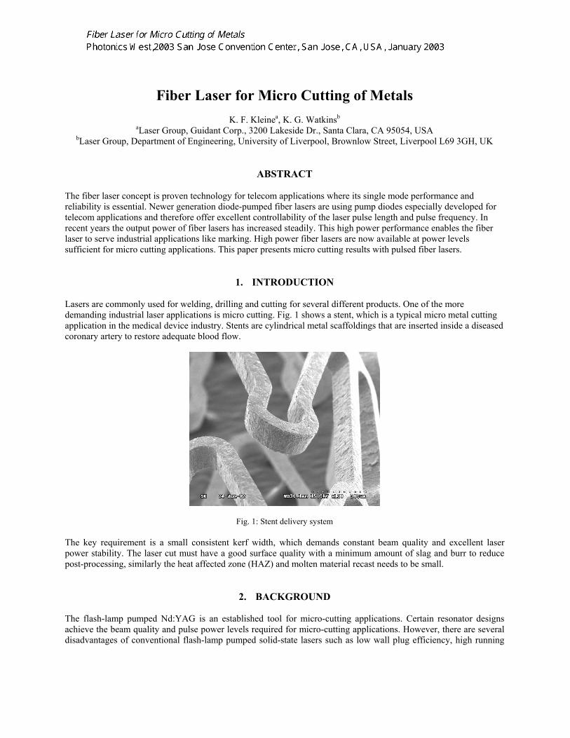
1. INTRODUCTION Lasers are commonly used for welding, drilling and cutting for several different products. One of the more demanding industrial laser applications is micro cutting. Fig. 1 shows a stent, which is a typical micro metal cutting application in the medical device industry. Stents are cylindrical metal scaffoldings that are inserted inside a diseased coronary artery to restore adequate blood flow.
Fig. 1: Stent delivery system
The key requirement is a small consistent kerf width, which demands constant beam quality and excellent laser power stability. The laser cut must have a good surface quality with a minimum amount of slag and burr to reduce post-processing, similarly the heat affected zone (HAZ) and molten material recast needs to be small.
2. BACKGROUND
The flash-lamp pumped Nd:YAG is an established tool for micro-cutting applications. Certain resonator designs achieve the beam quality and pulse power levels required for micro-cutting applications. However, there are several disadvantages of conventional flash-lamp pumped solid-state lasers such as low wall plug efficiency, high running
ERNIE
Text Box
Fiber Laser for Micro Cutting of Metals Photonics West,2003 San Jose Convention Center, San Jose, CA, USA, January 2003

costs and poor thermal stability [1]. Great improvements have been made in order to improve the thermal stability but most conventional lamp pumped laser systems on the production floor still require a high level of maintenance. Current investigations show that the single-mode fiber laser is an efficient, reliable and compact solution for micro machining. The diode-pumped technology offers low maintenance cycles and high conversion efficiency. Theoretical pump-light conversions of more than 80% are possible [2] but typical optical conversion efficiencies for Ytterbium (Yb) double-clad fiber lasers are 60-70% [3, 4]. Average power levels up to 100 W are possible with air-cooling. Since the overall efficiency is high, most fiber lasers are powered by a standard 110V supply. This investigation presents cutting results with a fiber laser. Furthermore it intends to show that pulsed fiber lasers provide cutting results comparable to regular pulsed lamp pumped Nd:YAG lasers. Laser peak pulse power for a given cutting speed and surface quality are investigated and compared to conventional Nd:YAG lasers. Previous experiments are leading to the proposal that the average power level is the major contributing factor to the recast layer thickness [10].
3. EXPERIMENTAL WORK 3.1. Laser Systems Used in the Experiments
The Fiber laser and Nd:YAG laser systems were set up with special care to accomplish a valid comparison independent from all cutting parameters beside the different laser sources.
3.1.1. Fiber Laser The cutting system used for the experiments integrates a CNC motion system, fiber laser, beam collimator and the cutting head. The cutting head includes a focusing optic and an assist gas nozzle. The nozzle exit hole diameter is 0.5 mm.
0
0.2
0.4
0.6
0.8
1
1.2
1.4
350 400 450 500 550 600
distance from focusing optic, z (mm)
beam
dia
mete
r (m
m)
Fig. 2: Beam propagation for fiber laser after collimator, M2 = 1.15
The fiber laser beam is created in the single mode core of the double clad fiber. The beam quality of the system was measured and is M2 = 1.15 (based on beam propagation measurements as shown in Fig 2). In the experiments presented here the laser was collimated to a 5 mm diameter, and then focused with a 50 mm focusing optic. The beam waist (df) in the focus can be obtained from [6]: M2 = df φ π ⁄ (2 λ) where, df = focus diameter φ = beam divergence λ = wavelength The theoretically calculated focus beam waist is 0.016 mm. The kerf width in the 0.100 mm to 0.150 mm steel samples was measured and is in the range of 0.018 to 0.020 mm.
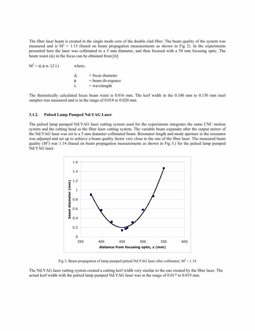
3.1.2. Pulsed Lamp Pumped Nd:YAG Laser The pulsed lamp pumped Nd:YAG laser cutting system used for the experiments integrates the same CNC motion system and the cutting head as the fiber laser cutting system. The variable beam expander after the output mirror of the Nd:YAG laser was set to a 5 mm diameter collimated beam. Resonator length and mode aperture in the resonator was adjusted and set up to achieve a beam quality factor very close to the one of the fiber laser. The measured beam quality (M2) was 1.14 (based on beam propagation measurements as shown in Fig 3.) for the pulsed lamp pumped Nd:YAG laser.
0
0.2
0.4
0.6
0.8
1
1.2
1.4
1.6
350 400 450 500 550 600
distance from focusing optic, z (mm)
beam
dia
mete
r (m
m)
Fig 3: Beam propagation of lamp pumped pulsed Nd:YAG laser after collimator, M2 = 1.14 The Nd:YAG laser cutting system created a cutting kerf width very similar to the one created by the fiber laser. The actual kerf width with the pulsed lamp pumped Nd:YAG laser was in the range of 0.017 to 0.019 mm.
3.2. Surface Roughness For the surface roughness measurement a VEECO 3300 N optical profiler with a measurement field size of 0.2 by 0.25 mm was used. The value recorded was Ra (average surface roughness). The sidewall was divided into three sections and the measurements were taken in the center of each section. The focus position and assist gas nozzle standoff were kept constant during the experiment. The standoff was 0.5 mm with a focus position optimized to achieve a minimum kerf width. Due to the fact that the fiber laser has no thermal lensing effect, the beam propagation does not change with variation of the pulse length, pulse power and frequency of the laser pulses. 99.99% pure oxygen was used as the assist gas for the experiments.
4. RESULTS AND DISCUSSION 4.1. Effect of Laser Peak Pulse Power on Surface Roughness
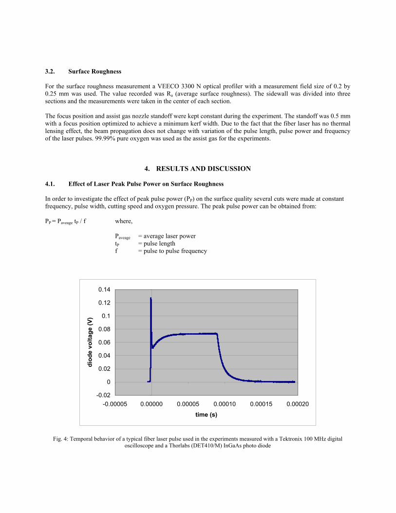
In order to investigate the effect of peak pulse power (PP) on the surface quality several cuts were made at constant frequency, pulse width, cutting speed and oxygen pressure. The peak pulse power can be obtained from: PP = Paveage tP / f where,
Paveage = average laser power tP = pulse length f = pulse to pulse frequency
-0.02
0
0.02
0.04
0.06
0.08
0.1
0.12
0.14
-0.00005 0.00000 0.00005 0.00010 0.00015 0.00020
time (s)
diod
e vo
ltage
(V)
Fig. 4: Temporal behavior of a typical fiber laser pulse used in the experiments measured with a Tektronix 100 MHz digital oscilloscope and a Thorlabs (DET410/M) InGaAs photo diode
Gating the pump diodes gates the fiber laser. The laser diode starts to pump the Yb-doped fiber 0.025 ms after the laser trigger signal; the laser output power then stabilizes at a stationary value after an initial spike caused by the diode power supply. The initial spike duration is <0.001 ms.
-0.02
0
0.02
0.04
0.06
0.08
0.1
0.12
0.14
-0.00005 0.00000 0.00005 0.00010 0.00015 0.00020
time (s)
diod
e vo
ltage
(V)
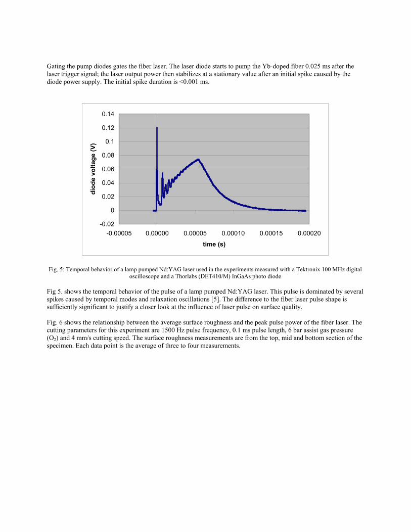
Fig. 5: Temporal behavior of a lamp pumped Nd:YAG laser used in the experiments measured with a Tektronix 100 MHz digital
oscilloscope and a Thorlabs (DET410/M) InGaAs photo diode Fig 5. shows the temporal behavior of the pulse of a lamp pumped Nd:YAG laser. This pulse is dominated by several spikes caused by temporal modes and relaxation oscillations [5]. The difference to the fiber laser pulse shape is sufficiently significant to justify a closer look at the influence of laser pulse on surface quality. Fig. 6 shows the relationship between the average surface roughness and the peak pulse power of the fiber laser. The cutting parameters for this experiment are 1500 Hz pulse frequency, 0.1 ms pulse length, 6 bar assist gas pressure (O2) and 4 mm/s cutting speed. The surface roughness measurements are from the top, mid and bottom section of the specimen. Each data point is the average of three to four measurements.

0.2
0.3
0.4
0.5
0.6
0.7
0.8
15 20 25 30 35 40 45
peak pulse power (W)
aver
age
roug
hnes
s, R
a ( µ
m)
topmidbottom
Frequency: 1500 Hz Pulse Length: 0.1 ms Gas Pressure: 6 bar (O2) Cutting speed: 4 mm/s 0,1 mm Stainless Steel
Fig. 6: Average surface roughness as a function of peak pulse power for a fiber laser cutting system
Zone I Zone II
Laser Beam
Fig. 7: optical profiler images at 20 W pulse power, Fig. 8: optical profiler images at 40 W pulse power,
fiber laser pulse power, fiber laser
The peak pulse power applied to create the cut shown in Fig. 7 was 20 W. It has a typical cut edge that appears to have two distinct zones. Zone I shows regular striations starting from the top edge of the laser cut. In zone II no or indistinct striations can be observed [7]. Fig. 8 shows the edge of a cut that was cut with a pulse power of 40 W. The higher peak pulse power increases the striations in zone I, only at the very bottom does the cut edge have no striations. At lower peak pulse power the surface quality degrades from the bottom to the top edge of the cut edge. In Zone II (also called the melt shear zone) the cut is dominated by the dynamics of the molten metal flow. At lower peak pulse power the surface roughness of the striations in zone I is lower than the surface roughness in zone II. Fig. 8 shows that the surface roughness is increasing with higher peak pulse power due to deeper natural striations along a wider area on the cut edge. The laser pulse frequency is significantly higher than the striation frequency observed in
zone I. This effect could be explained by the fact that the individual laser pulses at this frequency do not have sufficient energy to affect the striations and that the natural striation frequency is overriding the pulsing effect of the laser [8]. Section 4.3 will compare cutting results directly with the pulsed lamp pumped Nd:YAG laser.
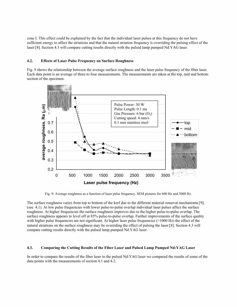
4.2. Effects of Laser Pulse Frequency on Surface Roughness
Fig. 9 shows the relationship between the average surface roughness and the laser pulse frequency of the fiber laser. Each data point is an average of three to four measurements. The measurements are taken at the top, mid and bottom section of the specimen.
0.2
0.3
0.4
0.5
0.6
0.7
0.8
0.9
1
0 500 1000 1500 2000 2500 3000 3500
Laser pulse frequency (Hz)
aver
age
roug
hnes
s, R
a ( µ
m)
topmidbottom
Pulse Power: 30 W Pulse Length: 0.1 ms Gas Pressure: 6 bar (O2) Cutting speed: 4 mm/s 0.1 mm stainless steel
Fig. 9: Average roughness as a function of laser pulse frequency. SEM pictures for 600 Hz and 3000 Hz.
The surface roughness varies from top to bottom of the kerf due to the different material removal mechanisms [9]. (see 4.1). At low pulse frequencies with lower pulse-to-pulse overlap individual laser pulses affect the surface roughness. At higher frequencies the surface roughness improves due to the higher pulse-to-pulse overlap. The surface roughness appears to level off at 85% pulse-to-pulse overlap. Further improvements of the surface quality with higher pulse frequencies are not significant. At higher laser pulse frequencies (>1000 Hz) the effect of the natural striations on the surface roughness may be overriding the effect of pulsing the laser [8]. Section 4.3 will compare cutting results directly with the pulsed lamp pumped Nd:YAG laser.
4.3. Comparing the Cutting Results of the Fiber Laser and Pulsed Lamp Pumped Nd:YAG Laser
In order to compare the results of the fiber laser to the pulsed Nd:YAG laser we compared the results of some of the data points with the measurements of section 4.1 and 4.2.

Typical cutting parameters for the Nd:YAG laser for micro machining are 1500 Hz pulse-to-pulse frequency, 0.1 ms pulse length, 6 bar oxygen pressure, 30 W laser peak power and 4 mm/s cutting speed. The following two figures are optical profiler images of side walls with the fiber laser cutting system and the pulsed lamp pumped Nd:YAG laser at those laser settings.
Fig 10: Optical profiler picture of laser cut side Fig 11: Optical profiler picture of laser cut with the fiber laser side wall with pulse lamp pumped Nd:YAG laser In Figure 10, a 30 W peak pulse power Nd:YAG laser system created a maximal Ra of 0.61 µm compared to 0.48 µm with the fiber laser (Fig. 11).
Top
Fig 12: SEM picture of laser cut side Fig 13: SEM picture of laser cut wall with the fiber laser side wall with pulse lamp pumped Nd:YAG laser Figures 12 and 13 are SEM pictures of the side walls of cuts with the fiber laser and the pulsed Nd:YAG laser system at 2000 Hz pulse-to-pulse frequency, 0.1 ms pulse length, 6 bar oxygen pressure, 35 W laser peak power and 4 mm/s cutting speed for 0.15 mm stainless steel. Zone I (see Fig. 7) is larger with the pulsed lamp pumped Nd:YAG laser but measurements with the optical profiler show equivalent surface quality (∆ Ra < 0.2 µm) for both laser systems.
5. CONCLUSIONS
• The fiber laser, due to its good beam quality, is able to achieve very small focus diameters and small kerf widths and is an excellent tool for micro-cutting.
• The cuts produced by the fiber laser show very similar features to those produced with a lamp pumped pulsed Nd:YAG laser.
• The surface quality of a cut in stainless steel can be improved by optimizing the cutting parameters of the fiber laser and are comparable with standard lamp pumped Nd:YAG lasers.
• Lowering peak pulse power results in less pronounced striations and hence improved surface roughness. The peak power requirements for lamp pumped Nd:YAG lasers and fiber lasers are comparable although the temporal development is different.
• Like experiments reported with lamp pumped pulsed Nd:YAG lasers, there is no significant improvement of surface roughness with the fiber laser system beyond 85% pulse-to-pulse overlap.
REFERENCES 1 H.K. Toenshoff, A. Ostendorf, K. Schaefer, Fiber Laser – Compact Source for Micro Welding, ICALEO, 1998 2 V. Reichel, S. Unger, V. Hagemann, H. Muller, M. Auerbach, 8 W highly efficient Yb-doped fiber laser,
Proceedings of SPIE Vol. 3889, 2000 3 J. Nilsson, A.B. Grudinin, P.W. Turner, Advanced pulsed and CW high-power fiber laser, CLEO Proceedings,
2000 4 A. Schoenfelder, Fiber lasers address micromachining methods, Laser Focus World, June 1999 5 W. Koechner, Solid-State Laser Engineering, Fourth Edition, Springer, 1996 6 E. Beyer, O. Marten, K. Behler, J.M. Weick, Laser cutting, Laser and Optoelektronik, Sept. 1985 7 C.S. Lee, A. Goel, H. Osada, Parametric studies of pulsed-laser cutting of thin metal plates, Amada
Engineering, Jan. 1985 8 V. King, J. Powell, Laser-cut mild steel - factors affecting edge quality, E.I. Monthly, April 1985 9 P.M. Ilavarasan, P.A. Molian, Modeling of Surface Roughness in Laser Cutting, Proceedings of fifth Int. FAIM
Conference, Stuttgart, Germany, June 1995 10 K.F. Kleine, K.G. Watkins, B. Whitney, Use of Fiber Laser for Cutting Applications in the Medical Device
Industry, ICALEO, Scottsdale, October 2002